

Data Sheet
Motor operated valve, type ICMTS
with actuator, type ICAD 600A-TS
The ICMTS is a direct operated motorised valve
driven by actuator type ICAD 600A-TS. The
ICMTS is designed to regulate the ow of
transcritical gas or subcritical liquid from the
gascooler in transcritical CO2 systems. The
ICMTS can also be used for other control
functions in CO2 systems. The ICMTS valve is
designed so that the opening and closing
forces are balanced.
ICAD 600A-TS actuators can be controlled using
the following signals:
• 0 – 20 mA
• 4 – 20 mA (default)
• 0 – 10 V
• 2 – 10 V
ICAD 600A-TS actuators can also operate an
ICMTS valve as an On/O function supported
by a digital input.
The ICMTS valve can be operated manually via
the ICAD 600A-TS actuator or via the Multifunction tool for ICMTS (see the Ordering).
The actuator type 600A-TS is designed
specically for ICMTS valves. The actuator type
900 can be used for ICMTS as well, however it
consumes more energy than ICAD 600A-TS for
similar applications.
The ICAD 600A-TS is controlled via a
modulating analogue signal (e.g. 4 – 20 mA / 2
– 10 V) or a digital ON/OFF signal. ICAD 600A-TS
incorporates an advanced MMI (Man Machine
Interface), including continuous display of
Opening Degree, which gives the user a very
advanced and exible setup procedure that can
meet many dierent applications. The ICMTS
valve is typically controlled by the Danfoss EKC
326A controller.
AI217586428573en-001101

Motor operated valve, type ICMTS with actuator, type ICAD 600A-TS
Features
Valves
• Designed for high pressure CO2 systems with applications for a maximum working pressure of 140 bar / 2030 psig.
• Applicable to R744 (CO2)
• Direct coupled connections
• Connection types are DIN butt weld
• Non-alloyed quality steel
• Low weight and compact design
• Regulating cone ensures optimum regulating accuracy, particularly at part load
• Manual opening possible via ICAD 600A-TS or Multi-function tool
• The PTFE seat provides excellent valve tightness
• Magnet coupling - real hermetic sealing
• ICAD 600A-TS include encoder function that will provide a true valve position feedback to Danfoss controller or
non-Danfoss control systems.
Actuator
• Specically designed for ICMTS valve
• Advanced and high speed Digital Stepper Motor Technology
• Seven segment LCD display including three programming keys
• Valve opening degree can be observed continuously
• Can easily be congured to dierent applications on-site. (change speed, ON/OFF, modulating valve)
• Open – Close time: 3 seconds
• Modulating or ON/OFF operation
• Multiple speed selection during operation
• Logging of old alarms
• Password protection
• Control input signal: 4 – 20 mA, 0 – 20 mA, 0 – 10 V, 2 – 10 V
• Position feed back: 0 – 20 mA, 4 – 20 mA (ICMTS)
• 3 digital ON/OFF feedback
• Resolution: 20 micron/step (0.02 mm stroke pr. step)
• Total steps: 250
• Auto Calibration, Neutral zone
• In the event of a power failure, multiple fail safe options are possible. During power failure, ICAD 600A-TS can be
selected to:
Close ICMTS
Open ICMTS
Stay in the position it was in, prior to power failure. Go to a specic ICMTS valve opening degree.
• Hermetic magnetic motor
• Enclosure: IP 67 (~NEMA 6)
• Approvals: CE, UL, CRN
• Connectors for easy installation and servicing
• Can be controlled by Danfoss EKC 326A controller and integrated into Danfoss ADAP-KOOL® system.
© Danfoss | Climate Solutions | 2021.11 AI217586428573en-001101 | 2
P
1
a
b
c
g
d
f
e
Danfoss
27H227
Motor operated valve, type ICMTS with actuator, type ICAD 600A-TS
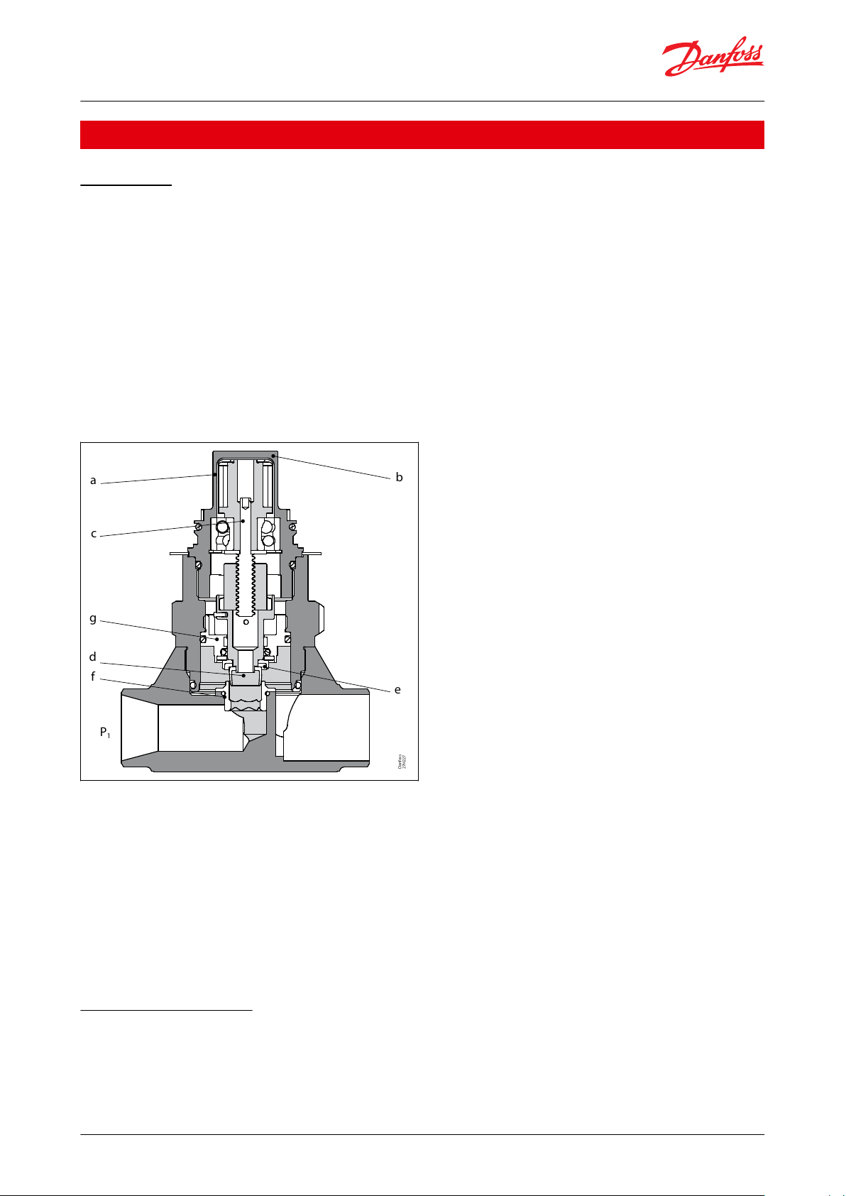
Function
ICMTS valve
The ICMTS motor valve is designed for use with ICAD 600A-TS.
The driving force from the actuator is transferred via a magnetic coupling (a) through the stainless steel top housing
(b), thus eliminating the need for a packing gland. The rotational movement of the magnetic coupling (a) is
transferred to a spindle (c) which in turn provides the vertical movement of the cone (d) and PTFE valve plate (e), to
open and close the valve. The closing force of the actuator combined with the PTFE valve plate (e) and valve seat (f)
provides an eective seal to prevent leakage across the valve port, when the valve is in the closed position. To
prevent damage to the PTFE valve plate (e) and seat (f) from system debris, it is recommended to install a lter in
the system.
Valve inlet pressure (P1) acting on the underside of the PTFE valve plate (e) also passes through the hollow cone
assembly (d) on to the top of the piston (g) and balances the pressure acting on the piston (g). Any trapped liquid
across the throttle cone (d) is equalised down to the valve outlet without aecting the valve performance.
Figure 1: ICMTS
The actuators have a fully weather protected enclosure with none of the moving parts exposed to the environment.
The fast acting actuators and balanced valve design results in the valve being able to move from the fully closed to
the fully open position in about 3 seconds.
The smallest cones (A33 and A) are log-shaped in order to provide optimum regulation at small capacities and high
pressure dierentials.
The rst version of the ICMTS valve features V-shaped A cones. Please contact your local Danfoss sales
company for further info.
Bigger cones (B and C) are V-shaped in order to provide an optimum regulating curve for higher capacities.
ICAD 600A-TS actuator
The design of ICAD 600A-TS is based on a digital stepper motor technology combined with an advanced MMI (Man
Machine Interface), that gives excellent possibilities for having a high degree of exibility with the same type of
ICAD 600A-TS actuator.
The Opening Degree (0-100 %) of the actual ICMTS valve installed can be continuously observed on the ICAD 600ATS display.
© Danfoss | Climate Solutions | 2021.11 AI217586428573en-001101 | 3

Motor operated valve, type ICMTS with actuator, type ICAD 600A-TS
The advanced menu system will allow several parameters to be adjusted to obtain the required function.
Many dierent parameters can be congurated, among these:
• Modulating and ON/OFF control
• Analogue input
0 – 20 mA or 4 – 20 mA
0 – 10 V or 2 – 10 V
• Analogue output
0 – 20 mA or 4 – 20 mA
• Automatic or manual control
• Change of ICMTS valve speed
• Automatic calibration
• Multiple Fail Safe set-up options during power cut
For service all Input and Output signals can be recalled and observed from the ICAD 600A-TS display.
A password protection has been linked to the parameter of entering the correct ICMTS valve to avoid unintentional
and non-authorised operation.
The design of ICAD 600A-TS is based on a digital stepper motor technology combined with an advanced MMI (Man
Machine Interface), that gives excellent possibilities for having a high degree of exibility with the same type of
ICAD 600A-TS actuator.
The Opening Degree (0-100 %) of the actual ICMTS valve installed can be continuously observed on the ICAD 600ATS display.
The advanced menu system will allow several parameters to be adjusted to obtain the required function.
Many dierent parameters can be congurated, among these:
• Modulating and ON/OFF control
• Analogue input
0 – 20 mA or 4 – 20 mA
0 – 10 V or 2 – 10 V
• Analogue output
0 – 20 mA or 4 – 20 mA
• Automatic or manual control
• Change of ICMTS valve speed
• Automatic calibration
• Multiple Fail Safe set-up options during power cut
© Danfoss | Climate Solutions | 2021.11 AI217586428573en-001101 | 4
EKC 326A
AKS 11
AKS 2050
ICMTS
AKS
2050
Gas cooler
From evaporator
To evaporator
CCM
Motor operated valve, type ICMTS with actuator, type ICAD 600A-TS
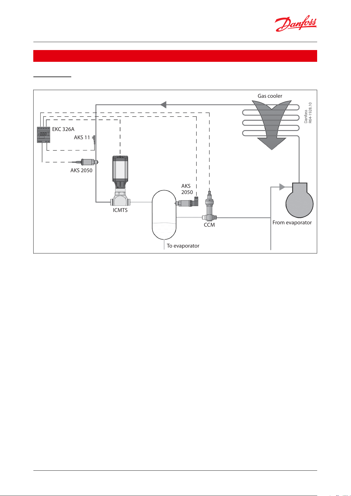
Application
ICMTS valve
Figure 2: Application
The ICMTS valve is developed for transcritical CO2 applications. The ICMTS valve can be used in systems with ash
gas bypass, parallel compression as well as in stand-alone application. The ICMTS valve can be used in transcritical
and subcritical conditions.
The most typical application is with ash gas bypass.
Pressure optimisation is performed by the Danfoss EKC 326A controller and the ICMTS valve which is installed at the
outlet of the gas cooler (see Figure 2: Application). This design provides the possibility to optimise gas cooler
pressure and intermediate receiver pressure independently.
The pressure in the receiver is one important parameter, but the design of the receiver is also important. It typically
acts as a liquid separator as well.
In order to keep the intermediate pressure low, ash gas is expelled through a gas bypass valve to the suction side
of the compressor. The two phase mixture from the ICMTS valve has to be separated before gas enters the gas
bypass.
Please refer to the Danfoss Application guide, DKRCE.PA.R1.A for more information on CO2 systems.
© Danfoss | Climate Solutions | 2021.11 AI217586428573en-001101 | 5

Motor operated valve, type ICMTS with actuator, type ICAD 600A-TS
Media
Refrigerants
Applicable to R744 (CO2). ICMTS valves must not be used with ammable refrigerants. For further information,
please contact your local Danfoss sales company.
New refrigerants
Danfoss products are continually evaluated for use with new refrigerants depending on market requirements.
When a refrigerant is approved for use by Danfoss, it is added to the relevant portfolio, and the R number of the
refrigerant (e.g. R513A) will be added to the technical data of the code number. Therefore, products for specic
refrigerants are best checked at store.danfoss.com/en/, or by contacting your local Danfoss representative.
© Danfoss | Climate Solutions | 2021.11 AI217586428573en-001101 | 6

Features
Specications
Connections
ICMTS valves are available with DIN butt weld connections.
Design
Valve body and top cover material
Temperature range
Media: –60/+120 °C (–76/+248 °F)
Pressure
Max. working pressure: 140 bar g (2030 psig)
Surface protection
The external surface is treated in order to provide good corrosion protection
Max. opening pressure dierential (MOPD)ICMTS: 90 bar (1305 psi)
The time it takes to move from Closed to Open position or in reverse order with maximum selected speed at ICAD 600A-TS
is 3 seconds.
Features
Specications
Materials
Housing: Aluminium
Top part of ICAD 600A-TS: PBT thermo plastic
Weight
ICAD 600A-TS: 1.2 kg (2.64 lb)
Temperature range (ambient)
–30 °C / +50 °C (–22 °F / 122 °F)
Enclosure
IP 67 (~NEMA 6)
Cable connection
Can be ordered with or without cables included.
If ordered with cables:
2 cables in length of 1.5 m length (60 in.) with M12 connectors included
Supply cable
3 × 0.34 mm2 (3 × ~22 AWG)
Ø4.8 mm (diameter 0.19”)
Control cable
7 × 0.25 mm2 (7 × ~24 AWG)
Ø6 mm (diameter 0.24”)
Features
Specications
Electrical data
Supply voltage is galvanic isolated from Input/Output
Supply voltage
Load: 24 V DC, + 10% / -15%
ICAD 600A-TS: 1.2 A
Fail safe supply
Min. 19 V DC, max. 26.4 V DC
Load: ICAD 600A-TS: 1.2 A
Battery capacity
For each open/closed cycle
ICAD 600A-TS:
Speed Parameter i04=100 (max. speed): 2 mAh
Speed Parameter i04=1 (min. speed): 200 mAh
Analogue input
Current: 0/4 – 20 mA
Load: 200 Ω
Voltage: 0/2 – 10 V DC
Load: 10 kΩ
Analogue output
Current: 0/4-20 mA
Load: ≤ 250 Ω
Digital input
Digital ON/OFF input by means of volt-free contact (Signal/Telecom relays with gold-plated contacts recommended) –
Voltage input used
• ON: contact impedance < 50 Ω)
• OFF: contact impedance > 100 kΩ
Digital output
3 pcs. NPN transistor output
External supply: 5 – 24 V DC
(Same supply as for ICAD 600A- TS can be used, but please note that the galvanically isolated system will then be spoiled).
Output load: 50 Ω
Load: Max. 50 mA
Motor operated valve, type ICMTS with actuator, type ICAD 600A-TS
Product specication
Technical data
ICMTS valve
Table 1: Technical data - Valve
ICAD 600A-TS actuator
Table 2: Technical data - Actuator
Table 3: Electrical connections
Cable connection
Cable connection - Two 1.5 m (60 in) cables premounted
© Danfoss | Climate Solutions | 2021.11 AI217586428573en-001101 | 7

Terminal box -
not supplied
by Danfoss
Danfoss
M27H0097
12Control cable
Supply cable
III
I
II
C
D
E
B
A
G
F
Danfoss
M27H0137
Ref.
Colour
Charge
Description
8 pin male connector
A
Black
–
Common AlarmBBrown
–
ICMTS fully openCRed
–
ICMTS fully closed
D
Orange
–
GND groundEYellow
+
0/4 - 20 mA Input
F
Green
+
0/2 - 10 V InputGBlue
+
0/4 - 20 mA Output
4 pin male connector
I
Black
+
Fail safe supply Battery / UPS
(1)
19 V DC
II
White
+
Supply voltage 24 V DC
III
Brown
–
Motor operated valve, type ICMTS with actuator, type ICAD 600A-TS
Figure 3: Cable connection
Figure 4: Rear view
Table 4: Connection
(1)
(1)
Uninterruptable Power Supply
Uninterruptable Power Supply
NOTE:
Colour code changed when compared to older colour wiring diagram.
© Danfoss | Climate Solutions | 2021.11 AI217586428573en-001101 | 8

Motor operated valve, type ICMTS with actuator, type ICAD 600A-TS
Fail Safe supply options
Figure 5: ICAD
600A-TS
In the event of a power failure, multiple fail safe options are possible, provided that a ICAD-UPS or similar is used.
During power failure, ICAD 600A-TS can be selected to:
• Close ICMTS
• Open ICMTS
• Stay in the position it was in, prior to power failure
• Go to a specic ICMTS valve opening degree
See the ICAD-UPS for ICMTS for further information.
NOTE:
A fail safe supply (battery or UPS) is required.
ICAD-UPS for ICMTS
Figure 6: ICAD-UPS
ICAD-UPS is designed for using with ICMTS valve.
In the event of power failure, there is a need to make sure that the ICMTS goes to a safe position. ICAD-UPS can be
connected to the ICAD 600A-TS.
The solution of connecting ICMTS with ICAD 600A-TS to ICAD-UPS will give one of the following possibilities in the
event of power failure:
© Danfoss | Climate Solutions | 2021.11 AI217586428573en-001101 | 9

ICAD-UPS
Input Output
+ - + -+ - + -
+
-
+
-
ICAD-UPS
Input
Output
24 V DC
0.5 A
24 V DC
Black (+)
White (+)
Brown (–)
Black (+)
White (+)
Brown (–)
max. 8 pcs. of ICAD 600A-TS
Danfoss
27H216
Motor operated valve, type ICMTS with actuator, type ICAD 600A-TS
• close ICMTS
• open ICMTS
• stay
• go to a specic ICMTS Opening Degree
When power supply has been re-established the system will automatically return to normal operation.
Facts and features
• Industrial product
• Can support up to 8 pcs. of ICAD 600A-TS
• Integrated solution - battery and UPS
• Industrial approvals:
CE, UL, GL (Germanisher Lloyd)
• DIN rail mounting
◦ LED indication
◦ Green (Power ON)
◦ Yellow (Flashing: charging, Constant: Buer mode (Failsafe supply to ICAD 600A- TS))
◦ Red (Battery fully discharged/Battery faulty)
• 24 V DC supply → Same transformer as for ICAD 600A-TS can be used. Only +0.5 A extra load on the transformer.
• Check of battery every 60 sec.
•
Adjustable buer time
• Forced remote shutdown in buer mode via digital input
• 3 digital volt free relay change over contacts for signals to PLC systems. (Power OK, Buer mode (failsafe supply to
ICAD 600A-TS), Alarm).
(1)
. (1, 2, 3, 5, 10, 15, 20, 30 or innity) = Ensures longer battery life time.
Code number: 027H0182
For further information, please see the instruction AN000086416706.
Applications
Figure 7: Seperate 24 V DC tranformer for both ICAD-UPS and ICAD 600A-TS
1
Buer time is dened as the period whereICAD 600A-TS is only powered from the ICAD-UPS (i.e. not from main supply). On ICAD-UPS there is an
adjustable buer time setting (1, 2, 3, 5, 10, 15, 20, 30 min. or innity). If set to 3, ICAD-UPS will switch o power to connected ICAD 600A-TS, 3
minutes after the power failure occurs. This ensures that the internal battery inside ICAD-UPS does not fully discharge.
© Danfoss | Climate Solutions | 2021.11 AI217586428573en-001101 | 10

ICAD-UPS
Input Output
+ - + -+ - + -
+
-
ICAD-UPS
Input
Output
24 V DC
Black (+)
White (+)
Brown (–)
Black (+)
White (+)
Brown (–)
max. 8 pcs. of ICAD 600A-TS
Danfoss
27H217
4
2c
2
3
6
5
1
Danfoss
27H226
Motor operated valve, type ICMTS with actuator, type ICAD 600A-TS
Figure 8: One 24 V DC tranformer for ICAD-UPS and ICAD 600A-TS
Material specication
Figure 9: Material specication
© Danfoss | Climate Solutions | 2021.11 AI217586428573en-001101 | 11

No.
Part
Material
EN
ASTM
1
Housing
Low temperature steel
S235J2, EN10025
A5152Top cover / function module
Low temperature steel
S355J2, EN10025
LCC, A352
2c
O-ring
Chloroprene (Neoprene)
3
O-ring
Chloroprene (Neoprene)
4
Actuator
5
O-ring
Chloroprene (Neoprene)
6
Seat
Stainless steel
+15/+5 °C
[kW]
+30/+5 °C
[kW]
+38 (100 bar)/ +5 °C
[kW]
ICMTS 20-A33
16.7
16.1
25
ICMTS 20-A
504875
ICMTS 20-B
291
278
423
ICMTS 20-C
479
454
675
+15/+5 °C
[kW]
+30/+5 °C
[kW]
+38 (100 bar)/ +5 °C
[kW]
ICMTS 20-A33
18.52325
ICMTS 20-A
566975
ICMTS 20-B
325
400
423
ICMTS 20-C
540
655
675
+15/+5 °C
[kW]
+30/+5 °C
[kW]
+38 (100 bar)/ +5 °C
[kW]
ICMTS 20-A33
20.4
26.5
25
ICMTS 20-A
618075
ICMTS 20-B
355
470
423
ICMTS 20-C
585
760
675
Motor operated valve, type ICMTS with actuator, type ICAD 600A-TS
Table 5: Material specication
ICMTS capacities
It is relatively complex to correctly size a valve for transcritical applications, especially as the mass ow of the
refrigerant changes, drastically moving from transcritical to subcritical conditions. At the same time, temperature
variations in the intermediate vessel downstream of the valve, will not signicantly aect the sizing the valve.
It is recommended to calculate the ICMTS valve using Danfoss DIRcalcTM software following these steps:
• Calculate the ICMTS valve as an expansion valve in the liquid line with the following conditions: Tcond = +30 °C,
Tevap = temperature in the intermediate vessel, 0 K subcooling.
• Check the selected valve for the winter conditions: e.g. Tcond = +15 °C with 5 K subcooling
• Possible part load of the system at Tcond = +30 °C, Tevap = temperature in the intermediate vessel, 10 K
subcooling. (night operation or the smallest capacity step of the power pack). The part load of the valve should be
above 10%.
Quick capacity selection could be done using the following table:
Table 6: 0 K subcooling in the subcritical mode
Table 7: 5 K subcooling in the subcritical mode
Table 8: 10 K subcooling in the subcritical mode
Please contact your local Danfoss sales oce if you need assistance in your selection of ICMTS valves.
© Danfoss | Climate Solutions | 2021.11 AI217586428573en-001101 | 12

L3
L4
H
2
H
1
L
H
L1
L2
Danfoss
27H225
Connection
H
H1H
2
L
(1)
L1L2L3L
4
Weight ICMTS incl.
ICAD 600A-TS
25 D (1 in.)
mm401959465866860107
3.3 kg
in.
1.58
7.68
3.7
2.56
3.39
2.68
2.36
4.21
6 lb.
SizemmSize
in.ODmmTmmODin.Tin.
25-133.7
2.6
1.327
0.103
Motor operated valve, type ICMTS with actuator, type ICAD 600A-TS
Dimensions
Figure 10: Dimensions
Table 9: Dimension
(1)
(1)
Include space for ICAD Protection cap.
Include space for ICAD Protection cap.
NOTE:
Weight is approximated only.
Connections
Figure 11: Butt weld DIN (EN 10220)
Table 10: Butt weld DIN (EN 10220)
General operation
ICAD 600A-TS is equipped with an MMI (Man Machine Interface) from which it is possible to monitor and change the
setting of parameters to adapt the ICAD 600A-TS and the corresponding ICMTS to the actual refrigeration
application.
© Danfoss | Climate Solutions | 2021.11 AI217586428573en-001101 | 13

Danfoss
27H73
1234“Down” arrow push button
Enter
“Up” arrow push button
Display
"Down"arrow Enter "Up" arrow
Motor operated valve, type ICMTS with actuator, type ICAD 600A-TS
Figure 12: Display
The setting of parameters is managed by means of the integrated ICAD 600A-TS MMI (see Figure 12 and Figure 13)
and consists of:
• “Down” arrow push button (Figure 12, pos. 1)
◦ Decreases parameter number by 1 at each activation.
• “Up” arrow pushbutton (Figure 12, pos. 3)
◦ Increases parameter number by 1 at each activation.
• Enter push button (Figure 12, pos. 2)
◦ Gives access to the Parameter list by keeping the push button activated for 2 seconds. A Parameter list example
is shown below (parameter ¡08, see Figure 14).
◦ Gives access to change a value once the Parameter list has been accessed
◦ Acknowledge and save change of value of a parameter.
◦ To exit from the Parameter list and return to the display of Opening Degree (OD), keep the Enter button
activated for 2 seconds.
• Display (Figure 12, pos. 4)
◦ The Opening Degree (OD) 0 - 100 % of the ICMTS valve is normally displayed. When the push buttons are not
activated for 20 seconds, the display will return to OD (see Figure 15).
• Displays the parameter
• Displays the actual value of a parameter
• Displays the function status by means of text (Figure 12, pos. 4)
◦ Mod represents that ICAD 600A-TS is positioning the ICMTS valve according to an analogue input signal
(Current or Voltage).
◦ Low represents that ICAD 600A-TSS is operating the ICMTS valve like an ON/OFF solenoid valve with low speed
according to a digital input signal.
◦ Med represents that ICAD 600A-TS is operating the ICMTS valve like an ON/OFF solenoid valve with medium
speed according to a digital input signal.
◦ High represents that ICAD 600A-TS is operating the ICMTS valve like an ON/OFF solenoid valve with high speed
according to a digital input signal (see Figure 16).
Figure 13: Display
Figure 14: Parameter Figure 15: Display - OD
© Danfoss | Climate Solutions | 2021.11 AI217586428573en-001101 | 14

Description
ICAD alarm text
Denition of event
Comments
No Valve type selected
A1
Alarm ON
At start-up A1 will be displayed
Controller fault
A2
Alarm ON
Internal fault inside electronics.
Carry out:
1. Power OFF and Power ON
If A2 still active.
2. Make a Reset to factory setting
If A2 still active. Return ICAD to Danfoss
AI input errorA3Alarm ON
Not active if ¡01 = 2, or ¡02 = 2
When ¡03 = 1 and AI A > 22 mA
When ¡03 = 2 and AI A > 22 mA or AI A < 2 mA
When ¡03 = 3 and AI A > 12 V
When ¡03 = 4 and AI A > 12 V or AI A < 1 V
Low voltage of fail safe Supply
A4
Alarm ON
If 5 V < fail safe supply <18 V. Enabled by ¡08
Check supply to ICAD
A5
Alarm ON
If supply voltage < 18 V
Calibration extended failed
A6
Alarm ON
Check valve type selected. Check presence of foreign body internally in
ICMTS valve
Internal temperature alarm
A7
Alarm ON
Temperature for stepper motor component too high.Ventilate/lower ambient ICAD temperature
A8
Alarm ON
Temperature for stepper motor component too high. Ventilate/lower ambient ICAD temperature.
Valve lockedA9Alarm ON
Only active if i16 = 1 If the valve is locked in more than 15 seconds. ICMTS
stopped and hold position A9 ashing in display A9 alarm can only be reset
by Power OFF/ON of ICAD
Motor operated valve, type ICMTS with actuator, type ICAD 600A-TS
Figure 16: Display - High
Alarms
Table 11: Alarms
If an alarm has been detected, the ICAD 600A-TS display (see
Figure 12: Display) will alternate between showing
Actual alarm and Present Opening Degree.
If more than one alarm is active at the same time, the alarm with the highest priority will take preference. A1 has the
highest priority, A5 the lowest.
Any active alarm will activate the Common Digital Alarm Output (Normally Open).
All alarms will automatically reset themselves when they physically disappear.
Old alarms (alarms that have been active, but have physically disappeared again) can be found in parameter ¡11.
Parameter list
Valid from: (i58:11, i59:36) and onwards
NOTE:
The rst parameter to be entered shall be: ¡26
© Danfoss | Climate Solutions | 2021.11 AI217586428573en-001101 | 15

Description
ICAD
parameter
Min
Max
Factory
Setting
Stored
Unit
Password
Comments
OD (Opening
degree)
-
0
100%-
ICMTS valve Opening Degree is displayed during normal operation.
Running display value (see ¡01, ¡05).
Main Switch
¡01
121√-NoInternal main switch
1. Normal operation
2. Manual operation. Valve Opening Degree will be ashing. With
the down arrow and the up arrow push buttons the OD can be entered manually.
Mode
¡02
121√-NoOperation mode
1. Modulating – ICMTS positioning according to Analog Input (see
¡03)
2. ON/OFF - operating the ICMTS valve like an ON/OFF solenoid
valve controlled via Digital Input. See also ¡09.
3. Neutralzone / 3 point control. Increase/Decrease Opening Degree
by Digital Input.
AI signal
¡03
142√-NoType of AI signal from external controller
1. 0 – 20 mA
2. 4 – 20 mA
3. 0 – 0 V
4. 2 – 10 V
Speed
In Modulating
Mode
Opening/closing speed
In ON/OFF
Mode
Opening speed
¡04
1
100
50/ 100√-NoSpeed can be decreased. Max. speed is 100 % - Not active in manual
operation (¡01 = 2)
If ¡26 = 1 - 3 then factory setting =100
If ¡26 = 4 - 9 then factory setting = 50
If ICMTS is opening and (¡04 < = 33) or ICMTS is closing and (¡14 < =
33) => Low is displayed.
If ICMTS is opening and (33 < If ¡04 < = 66) or ICMTS is closing and
(33 < If ¡14 < = 66) => Med is displayed.
If ICMTS is opening and (¡04 > = 67) or ICMTS is closing and (¡14 > =
67) => High is displayed"
Automatic calibration
¡05
020-No
Not active before ¡26 has been operated. Always auto reset to 0. CA
will ash in the display during calibration, if Enter push button has
been activated for two seconds
0: No Calibration
1: Normal forced calibration - CA ashing slowly
2: Extended calibration – CA ashing rapidly
AO signal
¡06
022√-NoType of A0 signal for ICV valve position
0: No signal
1: 0-20 mA
2: 4-20 mA
Failsafe
¡07
141√-NoDene condition at power cut and fail safe supply is installed.
1: Close valve
2: Open Valve
3: Maintain valve position
4: Go to OD given by ¡12
Fail safe supply
¡08
010√Yes
Fail safe supply connected and enable of A4 alarm
0: No
1: Yes
DI function
¡09
121√No
Dene function when DI is ON (short circuited DI terminals) when
¡02 = 2
1: Open ICMTS valve (DI = OFF = > Close ICMTS valve)
2: Close ICMTS valve (DI = OFF = > Open ICMTS valve)
Password
¡10
0
1990-
-
Enter number to access password protected parameters: ¡26 Password = 11
Old Alarms
¡11
A1
A99--NoOld alarms will be listed with the latest shown rst. Alarm list can be
reset by means of activating down arrow and up arrow at the same
time for 2 seconds.
OD at power
cut.
¡12
0
10050√
No
Only active if ¡07 = 4
If fail safe supply is connected and power cut occurs, the ICMTS will
go to the specied OD.
Inverse operation
¡13
010√No
When ¡02 = 1
0: Increasing Analog Input signal => Increasing ICMTS Opening Degree
1: Increasing Analog Input signal => Decreasing ICMTS Opening Degree
When ¡02 = 3
0: DI1 = ON, DI2 = OFF => Increasing ICMTS Opening Degree.
DI1 = OFF, DI2 = ON => Decreasing ICMTS Opening Degree
DI1 = DI2 = OFF => ICAD/ICMTS maintain current position
DI1 = DI2 = ON => ICAD/ICMTS maintain current position
1: DI1 = ON, DI2 = OFF => Decreasing ICMTS Opening Degree
DI1 = OFF, DI2 = ON => Increasing ICMTS Opening Degree
DI1 = DI2 = OFF => ICAD/ICMTS maintain current position
DI1 = DI2 = ON => ICAD/ICMTS maintain current position
Motor operated valve, type ICMTS with actuator, type ICAD 600A-TS
Table 12: Parameter list
© Danfoss | Climate Solutions | 2021.11 AI217586428573en-001101 | 16

Description
ICAD
parameter
Min
Max
Factory
Setting
Stored
Unit
Password
Comments
In ON/OFF
Mode Closing
speed
¡14
0
100
50/ 100√-
No
See ¡04.
If ¡26= 1 - 3 then factory settin qg = 100
If ¡26= 4 - 9 then factory setting = 50
Manual set
point
¡15
0
1000No
When ¡01= 2, ¡15 determine the start up value.
Encoder operation
¡16
010/1√Yes
NB: Password protected. Password = 7
If ¡26 = 1 - 3 then factory setting = 0
If ¡26 = 4 - 6 then factory setting = 0
If ¡26 = 7 - 9 then factory setting = 1
0: Encoder disabled. Means ICAD operation as ICAD 600A-TS
1: Encoder enabled
Forced closing
when ICMTS
valve Opening
Degree < 3%
i17
010√-NoEnable/Disable forced closing
0: When ICMTS valve Opening Degree < 3% it will be forced to close
regardless of requested ICMTS valve Opening Degree
1: When ICMTS valve Opening Degree < 3% no forced to closing will
take place
ICMTS congu-
ration
¡26
090√Yes
NB: Password protected. Password = 11
0: No valve selected. Alarm A1 will become active.
1: ICMTS 20 with ICAD 600A-TS
Description
ICAD
parameter
Min
Max
Factory
Setting
Stored
Unit
Password
Comments
OD %
¡50
0
100-%-ICMTS valve Opening Degree
AI [mA]
¡51
0
100-mA-AI signal
AI [V]
¡52
0
100-V-AI signal
AO [mA]
¡53
0
100-mA-A0 signal
DI
¡54
01---
DI signals. Depending of ¡02
If ¡02 = 2, one digits are shown.
0: DI1 = OFF
1: DI1 = ON
If ¡02 = 3, two digits are shown.
00: DI1 = OFF, DI2 = OFF
10: DI1 = ON, DI2 = OFF
01: DI1 = OFF, DI2 = ON
11: DI1 = ON, DI2 = ON
DO Close
¡55
01---
DO Closed status. ON when OD < 3 %
DO Open
¡56
01---
DO Open status. ON when OD > 97 %
DO Alarm
¡57
01---
DO alarm status. ON when a Alarm is detected
Display mP SW
ver.
¡58
0
100---Software version for display microprocessor
Motor mP SW
ver.
¡59
0
100---Software version for motor microprocessor
Motor operated valve, type ICMTS with actuator, type ICAD 600A-TS
Table 13: Service
Reset to factory setting:
1.
Remove the power supply
2.
Activate down arrow and up arrow push buttons at the same time
3.
Connect the power supply
4.
Release down arrow and up arrow push buttons
5.
When the display on ICAD (see Figure 12: Display) is alternating between showing: CA and A1 the factory
resetting is complete.
© Danfoss | Climate Solutions | 2021.11 AI217586428573en-001101 | 17

Type
Code number
ICMTS
ICMTS 20-A33
027H1084
ICMTS 20-A
027H1085
ICMTS 20-B66
027H1093
ICMTS 20-B
027H1086
ICMTS 20-C
027H1087
ICAD 600A-TS
ICAD 600A-TS with cables
027H9078
ICAD 600A-TS without cables
027H9123
Danfoss
27H8217
Type
Code no.
Gasket kit with orice for B and C cones
027H1192
Gasket kit with orice for A33 and A (new design) cones
027H1193
Danfoss
27H8263
Type
Code no.
ICMTS 20-A33 top part with cone and
orice kit
027H1088
ICMTS 20-A top part with cone and
orice kit
027H1080
ICMTS 20-B66 top part with cone and
orice kit
027H1094
ICMTS 20-B top part with cone and
orice kit
027H1081
ICMTS 20-C top part with cone and
orice kit
027H1082
Danfoss
27H0114
Motor operated valve, type ICMTS with actuator, type ICAD 600A-TS
Ordering
Table 14: Ordering
Accessories
Figure 17: Valve orice
Table 15: Service kit 1 - valve orice
Figure 18: ICMTS top part
Table 16: Service kit 2 – Top part with cone complete
Figure 19: Cable for ICAD 600A-TS
© Danfoss | Climate Solutions | 2021.11 AI217586428573en-001101 | 18

Cable length
Code no.
Cable set 1.5 m, female
027H0426
Cable set 10 m, female
027H0427
Danfoss
27H0115
Connector type
Code no.
Two Female Connectors with screw terminals:
• connector for power
• connector for control signals
027H0430
Type
Code no.
ICAD-UPS
027H0182
Type
Code no.
Multi-function tool
027H0181
Danfoss
27H0150
Type
Code no.
ICAD 600A-TS Protection Cap
027H0431
Danfoss
84B8275
Motor operated valve, type ICMTS with actuator, type ICAD 600A-TS
Table 17: Cable for ICAD 600A-TS
Figure 20: Connectors for ICAD 600A-TS
Table 18: Connectors for ICAD 600A-TS
Figure 21:
ICAD-UPS
Table 19: ICAD-UPS
Figure 22:
Multi-function
tool
Table 20: Multi-function tool
Figure 23: ICAD 600A-TS Protection Cap
Table 21: ICAD 600A-TS Protection Cap
Figure 24: EKC 326A
© Danfoss | Climate Solutions | 2021.11 AI217586428573en-001101 | 19

Type
Code no.
EKC 326A
084B7252
Features
Specications
Supply voltage
24 V AC +/-15% 50/60 Hz (the supply voltage is galvanically separated from the input and output signals)
Power consumption
Controller
8 VA
Input signal
Pressure transmitter
Ratiometric, AKS 2050
Digital input from external contact function
Voltage signal
0 – 10 V Signal range = 2 – 10 V
Sensor input
1 pcs. Pt 1000 ohm
Alarm relay
1 pcs. SPST
250 V AC AC-1: 4 A (ohmic) AC-15: 3 A (inductive)
Actuator
ICAD 600A-TS mounted on ICMTS
Voltage signal 0 – 10 mA
CCM
Step motor
Data communication
Possible to connect a data communication module type AKA 174
Environments
-10 – +55°C, during operations -40 – +70°C, during transport
20 – 80% Rh, not condensed
No shock inuence / vibrations
Enclosure
IP 20
Weight
300 g
Mounting
DIN rail
Display
LED, 3 digits
Terminals
max. 2.5 mm2 multicore
Approvals
EMC acc. EN 61000-6-3 and EN 61000-6-2 LVD acc. EN 60730-1 and EN 60730-2-9
Danfoss
609040
Operating range
Code no.
-1 – 59 bar
060G5750
-1 – 99 bar
060G5751
-1 – 159 bar
060G5752
Features
Specications
Operating range
as mentioned above
Permissible working pressure (PB)
250 bar
Compensated temperature range
0 – 80 °C
Connection
G
3
⁄8 A 2) - Thread ISO 228/1 - G 3⁄8 A (BSP).
Danfoss
60G9053
Cable
Code no.
Connecting plug with 5 m cable (a pressure transducer with the cap gets a IP67 rating)
060G1034
Motor operated valve, type ICMTS with actuator, type ICAD 600A-TS
Table 22: EKC 326A
Table 23: Technical data - EKC 326A
Figure 25: AKS 2050
Table 24: AKS 2050
Table 25: Technical data - AKS 2050
Figure 26: Connecting cable
Table 26: Connecting cable
© Danfoss | Climate Solutions | 2021.11 AI217586428573en-001101 | 20

Danfoss
60G9053
Cable
Code no.
Plug Pg9
060G0008
Danfoss
84N262
Cable type
Code no.
Cable length: 3.50 m
084N0003
Cable length: 5.50 m
084N0005
Cable length: 8.50 m
084N0008
Features
Specications
Max. ambient temperature
100 °C
Cable type
PVC
Electrical connection
Cable
Measuring range
-50 - 100 °C
Resistance value
1 x Pt 1000
Tolerance
EN 60751 Class B
Wires
2 pcs.
Motor operated valve, type ICMTS with actuator, type ICAD 600A-TS
Figure 27: Plug Pg9
Table 27: Plug Pg9
Figure 28: AKS 11
Table 28: AKS 11
Table 29: Technical data - AKS 11
For selection of CCM motorised valves for CO2 gas bypass application please see AI213386426013.
© Danfoss | Climate Solutions | 2021.11 AI217586428573en-001101 | 21

File name
Document type
Document topic
Approvals Authority
033F0691.AE
Manufacturers Declaration
RoHS
Danfoss
033F0686.AH
Manufacturers Declaration
PED
Danfoss
File name
Document type
Document topic
Approvals Authority
E258350
Electrical - Safety Certicate
-
UL
Motor operated valve, type ICMTS with actuator, type ICAD 600A-TS
Certicates, declarations, and approvals
The list contains all certicates, declarations, and approvals for this product type. Individual code number may have
some or all of these approvals, and certain local approvals may not appear on the list.
Some approvals may change over time. You can check the most current status at danfoss.com or contact your local
Danfoss representative if you have any questions.
Table 30: ICMTS
Table 31: ICAD 600A-TS
© Danfoss | Climate Solutions | 2021.11 AI217586428573en-001101 | 22

Online support
Danfoss oers a wide range of support along with our products, including digital product information, software,
mobile apps, and expert guidance. See the possibilities below.
The Danfoss Product Store
The Danfoss Product Store is your one-stop shop for everything product related—no matter where
you are in the world or what area of the cooling industry you work in. Get quick access to essential
information like product specs, code numbers, technical documentation, certications, accessories,
and more.
Start browsing at store.danfoss.com.
Find technical documentation
Find the technical documentation you need to get your project up and running. Get direct access to
our ocial collection of data sheets, certicates and declarations, manuals and guides, 3D models
and drawings, case stories, brochures, and much more.
Start searching now at www.danfoss.com/en/service-and-support/documentation.
Danfoss Learning
Danfoss Learning is a free online learning platform. It features courses and materials specically
designed to help engineers, installers, service technicians, and wholesalers better understand the
products, applications, industry topics, and trends that will help you do your job better.
Create your Danfoss Learning account for free at www.danfoss.com/en/service-and-support/learning.
Get local information and support
Local Danfoss websites are the main sources for help and information about our company and
products. Find product availability, get the latest regional news, or connect with a nearby expert—all
in your own language.
Find your local Danfoss website here: www.danfoss.com/en/choose-region.
Any information, including, but not limited to information on selection of product, its application or use, product design, weight, dimensions, capacity or any other
technical data in product manuals, catalogues descriptions, advertisements, etc. and whether made available in writing, orally, electronically, online or via download,
shall be considered informative, and is only binding if and to the extent, explicit reference is made in a quotation or order conrmation. Danfoss cannot accept any
responsibility for possible errors in catalogues, brochures, videos and other material. Danfoss reserves the right to alter its products without notice. This also applies to
products ordered but not delivered provided that such alterations can be made without changes to form, t or function of the product. All trademarks in this material
are property of Danfoss A/S or Danfoss group companies. Danfoss and the Danfoss logo are trademarks of Danfoss A/S. All rights reserved.
© Danfoss | Climate Solutions | 2021.11 AI217586428573en-001101 | 23
 Loading...