

Page 1
Data Sheet
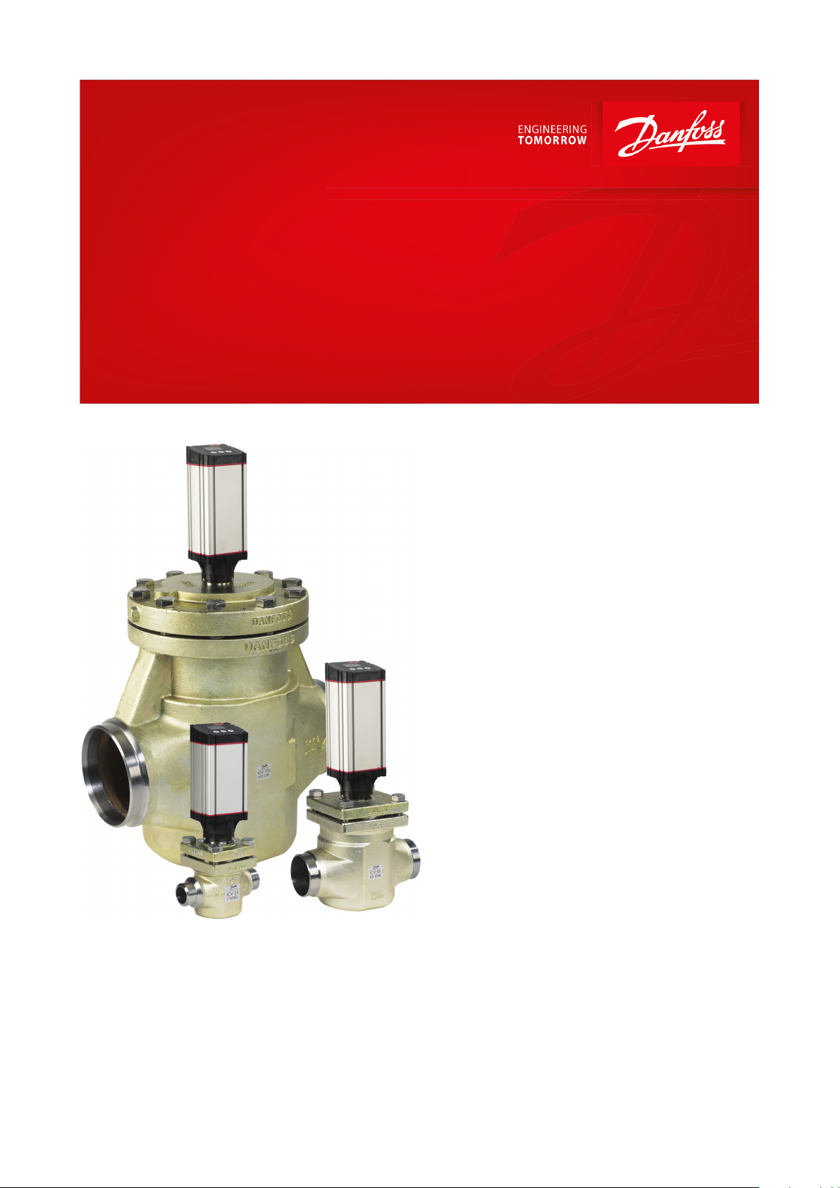
Motor operated valves and Actuators
Type ICM and ICAD
ICM motor valve equipped with ICAD actuator provides a higher
suction pressure, and a much better COP, ultimately leading
to signicant energy savings
ICM motor operated valves belong to the ICV
family and are one of two product groups.
ICV types
• ICS - Pilot operated servo valve
• ICM - Motor operated vave
The motor operated valve comprises four main
components: Valve body, top cover, function
module and Actuator. On ICM 20 – 65 the top
cover and function module will be combined.
ICM are motor operated valves driven by
actuator type ICAD.
ICM valves are designed to regulate an
expansion process in liquid lines with or
without phase change or control pressure or
temperature in dry and wet suction lines and
hot gas lines. ICM valves are designed so that
the opening and closing forces are balanced,
therefore, only two sizes of ICAD actuators are
needed for the complete range of ICM from DN
20 to DN 150. The ICM motor operated valve
and ICAD actuator assembly oers a very
compact unit with small dimensions.
ICAD
Actuator types ICAD 600A and 1200A are
dedicated for use with ICM motor operated
valves. There are only two sizes of ICAD
actuators that cover the range of valves from
ICM 20 to ICM 150.
The ICAD is controlled via a modulating
analogue signal (e.g. 4 – 20 mA / 2 – 10 V) or a
digital ON / OFF signal. ICAD incorporates an
advanced MMI (Man Machine Interface),
including continuous display of Opening
Degree, which gives the user a very advanced
and exible setup procedure that can meet
many dierent applications.
AI236186442940en-001201
Page 2

Motor operated valves and Actuators, type ICM and ICAD
Features
ICM valve
• Designed for Industrial Refrigeration applications for a maximum working pressure of 52 bar / 754 psig
• Applicable to HCFC, HFC, R717 (Ammonia) and R744 (CO2)
• Direct coupled connections
• Connection types include butt weld, socket weld, solder and threaded connections
• Low temperature steel body
• Low weight and compact design
• V-port regulating cone ensures optimum regulating accuracy particularly at part load
• Cavitation resistant valve seat on A cones
• Modular Concept
◦ Each valve body is available with several dierent connection types and sizes
◦ Valve overhaul is performed by replacing the function module (ICM 20 – 65)
◦ Possible to convert ICM motor operated valve to ICS pilot operated servo valve
◦ Spare parts available for ICM 100 – 150
• Manual opening possible via ICAD or Multifunction tool
• PTFE seat provides excellent valve tightness
• Magnet coupling - real hermetic sealing
• ICAD 600A / 1200A include encoder function that will provide a true valve position feedback to Danfoss controller
or non-Danfoss control systems
• Classication: DNV, CRN, BV, EAC etc. To get an updated list of certication on the products please contact your
local Danfoss Sales Company
ICAD actuator
• Designed for industrial refrigeration installations
• Advanced and high speed Digital Stepper Motor Technology
• Seven segment LCD display and three programming keys included
• Valve opening degree can be observed continuously
• Can easily be congured to dierent applications on-site (change speed, ON / OFF, Fail Safe operation, modulating
valve, etc..)
• Open – Close time: 3 – 45 seconds depending on valve size
• Modulating, ON / OFF operation or Neutral zone / 3 point control
• Multiple speed selection during operation
• Logging of old alarms
• Password protection
• Control input signal :
◦ 4 – 20 mA, 0 – 20 mA, 0 – 10 V, 2 – 10 V.
◦ One or two digital inputs
• Position feed back : 0 – 20 mA, 4 – 20 mA (ICM)
• 3 Digital ON / OFF feedback
• Resolution: 20 micron / step (0.02 mm stroke pr. step)
• Total steps: 250 – 3650 depending on size
• Auto Calibration, Neutral zone
• In the event of a power failure, multiple fail safe options are possible. During power failure, ICM can be selected to:
◦ Close ICM
◦ Open ICM
◦ Stay in the same position, as when power failure occurs
◦ Go to a specic ICM valve opening degree
• Hermetic magnetic motor
• Enclosure: IP67 ~ NEMA 6
• Approvals: CE, UL, CRN
• Connectors for easy installation and servicing
• ICAD 600A / 1200A ensures an acurate feedback on the valve position
© Danfoss | Climate Solutions | 2021.12 AI236186442940en-001201 | 2
Page 3
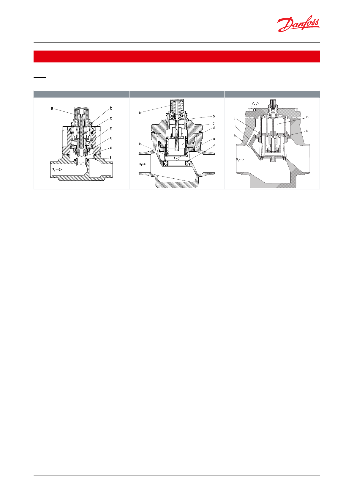
ICM 20
ICM 25-65
ICM 100 – 150
P
2
k
h
i
j
Motor operated valves and Actuators, type ICM and ICAD
Functions
ICM
Table 1: ICM valves
ICM, motor operated valves are designed for use with the ICAD actuator with Display.
The driving force from the actuator is transferred via a magnetic coupling (a) through the stainless steel top housing
(b) and thus eliminates the need for a packing gland. The rotational movement of the magnetic coupling (a) is
transferred to a spindle (c) which in turn provides the vertical movement of the piston (d) and the valve seat (e), to
open and close the valve. The closing force of the actuator, combined with the the valve seat (e) and PTFE valve
plate (f ), provides an eective seal to prevent leakage across the valve port, when the valve is in the closed position.
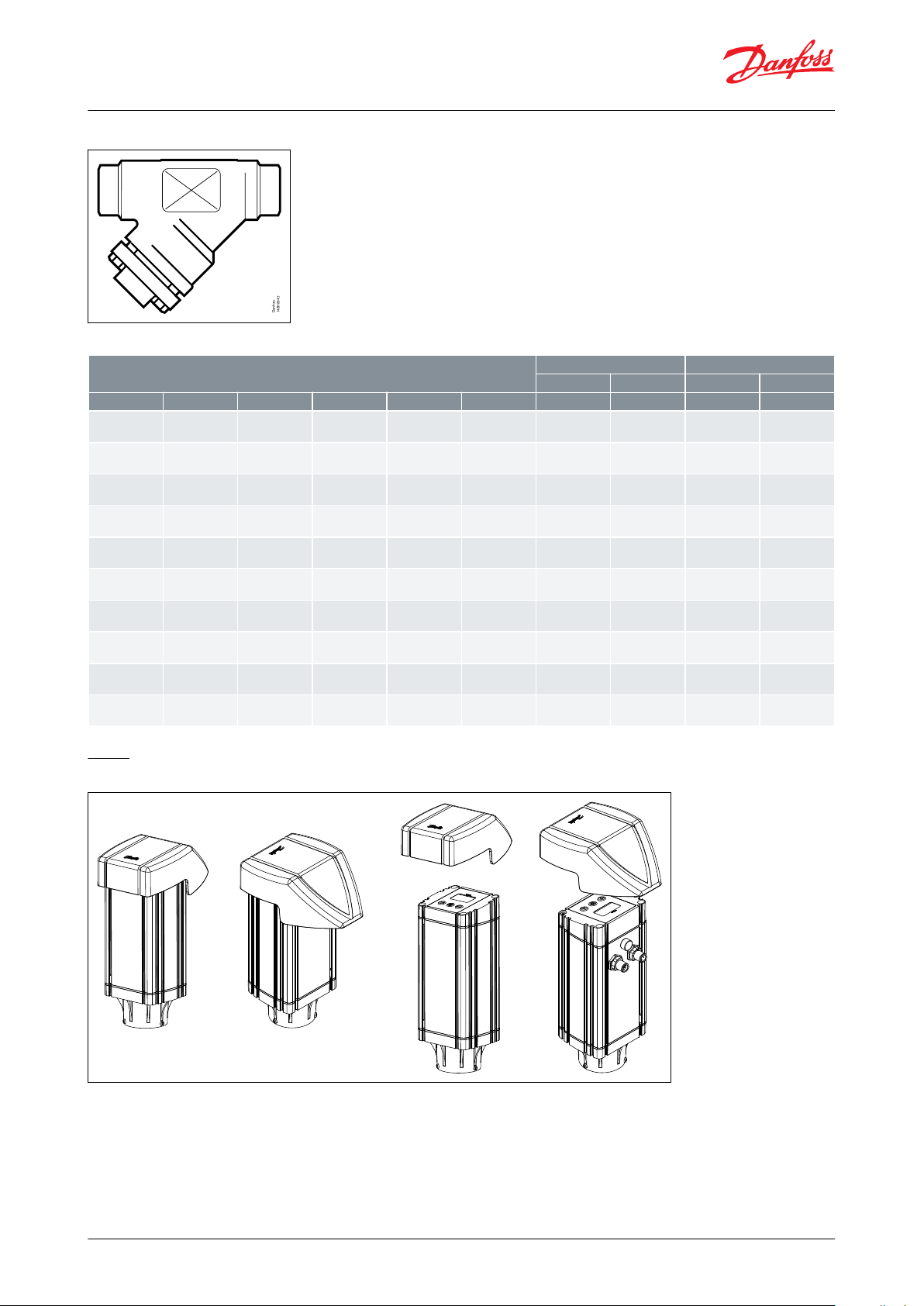
To prevent damage to the PTFE valve seat (e) and plate (f ) from system debris, it is recommended that a lter is
installed upstream of the valve. Please refer to page 14 for lter sizing and application recommendations.
ICM 20 – 65:
Valve inlet pressure (P1) acting on the underside of the PTFE valve seat (e) also passes through the hollow piston
assembly (d) on to the top of the piston (d) and balances the pressure acting on the piston (d). Any trapped liquid
across the throttle cone (g) is allowed to equalise down to the valve outlet without aecting the valve performance.
ICM 100 – 150:
Valve inlet pressure (P1) acting on the underside of the PTFE valve plate (h) also passes through the equalization
hole (i) and ensures that the servo piston (j) is pressure balanced. This will equalize P1 and P2. During an opening
operation of the valve, the pilot piston (k) will be raised from its valve seat inside the servo piston (j). This allows the
P2 pressure to escape through the servo piston (j) to the outlet of the valve. The pressure P1 will act on the
underside of the servo piston (j) and force it to open. This will close the gap between the pilot piston (k) and the
servo piston (j) until the pressures P1 and P2 are equalized again. When there is no pressure dierence between P1
and the outlet of the valve the pilot piston (k) is attached to the servo piston (j) ensuring it to open up.
ICAD
There are two sizes of ICAD actuator that covers the range of valves from ICM 20 to ICM 150. The actuators have a
fully weather protected enclosure with none of the moving parts exposed to the environment.
The fast acting actuators and balanced valve design results in the valve being able to move from the fully closed to
the fully open position in between 3 to 45 seconds depending on valve size and ICAD setup.
Each body may be tted with multiple function / top cover to give dierent capacities
© Danfoss | Climate Solutions | 2021.12 AI236186442940en-001201 | 3
Page 4

Type
Valve body size
kv (m3/h)
Cv (US
gal/min
)
ICM 20A-33
20
0.2
0.23
ICM 20-A
0.6
0.7
ICM 20-B66
1.6
1.9
ICM 20-B
2.4
2.8
ICM 20-C
4.6
5.3
ICM 25-A2567ICM 25-A33
2
2.3
ICM 25-B1213.9
ICM 32-A329
10.4
ICM 32-B1720
ICM 40-A401517ICM 40-B2630
ICM 50-A502327ICM 50-B4046
ICM 65-A653541ICM 65-B7081
ICM 100-B
100
142
167
ICM 125-B
125
223
260
ICM 150-B
150
370
430
Motor operated valves and Actuators, type ICM and ICAD
Figure 1: Multiple function / top cover
Table 2: Multiple function / top cover with capacities
ICAD
The design of ICAD is based on a digital stepper motor technology combined with an advanced MMI (Man Machine
Interface), that gives excellent possibilities for having a high degree of exibility with the same type of ICAD
actuator.
At the ICAD display the Opening Degree (0 – 100 %) of the actual ICM valve installed can be continuously observed.
The advanced menu system will allow several parameters to be ajusted to obtain the required function.
Many dierent parameters can be congurated, among these:
• Modulating, ON / OFF operation or Neutral zone / 3 point control
• Analog input
◦ 0 – 20 mA or 4 – 20 mA
◦ 0 – 10 V or 2 – 10 V
• Digital Input
◦ ICAD can be congured to support one or two digital inputs
◦ When using one digital input, 0 – 10 V can not be used at the same time
◦ By using two digital inputs at Neutral zone / 3 point control, the analog input (0/2 – 10 V, 0/4 – 20 mA) and
Analog Output (0/4 – 20 mA) can not be used at the same time
• Analog output
◦ 0 – 20 mA or 4 – 20 mA
• Automatic or manual control
• Change of ICM valve speed
• Automatic calibration
• Multiple Fail Safe set-up options during power cut
© Danfoss | Climate Solutions | 2021.12 AI236186442940en-001201 | 4
Page 5
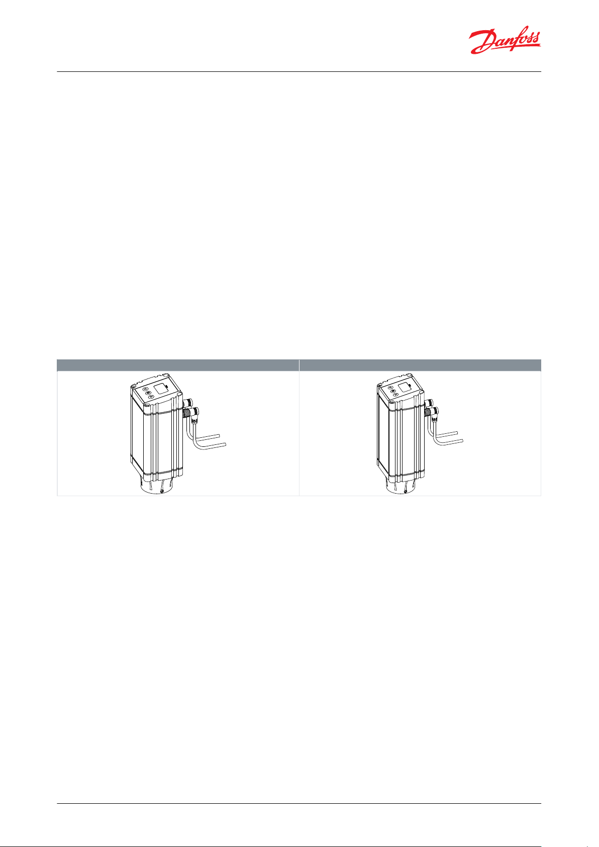
ICAD 600A
ICAD 1200A
Motor operated valves and Actuators, type ICM and ICAD
For service all Input and Output signals can be recalled and observed from the ICAD display.
A password protection has been linked to the parameter of entering the correct ICM valve to avoid unintentional
and non-authorised operation.
ICAD can manage and display dierent alarms. If an alarm has been detected the display will alternate between
showing: Actual alarm present and Opening Degree of ICM valve. If more than one alarm is active at the same time
the alarm with the highest priority will take preference. The alarm with the highest priority is shown on the display.
All alarms will automatically reset when disappearing.
Previous alarms can be recalled for traceability and service purposes.
Any active alarm will activate the common digital alarm output. All alarms will automatically reset when
disappearing.
ICAD provides two digital output signals to 3rd party control equipment (e.g. PLC) indicating if the ICM valve is
completely open or completely closed.
The hermetic magnetic motor coupling makes it easy to dismount the ICAD from ICM valve.
A magnetic coupled actuator is easily installed. Only two actuators are needed to cover the entire ICM
program
Table 3: ICAD 600A and ICAD 1200A
© Danfoss | Climate Solutions | 2021.12 AI236186442940en-001201 | 5
Page 6
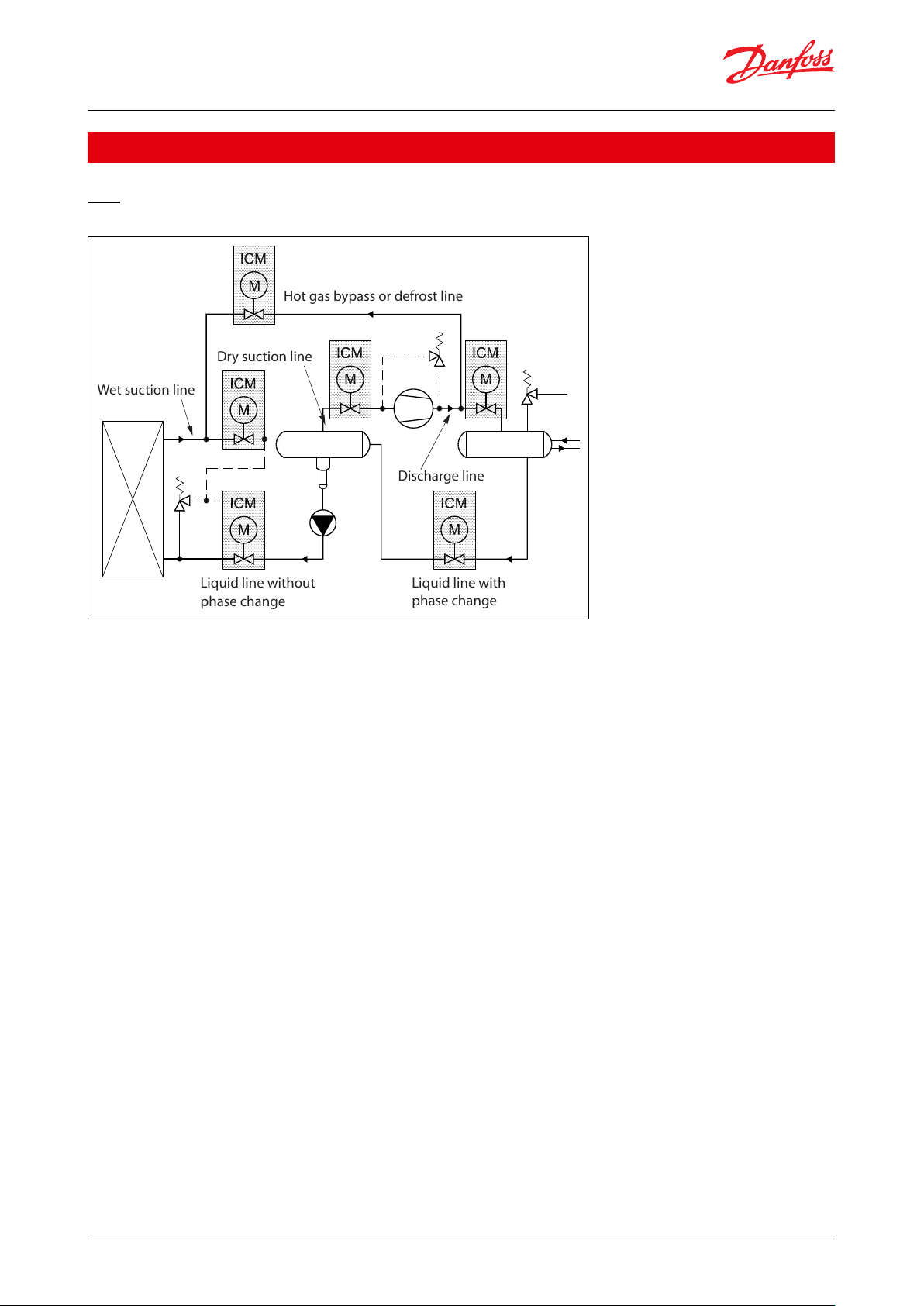
Hot gas bypass or defrost line
Dry suction line
Wet suction line
Liquid line without
phase change
Liquid line with
phase change
Discharge line
Motor operated valves and Actuators, type ICM and ICAD
Applications
ICM
Figure 2: ICM Application
NOTE:
ICM can be used for pressure and temperature regulation in dry and wet suction lines, in hot gas lines and in liquid
lines with or without phase change (i.e. where no expansion occurs in the valve).
Valve capacities for dierent refrigerants and applications are given in the following tables. Selection of ICM / ICS
valves will be available with the DIRcalc ver. 1.3 selection program and later. The resultant valve selections will be:ICMEXP for expansion valve functions and where the selection criteria has been predened for expansion valve
application: ICM will be for control valve functions and will include for all available function modules as valve
pressure drop is the main consideration for valve selection.
The process for identifying the ICM valve solution can be determined from the ordering pages. Initially select the
nominal valve size, identify the required valve body and connection types, followed by the module insert and then
the correct actuator to suit the module insert and valve body.
As the ICM and ICS valves use a common body it is possible to install the body without having previously
determined whether a servo or motor function is required. A blank top cover complete with xing screws can be
supplied to allow for pressure testing.
In applications where the ICM is used to control pressure / temperature at diering operating conditions e.g. dual
temperature store, the ICM must be selected so that the full operating conditions (minimum and maximum
capacity / summer and winter conditions) are within the control range of the selected ICM valve.
It is particularly important to ensure that the ICM valve selection is not oversized and as a consequence operates at
a minimum opening degree, which can result in a hunting condition and continuous recalibration of the ICM valve.
NOTE:
ICM valves should be sized to suit required capacity and operating conditions. ICM valves should not be line sized.
For ICM 20 – 65 applications it is recommended that the valve opening degree at the minimum operating
conditions is greater than 5%.
For ICM 100 – 150 applications it is recommended that the valve opening degree at the minimum operating
conditions is greater than 10%.
© Danfoss | Climate Solutions | 2021.12 AI236186442940en-001201 | 6
Page 7
Danfoss
148H8045
Recommended lters
Filter element for liquid line
Filter element for suction line
150 mesh
100 mesh
72 mesh
38 mesh
Filter Type
SizeDA
FPT
SOC
100 my
150 my
250 my
500 my
FIA Straight-
way
20 (
3
⁄4 in.)
148B5343
148B5347
148B5349
148B5348
148H3122
148H3124
148H3126
148H3128
FIA Straight-
way
25 (1 in.)
148B5443
148B5447
148B5449
148B5448
148H3123
148H3125
148H3127
148H3129
FIA Straight-
way
32 (1
1
⁄4 in.)
148B5544
148B5552
148B5549
148B5548
148H3123
148H3125
148H3127
148H3129
FIA Straight-
way
40 (1
1
⁄2 in.)
148B5625
148B5644
148B5645
148H3123
148H3125
148H3127
148H3129
FIA Straight-
way
50 (2 in.)
148B5713
148B5716
148B5717
148H3157
148H3130
148H3138
148H3144
FIA Straight-
way
65 (2
1
⁄2 in.)
148B5813
148B5815
148H3131
148H3139
148H3145
FIA Straight-
way
80 (3 in.)
148B5906
148B5908
148H3119
148H3120
148H3121
FIA Straight-
way
100 (4 in.)
148B6007
148B6009
148H3132
148H3140
148H3146
FIA Straight-
way
125 (5 in.)
148B6106
148B6108
148H3133
148H3141
148H3147
FIA Straight-
way
150 (6 in.)
148B6203
148B6205
148H3134
148H3142
148H3148
Motor operated valves and Actuators, type ICM and ICAD
Figure 3: Filter
Table 4: Recommended lters
ICAD
Figure 4: ICAD protection cap
ICAD protection cap
For all outdoor applications or where extra protection of the display and keyboard is needed, Danfoss recommends
using the ICAD protection cap.
The protection cap will give the ICAD display and keyboard an extra protection against e.g. sun radiation or other
impacts from the surrounding environment. Furthermore it protects the cable connectors against inappropriate
loads.
© Danfoss | Climate Solutions | 2021.12 AI236186442940en-001201 | 7
Page 8
Motor operated valves and Actuators, type ICM and ICAD
The special designed protection cap can be mounted on all ICAD 600A / 1200A.
The installation of the protection cap is done by sliding the protection cap down on the top of the ICAD. To secure
the protection cap, tie it to the connector cables using the hole in the protection cap.
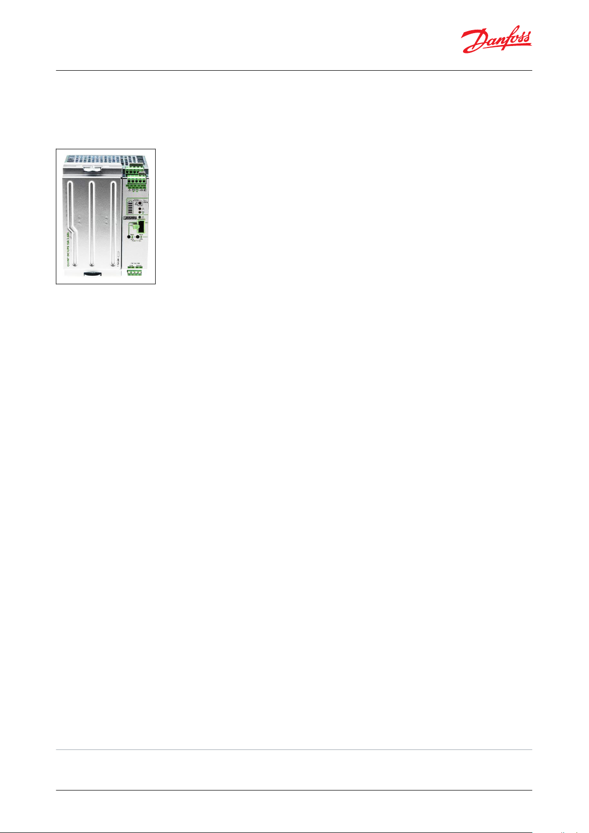
Figure 5: ICAD-UPS for ICM 20 – 150
ICAD-UPS for ICM 20 – 150
ICAD-UPS is dedicated for use along with ICM sizes 20 - 150 installed with ICAD 600A and ICAD 1200A actuators.
In the event of power failure, there is a need to make sure that the ICM goes to a safe position.
ICAD-UPS can be connected to the ICAD 600A / 1200A.
The solution ICM with ICAD connected to ICADUPS will give one of the following possibilities in the event of power
failure:
• close ICM
• open ICM
• stay
• go to a specec ICM Opening Degree
When power supply has been re-established the system will automatically return to normal operation.
Facts and features
• Industrial product
• Can support up to
◦ 3 pcs. of ICAD 1200A or
◦ 8 pcs. of ICAD 600A
• Integrated solution - battery and UPS
• Industrial approvals:
◦ CE, UL
DIN rail mounting
•
• LED status indication
• 24 V DC supply → Same transformer as for ICAD can be used
• Continuous monitoring of battery
• Integrated temperature sensor for optimized battery charging
• Adjustable buer time
(1)
. (1, 2, 3, 5, 10, 15, 20 or innity) = Ensures longer life time of the battery
• Forced remote shutdown in buer mode via digital input
• 3 digital volt free relay change over contacts for signals to PLC systems. (Power OK, Buer mode (failsafe supply to
ICAD), Alarm).
Code number: 027H0388
For further information please see the instruction ICAD-UPS
1
Buer time is dened as the period where ICAD is only powered from the ICAD-UPS (i.e. not from main supply). On ICAD-UPS there is an
adjustable buer time setting (1, 2, 3, 5, 10, 15, 20, 30 min. or innity). If set to 3, ICAD-UPS will switch o power to connected ICAD 600A /
1200A, 3 minutes after the power failure occurs. This ensures that the internal battery inside ICAD-UPS do not fully discharge.
© Danfoss | Climate Solutions | 2021.12 AI236186442940en-001201 | 8
Page 9
+
-
+
-
CAD-U
S
maximum
8 pcs. of ICAD 600 or maximum3 pcs. of ICAD 1200
Input Output
Black
White
Brown
Black
White
Brown
+
+
-
DC 24 V
DC 24 V
ICAD-UPS
+
-
CAD-U S
maximum 8 pcs. of ICAD 600 or maximum3 pcs. of ICAD 1200
Input Output
Black
White
Brown
Black
White
Brown
+
+
-
DC 24 V
ICAD-UPS
Motor operated valves and Actuators, type ICM and ICAD
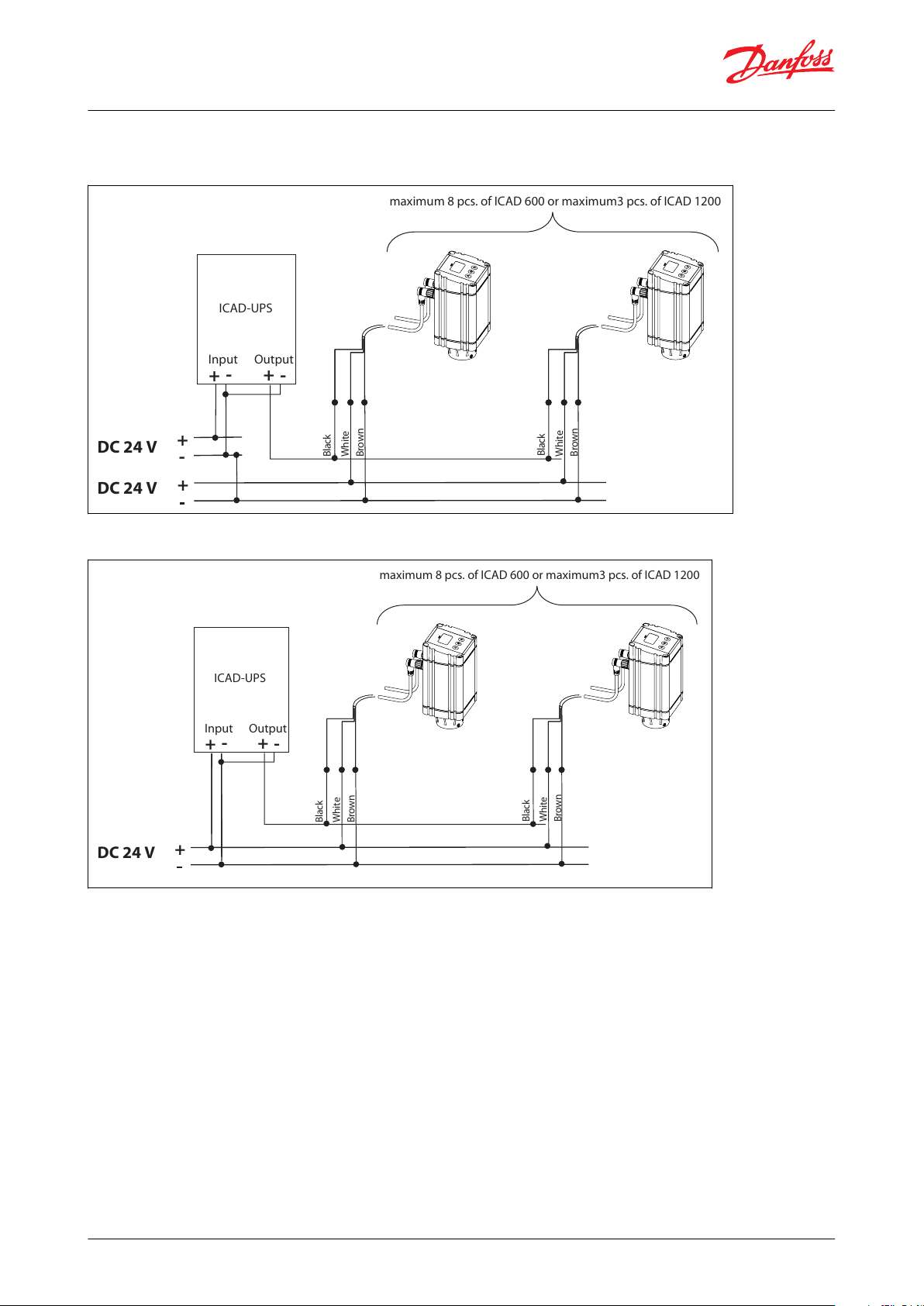
ICAD-UPS applications
Figure 6: Seperate 24 V DC tranformer for both ICAD-UPS and ICAD 600A / 1200A
Figure 7: One 24 V DC tranformer for ICAD-UPS and ICAD 600A / 1200A
© Danfoss | Climate Solutions | 2021.12 AI236186442940en-001201 | 9
Page 10

Motor operated valves and Actuators, type ICM and ICAD
Media
Refrigerants
ICM 20, ICM 100, ICM 125 and ICM 150:
Applicable to HCFC, non ammable HFC, R717 (Ammonia) and R744 (CO2).
ICM 25-65:
Applicable to HCFC, non ammable HFC, R717 (Ammonia), R744 (CO2) and R1234ze.
Use with ammable hydrocarbons cannot be recommended. For further information please contact your local
Danfoss sales company.
New refrigerants
Danfoss products are continually evaluated for use with new refrigerants depending on market requirements.
When a refrigerant is approved for use by Danfoss, it is added to the relevant portfolio, and the R number of the
refrigerant (e.g. R513A) will be added to the technical data of the code number. Therefore, products for specic
refrigerants are best checked at store.danfoss.com/en/, or by contacting your local Danfoss representative.
© Danfoss | Climate Solutions | 2021.12 AI236186442940en-001201 | 10
Page 11

Description
Values
Media temperature range
Media: -60 / +120 °C (-76 / +248 °F)
Max. working pressure
52 bar / 754 psi g
Description
Values
Temperature range (ambient)
-30 / +50 °C (-22 / +122 °F)
Enclosure
IP 67 (~NEMA 6)
ICAD 600A
ICAD 1200A
ICM 20
ICM 40
ICM 25
ICM 50
ICM 32
ICM 65
Motor operated valves and Actuators, type ICM and ICAD
Product specication
Pressure and temperature data
ICM
Table 5: Pressure and temperature data
Max. openening pressure dierential (MOPD)
• ICM 20-32: 52 bar / 750 psi
• ICM 40: 40 bar / 580 psi
• ICM 50: 30 bar / 435 psi
• ICM 65: 20 bar / 290 psi
• ICM 100 20 bar / 290 psi
• ICM 125 20 bar / 290 psi
• ICM 150 20 bar / 290 psi
Time to move from Closed to Open position or in reverse order with maximum selected speed at ICAD
• ICM 20: 3 Sec.
• ICM 25: 7 Sec.
• ICM 32: 8 Sec.
• ICM 40: 10 Sec.
• ICM 50: 13 Sec.
• ICM 65: 13 Sec.
• ICM 100: 25 Sec.
• ICM 125: 35 Sec.
• ICM 150: 45 Sec.
IMPORTANT:
When used in liquid refrigerant above 75 °C / 167 °F, please contact Danfoss.
ICAD
Table 6: Pressure and temperature data
Design
ICM
Valve body and top cover material
Low temperature steel
Surface protection
ICM 20 – 150: The external surface is zinc-chromated to provide good corrosion protection.
ICAD
ICAD 600A and ICAD 1200A can be used together with following Danfoss valves.
Table 7: Valve and actuator combination
© Danfoss | Climate Solutions | 2021.12 AI236186442940en-001201 | 11
Page 12
ICAD 600A
ICAD 1200A
ICM 100
ICM 125
ICM 150
ICV 20
ICV 25
ICV 32
ICV 40
ICV 50
ICV 65
ICV 100
ICV 125
ICV 150
Motor operated valves and Actuators, type ICM and ICAD
Materials
Housing
Aluminium
Top part of ICAD
PBT thermo plastic
Weight
• ICAD 600A: 1.2 kg / 2.64 lb
• ICAD 1200A: 1.9 kg / 4.19 lb
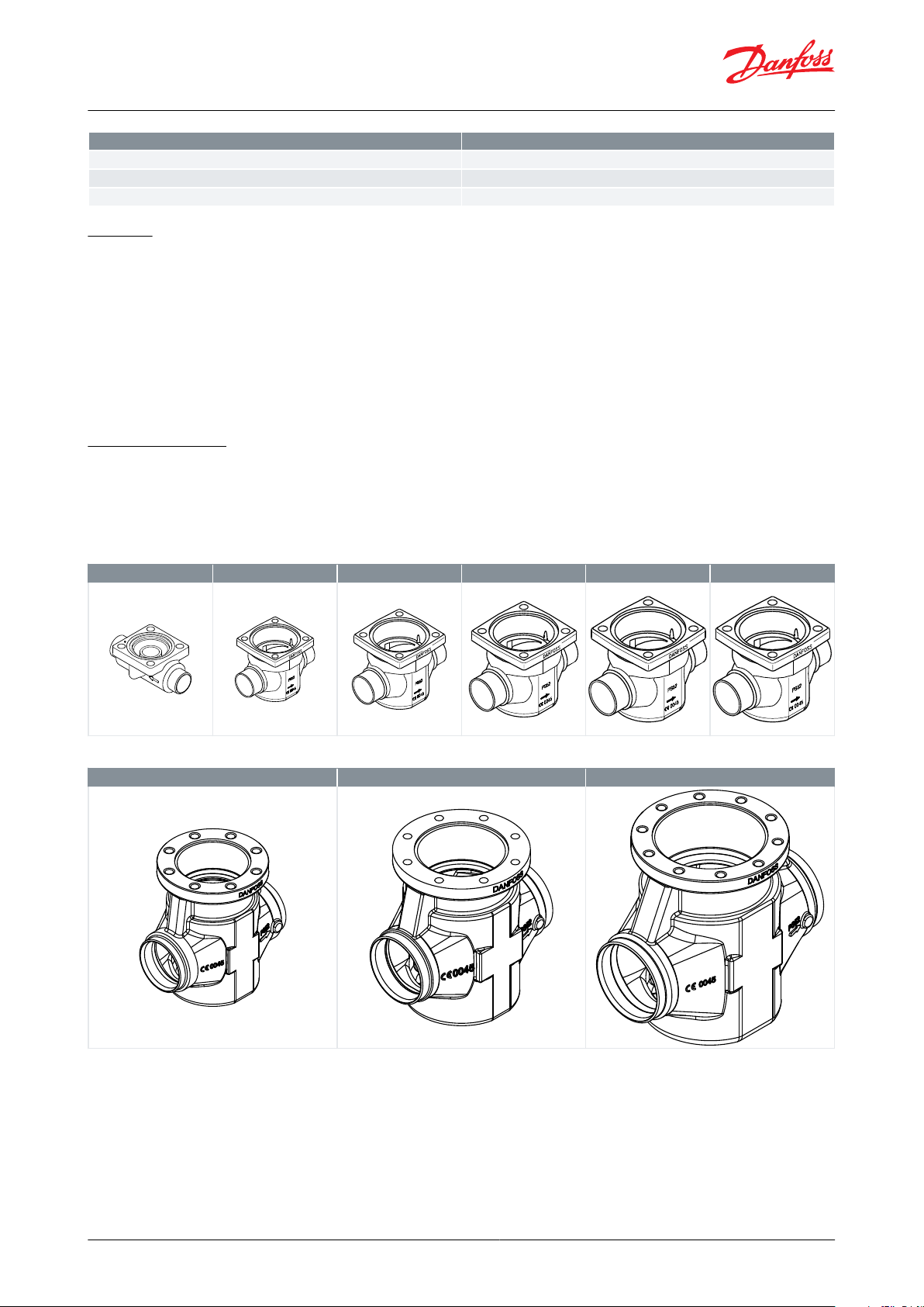
The ICM Concept
The ICM concept is developed around a modular principle. This gives the possibility of combining function modules
and top covers with special valve body size that is available in a variety of connection possibilities.
There are nine valve bodies available.
Table 8: Valve sizes
Table 9: Valve sizes
Valve bodies in the sizes ICV 20 – ICV 65 are available with a range of undersizes through oversized connection sizes
and types.
ICV 100 – ICV 150 are available in butt-weld DIN and butt-weld ANSI nominal sizes.
© Danfoss | Climate Solutions | 2021.12 AI236186442940en-001201 | 12
Page 13

DAJ
SOCSDSA
FPT
Butt-weld DIN
Butt-weld ANSI
Butt-weld JIS
Socket weld ANSI
Solder DIN
Solder ANSI
Female Pipe Thread
Actuator
ICAD 600A
ICAD 1200A
Valve size
ICM 20
ICM 40
ICM 25
ICM 50
ICM 32
ICM 65
-
ICM 100
-
ICM 125
-
ICM 150
Motor operated valves and Actuators, type ICM and ICAD
Table 10: Connections
ICM motor and ICAD actuator combinations
The ICM motor operated valve and ICAD actuator combinations are as follows:
Table 11: Valve and actuator combination
ICAD 600A / ICAD 1200A
ICAD actuators can be controlled using the following signals:
• 0 – 20 mA
• 4 – 20 mA (default)
• 0 – 10 V
• 2 – 10 V
• One or two digital Input
ICAD actuators can operate an ICM valve as an On / O function supported by one digital input.
ICAD actuators can operate an ICM valve as Neutral zone / 3 point control supported by two digital inputs.
The ICM valve can be operated manually via the ICAD actuator or the Multi-function tool for ICM (see the ordering
section).
Fail Safe supply options
In the event of a power failure, multiple fail safe options are possible, provided that a ICAD-UPS or similar is used.
During power failure, ICM can be selected to:
• Close ICM
• Open ICM
• Stay in the same position, as when power failure occurs
• Go to a specic ICM valve opening degree
See the section ICAD UPS for further information.
NOTE:
A fail safe supply (battery or UPS) is required.
Electrical
ICAD
Electrical connection
Connection to ICAD is done via M12 connectors. ICAD has two M12 male connectors build-in:
Power supply:
4 poled M12 male connector
© Danfoss | Climate Solutions | 2021.12 AI236186442940en-001201 | 13
Page 14
Prefabricated ICAD cable length Code
number
1.5 m
027H0426
3 m
027H0438
10 m
027H0427
15 m
027H0435
24 Volt DC
ONLY
Voltage ICAD terminal
(600A / 1200A) [V DC]
Min.21222324
Max.
26.4
Motor operated valves and Actuators, type ICM and ICAD
Control signals:
8 poled M12 male connector
ICAD can be delivered with (1.5 m. / 60 in.) or without cables with M12 female connectors:
Power Supply cable with 4 poled M12 female connector: 3 x 0.34 mm2 (3 x ~22 AWG)
Control cable with 8 poled M12 female connector: 7 x 0.25 mm2 (7 x ~24 AWG)
Cable set with M12 female connectors in other lengths are available. See the section "Spare parts and accessories".
Please observe cable voltage drop
Distance between the applied DC transformer and the ICAD terminal box may cause a voltage drop. Cross section of
cables and size of DC transformer must be calculated so that the voltage at all time at the ICAD terminal box
(2)
,
both during standstill and during operation of ICAD, is within this range:
Table 12: Voltage at all time at the ICAD terminal box
Supply voltage is galvanic isolated from Input/Output
Supply voltage: see Table 12
Load:
• ICAD 600A: 1.2 A
• ICAD 1200A: 2.0 A
Fail safe supply: See Table 12
Load:
• ICAD 600A: 1.2 A
• ICAD 1200A: 2.0 A
Analogue Input - Current or Voltage
• Current: 0/4 – 20 mA
• Load: 200 W
• Voltage: 0/2 – 10 V DC
• Load : 10 kW
Analogue Output:
• Current: 0/4 – 20 mA
• Load : ≤ 250 W
Digital Input
Digital ON / OFF input by means of volt-free contact (Signal / Telecom relays with goldplated contacts
recommended) – Voltage input used
ON: Contact impedance < 50 W )
OFF: Contact impedance > 100 k W
Digital Output
• 3 pcs. NPN transistor output
• External supply:5 – 24 V DC (Same supply as for ICAD can be used, but please note that the galvanically isolated
system will then be spoiled)
• Output load: 50 W
• Load: Max. 50 mA
2
Do not measure inside the ICAD itself
© Danfoss | Climate Solutions | 2021.12 AI236186442940en-001201 | 14
Page 15
Type
ICAD 600A
Speed Parameter i04
ICM 20
ICM 25
ICM 32
Max. (i04 = 100)
2 mAh
5 mAh
5 mAh
Min. (i04 = 1)
200 mAh
467 mAh
533 mAh
ICAD 1200A
Speed Parameter i04
ICM 40
ICM 50
ICM 65
Max. (i04 = 100)
17 mAh
22 mAh
22 mAh
Min. (i04 = 1)
1667 mAh
2167 mAh
2167 mAh
ICAD 1200A
Speed Parameter i04
ICM 100
ICM 125
ICM 150
Max. (i04 = 100)
54 mAh
65 mAh
76 mAh
Min. (i04 = 1)
5318 mAh
6351 mAh
7501 mAh
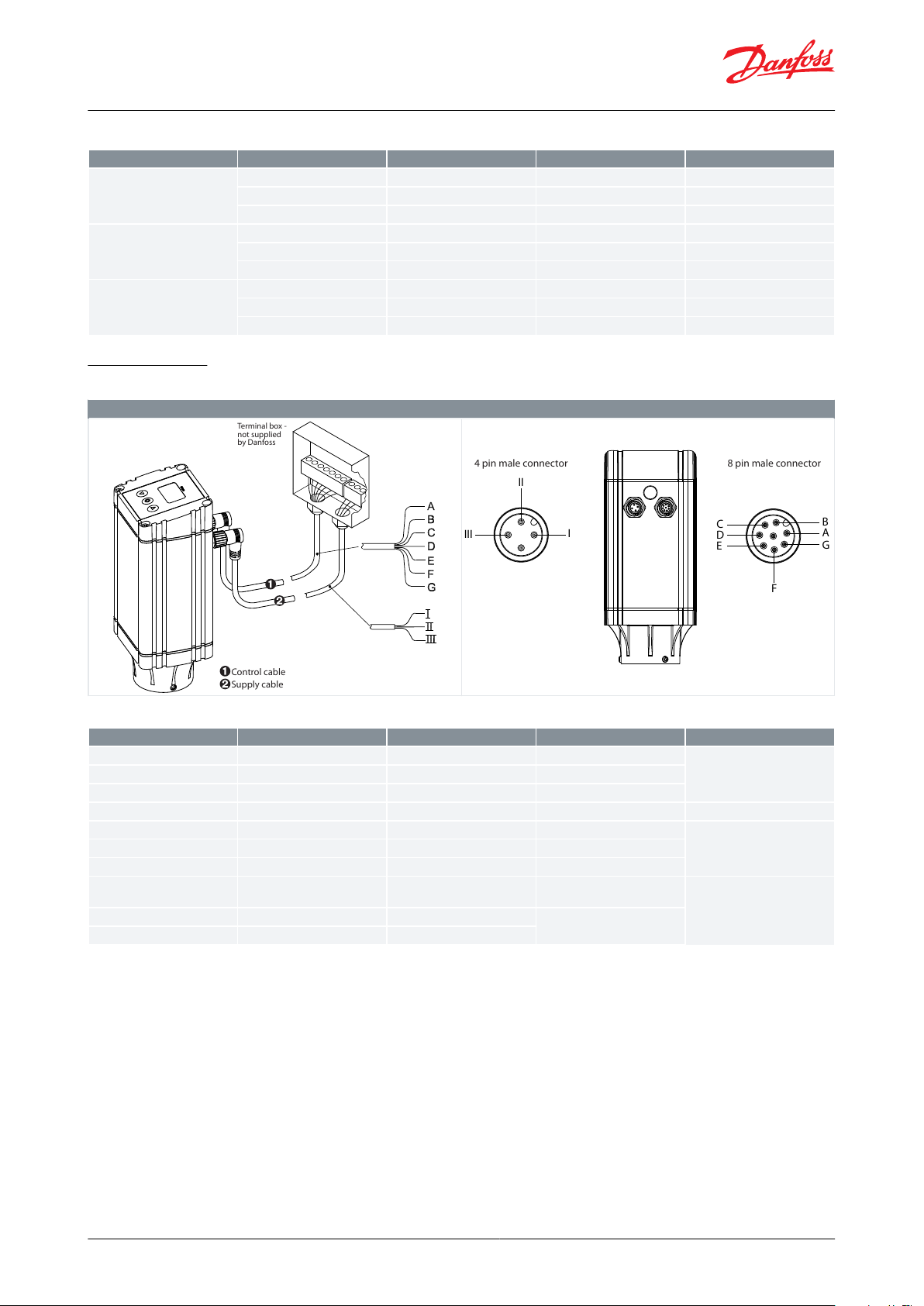
Cable connection - Two 1.5 m / 60 in. cables pre-mounted
Control cable
Supply cable
Terminal box -
not supplied
by Danfoss
III
I
II
C
D
E
B
A
G
F
4 pin male connector
8 pin male connector
Ref.
Colour
Description
A
Black
–
Common Alarm
Digital Ouput
B
Brown
–
ICM fully open
C
Red
–
ICM fully closed
D
Orange
–
GND ground
E
Yellow
+
0/4 – 20 mA Input
(2)
Analogue In/Output
F
Green
+
0/2 – 10 V Input
(3)
G
Blue
+
0/4 – 20 mA Output
(2)
I
Black
+
Fail safe supply Battery / UPS
(4)
19 V DCIIWhite
+
Supply voltage 24 V DC
III
Brown
–
Motor operated valves and Actuators, type ICM and ICAD
Table 13: Battery capacity: For each open / closed cycle
Cable connection
Table 14: Cable connection - Two 1.5 m / 60 in. cables pre-mounted
Table 15: Cable connection
(2)
(2)
If Neutral zone / 3 point control is selected (parameter i02 = 3) then E and G are used as DI2 - Digital ON / OFF input
If Neutral zone / 3 point control is selected (parameter i02 = 3) then E and G are used as DI2 - Digital ON / OFF input
(3)
(3)
Also used with D (GND, ground) for DI1 - Digital ON-OFF operation
Also used with D (GND, ground) for DI1 - Digital ON-OFF operation
(4)
(4)
Uninterruptable Power Supply
Uninterruptable Power Supply
NOTE:
Colour code changed when compared to older colour wiring diagram.
© Danfoss | Climate Solutions | 2021.12 AI236186442940en-001201 | 15
Page 16
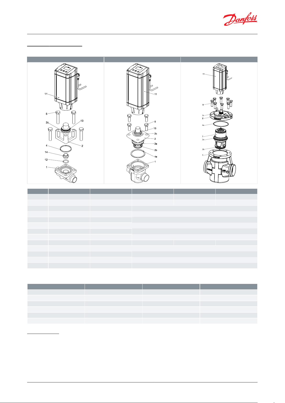
ICM 20
ICM 25-65
ICM 100 – 150
2c
4a
2a
2b
3
No.
Part
Material
EN
ASTM
JIS
1
Housing
Low temperature steel
G20Mn5QT, EN 10213-3
LCC, A352
SCPL1, G5151
2
Top cover
Low temperature steel
G20Mn5QT, EN 10213-3
LCC, A352
SCPL1, G5151
2a
O-ring
Chloroprene (Neoprene)
2b
O-ring
Chloroprene (Neoprene)
2c
O-ring
Chloroprene (Neoprene)
3
Function module
4
Gasket
Chloroprene (Neoprene)
4a
Gasket
Fiber, non-asbestos
5
Bolts
Stainless steel
A2-70, EN 1515-1
Grade B8 A320
A2-70, B 1054
11
Actuator
12
O-ring
Chloroprene (Neoprene)
13
O-ring
Chloroprene (Neoprene)
14
Seat
High density polymer
Type
Screw
Type
Screw
ICM 20
M10 × 55 A2-70 DIN 931
ICM 100
M20 × 60 A2-70 DIN 933
ICM 25
M12 × 30 A2-70 DIN 933
ICM 125
M20 × 60 A2-70 DIN 933
ICM 32
M14 × 35 A2-70 DIN 933
ICM 150
M20 × 70 A2-70 DIN 933
ICM 40
M14 × 35 A2-70 DIN 933
ICM 50
M16 × 40 A2-70 DIN 933
ICM 65
M16 × 40 A2-70 DIN 933
Motor operated valves and Actuators, type ICM and ICAD
Material specication
Table 16: ICM specication
NOTE:
Table 17: Bolt sizes (pos. 5)
Connections
There is a very wide range of connection types available with ICM valves:
• D: Butt weld, EN 10220
• A: Butt weld, ANSI (B 36.10)
• J: Butt weld, JIS (B S 602)
• SOC: Socket weld, ANSI (B 16.11)
© Danfoss | Climate Solutions | 2021.12 AI236186442940en-001201 | 16
Page 17

DAJ
SOCSDSA
FPT
Butt-weld DIN
Butt-weld ANSI
Butt-weld JIS
Socket weld ANSI
Solder DIN
Solder ANSI
Female Pipe Thread
Size
SizeØDTØDTmmin.mmmm
in.
in.
20
(
3
⁄4)
26.9
2.3
1.059
0.091251
33.7
2.6
1.327
0.103321
1
⁄4
42.4
2.6
1.669
0.102401
1
⁄2
48.3
2.6
1.902
0.103502
60.3
2.9
2.37
0.11652
1
⁄2
76.1
2.930.11803
88.9
3.2
3.5
0.13
1004114.3
3.6
4.5
0.14
1255140.745.5
0.16
1506168.3
6.3
6.6
0.25
Size
SizeØDTØDT
Schedulemmin.mmmm
in.
in.
-20
3
⁄4
26.941.059
0.15880-25133.7
4.6
1.327
0.18180-32
1
1
⁄4
42.4
4.9
1.669
0.19380-40
1
1
⁄2
48.3
5.1
1.902
0.20180-50260.3
3.9
2.37
0.1540-65
2
1
⁄2
73
5.2
2.87
0.240-80388.9
5.5
3.5
0.2240-1004114.364.5
0.24
-1255140.7
6.5
5.5
0.26
-1506168.3
7.1
6.6
0.28
Size
SizeØDTØDTmmin.mmmm
in.
in.
-20
3
⁄4
26.941.059
0.158
-25133.7
4.6
1.327
0.181
-32
1
1
⁄4
42.4
4.9
1.669
0.193
-40
1
1
⁄2
48.3
5.1
1.902
0.201
-50260.3
3.9
2.37
0.15
-65
2
1
⁄2
76.3
5.230.2
-80388.9
5.5
3.5
0.22
Motor operated valves and Actuators, type ICM and ICAD
• SD: Solder connection, EN 1254-1
• SA: Solder connection, ANSI (B 16.22)
• FPT: Female pipe thread (ANSI/ASME B 1.20.1)
Table 18: Connections
Table 19: D: Butt-weld DIN (2448)
Table 20: A: Butt-weld ANSI (B 36.10)
Table 21: J: Butt-weld JIS
© Danfoss | Climate Solutions | 2021.12 AI236186442940en-001201 | 17
Page 18

Size
SizeIDTIDTLLmmin.mmmm
in.
in.mmin.
-20
3
⁄4
27.2
4.6
1.071
0.181130.51
-25133.9
7.2
1.335
0.284130.51
-32
1
1
⁄4
42.7
6.1
1.743
0.24130.51
-40
1
1
⁄2
48.8
6.6
1.921
0.26130.51
-50261.2
6.2
2.41
0.24160.63
-65
2
1
⁄2
74
8.8
2.91
0.344160.63
SizeIDLmmmm
mm
16
16.071522
22.08
16.52828.082635
35.072542
42.072854
54.093376
76.1
33
SizeIDL
in.
in.
in.
5
⁄8
0.625
0.591
7
⁄8
0.875
0.65
1
1
⁄8
1.125
1.024
1
3
⁄8
1.375
0.984
1
5
⁄8
1.625
1.102
2
1
⁄8
2.125
1.3
2
5
⁄8
2.625
1.3
Size
Size
Inside pipe thread
mm
in.
-20
3
⁄4
(
3
⁄4 x 14 NPT)
-25
1
(1 x 11.5 NPT)
-32
1
1
⁄4
(1
1
⁄4 x 11.5 NPT)
Motor operated valves and Actuators, type ICM and ICAD
Table 22: SOC: Socket welding ANSI (B 16.11)
Table 23: SD: Soldering (DIN 2856)
Table 24: SA: Soldering (ANSI B 16.22)
Table 25: FPT: Female pipe thread, (ANSI/ASME B 1.20.1)
Dimensions and weights
ICM 20 / ICAD 600A
Figure 8: ICM 20 / ICAD 600A
© Danfoss | Climate Solutions | 2021.12 AI236186442940en-001201 | 18
Page 19

Connection
H
H1H
2
L
L1L
2
Weight ICM
incl. ICAD
20 D (
3
⁄4 in.)
mm4019585107
102653 kg
in.
1.58
7.68
3.35
4.21
4.02
2.56
6.6 lb.
25 D (1 in.)
mm4019585107
102653 kg
in.
1.58
7.68
3.35
4.21
4.02
2.56
6.6 lb.
25 A (1 in.)
mm4019585107
102653 kg
in.
1.58
7.68
3.35
4.21
4.02
2.56
6.6 lb.
20 A (
3
⁄4 in.)
mm4019585107
102653 kg
in.
1.58
7.68
3.35
4.21
4.02
2.56
6.6 lb.
20 SOC (
3
⁄4 in.)
mm4019585107
102653 kg
in.
1.58
7.68
3.35
4.21
4.02
2.56
6.6 lb.
16 SD (
5
⁄8 in.)
mm4019585107
102653 kg
in.
1.58
7.68
3.35
4.21
4.02
2.56
6.6 lb.
22 SD (
7
⁄8 in.)
mm4019585107
102653 kg
in.
1.58
7.68
3.35
4.21
4.02
2.56
6.6 lb.
16 SA (
5
⁄8 in.)
mm4019585107
102653 kg
in.
1.58
7.68
3.35
4.21
4.02
2.56
6.6 lb.
22 SA (
7
⁄8 in.)
mm4019585107
102653 kg
in.
1.58
7.68
3.35
4.21
4.02
2.56
6.6 lb.
20 FPT (
3
⁄4 in.)
mm4019585107
102653 kg
in.
1.58
7.68
3.35
4.21
4.02
2.56
6.6 lb.
Connection
H
H1H
2
L
L1L
2
Weight ICM
incl. ICAD
20 D (
3
⁄4 in.)
mm4019599135
102844.1 kg
in.
1.58
7.68
3.9
5.31
4.02
3.31
8.8 lb.
25 D (1 in.)
mm4019599135
102844.1 kg
in.
1.58
7.68
3.9
5.31
4.02
3.31
8.8 lb.
32 D (1
1
⁄4 in.)
mm4019599135
102844.1 kg
in.
1.58
7.68
3.9
5.31
4.02
3.31
8.8 lb.
40 D (1
1
⁄2 in.)
mm4019599135
102844.1 kg
in.
1.58
7.68
3.9
5.31
4.02
3.31
8.8 lb.
20 A (
3
⁄4 in.)
mm4019599135
102844.1 kg
in.
1.58
7.68
3.9
5.31
4.02
3.31
8.8 lb.
Motor operated valves and Actuators, type ICM and ICAD
Table 26: ICM 20 / ICAD 600A
NOTE:
D = Butt-weld DIN ; A = Butt-weld ANSI ; SOC = Socket weld ANSI ; SD = Solder DIN ; SA = Solder ANSI ; FPT =
Female Pipe Thread
ICM 25 / ICAD 600A
Figure 9: ICM 25 / ICAD 600A
Table 27: ICM 25 / ICAD 600A
© Danfoss | Climate Solutions | 2021.12 AI236186442940en-001201 | 19
Page 20

Connection
H
H1H
2
L
L1L
2
Weight ICM
incl. ICAD
25 A (1 in.)
mm4019599135
102844.1 kg
in.
1.58
7.68
3.9
5.31
4.02
3.31
8.8 lb.
32 A (1
1
⁄4 in.)
mm4019599135
102844.1 kg
in.
1.58
7.68
3.9
5.31
4.02
3.31
8.8 lb.
20 SOC (
3
⁄4 in.)
mm4019599135
102844.1 kg
in.
1.58
7.68
3.9
5.31
4.02
3.31
8.8 lb.
25 SOC (1 in.)
mm4019599148
102844.1 kg
in.
1.58
7.68
3.9
5.83
4.02
3.31
8.8 lb.
22 SD (
7
⁄8 in.)
mm4019599135
102844.1 kg
in.
1.58
7.68
3.9
5.31
4.02
3.31
8.8 lb.
28 SD (1
1
⁄8 in.)
mm4019599147
102844.1 kg
in.
1.58
7.68
3.9
5.79
4.02
3.31
8.8 lb.
22 SA (
7
⁄8 in.)
mm4019599135
102844.1 kg
in.
1.58
7.68
3.9
5.31
4.02
3.31
8.8 lb.
28 SA (1
1
⁄8 in.)
mm4019599147
102844.1 kg
in.
1.58
7.68
3.9
5.79
4.02
3.31
8.8 lb.
35 SD (1
3
⁄8 in.
SA)
mm4019599147
102844.1 kg
in.
1.58
7.68
3.9
5.79
4.02
3.31
8.8 lb.
20 FPT (
3
⁄4 in.)
mm4019599135
102844.1 kg
in.
1.58
7.68
3.9
5.31
4.02
3.31
8.8 lb.
25 FPT (1 in.)
mm4019599135
102844.1 kg
in.
1.58
7.68
3.9
5.31
4.02
3.31
8.8 lb.
Connection
H
H1H
2
L
L1L
2
Weight ICM
incl. ICAD
32 D (1
1
⁄4 in.)
mm40195
117
145
102
102
5.8 kg
in.
1.58
7.68
4.61
5.71
4.02
4.02
11.0 lb.
40 D (1
1
⁄2 in.)
mm40195
117
145
102
102
5.8 kg
in.
1.58
7.68
4.61
5.71
4.02
4.02
11.0 lb.
32 A (1
1
⁄4 in.)
mm40195
117
145
102
102
5.8 kg
in.
1.58
7.68
4.61
5.71
4.02
4.02
11.0 lb.
40 A (1
1
⁄2 in.)
mm40195
117
145
102
102
5.8 kg
in.
1.58
7.68
4.61
5.71
4.02
4.02
11.0 lb.
Motor operated valves and Actuators, type ICM and ICAD
NOTE:
D = Butt-weld DIN ; A = Butt-weld ANSI ; SOC = Socket weld ANSI ; SD = Solder DIN ; SA = Solder ANSI ; FPT =
Female Pipe Thread
ICM 32 / ICAD 600A
Figure 10: ICM 32 / ICAD 600A
Table 28: ICM 32 / ICAD 600A
© Danfoss | Climate Solutions | 2021.12 AI236186442940en-001201 | 20
Page 21

Connection
H
H1H
2
L
L1L
2
Weight ICM
incl. ICAD
32 SOC (1
1
⁄4 in.)
mm40195
117
147
102
102
5.8 kg
in.
1.58
7.68
4.61
5.79
4.02
4.02
11.0 lb.
35 SD (1
3
⁄8 in.
SA)
mm40195
117
148
102
102
5.8 kg
in.
1.58
7.68
4.61
5.83
4.02
4.02
11.0 lb.
42 SD (1
5
⁄8 in.)
mm40195
117
148
102
102
5.8 kg
in.
1.58
7.68
4.61
5.83
4.02
4.02
11.0 lb.
42 SA (1
5
⁄8 in.)
mm40195
117
148
102
102
5.8 kg
in.
1.58
7.68
4.61
5.83
4.02
4.02
11.0 lb.
Connection
H
H1H
2
L
L1L
2
Weight ICM
incl. ICAD
40 D (1
1
⁄2 in.)
mm45219
131
160
102
107
7.8 kg
in.
1.77
8.62
5.16
6.3
4.02
4.21
17.2 lb.
50 D (2 in.)
mm45219
131
180
102
107
7.8 kg
in.
1.77
8.62
5.16
7.09
4.02
4.21
17.2 lb.
40 A (1
1
⁄2 in.)
mm45219
131
160
102
107
7.8 kg
in.
1.77
8.62
5.16
6.3
4.02
4.21
17.2 lb.
50 A (2 in.)
mm45219
131
180
102
107
7.8 kg
in.
1.77
8.62
5.16
7.09
4.02
4.21
17.2 lb.
40 SOC (1
1
⁄2 in.)
mm45219
131
180
102
107
7.8 kg
in.
1.77
8.62
5.16
7.09
4.02
4.21
17.2 lb.
42 SD (1
5
⁄8 in.)
mm45219
131
180
102
107
7.8 kg
in.
1.77
8.62
5.16
7.09
4.02
4.21
17.2 lb.
42 SA (1
5
⁄8 in.)
mm45219
131
180
102
107
7.8 kg
in.
1.77
8.62
5.16
7.09
4.02
4.21
17.2 lb.
Motor operated valves and Actuators, type ICM and ICAD
NOTE:
D = Butt-weld DIN ; A = Butt-weld ANSI ; SOC = Socket weld ANSI ; SD = Solder DIN ; SA = Solder ANSI
ICM 40 / ICAD 1200A
Figure 11: ICM 40 / ICAD 1200A
Table 29: ICM 40 / ICAD 1200A
NOTE:
D = Butt-weld DIN ; A = Butt-weld ANSI ; SOC = Socket weld ANSI ; SD = Solder DIN ; SA = Solder ANSI
© Danfoss | Climate Solutions | 2021.12 AI236186442940en-001201 | 21
Page 22

Connection
H
H1H
2
L
L1L
2
Weight ICM
incl. ICAD
50 D (2 in.)
mm45219
159
200
102
125
11.1 kg
in.
1.77
8.62
6.26
7.87
4.02
4.92
24.4 lb.
65 D (2
1
⁄2 in.)
mm45219
159
210
102
125
11.1 kg
in.
1.77
8.62
6.26
8.27
4.02
4.92
24.4 lb.
50 A (2 in.)
mm45219
159
200
102
125
11.1 kg
in.
1.77
8.62
6.26
7.87
4.02
4.92
24.4 lb.
65 A (2
1
⁄2 in.)
mm45219
159
210
102
125
11.1 kg
in.
1.77
8.62
6.26
8.27
4.02
4.92
24.4 lb.
50 SOC (2 in.)
mm45219
159
216
102
125
11.1 kg
in.
1.77
8.62
6.26
8.5
4.02
4.92
24.4 lb.
54 SD (2
1
⁄8 in.
SA)
mm45219
159
216
102
125
11.1kg
in.
1.77
8.62
6.26
8.5
4.02
4.92
24.4 lb.
Motor operated valves and Actuators, type ICM and ICAD
ICM 50 / ICAD 1200A
Figure 12: ICM 50 / ICAD 1200A
Table 30: ICM 50 / ICAD 1200A
NOTE:
D = Butt-weld DIN ; A = Butt-weld ANSI ; SOC = Socket weld ANSI ; SD = Solder DIN
ICM 65 / ICAD 1200A
Figure 13: ICM 65 / ICAD 1200A
© Danfoss | Climate Solutions | 2021.12 AI236186442940en-001201 | 22
Page 23

Connection
H
H1H
2
L
L1L
2
Weight ICM
incl. ICAD
65 D (2
1
⁄2 in.)
mm45219
188
230
102
139
16.6 kg
in.
1.77
8.62
7.4
9.06
4.02
5.47
36.5 lb
80 D (3 in.)
mm45219
188
245
102
139
16.6 kg
in.
1.77
8.62
7.4
9.65
4.02
5.47
36.5 lb
65 A (2
1
⁄2 in.)
mm45219
188
230
102
139
16.6 kg
in.
1.77
8.62
7.4
9.06
4.02
5.47
36.5 lb
80 A (3 in.)
mm45219
188
245
102
139
16.6 kg
in.
1.77
8.62
7.4
9.65
4.02
5.47
36.5 lb
65 J (2
1
⁄2 in.)
mm45219
188
230
102
139
16.6 kg
in.
1.77
8.62
7.4
9.06
4.02
5.47
36.5 lb
65 SOC (2
1
⁄2 in.)
mm45219
188
230
102
139
16.6 kg
in.
1.77
8.62
7.4
9.06
4.02
5.47
36.5 lb
76 SD (3 in.)
mm45219
188
245
102
139
16.6 kg
in.
1.77
8.62
7.4
9.65
4.02
5.47
36.5 lb
67 SA (2
5
⁄8 in.)
mm45219
188
245
102
139
16.6 kg
in.
1.77
8.62
7.4
9.65
4.02
5.47
36.5 lb
H1
H
L
B1
B
H2
Connection
H
H1H
2
L
B
B
2
Weight ICM
incl. ICAD
100 D/A (4 in.)
mm
321
23845295
175
102
44 kg.
in.
12.64
9.37
1.77
11.61
6.89
4.02
97 lb.
Motor operated valves and Actuators, type ICM and ICAD
Table 31: ICM 65 / ICAD 1200A
NOTE:
D = Butt-weld DIN ; A = Butt-weld ANSI ; J = Butt-weld JIS ; SOC = Socket weld ANSI ; SD = Solder DIN ; SA =
Solder ANSI
ICM 100 / ICAD 1200A
Figure 14: ICM 100 / ICAD 1200A
Table 32: ICM 100 / ICAD 1200A
NOTE:
D = Butt-weld DIN ; A = Butt-weld ANSI
© Danfoss | Climate Solutions | 2021.12 AI236186442940en-001201 | 23
Page 24

B
B1
L
H1
H
H2
Connection
H
H1H
2
L
B
B
2
Weight ICM
incl. ICAD
125 D/A (5 in.)
mm
365
23845350
215
102
55 kg
in.
14.37
9.37
1.77
13.78
8.47
4.02
121 lb.
L
H H1
H2
B
B1
Connection
H
H1H
2
L
B
B
1
Weight ICM
incl. ICAD
150 D/A (6 in.)
mm
443
23845445
255
102
95 kg
in.
17.77
9.37
1.77
17.52
10.04
4.02
209 lb.
Motor operated valves and Actuators, type ICM and ICAD
ICM 125 / ICAD 1200A
Figure 15: ICM 125 / ICAD 1200A
Table 33: ICM 125 / ICAD 1200A
NOTE:
D = Butt-weld DIN ; A = Butt-weld ANSI
ICM 150 / ICAD 1200A
Figure 16: ICM 150 / ICAD 1200A
Table 34: ICM 150 / ICAD 1200A
NOTE:
D = Butt-weld DIN ; A = Butt-weld ANSI
NOTE:
Weight presented in tables 26 to 34 is approximated only
© Danfoss | Climate Solutions | 2021.12 AI236186442940en-001201 | 24
Page 25

Valve body 22 SD (
7
⁄8 in.)
027H1154
Table 36
Top cover/function mod‐
ule
ICM 20-B
027H1181
Table 37
Actuator
027H9075
Table 38
20 D (
3
⁄4 in.)
25 D (1 in.)
20 A (
3
⁄4 in.)
20 SOC (
3
⁄4 in.)
027H1145
027H1163
027H1148
027H1151
16 SA (
5
⁄8 in.)
22 SA (
7
⁄8 in.)
16 SD (
5
⁄8 in.)
22 SD
7
⁄8 in.)
027H1129
027H1160
027H1132
027H1154
20 FPT (
3
⁄4 in.)
25 A (1 in.)
027H1157
027H1166
Motor operated valves and Actuators, type ICM and ICAD
Ordering
Ordering from the parts programme
ICM 20 / ICAD 600A
Table 35: Example (select from table I, II and III)
Figure 17: ICV 20 valve body
Table 36: ICV 20 valve body w/dierent connections Table I
NOTE:
D = Butt-weld DIN ; A = Butt-weld ANSI ; J = Butt-weld JIS ; SOC = Socket weld ANSI ; SD = Solder DIN ; SA =
Solder ANSI ; FPT = Female Pipe Thread
Figure 18: ICM 20
© Danfoss | Climate Solutions | 2021.12 AI236186442940en-001201 | 25
Page 26

Description
Code Number
ICM 20-A33
027H1186
(1)
ICM 20-A
027H1180
(1)
ICM 20-B66
027H1194
(1)
ICM 20-B
027H1181
(1)
ICM 20-C
027H1182
(1)
Description
Code Number
ICAD 600A with 1.5 m. / 60 in. cables
027H9075
ICAD 600A without cables
027H9120
Available connections
Type
20 D (
3
⁄4 in.)
25 D (1 in.)
20 A (
3
⁄4 in.)
20 SOC (
3
⁄4
in.)
16 SA (
5
⁄8 in.)
22 SA (
7
⁄8 in.)
16 SD (
5
⁄8 in.)
22 SD (
7
⁄8 in.)
20 FPT (
3
⁄4
in.)
25 A (1 in.)
ICM 20-A
027H1030
027H1020
027H1035
027H1040
(2)
027H1050
(2)
027H1045
(2)
(2)
ICM 20-B
027H1031
027H1021
027H1036
027H1041
(2)
027H1051
(2)
027H1046
(2)
(2)
ICM 20-C
027H1032
027H1022
(2)
(2)
(2)
027H1052
(2)
027H1047
(2)
027H1025
Motor operated valves and Actuators, type ICM and ICAD
Table 37: ICM 20 Function module / top cover Table II
(1)
(1)
Bolts and O-ring (for assembly with ICV valve body) Seat and O-ring (for seat to be mounted in ICV valve body)
Bolts and O-ring (for assembly with ICV valve body) Seat and O-ring (for seat to be mounted in ICV valve body)
Figure 19: Actuator ICAD 600A
Table 38: Actuator ICAD 600A Table III
Ordering complete factory assembled valve without actuator
Figure 20: Valve without actuator
Table 39: Body, function module/top cover Table A
(2)
(2)
Select from parts programme
Select from parts programme
© Danfoss | Climate Solutions | 2021.12 AI236186442940en-001201 | 26
Page 27

Valve body 32 D (1
1
⁄4 in.)
027H2129
Table 41
Top cover/function mod‐
ule
ICM 25-B
027H2181
Table 42
Actuator
027H9075
Table 43
20 D (
3
⁄4 in.)
25 D (1 in.)
32 D (1
1
⁄4 in.)
40 D (1
1
⁄2 in.)
027H2128
027H2120
027H2129
027H2135
35 SD (1
3
⁄8 in. SA)
28 SA (1
1
⁄8 in.)
22 SA (
7
⁄8 in.)
28 SD (1
1
⁄8 in.)
027H2134
027H2126
027H2125
027H2124
22 SD (
7
⁄8 in.)
20 A (
3
⁄4 in.)
25 A (1 in.)
32 A (1
1
⁄4 in.)
027H2123
027H2131
027H2121
027H2130
20 SOC (
3
⁄4 in.)
25 SOC (1 in.)
20 FPT (
3
⁄4 in.)
25 FPT (1 in.)
027H2132
027H2122
027H2133
027H2127
Description
Code Number
ICM 25-A
027H2180
(1)
ICM 25-A33
027H2190
(1)
ICM 25-B
027H2181
(1)
Motor operated valves and Actuators, type ICM and ICAD
ICM 25 / ICAD 600A
Table 40: Example (select from table I, II and III)
Figure 21: ICV 25 valve body
Table 41: ICV 25 valve body w/dierent connections Table I
NOTE:
D = Butt-weld DIN ; A = Butt-weld ANSI ; J = Butt-weld JIS ; SOC = Socket weld ANSI ; SD = Solder DIN ; SA =
Solder ANSI ; FPT = Female Pipe Thread
Figure 22: ICM 25
Table 42: ICM 25 Function module / top cover Table II
(1)
(1)
Including gasket and O-rings
Including gasket and O-rings
© Danfoss | Climate Solutions | 2021.12 AI236186442940en-001201 | 27
Page 28

Description
Code Number
ICAD 600A with 1.5 m. / 60 in. cables
027H9075
ICAD 600A without cables
027H9120
Available connections
Type
20 D (
3
⁄4 in.)
25 D (1 in.)
32 D (1
1
⁄4 in.)
40 D (1
1
⁄2 in.)
35 SD (1
3
⁄8 in.
SA)
28 SA (1
1
⁄8 in.)
22 SA (
7
⁄8 in.)
28 SD (1
1
⁄8 in.)
ICM 25-A
(1)
027H2000
(1)
027H2016
027H2014
027H2012
027H2010
027H2008
ICM 25-B
(1)
027H2001
(1)
(1)
027H2015
027H2013
027H2011
027H2009
22 SD (
7
⁄8 in.)
20 A (
3
⁄4 in.)
25 A (1 in.)
32 A (1
1
⁄4 in.)
20 SOC (
3
⁄4 in.)
25 SOC (1 in.)
20 FPT (
3
⁄4 in.)
25 FPT (1 in.)
ICM 25-A
027H2006
(1)
027H2002
(1)
(1)
027H2004
(1)
(1)
ICM 25-B
027H2007
(1)
027H2003
(1)
(1)
027H2005
(1)
(1)
Valve body 40 D (1
1
⁄2 in.)
027H3125
Table 46
Top cover/function mod‐
ule
ICM 32-A
027H3180
Table 47
Actuator
027H9075
Table 48
Motor operated valves and Actuators, type ICM and ICAD
Figure 23: Actuator ICAD 600A
Table 43: Actuator ICAD 600A Table III
Ordering complete factory assembled valve without actuator
Figure 24: Valve without actuator
Table 44: Body, function module / top cover Table A
(1)
(1)
Select from parts programme
Select from parts programme
ICM 32 / ICAD 600A
Table 45: Example (select from table I, II and III)
© Danfoss | Climate Solutions | 2021.12 AI236186442940en-001201 | 28
Page 29

32 D (1
1
⁄4 in.)
40 D (1
1
⁄2 in.)
42 SA (1
5
⁄8 in.)
42 SD (1
5
⁄8 in.)
027H3120
027H3125
027H3127
027H3128
35 SD (1
3
⁄8 in. SA)
32 A (1
1
⁄4 in.)
32 SOC (1
1
⁄4 in.)
40 A (1
1
⁄2 in.)
027H3123
027H3121
027H3122
027H3126
Description
Code Number
ICM 32-A
027H3180
(1)
ICM 32-B
027H3181
(1)
Description
Code Number
ICAD 600A with 1.5 m. / 60 in. cables
027H9075
ICAD 600A without cables
027H9120
Motor operated valves and Actuators, type ICM and ICAD
Figure 25: ICV 32 valve body
Table 46: ICV 32 valve body w/dierent connections Table I
NOTE:
D = Butt-weld DIN ; A = Butt-weld ANSI ; J = Butt-weld JIS ; SOC = Socket weld ANSI ; SD = Solder DIN ; SA =
Solder ANSI ; FPT = Female Pipe Thread
Figure 26: ICM 32
Table 47: ICM 32 Function module / top cover Table II
(1)
(1)
Including gasket and O-rings
Including gasket and O-rings
Figure 27: Actuator ICAD 600A
Table 48: Actuator ICAD 600A Table III
Ordering complete factory assembled valve without actuator
© Danfoss | Climate Solutions | 2021.12 AI236186442940en-001201 | 29
Page 30

Available connections
32 D (1
1
⁄4 in.)
40 D (1
1
⁄2 in.)
42 SA (1
5
⁄8 in.)
42 SD (1
5
⁄8 in.)
35 SD (1
3
⁄8 in.
SA)
32 A (1
1
⁄4 in.)
32 SOC (1
1
⁄4 in.)
40 A (1
1
⁄2 in.)
ICM 32-A
027H3000
027H3012
027H3008
(2)
027H3006
027H3002
027H3004
(2)
ICM 32-B
027H3001
(2)
(2)
(2)
027H3007
027H3003
027H3005
(2)
Valve body A 40 (1
1
⁄2 in.)
027H4121
Table 51
Top cover/function mod‐
ule
ICM 40-A
027H4180
Table 52
Actuator
027H9077
Table 53
40 D (1
1
⁄2 in.)
50 D (2 in.)
42 SA (1
5
⁄8 in.)
42 SD (1
5
⁄8 in.)
027H4120
027H4126
027H4124
027H4123
40 A (1
1
⁄2 in.)
40 SOC (1
1
⁄2 in.)
50 A (2 in.)
027H4121
027H4122
027H4127
Motor operated valves and Actuators, type ICM and ICAD
Figure 28: Valve without actuator
Table 49: Body, function module / top cover Table A
(2)
(2)
Select from parts programme
Select from parts programme
ICM 40 / ICAD 1200A
Table 50: Example (select from table I, II and III)
Figure 29: ICV 40 valve body
Table 51: ICV 40 valve body w/dierent connections Table I
NOTE:
D = Butt-weld DIN ; A = Butt-weld ANSI ; J = Butt-weld JIS ; SOC = Socket weld ANSI ; SD = Solder DIN ; SA =
Solder ANSI ; FPT = Female Pipe Thread
© Danfoss | Climate Solutions | 2021.12 AI236186442940en-001201 | 30
Page 31

Description
Code Number
ICM 32-A
027H3180
(1)
ICM 32-B
027H3181
Description
Code Number
ICAD 1200A with 1.5 m. / 60 in. cables
027H9077
ICAD 1200A without cables
027H9122
Available connections
Type
40 D (1
1
⁄2 in.)
50 D (2 in.)
42 SA (1
5
⁄8 in.)
42 SD (1
5
⁄8 in.)
40 A (1
1
⁄2 in.)
40 SOC (1
1
⁄2 in.)
50 A (2 in.)
ICM 40-A
027H4000
027H4010
027H4006
027H4008
027H4002
027H4004
(2)
ICM 40-B
027H4001
(2)
027H4007
027H4009
027H4003
027H4005
(2)
Motor operated valves and Actuators, type ICM and ICAD
Figure 30: ICM 40
Table 52: ICM 40 Function module / top cover Table II
(1)
(1)
Including gasket and O-rings
Including gasket and O-rings
Figure 31: Actuator ICAD 1200A
Table 53: Actuator ICAD 1200A Table III
Ordering complete factory assembled valve without actuator
Figure 32: Valve without actuator
Table 54: Body, function module/top cover Table A
(2)
(2)
Select from parts programme
Select from parts programme
© Danfoss | Climate Solutions | 2021.12 AI236186442940en-001201 | 31
Page 32

Valve body 65 D (1
1
⁄2 in.)
027H5124
Table 56
Top cover/function mod‐
ule
ICM 50-A
027H4180
Table 57
Actuator
027H9077
Table 58
50 D (2 in.)
65 D (2
1
⁄2 in.)
54 SD (2
1
⁄8 in. SA)
50 A (2 in.)
027H5120
027H5124
027H5123
027H5121
50 SOC (2 in.)
65 A (2
1
⁄2 in.)
027H5122
027H5125
Description
Code Number
ICM 50-A
027H5180
(1)
ICM 50-B
027H5181
(1)
Motor operated valves and Actuators, type ICM and ICAD
ICM 50 / ICAD 1200A
Table 55: Example (select from table I, II and III)
Figure 33: ICV 50 valve body
Table 56: ICV 50 valve body w/dierent connections Table I
Figure 34: ICM 50
Table 57: ICM 50 Function module / top cover Table II
(1)
(1)
Including gasket and O-rings
Including gasket and O-rings
© Danfoss | Climate Solutions | 2021.12 AI236186442940en-001201 | 32
Page 33

Description
Code Number
ICAD 1200A with 1.5 m. / 60 in. cables
027H9077
ICAD 1200A without cables
027H9122
Available connections
Type
50 D (2 in.)
65 D (2
1
⁄2 in.)
54 SD (2
1
⁄8 in. SA)
50 A (2 in.)
50 SOC (2 in.)
65 A (2
1
⁄2 in.)
ICM 50-A
027H5000
027H5008
027H5006
027H5002
027H5004
(2)
ICM 50-B
027H5001
(2)
027H5007
027H5003
027H5005
(2)
Valve body 65 J (2
1
⁄2 in.)
027H6122
Table 61
Top cover/function mod‐
ule
ICM 65-B
027H6181
Table 62
Actuator
027H9077
Table 63
Motor operated valves and Actuators, type ICM and ICAD
Figure 35: Actuator ICAD 1200A
Table 58: Actuator ICAD 1200A Table III
Ordering complete factory assembled valve without actuator
Figure 36: Valve without actuator
Table 59: Body, function module / top cover Table A
(2)
(2)
Select from parts programme
Select from parts programme
ICM 65 / ICAD 1200A
Table 60: Example (select from table I, II and III)
© Danfoss | Climate Solutions | 2021.12 AI236186442940en-001201 | 33
Page 34

65 D (2
1
⁄2 in.)
65 A (2
1
⁄2 in.)
65 J (2
1
⁄2 in.)
80 D (3 in.)
027H6120
027H6121
027H6122
027H6126
80 A (3 in.)
67 SA (2
5
⁄8 in.)
76 SD (3 in.)
65 SOC (2
1
⁄2 in.)
027H6127
027H6125
027H6124
027H6123
Description
Code Number
ICM 65-A
027H6180
(1)
ICM 65-B
027H6181
(1)
Description
Code Number
ICAD 1200A with 1.5 m. / 60 in. cables
027H9077
ICAD 1200A without cables
027H9122
Motor operated valves and Actuators, type ICM and ICAD
Figure 37: ICV 65 valve body
Table 61: ICV 65 valve body w/dierent connections Table I
NOTE:
D = Butt-weld DIN ; A = Butt-weld ANSI ; J = Butt-weld JIS ; SOC = Socket weld ANSI ; SD = Solder DIN ; SA =
Solder ANSI ; FPT = Female Pipe Thread
Figure 38: ICM 65
Table 62: ICM 65 Function module / top cover Table II
(1)
(1)
Including gasket and O-rings
Including gasket and O-rings
Figure 39: Actuator ICAD 1200A
Table 63: Actuator ICAD 1200A Table III
Ordering complete factory assembled valve without actuator
© Danfoss | Climate Solutions | 2021.12 AI236186442940en-001201 | 34
Page 35

Available connections
Type
65 D (2
1
⁄2 in.)
65 A (2
1
⁄2 in.)
65 J (2
1
⁄2 in.)
80 D (3 in.)
80 A (3 in.)
67 SA (2
5
⁄8 in.)
76 SD (3 in.)
65 SOC (2
1
⁄2 in.)
ICM 65-A
027H6010
027H6012
(2)
(2)
(2)
(2)
(2)
(2)
ICM 65-B
027H6001
027H6003
(2)
(2)
(2)
027H6007
027H6009
027H6005
Available connections
Type
100 D (4 in.)
100 A (4 in.)
ICM 100
027H7130
027H7131
Description
Code Number
ICAD 1200A with 1.5 m. / 60 in. cables
027H9077
ICAD 1200A without cable
027H9122
Motor operated valves and Actuators, type ICM and ICAD
Figure 40: Valve without actuator
Table 64: Body, function module / top cover Table A
(2)
(2)
Select from parts programme
Select from parts programme
ICM 100
Complete factory assembled valve without actuator
Figure 41: Body, function module / top cover Figure 42: ICM 100 Valve body
Table 65: Body, function module / top cover
Figure 43: Actuator ICAD 1200A
Table 66: Actuator ICAD 1200A
ICM 125
Complete factory assembled valve without actuator
© Danfoss | Climate Solutions | 2021.12 AI236186442940en-001201 | 35
Page 36

Available connections
Type
125 D (5 in.)
125 A (5 in.)
ICM 125
027H7150
027H7151
Description
Code Number
ICAD 1200A with 1.5 m. / 60 in. cables
027H9077
ICAD 1200A without cable
027H9122
Available connections
Type
150 D (6 in.)
150 A (6 in.)
ICM 150
027H7170
027H7171
Motor operated valves and Actuators, type ICM and ICAD
Figure 44: Body, function module / top cover Figure 45: ICM 100 Valve body
Table 67: Body, function module / top cover
Figure 46: Actuator ICAD 1200A
Table 68: Actuator ICAD 1200A
ICM 150
Complete factory assembled valve without actuator
Figure 47: Body, function module / top cover Figure 48: ICM 100 Valve body
Table 69: Body, function module / top cover
© Danfoss | Climate Solutions | 2021.12 AI236186442940en-001201 | 36
Page 37

Description
Code Number
ICAD 1200A with 1.5 m. / 60 in. cables
027H9077
ICAD 1200A without cable
027H9122
Description
Code no.
ICV 25 PM Valve housing
027H2119
(1)
ICV 32 PM Valve housing
027H3129
(1)
ICV 40 PM Valve housing
027H4128
(1)
ICV 50 PM Valve housing
027H5127
(2)
ICV 65 PM Valve housing
027H6128
(2)
Motor operated valves and Actuators, type ICM and ICAD
Figure 49: Actuator ICAD 1200A
Table 70: Actuator ICAD 1200A
Accessories
ICV PM anged valve housings
Figure 50: ICV PM anged valve housings
ICV PM anged valve housings
ICV PM anged valve housings can replace the PM valves on already installed refrigeration systems.
Pressure range
The ICV PM valve housing is designed for a max. working pressure of 28 bar g / 406 psig and therefore a suitable
replacement for PM valves in the service market. They also oer the same drop-in dimensions as the PM valves.
Table 71: ICV PM anged valve housings
(1)
(1)
Includes ICV PM valve housing,
Includes ICV PM valve housing,
(2)
(2)
Includes ICV PM valve housing,
Includes ICV PM valve housing,
ange gaskets and ange bolts
ange gaskets and ange bolts
ange gaskets, ange bolts and ange nuts
ange gaskets, ange bolts and ange nuts
© Danfoss | Climate Solutions | 2021.12 AI236186442940en-001201 | 37
Page 38

PM
REMOVE
ICV PM
ICV PM
DROP IN
ICM
ICS
ICLX
CUSTOMIZE
Description
Code no.
ICV 25 (H)A4A Valve housing
027H2304
(1)
ICV 32 A4A Valve housing
027H3130
(1)
ICV 32 HA4A Valve housing
027H3131
(1)
ICV 40 (H)A4A Valve housing
027H4129
(1)
ICV 50 (H)A4A Valve housing
027H5128
(2)
ICV 65 (H)A4A Valve housing
027H6129
(2)
Motor operated valves and Actuators, type ICM and ICAD
Figure 51: ICV PM anged valve housings assembly
NOTE:
Function modules and top covers must be ordered separately (see the section Page 25).
ICV (H)A4A anged valve housings
Figure 52: ICV (H)A4A anged valve housings
ICV (H)A4A anged valve housings
ICV (H)A4A anged valve housings can replace the (H)A4A valves on already installed refrigeration systems.
The ICV (H)A4A anged valve housing provides an upgrade of the old motor valve types HMMR and HMMV to ICM
motorized valve as a drop-in solution.
Pressure range
The ICV (H)A4A valve housing is designed for a max. working pressure of 28 bar g / 406 psig and therefore a suitable
replacement for (H)A4A valves in the service market. They also oer the same drop-in dimensions as the (H)A4A
valves.
Table 72: ICV (H)A4A anged valve housings
(1)
(1)
Includes ICV PM valve housing,
Includes ICV PM valve housing,
(2)
(2)
Includes ICV PM valve housing,
Includes ICV PM valve housing,
ange gaskets and ange bolts
ange gaskets and ange bolts
ange gaskets, ange bolts and ange nuts
ange gaskets, ange bolts and ange nuts
© Danfoss | Climate Solutions | 2021.12 AI236186442940en-001201 | 38
Page 39

(H)A4A
REMOVE
ICV (H)A4A
ICV (H)A4A
DROP IN
ICM
ICS
ICLX
CUSTOMIZE
Description
Code Number
Repair kit
ICM 20-A / ICM 20-A-33 (Metal with plastic seat)
ICM 20-B / ICM 20-C (Plastic seat)
027H1190
Connectors for ICAD 600A / 1200A
Connector type
Code Number
Two Female Connectors with screw terminals:
• connector for power
• connector for control signals
027H0430
Motor operated valves and Actuators, type ICM and ICAD
Figure 53: ICV (H)A4A anged valve housings assembly
NOTE:
Function modules and top covers must be ordered separately (see the section Page 25).
ICM 20 / ICAD 600A
Figure 54: Repair kit
Table 73: Spare parts
Figure 55: Connectors
Table 74: Accessories
Figure 56: ICAD-UPS
© Danfoss | Climate Solutions | 2021.12 AI236186442940en-001201 | 39
Page 40

Description
Code Number
ICAD-UPS
027H0388
Description
Code Number
Multi-function tool
027H0180
Connectors for ICAD 600A / 1200A
Cable length
Code Number
Cable set 1.5 m, female
027H0426
Cable set 3 m, female
027H0438
Cable set 10 m, female
027H0427
Cable set 15 m, female
027H0435
Protection cap ICAD 600A / 1200A
Description
Code Number
Protection cap
027H0431
Motor operated valves and Actuators, type ICM and ICAD
Table 75: Accessories
Figure 57: Multi-function tool
Table 76: Accessories
Figure 58: Cable
Table 77: Accessories
Figure 59: Protection cap
Table 78: Accessories
NOTE:
Please observe, when used in CO2, that the o-rings on the ICM module can swell (grow). At service it is recommend
that new o-rings are installed before the ICM functions module again is installed in the ICV valve body.
© Danfoss | Climate Solutions | 2021.12 AI236186442940en-001201 | 40
Page 41

Description
Code Number
ICM 25 Inspection kit
027H2218
ICM 32 Inspection kit
027H3016
Connectors for ICAD 600A / 1200A
Connector type
Code Number
Two Female Connectors with screw terminals:
• connector for power
• connector for control signals
027H0430
Description
Code Number
ICAD-UPS
027H0388
Description
Code Number
Multi-function tool
027H0180
Motor operated valves and Actuators, type ICM and ICAD
ICM 25 – 32 / ICAD 600A
Figure 60: Inspection kit
Table 79: Spare parts
Figure 61: Connectors
Table 80: Accessories
Figure 62: ICAD-UPS
Table 81: Accessories
Figure 63: Multi-function tool
Table 82: Accessories
© Danfoss | Climate Solutions | 2021.12 AI236186442940en-001201 | 41
Page 42

Cable for ICAD 600A / 1200A
Cable length
Code Number
Cable set 1.5 m, female
027H0426
Cable set 3 m, female
027H0438
Cable set 10 m, female
027H0427
Cable set 15 m, female
027H0435
Protection cap ICAD 600A / 1200A
Description
Code Number
Protection cap
027H0431
Description
Code Number
ICM 40 Inspection kit
027H4014
ICM 50 Inspection kit
027H5014
ICM 65 Inspection kit
027H6016
Motor operated valves and Actuators, type ICM and ICAD
Figure 64: Cable
Table 83: Accessories
Figure 65: Protection cap
Table 84: Accessories
NOTE:
Please observe, when used in CO2, that the o-rings on the ICM module can swell (grow). At service it is recommend
that new o-rings are installed before the ICM functions module again is installed in the ICV valve body.
ICM 40 – 50 – 65 / ICAD 1200A
Figure 66: Inspection kit
Table 85: Spare parts
Figure 67: Connectors
© Danfoss | Climate Solutions | 2021.12 AI236186442940en-001201 | 42
Page 43

Connectors for ICAD 600A / 1200A
Connector type
Code Number
Two Female Connectors with screw terminals:
• connector for power
• connector for control signals
027H0430
Description
Code Number
ICAD-UPS
027H0388
Description
Code Number
Multi-function tool
027H0181
Cable for ICAD 600A / 1200A
Cable length
Code Number
Cable set 1.5 m, female
027H0426
Cable set 3 m, female
027H0438
Cable set 10 m, female
027H0427
Cable set 15 m, female
027H0435
Motor operated valves and Actuators, type ICM and ICAD
Table 86: Accessories
Figure 68: ICAD-UPS
Table 87: Accessories
Figure 69: Multi-function tool
Table 88: Accessories
Figure 70: Cable
Table 89: Accessories
Figure 71: Protection cap
© Danfoss | Climate Solutions | 2021.12 AI236186442940en-001201 | 43
Page 44

Protection cap ICAD 600A / 1200A
Description
Code Number
Protection cap
027H0431
Top covers
Size
Code number
ICM 100
027H7133
ICM 125
027H7153
ICM 150
027H7173
Description
Code Number
ICAD-UPS
027H0388
Cable for ICAD 600A / 1200A
Cable length
Code Number
Cable set 1.5 m, female
027H0426
Cable set 3 m, female
027H0438
Cable set 10 m, female
027H0427
Cable set 15 m, female
027H0435
Motor operated valves and Actuators, type ICM and ICAD
Table 90: Accessories
NOTE:
Please observe, when used in CO2, that the o-rings on the ICM module can swell (grow). At service it is recommend
that new o-rings are installed before the ICM functions module again is installed in the ICV valve body.
ICM 100 – 125 – 150 / ICAD 1200A
Figure 72: Top covers
Table 91: Accessories
NOTE:
Consist of: Top cover complete with magnet coupling and gasket
Figure 73: ICAD-UPS
Table 92: Accessories
Figure 74: Cable
Table 93: Accessories
© Danfoss | Climate Solutions | 2021.12 AI236186442940en-001201 | 44
Page 45

123
4
"Down" arrow push button
Enter
"Up" arrow push button
Display
Connectors for ICAD 600A / 1200A
Connector type
Code Number
Two Female Connectors with screw terminals:
• connector for power
• connector for control signals
027H0430
Protection cap ICAD 600A / 1200A
Description
Code Number
Protection cap
027H0431
Description
Code Number
Multi-function tool
027H0181
Motor operated valves and Actuators, type ICM and ICAD
Figure 75: Connectors
Table 94: Accessories
Figure 76: Protection cap
Table 95: Accessories
Figure 77: Multi-function tool
Table 96: Accessories
NOTE:
For spare parts refer Data sheet AI245486497115
General operation
Figure 78: ICAD is equipped with an MMI
ICAD is equipped with an MMI (Man Machine Interface) from which it is possible to monitor and change the setting
of parameters to adapt the ICAD and the corresponding ICM to the actual refrigeration application.
© Danfoss | Climate Solutions | 2021.12 AI236186442940en-001201 | 45
Page 46

"Down"arrow Enter "Up" arrow
Description
ICAD alarm text
Denition
of event
Comments
No Valve type selected
A1
Alarm ON
At start-up
A1 will be displayed
Controller fault
A2
Alarm ON
Internal fault inside electronics. Carry out:
1) Power OFF and Power ON
If A2 still active
2) Make a Reset to factory setting
If A2 still active. Return ICAD to Danfoss
AI input error
A3
Alarm ON
Not active if
¡01 = 2, or ¡02 = 2
When ¡03 = 1 and AI A > 22 mA
When ¡03 = 2 and AI A > 22 mA
or AI A < 2 mA
When ¡03 = 3 and AI A > 12 V
When ¡03 = 4 and AI A > 12 V
or AI A < 1 V
Low voltage of fail safe Supply
A4
Alarm ON
If 5 V < fail safe supply<18 V Enabled by
¡08
Check supply to ICAD
A5
Alarm ON
If supply voltage < 18 V
Calibration extended failed
A6
Alarm ON
Check valve type selected
Check presence of foreign body internally in ICM valve
Motor operated valves and Actuators, type ICM and ICAD
Figure 79: Mod, high, med and low
Figure 80: Mod Figure 81: Mod Figure 82: High
The setting of parameters is managed by means of the integrated ICAD MMI (see Figure 78 and Figure 79)
and consists of:
• "Down" arrow push button (Figure 78, pos. 1)
◦ Decreases parameter number by 1 at each activation
• "Up" arrow pushbutton (Figure 78, pos. 3)
◦ Increases parameter number by 1 at each activation
• Enter push button (Figure 78, pos. 2)
◦ Gives access to the Parameter list by keeping the push button activated for 2 seconds. A Parameter list
example is shown below (parameter ¡08, Figure 80)
◦ Gives access to change a value once the Parameter list has been accessed
◦ Acknowledge and save change of value of a parameter
◦ To exit from the Parameter list and return to the display of Opening Degree (OD) keep the push button
activated for 2 seconds
• Display (Figure 78, pos. 4)
◦ Normally the Opening Degree (OD) 0 – 100% of the ICM valve is displayed. No activation of push buttons for 20
seconds means that the display will always show OD (see Figure 81)
• Displays the parameter
• Displays the actual value of a parameter
• Displays the function status by means of text (Figure 78, pos. 4)
◦ Mod represents that ICAD is positioning the ICM valve according to an analog input signal (Current or Voltage)
◦ Low represents that ICAD is operating the ICM valve like an ON / OFF solenoid valve with low speed according
to a digital input signal
◦ Med represents that ICAD is operating the ICM valve like an ON / OFF solenoid valve with medium speed
according to a digital input signal
◦ High represents that ICAD is operating the ICM valve like an ON / OFF solenoid valve with high speed according
to a digital input signal (see Figure 82)
Alarms
Table 97: ICAD can handle and display dierent alarms
© Danfoss | Climate Solutions | 2021.12 AI236186442940en-001201 | 46
Page 47

Description
ICAD alarm text
Denition of event
Comments
Internal temperature alarm
A7
Alarm ON
Temperature for stepper motor component too high.Ventilate/lower ambient ICAD temperature
A8
Alarm ON
Temperature for stepper motor component too high
Ventilate/lower ambient ICAD temperature
Valve lockedA9Alarm ON
Only active if i16 = 1
If the valve is locked in more than 15 seconds
ICM stopped and hold position
A9 ashing in display
A9 alarm can only be reset by Power OFF / ON of ICAD
Description
ICAD pa‐
rameter
Min
Max
Factory
Setting
Stored
Unit
Pass‐
word
Comments
OD (Opening degree)
-0100%-
ICM/ICMTS valve Opening Degree is displayed during normal operation.
Running display value (see ¡01, ¡05).
Main Switch
¡01
121√-
No
Internal main switch
1: Normal operation
2: Manual operation. Valve Opening Degree will be ashing. With the down
arrow and the up arrow push buttons the OD can be entered manually
Mode
¡02
121√-
No
Operation mode
1: Modulating – ICM positioning according to Analog Input (see ¡03)
2: ON / OFF - operating the ICM valve like an ON / OFF solenoid valve controlled via Digital Input. See also ¡09
3: Neutralzone / 3 point control. Increase/Decrease Opening Degree by Digital Input. See g. 9
AI signal
¡03
142√-
No
Type of AI signal from external controller
1: 0 – 20 mA
2: 4 – 20 mA
3: 0 – 10 V
4: 2 – 10 V
Speed
In Modulating Mode
Opening/closing speed
In ON / OFF Mode
Opening speed
¡04
1
100
50/ 100√-
No
Speed can be decreased. Max. speed is 100 % - Not active in manual operation (¡01 = 2)
If ¡26= 1 – 3 then factory setting =100
If ¡26= 4 – 9 then factory setting =50
If ICM is opening and (¡04 < = 33) or ICM is closing and (¡14 < = 33) => Low is
displayed
If ICM is opening and (33 < If ¡04 < = 66) or ICM is closing and (33 < If ¡14 < =
66) => Med is displayed
If ICM is opening and (¡04 > = 67) or ICM is closing and (¡14 > = 67) => High
is displayed"
Automatic calibration
¡05
020--
No
Not active before ¡26 has been operated
Always auto reset to 0
CA will ash in the display during calibration,
if Enter push button has been activated for two seconds
0: No Calibration
1: Normal forced calibration - CA ashing slowly
2: Extended calibration – CA ashing rapidly"
AO signal
¡06
022√-
No
Type of A0 signal for ICV valve position
0: No signal
1: 0 – 20 mA
2: 4 – 20 mA
Failsafe
¡07
141√-
No
Dene condition at power cut and fail safe supply is installed
1: Close valve
2: Open Valve
3: Maintain valve position
4: Go to OD given by ¡12"
Fail safe supply
¡08
010√-
Yes
Fail safe supply connected and enable of A4 alarm:
0: No
1: Yes
Motor operated valves and Actuators, type ICM and ICAD
NOTE:
If an alarm has been detected the ICAD display (g. 2) will alternate between showing Actual alarm and present
Opening Degree. If more than one alarm is active at the same time the alarm with the highest priority will take
preference. A1 has the highest priority, A9 the lowest.
Any active alarm will activate the Common Digital Alarm output (Normally Open). All alarms will automatically reset
them-selves when they physically disappear.Old alarms (alarms that have been active, but have physically
disappeared again) can be found in parameter ¡11.
Parameter list - Valid from: (i58:11, i59:36) and onwards
Table 98: The rst parameter to be entered shall be: ¡26
© Danfoss | Climate Solutions | 2021.12 AI236186442940en-001201 | 47
Page 48

Description
ICAD pa‐
rameter
Min
Max
Factory
Setting
Stored
Unit
Pass‐
word
Comments
DI function
¡09
121√-
No
Dene function when DI is ON (short circuited DI terminals) when ¡02 = 2
1: Open ICM valve (DI = OFF = > Close ICM valve)
2: Close ICM valve (DI = OFF = > Open ICM valve)
Password
¡10
0
1990-
-
Enter number to access password protected parameters: ¡26
Password = 11
Old Alarms
¡11
A1
A99---No
Old alarms will be listed with the latest shown rst. Alarm list can be reset by
means of activating down arrow and up arrow at the same time for 2 seconds.
OD at power cut.
¡12
0
100
50√-
No
Only active if ¡07 = 4
If fail safe supply is connected and power cut occurs, the ICM will go to the
specied OD.
Inverse operation
¡13
010√-
No
When ¡02 = 1
0: Increasing Analog Input signal => Increasing ICM Opening Degree
1: Increasing Analog Input signal => Decreasing ICM Opening Degree
When ¡02 = 3
0: DI1 = ON, DI2 = OFF => Increasing ICM Opening Degree
DI1 = OFF, DI2 = ON => Decreasing ICM Opening Degree
DI1 = DI2 = OFF => ICAD / ICM maintain current position
DI1 = DI2 = ON => ICAD / ICM maintain current position
1: DI1 = ON, DI2 = OFF => Decreasing ICM Opening Degree
DI1 = OFF, DI2 = ON => Increasing ICM Opening Degree
DI1 = DI2 = OFF => ICAD / ICM maintain current position
DI1 = DI2 = ON => ICAD / ICM maintain current position
In ON / OFF Mode
Closing speed
¡14
0
100
50 / 100√-
No
See ¡04
If ¡26= 1 – 3 then factory settin qg = 100
If ¡26= 4 – 9 then factory setting = 50
Manual set point
¡15
0
1000-NoWhen ¡01= 2, ¡15 determine the start up value.
Encoder operation
¡1601
1√Yes
NB: Password protected. Password = 7
0: Encoder disabled. Means ICAD operation as ICAD 600A / ICAD 600A-TS /
1200A without encoder
1: Encoder enabled
Forced closing when
ICM valve Opening Degree < 3%
¡1701
0√No
Enable/Disable forced closing
0: When ICM valve Opening Degree < 3% it will be forced to close regardless
of requested ICM valve Opening Degree
1: When ICM valve Opening Degree < 3% no forced to closing will take place
ICM conguration
¡2609
0√Yes
NB: Password protected. Password = 11
0: No valve selected. Alarm A1 will become active
1: ICM 20 with ICAD 600A / ICMTS 20 with ICAD 600A-TS
2: ICM 25 with ICAD 600A
3: ICM 32 with ICAD 600A
4: ICM 40 with ICAD 1200A
5: ICM 50 with ICAD 1200A
6: ICM 65 with ICAD 1200A
7: ICM 100 with ICAD 1200A
8: ICM 125 with ICAD 1200A
9: ICM 150 with ICAD 1200A
Description
ICAD param‐
eter
Min
Max
Factory Set‐
ting
Stored
Unit
Pass‐
word
Comments
OD %
¡50
0
100-%
-
ICM valve Opening Degree
AI [mA]
¡51
0
100-mA
-
AI signal
AI [V]
¡52
0
100-V
-
AI signal
AO [mA]
¡53
0
100-mA
-
A0 signal
DI
¡54
01---
DI signals. Depending of
¡02
If ¡02 = 2, one digits are shown. See g. 8
0 : DI1 = OFF
1 : DI1 = ON
If ¡02 = 3, two digits are shown. See g. 9
00 : DI1 = OFF, DI2 = OFF
10 : DI1 = ON, DI2 = OFF
01 : DI1 = OFF, DI2 = ON
11 : DI1 = ON, DI2 = ON
DO Close
¡55
01---
DO Closed status. ON when OD < 3 %
DO Open
¡56
01---
DO Open status. ON when OD > 97 %
DO Alarm
¡57
01---
DO alarm status. ON when a Alarm is detected
Display mP SW ver.
¡58
0
100--
-
Software version for display microprocessor
Motor mP SW ver.
¡59
0
100--
-
Software version for motor microprocessor
Motor operated valves and Actuators, type ICM and ICAD
Service
Table 99: Service
© Danfoss | Climate Solutions | 2021.12 AI236186442940en-001201 | 48
Page 49

Motor operated valves and Actuators, type ICM and ICAD
Reset to factory setting:
1.
Remove the power supply
2.
Activate down arrow and up arrow push buttons at the same time
3.
Connect the power supply
4.
Release down arrow and up arrow push buttons
5.
When the display on ICAD (Figure 78) is alternating between showing: CA and A1 the factory resetting is
complete
© Danfoss | Climate Solutions | 2021.12 AI236186442940en-001201 | 49
Page 50

ICM valves
Nominal bore
DN≤ 25 (1 in.)
DN 32 – 65 (1 1/4 – 2
1
⁄2 in.)
DN 80 – 125 (3 – 5 in.)
Classied for
Fluid group I
Category
Article 3, paragraph 3
II
III
Motor operated valves and Actuators, type ICM and ICAD
Certicates, declarations, and approvals
The list contains all certicates, declarations, and approvals for this product type. Individual code number may have
some or all of these approvals, and certain local approvals may not appear on the list.
Some approvals may change over time. You can check the most current status at danfoss.com or contact your local
Danfoss representative if you have any questions.
ICM
The ICV valve concept is designed to full global refrigeration requirements.
ICM is CE, UL and CRN approved.
For specic approval information, please contact Danfoss.
The ICM valves are approved in accordance with the European standard specied in the Pressure Equipment
Directive and are CE marked. For further details / restrictions - see Installation guide.
Table 100: Conformity aprrovals
ICAD
CE according to 89/336 EEC (EMC)
Emission : EN61000-6-3
Immunity: EN61000-6-2
© Danfoss | Climate Solutions | 2021.12 AI236186442940en-001201 | 50
Page 51

Online support
Danfoss oers a wide range of support along with our products, including digital product information, software,
mobile apps, and expert guidance. See the possibilities below.
The Danfoss Product Store
The Danfoss Product Store is your one-stop shop for everything product related—no matter where
you are in the world or what area of the cooling industry you work in. Get quick access to essential
information like product specs, code numbers, technical documentation, certications, accessories,
and more.
Start browsing at store.danfoss.com.
Find technical documentation
Find the technical documentation you need to get your project up and running. Get direct access to
our ocial collection of data sheets, certicates and declarations, manuals and guides, 3D models
and drawings, case stories, brochures, and much more.
Start searching now at www.danfoss.com/en/service-and-support/documentation.
Danfoss Learning
Danfoss Learning is a free online learning platform. It features courses and materials specically
designed to help engineers, installers, service technicians, and wholesalers better understand the
products, applications, industry topics, and trends that will help you do your job better.
Create your Danfoss Learning account for free at www.danfoss.com/en/service-and-support/learning.
Get local information and support
Local Danfoss websites are the main sources for help and information about our company and
products. Find product availability, get the latest regional news, or connect with a nearby expert—all
in your own language.
Find your local Danfoss website here: www.danfoss.com/en/choose-region.
Spare Parts
Get access to the Danfoss spare parts and service kit catalog right from your smartphone. The app
contains a wide range of components for air conditioning and refrigeration applications, such as
valves, strainers, pressure switches, and sensors.
Download the Spare Parts app for free at www.danfoss.com/en/service-and-support/downloads.
Coolselector®2 - nd the best components for you HVAC/R system
Coolselector®2 makes it easy for engineers, consultants, and designers to nd and order the best
components for refrigeration and air conditioning systems. Run calculations based on your operating
conditions and then choose the best setup for your system design.
Download Coolselector®2 for free at coolselector.danfoss.com.
Any information, including, but not limited to information on selection of product, its application or use, product design, weight, dimensions, capacity or any other
technical data in product manuals, catalogues descriptions, advertisements, etc. and whether made available in writing, orally, electronically, online or via download,
shall be considered informative, and is only binding if and to the extent, explicit reference is made in a quotation or order conrmation. Danfoss cannot accept any
responsibility for possible errors in catalogues, brochures, videos and other material. Danfoss reserves the right to alter its products without notice. This also applies to
products ordered but not delivered provided that such alterations can be made without changes to form, t or function of the product. All trademarks in this material
are property of Danfoss A/S or Danfoss group companies. Danfoss and the Danfoss logo are trademarks of Danfoss A/S. All rights reserved.
© Danfoss | Climate Solutions | 2021.12 AI236186442940en-001201 | 51
 Loading...