

Page 1
Data Sheet
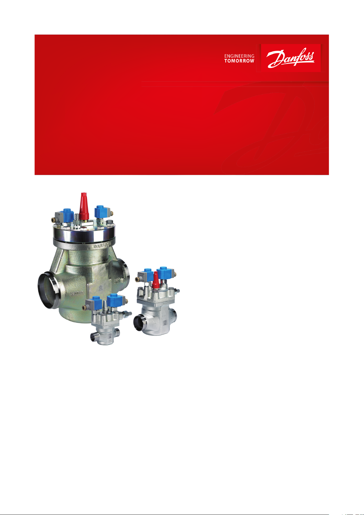
2-step solenoid valve
Type ICLX 32-150
Used in wet return and suction lines for the opening against
high dierential pressure
ICLX 2-step solenoid valves belong to the ICV
family.
ICLX are used in suction lines for the opening
against high dierential pressure, e.g. after hot
gas defrost in large industrial refrigeration
systems with ammonia, uorinated refrigerants
or CO2.
The ICLX valve is factory congured to open in
2 steps.
By following a simple procedure the valve can
be congured to open in 1 step only.
In 2-step conguration, step 1 opens to approx.
10% of the capacity after the pilot solenoid
valves are energized.
Step 2 opens automatically when the pressure
dierential across the valve has decreased to
approx. 1.25 bar / 18 psig.
The ICLX valve comprises ve main
components: Valve body, top cover, function
module and 2 pilot solenoid valves. On ICLX 32
– 150 the top cover and function module are
factoryassembled.
AI236186441601en-001001
Page 2

2-step solenoid valve, Type ICLX 32-150
Features
• Designed for Industrial Refrigeration applications for a maximum working pressure of 52 bar / 754 psig
• Applicable to HCFC, HFC, R717 (Ammonia) and R744 (CO2)
• Can be used in chemical and petro-chemical applications
• Direct welded connections
• Connection types include butt weld, socket weld and solder connections
• Low temperature steel body
• Low weight and compact design
• Only one signal required for both pilot solenoid valves
• The ICLX main valve top cover can be oriented in any direction without the function of pilot valves being aected
• Especially suitable for systems where low pressure drop is required
• Stabilizes working conditions and eliminates pressure pulsations during opening after defrosting
• Provides safety against pressure "shocks" as the valve can only open fully when Δp < 1.25 bar / 18 psig
• Cavitation resistant valve seat
• Manual opening possible
• PTFE seat provides excellent valve tightness
• Service friendly design
• Classication: DNV, CRN, BV, EAC etc. To get an updated list of certication on the products please contact your
local Danfoss Sales Company
© Danfoss | Climate Solutions | 2021.02 AI236186441601en-001001 | 2
Page 3
1
EVM NC
Danfoss
M27H0257_1
2
EVM NO
P2
P1
1
EVM NC
2
EVM NO
P2
P1
Danfoss
M27H0258_1
2-step solenoid valve, Type ICLX 32-150
Functions
Function
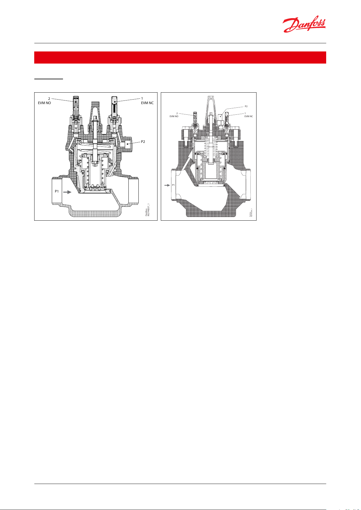
Figure 1: ICLX 32-65
Figure 2: ICLX 100-150
The ICLX valve is used as a shut-o valve in suction lines to open after hot gas defrost.
The valve is a pilot controlled valve operated by an external pilot pressure source. This means that the valve can
operate with no internal pressure dierential (Pd) at all.
Low Pd is the key objective and makes the ICLX valve ideal for applications that are sensitive to dierential pressure.
Though Pd is kept low, it can still be quantied, and must be considered when choosing valve size. See section -
Selection of ICLX valve - for the impact.
The main valve is provided with two pilot solenoid valves, as well as a nipple for connection to external pilot
pressure.
The external pilot pressure line must be connected to a system pressure (p2) which is at least 1.5 bar / 20 psi higher
than the inlet pressure (p1) of the valve. The dierence between the external pilot pressure and the inlet pressure of
the valve denes the maximum opening dierential pressure (MOPD) of the ICLX.
The ICLX is kept open when power is applied to the coils placed on the EVM pilot solenoid valves pos. 1 and pos. 2.
The ICLX is closing and kept closed when the coils on EVM pilot solenoid valves pos. 1 and pos. 2 are de-energised.
The pilot solenoid valve (pos.1) allows external pilot pressure (p2) to the bottom of the servo piston and thus opens
the rst step corresponding to approx. 10% of the valve capacity. At the same time the bleed spring will be
compressed. This will start a pressure equalization of the inlet pressure (p1) to the outlet pressure. When the
dierential pressure across the valve has fallen to approx. 1.25 bar / 18 psig the spring will be strong enough to
open the second step and open the valve for full capacity.
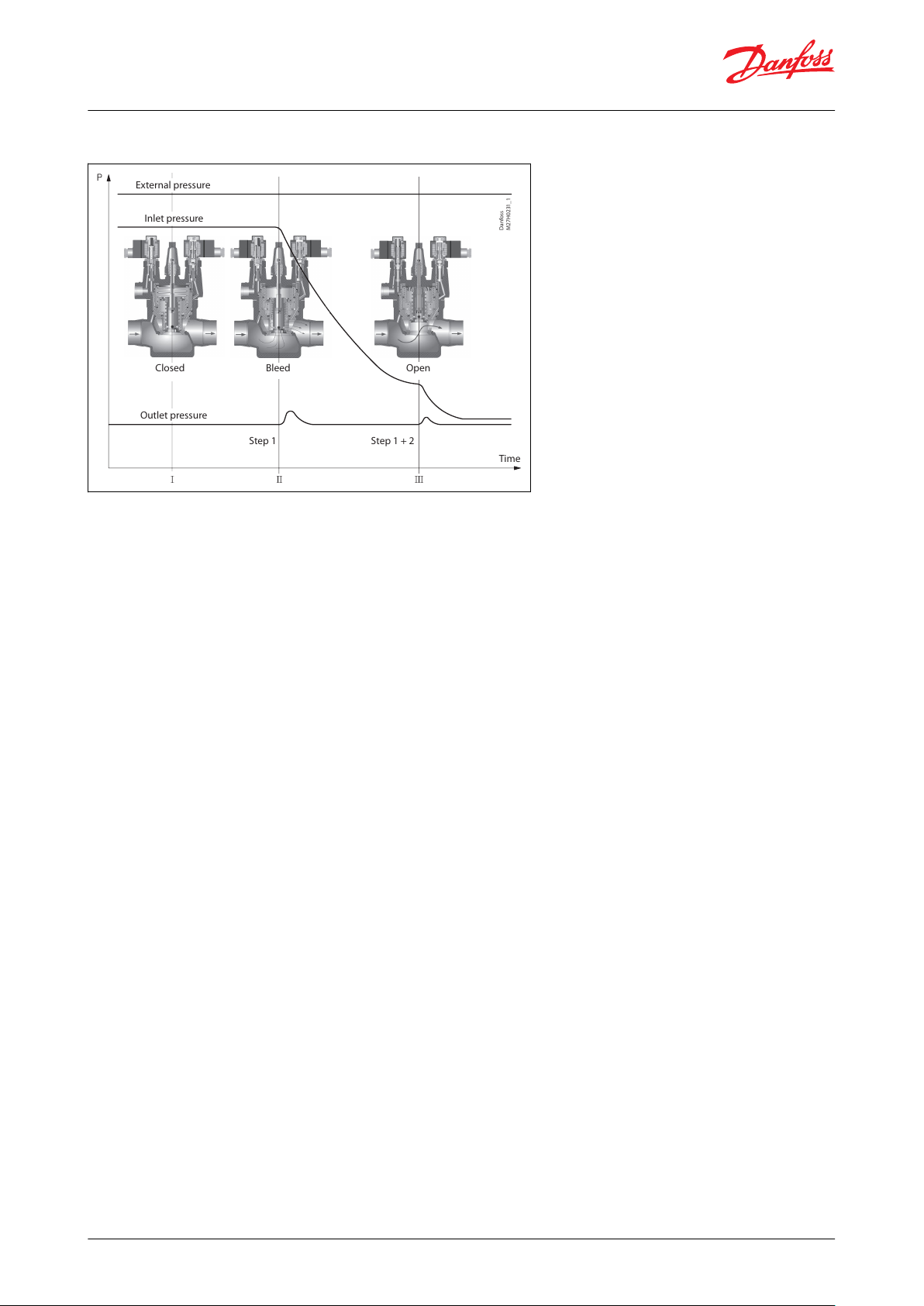
This way high-pressure pulsations, which would occur when opening for full capacity in one step, can be avoided.
ICLX must not be used in pipe systems where the dierential pressure across the main valve in open position can
exceed 1 bar / 15 psig, otherwise the step two on the valve will close.
© Danfoss | Climate Solutions | 2021.02 AI236186441601en-001001 | 3
Page 4
Danfoss
M27H0231_1
External pressure
Inlet pressure
Outlet pressure
Closed Bleed
Step 1 Step 1 + 2
Time
Open
2-step solenoid valve, Type ICLX 32-150
Figure 3: Two step opening principle
NOTE:
The ICLX valve is kept in its open position by hot gas. The hot gas condenses in the cold valve and creates liquid
under the servo piston. When the pilot valves change status to close the ICLX, the pressure on the servo piston
equalises with the suction pressure through the pilot valve (pos. 2). This equalisation takes time because condensed
liquid is present in the valve.
The exact time taken from when the pilot valves change position to complete closing of the ICLX will depend on
temperature, pressure, refrigerant and size of valve. Thus an exact closing time for the valves cannot be given but, in
general, lower temperatures give longer closing times.
It is very important to take the closing times into consideration when hot gas defrost is performed on evaporators.
Steps must be taken to ensure that the hot gas supply valve is not opened before the ICLX in the suction line is
completely closed. If the hot gas supply valve is opened before the ICLX in the suction line is closed, considerable
energy will be lost and potentially dangerous situations might arise because of “liquid hammer”. In ICLX valves, the
spring-loaded second stage might be induced to hammer by gas and liquid being forced through the valve at ∆p >
1.5 bar across the ICLX. The nal result could be severe damage to the valve.
As a rule of thumb a closing time of 2 minutes can be used as a starting point. The optimum closing time for each
individual system must be determined at initial start-up of the plant at intended operational conditions. It is
recommended to check if the closing time needs to be changed when conditions changes (suction pressure,
ambient temp. etc.) and closing time should be checked at service of the valve. Once the optimum closing time has
been identied it is recommended to add a safety margin of 30 sec. to the optimum closing time.
© Danfoss | Climate Solutions | 2021.02 AI236186441601en-001001 | 4
Page 5

2-step solenoid valve, Type ICLX 32-150
Media
Refrigerants
Applicable to HCFC, HFC, R717 (Ammonia) and R744 (CO2).
New refrigerants
Danfoss products are continually evaluated for use with new refrigerants depending on market requirements.
When a refrigerant is approved for use by Danfoss, it is added to the relevant portfolio, and the R number of the
refrigerant (e.g. R513A) will be added to the technical data of the code number. Therefore, products for specic
refrigerants are best checked at store.danfoss.com/en/, or by contacting your local Danfoss representative.
© Danfoss | Climate Solutions | 2021.02 AI236186441601en-001001 | 5
Page 6
Description
Values
Media temperature range
-60 °C / +120 °C / -76 °F / +248 °F
Max. working pressure
The valve is designed for a of 52 bar / 754 psig
Max. opening pressure dierential (MOPD):
21 bar / 305 psi @ external pressure 1.5 bar / 22 psi higher than inlet pressure of the valve
40 bar / 580 psi @ external pressure 2 bar (30 psi) higher than inlet pressure of the valve
Unit
ICLX 32
ICLX 40
ICLX 50
ICLX 65
ICLX 100
ICLX 125
ICLX 150
kv (m3/h)
22294782151
225
390
Cv (US
gal/min
)
25.5
33.6
54.595175
261
452
Description
Values
Surface protection
The ICLX external surface is zinc-chromated to provide good corrosion protection
Description
Values
Coil requirements:
Both coils to be IP67
EVM NC: 10W AC (or higher) for MOPD up to 21 bar
EVM NC: 20W AC for MOPD 21 – 40 bar
EVM NO: 10W AC (or higher)
ICV 32
ICV 40
ICV 50
ICV 65
2-step solenoid valve, Type ICLX 32-150
Product specication
Pressure and temperature
Table 1: Pressure and temperature data
Table 2: CV and KV values
Surface coating
Table 3: Surface coating
Coils
Table 4: Coils
The ICLX Concept
The ICLX concept is developed to highest exibility of direct welded connections. For valve sizes ICV 32 – ICV 65 a
wide range of connection sizes and types is available. ICV 100 – ICV 150 are available in butt-weld DIN and butt-weld
ANSI nominal sizes. The direct welded (non-anged) connections secures low risk of leakage.
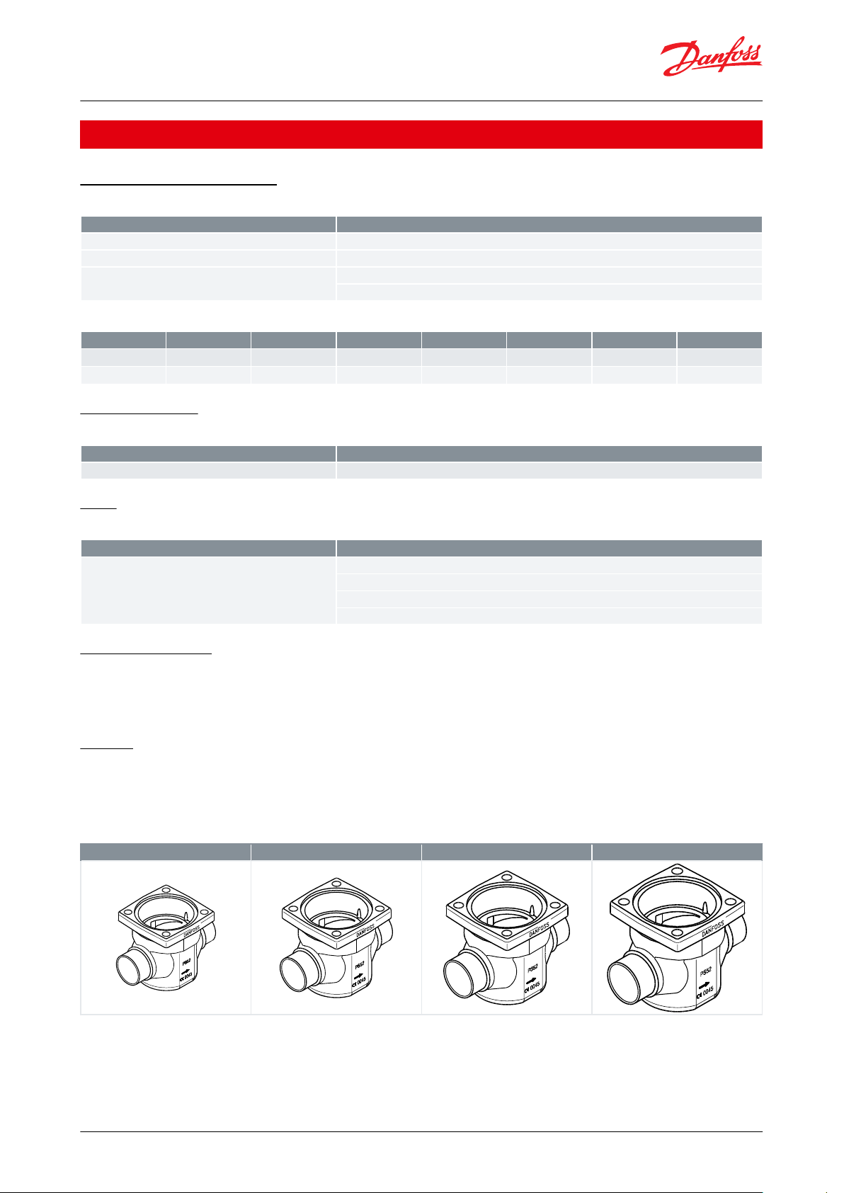
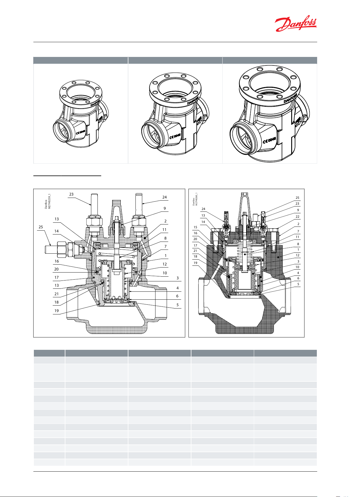
Design
Valve body and top cover material
Low temperature steel
There are seven valve bodies available
Table 5: ICV 32, 40, 50 and 65
© Danfoss | Climate Solutions | 2021.02 AI236186441601en-001001 | 6
Page 7
24
23
25
9
2
1
12
3
6
5
4
19
21
18
13
17
14
13
20
16
8
11
7
10
Danfoss
M27H0259_1
2
1
3
4
5
6
7
8
9
10
11
12
14
13
15
16
20
18
21
17
19
24
25
23
22
Danfoss
M27H0260_1
ICV 100
ICV 125
ICV 150
No.
Part
Material
EN
ASTM
1
Valve body
Low temperature steel
G20Mn5QT, EN 10213-3
LCC, A352
2
Top cover
ICLX 32-65: Low temperature steel
ICLX 100-150: Low temperature
steel
P285QH, EN 10222-4 P275NL2,
EN 10028
LF2, A350
3
Main piston
Steel
4
Bleed piston
Steel
5
Seat plate main
PTFE
6
Seat plate bleed
PTFE7Gasket
Fibre, non-asbestos
8
Spindle manual opener
Stainless steel
9
Packing gland
Steel10Insert
Steel
11
Spring - main
Stainless steel
12
Spring - bleed
Stainless steel
13
O-ring
Chloroprene (neoprene)
14
O-ring
Chloroprene (neoprene)
2-step solenoid valve, Type ICLX 32-150
Table 6: ICV 100, 125 and 150
Material specication
Figure 4: ICLX 32-65
Table 7: Material specication
Figure 5: ICLX 100-150
© Danfoss | Climate Solutions | 2021.02 AI236186441601en-001001 | 7
Page 8
No.
Part
Material
EN
ASTM
15
O-ring
ICLX 100-150 only, Chloroprene
(neoprene)
16
O-ring
Chloroprene (neoprene)
17
O-ring
Chloroprene (neoprene)
18
O-ring
Chloroprene (neoprene)
19
O-ring
Chloroprene (neoprene)
20
Seal
PTFE21Seal
PTFE22Bolt
Stainless steel
A2-70 EN 1515-1
A2-70, B1054
23
EVM pilot NC
24
EVM pilot NO
25
External pressure inlet
DASOCSDSA
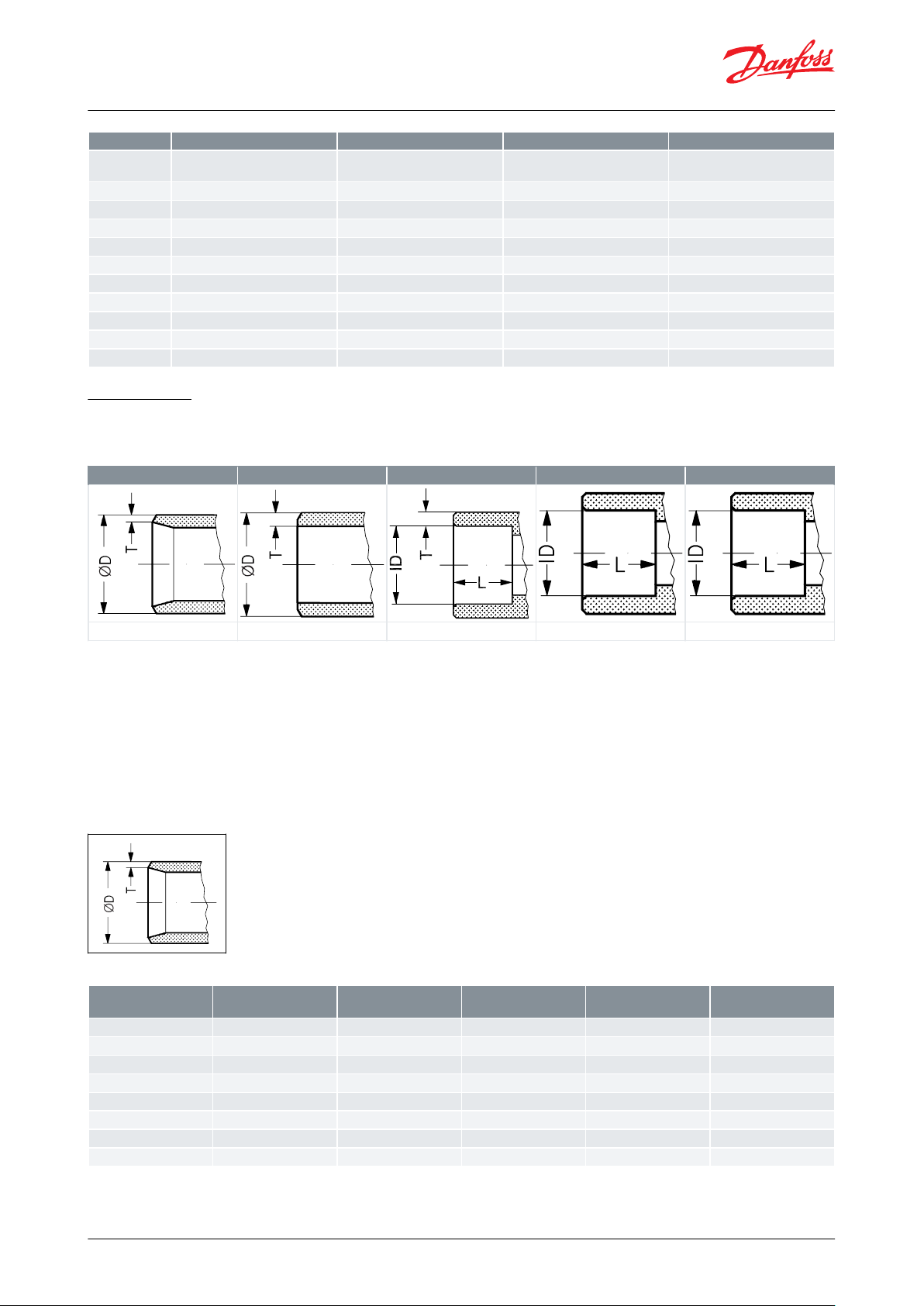
ø
Butt-weld DIN
Butt-weld ANSI
Socket weld ANSI
Solder DIN
Solder ANSI
ø
SizemmSize
in.ØDmmTmmØDin.Tin.
32
1
1
⁄4
42.4
2.6
1.669
0.102401
1
⁄2
48.3
2.6
1.902
0.103502
60.3
2.9
2.37
0.11652
1
⁄2
76.1
2.930.11803
88.9
3.2
3.5
0.13
100
4
114.3
3.6
4.5
0.14
125
5
140.745.5
0.16
150
6
168.3
6.3
6.6
0.25
2-step solenoid valve, Type ICLX 32-150
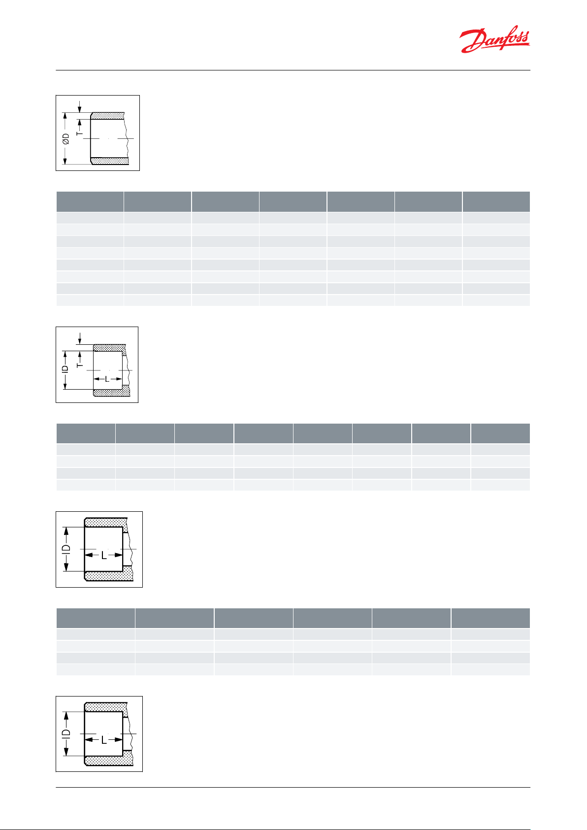
Connections
There is a wide range of connection types available with ICLX valves:
Table 8: Connections
• D: Butt weld, EN 10220
• A: Butt weld, ANSI (B 36.10)
• SOC: Socket weld, ANSI (B 16.11)
• SD: Solder connection, EN 1254-1
• SA: Solder connection, ANSI (B 16.22)
The ICLX valves are approved in accordance with the European standard specied in the Pressure Equipment
Directive and are CE marked.
Figure 6: D: Butt-weld (EN 10220)
Table 9: D: Butt-weld (EN 10220)
© Danfoss | Climate Solutions | 2021.02 AI236186441601en-001001 | 8
Page 9
SizemmSize
in.ØDmmTmmØDin.Tin.
Schedule
32
1
1
⁄4
42.4
4.9
1.669
0.193
80401
1
⁄2
48.3
5.1
1.902
0.201
80502
60.3
3.9
2.37
0.15
40652
1
⁄2
73
5.2
2.87
0.2
40803
88.9
5.5
3.5
0.22
40
100
4
114.364.5
0.24
125
5
140.7
6.5
5.5
0.26
150
6
168.3
7.1
6.6
0.28
SizemmSize
in.ØDmmTmmØDin.Tin.LmmLin.
32
1
1
⁄4
42.7
6.1
1.743
0.24130.51401
1
⁄2
48.8
6.6
1.921
0.26130.51502
61.2
6.2
2.41
0.24160.63652
1
⁄2
74
8.8
2.91
0.344160.63
SizemmSize
in.IDmmIDin.LmmLin.
35
35.07
254242.07
285454.09
337676.1
33
2-step solenoid valve, Type ICLX 32-150
Figure 7: A: Butt-weld ANSI (B 36.10)
Table 10: A: Butt-weld ANSI (B 36.10)
Figure 8: SOC: Socket welding ANSI (B 16.11)
Table 11: SOC: Socket welding ANSI (B 16.11)
Figure 9: SD: Soldering (EN 1254-1)
Table 12: SD: Soldering (EN 1254-1)
Figure 10: SA: Soldering (ANSI B 16.22)
© Danfoss | Climate Solutions | 2021.02 AI236186441601en-001001 | 9
Page 10
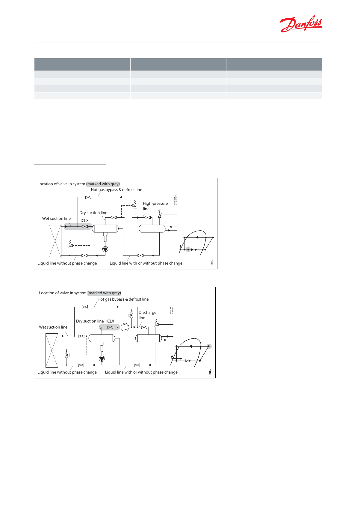
Location of valve in system (marked with grey)
Hot gas bypass & defrost line
Discharge
line
Wet suction line
Dry suction line
Liquid line without phase change Liquid line with or without phase change
ICLX
Size
in.IDin.Lin.
1
3
⁄8
1.375
0.984
1
5
⁄8
1.625
1.102
2
1
⁄8
2.125
1.3
2
1
⁄2
2.625
1.3
Hot gas bypass & defrost line
High-pressure
line
Wet suction line
Dry suction line
Liquid line without phase change Liquid line with or without phase change
ICLX
Location of valve in system (marked with grey)
2-step solenoid valve, Type ICLX 32-150
Table 13: SA: Soldering (ANSI B 16.22)
Valve selection based on capacity calculation
As for extended capacity calculations and valve selection based on capacities and refrigerants, please refer to
Coolselector®2. Rated and extended capacities are calculated with the Coolselector®2 calculation engine to ARI
standards with the ASEREP equations based on laboratory measurements of selected valves.
Download Coolselector®2 for free at coolselector.danfoss.com
Selection of ICLX valve
Figure 11: Wet suction line
Figure 12: Dry suction line
© Danfoss | Climate Solutions | 2021.02 AI236186441601en-001001 | 10
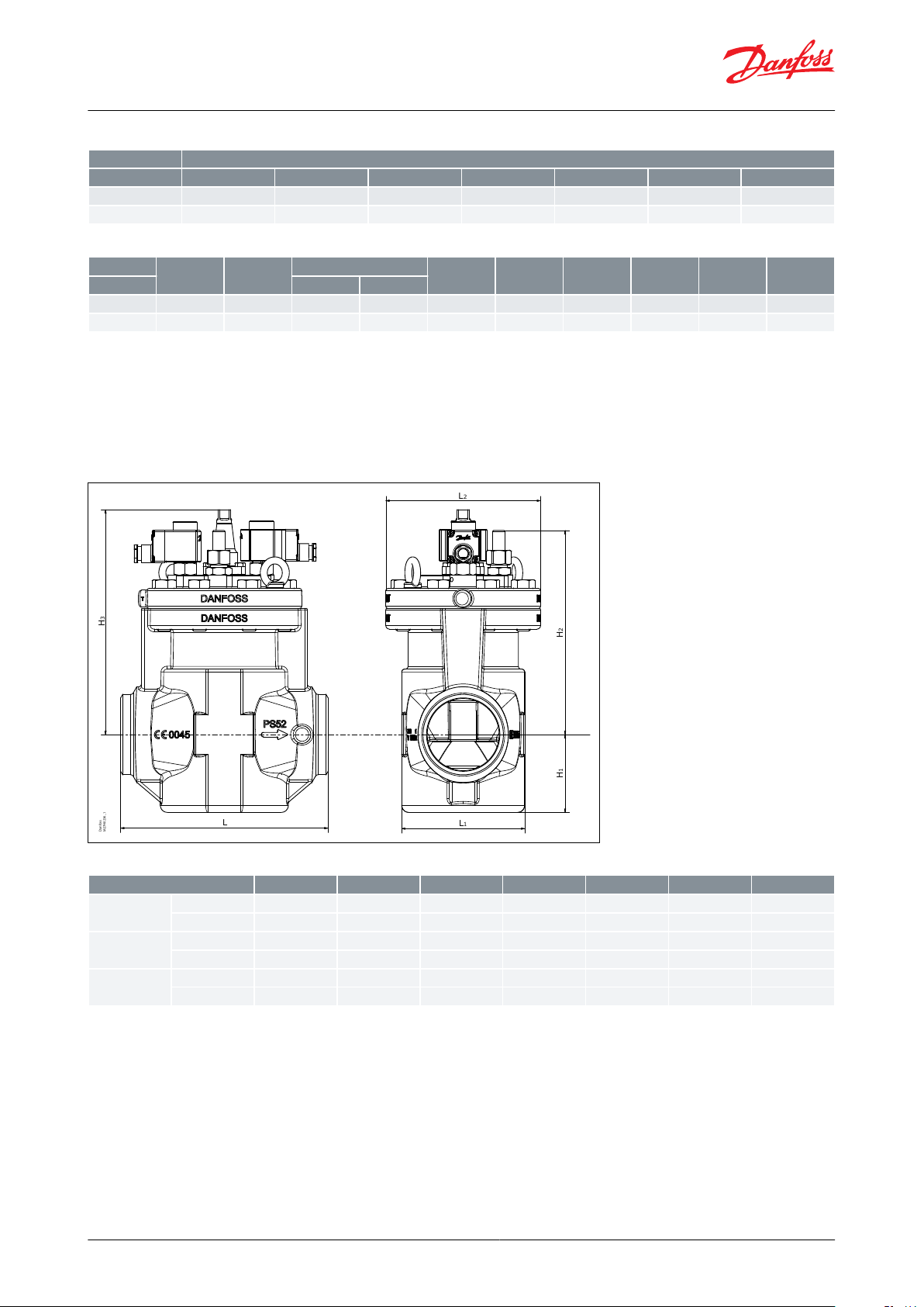
Page 11

L
3max
L4
H
4
H
3
L L1
L2
H
2
H
1
Danfoss
M27H0235_1
L
3max
TypeLICLX 32
32 D
40 D
32 A
40 A
32 SOC
35 SD
42 SD
42 SA
mm
145
145
145
145
148
148
148
148
in.
5.7
5.7
5.7
5.7
5.8
5.8
5.8
5.8
Type
L1L
2
L3max
L4H1H2H3H
4
Net weight
ICLX 32
10W
20W
mm
75
104
125
135
1594319382168
9.9 kg
in.
3
4.1
4.9
5.3
6.3
1.7
7.6
3.2
6.6
21.8 lb
TypeLICLX 40
40 D
50 D
40 A
50 A
40 SOC
42 SD
42 SA
mm
160
180
160
180
180
180
180
in.
6.3
7.1
6.3
7.1
7.1
7.1
7.1
Type
L1L
2
L3max
L4H1H2H3H
4
Net weight
ICLX 40
10W
20W
mm
86
109
125
135
1575221787174
11.7 kg
in.
3.4
4.3
4.9
5.3
6.228.5
3.4
6.9
25.8 lb
TypeLICLX 50
50 D
65 D
50 A
65 A
50 SOC
54 SD
mm
200
210
200
210
216
216
in.
7.9
8.3
7.9
8.3
8.5
8.5
Type
L1L
2
L3max
L4H1H2H3H
4
Net weight
ICLX 50
10W
20W
mm
100
126
125
135
15761240
102
217
15.3 kg
in.
3.954.9
5.3
6.2
2.4
9.448.5
33.7 lb
2-step solenoid valve, Type ICLX 32-150
Dimensions and weight
ICLX 32-65
Figure 13: ICLX 32-65
Table 14: ICLX 32
Table 15: ICLX 32
Table 16: ICLX 40
Table 17: ICLX 40
Table 18: ICLX 50
Table 19: ICLX 50
© Danfoss | Climate Solutions | 2021.02 AI236186441601en-001001 | 11
Page 12
TypeLICLX 65
65 D
80 D
65 A
80 A
65 SOC
76 SD
67 SA
mm
230
245
230
245
230
245
245
in.
9.1
9.6
9.1
9.6
9.1
9.6
9.6
Type
L1L
2
L3max
L4H1H2H3H
4
Net weight
ICLX 65
10W
20W
mm
130
141
125
135
16369257
123
234
20.3 kg
in.
5.1
5.6
4.9
5.3
6.4
2.7
10.1
4.8
9.2
44.7 lb
H
3
L
L1
L
2
H
2
H
1
Danfoss
M27H0236_1
Type
L
L1L2H1H2H
3
Net weight
ICLX 100
mm
295
175
220
111
297
320
53.2 kg
in.
11.6
6.9
8.7
4.4
11.7
12.6
117.3 lb
ICLX 125
mm
350
215
260
142
305
376
80.8 kg
in.
13.8
8.5
10.2
5.61214.8
178.1 lb
ICLX 150
mm
445
255
300
170
357
426
132.5 kg
in.
17.51011.8
6.7
14.1
16.8
292.1 lb
2-step solenoid valve, Type ICLX 32-150
Table 20: ICLX 65
Table 21: ICLX 65
D = Butt-weld DIN, A = Butt-weld ANSI, SOC = Socket weld ANSI, SD = Solder DIN, SA = Solder ANSI
NOTE:
Specied weights are approximate values only.
ICLX 100-150
Figure 14: ICLX 100-150
Table 22: ICLX 100-150
NOTE:
Specied weights are approximate values only.
© Danfoss | Climate Solutions | 2021.02 AI236186441601en-001001 | 12
Page 13
Valve body 40 D (1
1
⁄2 in.)
027H3125
Table 24
Top cover ICLX 32
027H3204
Table 25
32 D (1
1
⁄4 in.)
40 D (1
1
⁄2 in.)
42 SA (1
5
⁄8 in.)
42 SD (1
5
⁄8 in.)
027H3120
027H3125
027H3127
027H3128
35 SD (1
3
⁄8 in. SA)
32 A (1
1
⁄4 in.)
32 SOC (1
1
⁄4 in.)
40 A (1
1
⁄2 in.)
027H3123
027H3121
027H3122
027H3126
Description
Code Number
ICLX 32
027H3204
(1)
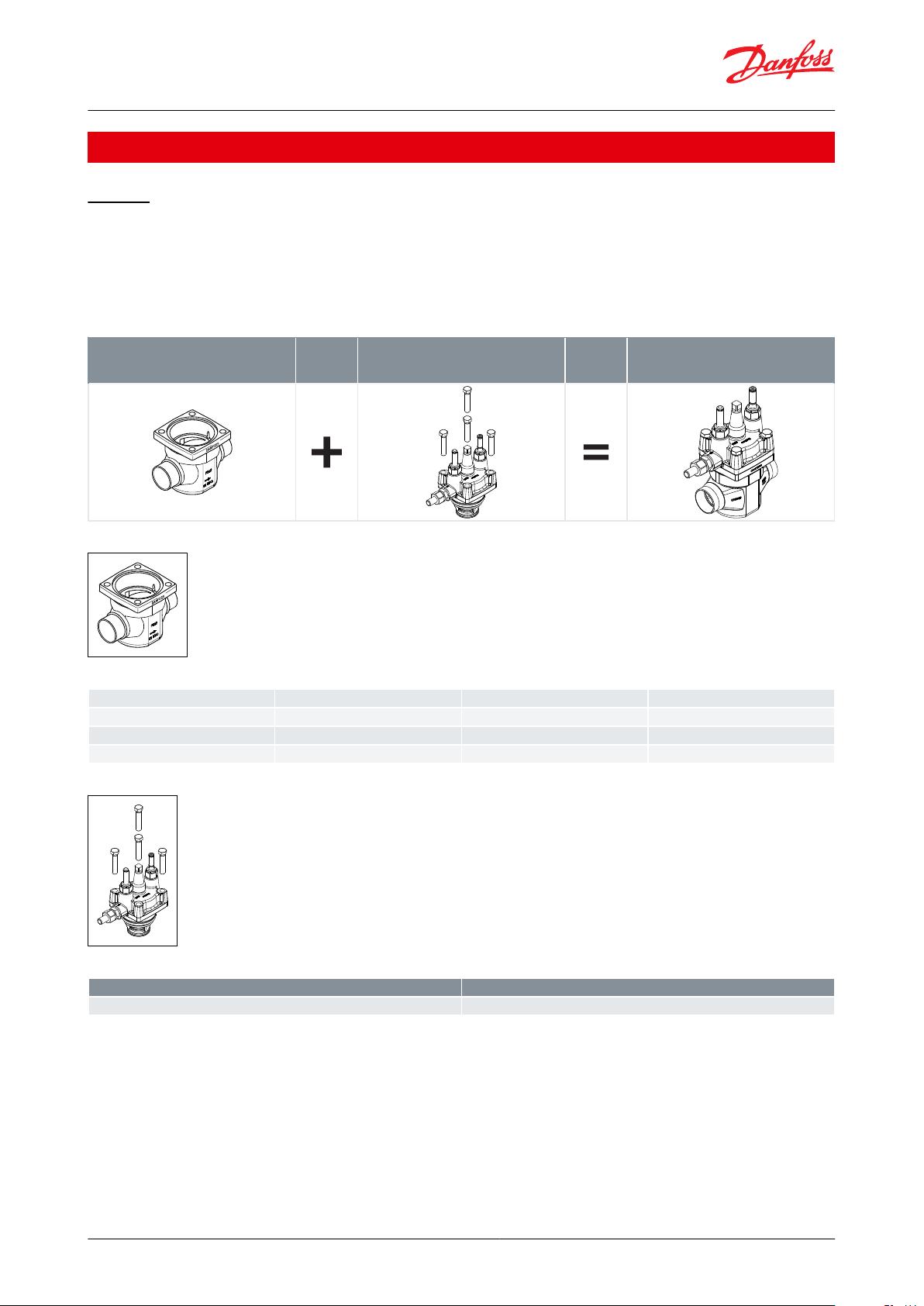
2-step solenoid valve, Type ICLX 32-150
Ordering
ICLX 32
Ordering from the parts programme
NOTE:
The ICLX function modules can only be used in housings produced in or after week 49 2012; thus the week code on
the housing must be 4912 or higher.
Table 23: Example (select from table 24 and 25)
Figure 15: ICV 32
Table 24: ICV 32 valve body w/dierent connections
Figure 16: ICLX 32
Table 25: ICLX 32 Function module / top cover
(1)
(1)
Including external pilot connection, NC/NO pilot valves, gasket and O-rings
Including external pilot connection, NC/NO pilot valves, gasket and O-rings
D = Butt-weld DIN
A = Butt-weld ANSI
SOC = Socket weld ANSI
SD = Solder DIN
SA = Solder ANSI
Ordering complete factory assembled valve
© Danfoss | Climate Solutions | 2021.02 AI236186441601en-001001 | 13
Page 14

Type ICLX 32
Available connections
32 D (1
1
⁄4 in.)
40 D (1
1
⁄2 in.)
42 SA (1
5
⁄8 in.)
42 SD (1
5
⁄8 in.)
35 SD (1
3
⁄8 in. SA)
32 A (1
1
⁄4 in.)
32 SOC (1
1
⁄4 in.)
40 A (1 ½ in.)
027H3040
(2)
(2)
(2)
(2)
027H3041
027H3042
(2)
Valve body A 40 (1
1
⁄2 in.)
027H4121
Table 28
Top cover ICLX 40
027H4204
Table 29
40 D (1
1
⁄2 in.)
50 D (2 in.)
42 SA (1
5
⁄8 in.)
42 SD (1
5
⁄8 in.)
027H4120
027H4126
027H4124
027H4123
40 A (1
1
⁄2 in.)
40 SOC (1
1
⁄2 in.)
50 A (2 in.)
027H4121
027H4122
027H4127
2-step solenoid valve, Type ICLX 32-150
Figure 17: ICLX 32
Table 26: (body, function module / top cover)
(2)
(2)
Select from parts programme
Select from parts programme
ICLX 40
Ordering from the parts programme
NOTE:
The ICLX function modules can only be used in housings produced in or after week 49 2012; thus the week code on
the housing must be 4912 or higher.
Table 27: Example (select from table 28 and 29)
Figure 18: ICV 40
Table 28: ICV 40 valve body w/dierent connections
Figure 19: ICLX 40
© Danfoss | Climate Solutions | 2021.02 AI236186441601en-001001 | 14
Page 15

Description
Code Number
ICLX 40
027H4204
(1)
Type ICLX 40
Available connections
40 D (1
1
⁄2 in.)
50 D (2 in.)
42 SA (1
5
⁄8 in.)
42 SD (1
5
⁄8 in.)
40 A (1
1
⁄2 in.)
40 SOC (1
1
⁄2 in.)
50 A (2 in.)
027H4040
(2)
(2)
(2)
027H4041
027H4042
(2)
Valve body 50 D (2 in.)
027H5120
Table 32
Top cover ICLX 50
027H5204
Table 33
2-step solenoid valve, Type ICLX 32-150
Table 29: ICLX 40 Function module / top cover
(1)
(1)
Including external pilot connection, NC / NO pilot valves, gasket and O-rings
Including external pilot connection, NC / NO pilot valves, gasket and O-rings
D = Butt-weld DIN
A = Butt-weld ANSI
SOC = Socket weld ANSI
SD = Solder DIN
SA = Solder ANSI
Ordering complete factory assembled valve
Figure 20: ICLX 40
Table 30: (body, function module / top cover)
(2)
(2)
Select from parts programme
Select from parts programme
ICLX 50
Ordering from the parts programme
NOTE:
The ICLX function modules can only be used in housings produced in or after week 49 2012; thus the week code on
the housing must be 4912 or higher.
Table 31: Example (select from table 32 and 33)
Figure 21: ICV 50
© Danfoss | Climate Solutions | 2021.02 AI236186441601en-001001 | 15
Page 16

50 D (2 in.)
65 D (2
1
⁄2 in.)
54 SD (2
1
⁄8 in. SA)
50 A (2 in.)
027H5120
027H5124
027H5123
027H5121
50 SOC (2 in.)
65 A (2
1
⁄2 in.)
50 A (2 in.)
027H5122
027H5125
Description
Code Number
ICLX 50
027H5204
(1)
Type ICLX 50
Available connections
50 D (2 in.)
65 D (2
1
⁄2 in.)
54 SD (2
1
⁄8 in. SA)
50 A (2 in.)
50 SOC (2 in.)
65 A (2
1
⁄2 in.)
027H5040
(2)
(2)
027H5041
027H5042
(2)
2-step solenoid valve, Type ICLX 32-150
Table 32: ICV 50 valve body w/dierent connections
Figure 22: ICLX 50
Table 33: ICLX 50 Function module / top cover
(1)
(1)
Including external pilot connection, NC/NO pilot valves, gasket and O-rings
Including external pilot connection, NC/NO pilot valves, gasket and O-rings
D = Butt-weld DIN
A = Butt-weld ANSI
SOC = Socket weld ANSI
SD = Solder DIN
SA = Solder ANSI
Ordering complete factory assembled valve
Figure 23: ICLX 50
Table 34: (body, function module / top cover)
(2)
(2)
Select from parts programme
Select from parts programme
ICLX 65
Ordering from the parts programme
NOTE:
The ICLX function modules can only be used in housings produced in or after week 49 2012; thus the week code on
the housing must be 4912 or higher.
© Danfoss | Climate Solutions | 2021.02 AI236186441601en-001001 | 16
Page 17

Valve body 65 SOC (2
1
⁄2 in.)
027H6123
Table 36
Top cover ICLX 65
027H6204
Table 37
65 D (2
1
⁄2 in.)
65 A (2
1
⁄2 in.)
80 D (3 in.)
80 A (3 in.)
027H6120
027H6121
027H6126
027H6127
67 SA (2
5
⁄8 in.)
76 SD (3 in.)
65 SOC (2
1
⁄2 in.)
027H6125
027H6124
027H6123
Description
Code Number
ICLX 65
027H6204
(1)
2-step solenoid valve, Type ICLX 32-150
Table 35: Example (select from table 36 and 37)
Figure 24: ICV 65
Table 36: ICV 65 valve body w/dierent connections
Figure 25: ICLX 65
Table 37: ICLX 65 Function module / top cover
(1)
(1)
Including external pilot connection, NC/NO pilot valves, gasket and O-rings
Including external pilot connection, NC/NO pilot valves, gasket and O-rings
D = Butt-weld DIN
A = Butt-weld ANSI
SOC = Socket weld ANSI
SD = Solder DIN
SA = Solder ANSI
Ordering complete factory assembled valve
Figure 26: ICLX 65
© Danfoss | Climate Solutions | 2021.02 AI236186441601en-001001 | 17
Page 18

Type ICLX 65
Available connections
65 D (2
1
⁄2 in.)
65 A (2
1
⁄2 in.)
80 D (3 in.)
80 A (3 in.)
67 SA (2
5
⁄8 in.)
76 SD (3 in.)
65 SOC (2
1
⁄2 in.)
027H6040
027H6041
027H8040
027H8042
(2)
(2)
027H6042
Type
Available connections
ICLX 100
100 D (4 in.)
100 A (4 in.)
027H7147
027H7148
Type
Available connections
ICLX 125
125 D (5 in.)
125 A (5 in.)
027H7157
027H7158
Type
Available connections
ICLX 150
150 D (6 in.)
150 A (6 in.)
027H7167
027H7168
2-step solenoid valve, Type ICLX 32-150
Table 38: (body, function module / top cover)
(2)
(2)
Select from parts programme
Select from parts programme
ICLX 100/125/150 Complete factory assembled valve
Body, function module /topcover and NC / NO pilot valves
Figure 27: ICLX 100 Figure 28: ICLX 125 Figure 29: ICLX 150
Table 39: ICLX 100
Table 40: ICLX 125
Table 41: ICLX 150
Spare parts and accessories
Figure 30: ICV PM anged valve housings
ICV PM anged valve housings
ICV PM anged valve housings can replace the PM valves on already installed refrigeration systems.
Pressure range
The ICV PM valve housing is designed for a max. working pressure of 28 bar g / 406 psig and therefore a suitable
replacement for PM valves in the service market. They also oer the same drop-in dimensions as the PM valves.
© Danfoss | Climate Solutions | 2021.02 AI236186441601en-001001 | 18
Page 19
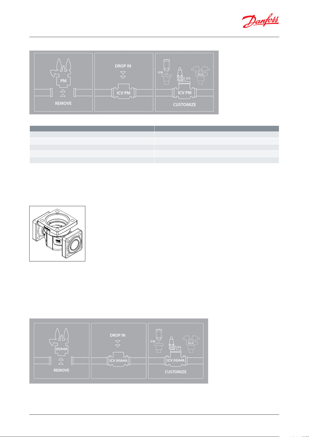
PM
REMOVE
ICV PM
ICV PM
DROP IN
ICM
ICS
ICLX
CUSTOMIZE
Description
Code no.
ICV 25 PM Valve housing
027H2119
(1)
ICV 32 PM Valve housing
027H3129
(1)
ICV 40 PM Valve housing
027H4128
(1)
ICV 50 PM Valve housing
027H5127
(2)
ICV 65 PM Valve housing
027H6128
(2)
(H)A4A
REMOVE
ICV (H)A4A
ICV (H)A4A
DROP IN
ICM
ICS
ICLX
CUSTOMIZE
2-step solenoid valve, Type ICLX 32-150
Figure 31: Assembly
Table 42: ICV PM anged valve housings
(1)
(1)
Includes ICV PM valve housing, ange gaskets and ange bolts.
Includes ICV PM valve housing, ange gaskets and ange bolts.
(2)
(2)
Includes ICV PM valve housing, ange gaskets, ange bolts and ange nuts.
Includes ICV PM valve housing, ange gaskets, ange bolts and ange nuts.
NOTE:
Function modules and top covers must be ordered separately (see the section Ordering).
Figure 32: ICV (H)A4A anged valve housings
ICV (H)A4A anged valve housings
ICV (H)A4A anged valve housings can replace the (H)A4A valves on already installed refrigeration systems.
Pressure range
The ICV (H)A4A valve housing is designed for a max. working pressure of 28 bar g / 406 psig and therefore a suitable
replacement for (H)A4A valves in the service market. They also oer the same drop-in dimensions as the (H)A4A
valves.
Figure 33: Assembly
© Danfoss | Climate Solutions | 2021.02 AI236186441601en-001001 | 19
Page 20
Description
Code no.
ICV 25 (H)A4A Valve housing
027H2304
(3)
ICV 32 A4A Valve housing
027H3130
(3)
ICV 32 HA4A Valve housing
027H3131
(3)
ICV 40 (H)A4A Valve housing
027H4129
(3)
ICV 50 (H)A4A Valve housing
027H5128
(4)
ICV 65 (H)A4A Valve housing
027H6129
(4)
Valve size
Code number
ICLX 32 – 40
148B3259
ICLX 50 – 100
148B4075
ICLX 125 – 150
148B4076
ICLX
Description
Code no.
32 – 80
External pilot connection (incl. damping
orice, D: 1.0 mm)
027F1048
32 – 80
External pilot connection (
1
⁄4" FPT) (incl. damping orice, D: 1.0 mm)
027B2065
100 – 150
External polot connection (incl. damping
orice, D: 1.8 mm)
027F1049
100 – 150
External pilot connection (
1
⁄4" FPT) (incl. damping orice, D: 1.8 mm)
027B2066
32 – 150
Accessory bag with seal and O-ring for pilot valve
027F0666
32 – 80
Damping
orice for EVM. 10 pcs, (D: 1.0 mm)
027F0664
100 – 150
Damping
orice for EVM. 10 pcs, (D: 1.8 mm)
027F0176
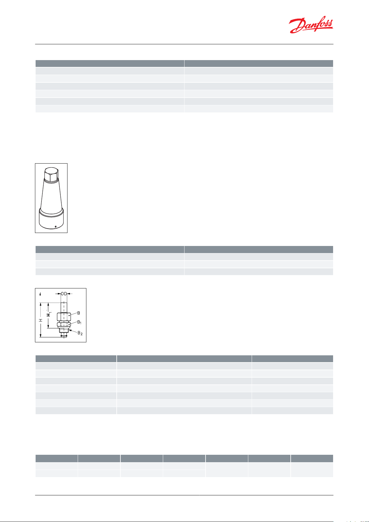
Size
H
H
1
øD
B
B1B
2
mm
906618
NV 32
NV 32
M 24 × 1.5
in.
3.54
2.6
0.71
2-step solenoid valve, Type ICLX 32-150
Table 43: ICV (H)A4A anged valve housings
(3)
(3)
Includes ICV (H)A4A valve housing, ange gaskets and ange bolts.
Includes ICV (H)A4A valve housing, ange gaskets and ange bolts.
(4)
(4)
Includes ICV (H)A4A valve housing, ange gaskets, ange bolts and ange nuts.
Includes ICV (H)A4A valve housing, ange gaskets, ange bolts and ange nuts.
NOTE:
Function modules and top covers must be ordered separately (see the section Ordering).
Figure 34: Cap including gasket
Table 44: Cap including gasket
Figure 35: External pilot connection
Table 45: External pilot connection
NOTE:
A damping orice should be installed if the pressure dierence between the low and the high pressure side is more
than 6 bar.
Table 46: Dimensions - see Fig. 35
© Danfoss | Climate Solutions | 2021.02 AI236186441601en-001001 | 20
Page 21
File name
Document type
Document topic
Approval authority
EAC RU Д-DK.БЛ08.B.03639
EAC Declaration
Machinery & Equipment
EAC
EAC RU Д-DK.БЛ08.B.00189_18
EAC Declaration
EMC
EAC
EAC RU Д-DK.РА01.B.71727_20
EAC Declaration
PED
EAC
EAC RU C-DK.БЛ08.B.01093_20
Pressure - Safety Certicate
PED
EAC
EU 033F0685.AK
EU Declaration
EMCD/PED
Danfoss
MD 033F0691.AE
Manufacturers Declaration
RoHS
Danfoss
TÜV 0045 202 1204 Z 00354 19 D 001(00)
Pressure - Safety Certicate
PED
TÜV
Manufacturers Declaration Danfoss 033F0474.AC
Manufacturers Declaration
ATEX
Danfoss
TSSA CRN.0C19205.2
Pressure - Safety Certicate
CRN
TSSA
RMRS 19.10325.266
Marine - Safety Certicate
RMRS
UL SA7200
Mechanical - Safety Certicate
UL
GMPI TSX71002520151140
Manufacturing Permission
GMPI
TSSA CRN.0C18990.5123467890YTN
Pressure - Safety Certicate
CRN
TSSA
ICLX valves
Nominal bore
DN≤ 25 (1 in.)
DN 32 – 65 (1 1/4 – 2 ½ in.)
DN 80 – 150 (3 – 6 in.)
Classied for
Fluid group I
Category
Article 3, paragraph 3
II
III
2-step solenoid valve, Type ICLX 32-150
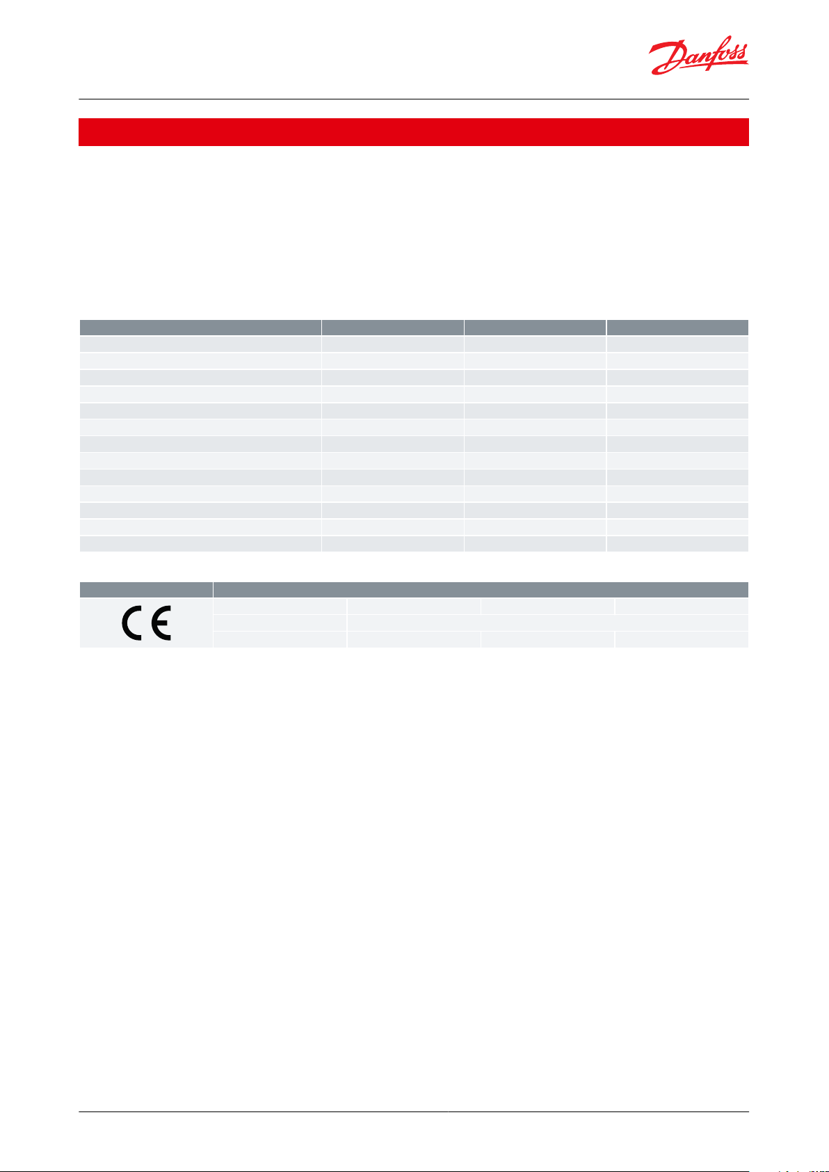
Certicates, declarations, and approvals
The list contains all certicates, declarations, and approvals for this product type. Individual code number may have
some or all of these approvals, and certain local approvals may not appear on the list.
Some approvals may change over time. You can check the most current status at danfoss.com or contact your local
Danfoss representative if you have any questions.
The ICV valve concept is designed to full global refrigeration requirements. The Factory assembled ICLX is CE and
UL approved. For specic approval information, please contact Danfoss.
Table 47: Valid approvals
Table 48: Compliance
© Danfoss | Climate Solutions | 2021.02 AI236186441601en-001001 | 21
Page 22
Online support
Danfoss oers a wide range of support along with our products, including digital product information, software,
mobile apps, and expert guidance. See the possibilities below.
The Danfoss Product Store
The Danfoss Product Store is your one-stop shop for everything product related—no matter where
you are in the world or what area of the cooling industry you work in. Get quick access to essential
information like product specs, code numbers, technical documentation, certications, accessories,
and more.
Start browsing at store.danfoss.com.
Find technical documentation
Find the technical documentation you need to get your project up and running. Get direct access to
our ocial collection of data sheets, certicates and declarations, manuals and guides, 3D models
and drawings, case stories, brochures, and much more.
Start searching now at www.danfoss.com/en/service-and-support/documentation.
Danfoss Learning
Danfoss Learning is a free online learning platform. It features courses and materials specically
designed to help engineers, installers, service technicians, and wholesalers better understand the
products, applications, industry topics, and trends that will help you do your job better.
Create your Danfoss Learning account for free at www.danfoss.com/en/service-and-support/learning.
Get local information and support
Local Danfoss websites are the main sources for help and information about our company and
products. Find product availability, get the latest regional news, or connect with a nearby expert—all
in your own language.
Find your local Danfoss website here: www.danfoss.com/en/choose-region.
Spare Parts
Get access to the Danfoss spare parts and service kit catalog right from your smartphone. The app
contains a wide range of components for air conditioning and refrigeration applications, such as
valves, strainers, pressure switches, and sensors.
Download the Spare Parts app for free at www.danfoss.com/en/service-and-support/downloads.
Coolselector®2 - nd the best components for you HVAC/R system
Coolselector®2 makes it easy for engineers, consultants, and designers to nd and order the best
components for refrigeration and air conditioning systems. Run calculations based on your operating
conditions and then choose the best setup for your system design.
Download Coolselector®2 for free at coolselector.danfoss.com.
Danfoss can accept no responsibility for possible errors in catalogues, brochures and other printed material. Danfoss reserves the right to alter its
products without notice. This also applies to products already on order provided that such alterations can be made without subsequential
changes being necessary in specications already agreed. All trademarks in this material are property of the respective companies. Danfoss and
the Danfoss logotype are trademarks of Danfoss A/S. All rights reserved.
© Danfoss | Climate Solutions | 2021.02 AI236186441601en-001001 | 22
 Loading...