

Page 1
Installation Guide
EVM NO
EVM NO
2-step solenoid valve
ICLX 100-150
Installation | Montage | Instalación | Instalação | 安装 | Montaż zaworu | Монтаж
ICLX 100
027R9902
ICLX 125
EVM NO
EVM (NA)
EVM NA
EVM NO
EVM NO
EVM (NA)
EVM NA
EVM NO
EVM (NA)
EVM NA
1a 1b
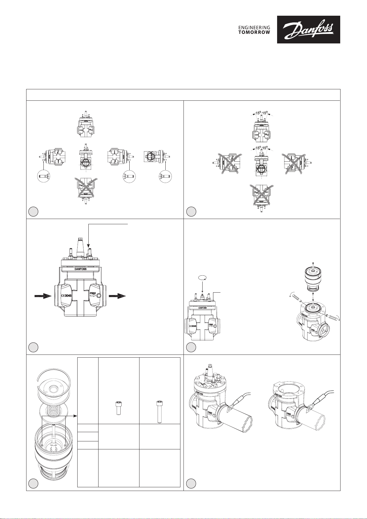
External pressure inlet
Entrée de pression externe
Entrada de presión externa
EVM NO
EVM (NA)
EVM NA
EVM NC
EVM (NC)
EVM NF
Entrada de pressão externa
外部压力入口
Wlot ciśnienia sterującego
Внешняя пилотная линия
ICLX 150
Remove spindle sign, lock ring and lock washer.
Retirez la marque de la tige, l’anneau de blocage et la rondelle frein.
Retirar la cubierta del eje, el anillo de bloqueo y la arandela de bloqueo.
Remova o sinal do eixo, anel de bloqueio e arruela de bloqueio.
取下旋杆标签、锁环和锁紧垫圈。
Zdemontować znacznik wrzeciona, pierścień blokujący i podkładkę.
Снимите со штока стопорное кольцо и стопорную шайбу.
Unscrew and remove all top cover bolts
Vissez la tige vers le bas, jusqu’en n de letage.
Girar el eje presionando hacia abajo para extraerlo.
Gire o eixo para baixo
向下转动旋杆,使
Wykręcić wrzeciono z gwintu w dół.
Выверните шток с резьбы вниз
para fora da rosca.
之与螺纹脱开。
027R9902
Turn spindle downwards out of thread.
Dévissez et retirez tous les boulons du
couvercle supérieur.
Desenroscar y retirar todos los pernos de
la tapa superior.
Solte o parafuso e remova todos os
parafusos da tampa.
Flow direction
Direction du ux
Sentido de ujo
Direção do uxo
流向
Kierunek przepływu
2
Направление потока
ICLX 100
ICLX 125
ICLX 150
two-step
deux temps
Dos etapas
dois estágios
两步式
Praca
dwustopniowa
двухступенчатый
M6 x 6 M6 x 16
Allen key
Clé Allen
Llave Allen
Chave Allen
内六角
Klucz imbusowy
Торцевой ключ
one-step
un temps
Una etapa
um estágio
一步式
Praca
jednostopniowa
одноступенчатый
Allen key
Clé Allen
Llave Allen
Chave Allen
内六角
Klucz imbusowy
Торцевой ключ
3
Only for heat controlled welding with no welding debris.
Uniquement pour les soudages à chaleur contrôlée sans résidus.
Sólo para soldadura con control de calor y sin residuos de soldadura.
Somente para soldagem com aquecimento controlado sem detritos da soldagem.
只可采用不产生焊屑的控温焊接。
Przeznaczone wyłącznie do spawania z kontrolą temperatury i bez odprysków.
Только при сварке схорошим отводом тепла.
54
拧下顶盖上的所有螺栓
Odkręcić i wyjąć wszystkie śruby górnej
pokrywy.
Отверните и снимите все крепежные
болты с верхней крышки.
© Danfoss | DCS (MWA) | 2016.12
DKRCI.PI.HS1.B4.ML | 520H6627 | 1
Page 2

BB A
B
Valve body size
Taille du corps de vanne
Tamaño del cuerpo de la válvula
Corpo da válvula tamanho
阀体 尺寸
Wielkość zaworu
Размер корпуса клапана
Pos. A
位置 A
Pos. B
位置 B
100
150
100
150
6
Nm ft lb
220 162125
50 37125
A
Normal operation mode
Mode de fonctionnement normal
Modo de funcionamiento normal
Modo de operação normal
Tryb normalnej pracy wrzeciono wkręcone
正常工作模式
Штатный режим
A
Clockwise
Sens des aiguilles
En el sentido
Sentido horário
顺时针方向
Zgodnie z ruchem
По часовой стрелке
Counter clockwise
Sens inverse des aiguilles d’une montre
En sentido contrario a las agujas del reloj
Sentido anti-horário
逆时针方向
Przeciwnie do ruchu
Против часовой стрелки
d’une montre
de las agujas
wskazówek
wskazówek
del reloj
zegara
zegara
7
© Danfoss | DCS (MWA) | 2016.12
Manual forced opening
Ouverture manuelle forcée
Apertura manual forzada
Abertura manual forçada
Wymuszone otwarcie wrzeciono wykręcone
Принудительное ручное открытие
手动强制开通
DKRCI.PI.HS1.B4.ML | 520H6627 | 2
Page 3
1. Body
Corps
Cuerpo
Corpo
阀体
Korpus zaworu
Корпус клапана
2. Top cover
Couvercle supérieur
Tapa superior
Tampa
顶盖
Pokrywa górna
Верхняя крышка
3. Function module
Module de fonction
Módulo de función
Módulo de função
功能模块
Moduł roboczy
Функциональный модуль
4. Gasket
Joint d’étanchéité
Junta
Gaxeta
垫片
Uszczelka
Прокладка
5. Bolts
Boulons
Pernos
Parafusos
螺栓
Śruby
Болты
6. EVM NO
EVM NO
EVM (NA)
EVM NA
EVM NO
EVM NO
EVM NO
7. Manual operating spindle
Tige de fonctionnement manuel
Eje de accionamiento manual
Eixo de operação manual
手动操作旋杆
Wrzeciono ręcz. otwierania
Шток ручного управления
8. EVM NC
EVM NC
EVM (NC)
EVM NF
EVM NC
EVM NC
EVM NC
9. External pressure inlet
Entrée de pression externe
Entrada de presión externa
Entrada de pressão externa
外部压力入口
Wlot ciśnienia sterującego
Патрубок внешней пилотной линий
10. Cap
Capuchon
Tapón
Tampa
阀帽
Kołpak
Колпачок
11. Eyebolt threads
Filetages des boulons à œil
Oricios roscados para argollas
Olhal com rosca
吊环螺栓
Gwinty do śrub oczkowych
Резьба рым-болта
8
9
11
11
11
1. Manual operating spindle
Tige de fonctionnement manuel
Eje de accionamiento manual
Eixo de operação manual
手动开启旋杆
Wrzeciono ręcz. otw.
Шток ручного управления
2. Insert
Insert
Funda
Inserto
插入件
10
Korpus mod. roboczego
Функциональный модуль
3. Piston assembly
Ensemble piston
Conjunto del pistón
Conjunto do pistão
活塞组件
Zespół tłoka
6
Поршень в сборе
4. Spring retainer (lower)
Cale du ressort (inférieure)
Retén del muelle (inferior)
Retentor da mola (inferior)
弹簧承座(下部)
Element ustalający sprężyny (dolny)
Стопор пружины (нижний)
5. Spring
Ressort
5
Muelle
Mola
弹簧
Sprężyna
Пружина
6. Spring retainer (upper)
Cale du ressort (supérieure)
Retén del muelle (superior)
Retentor da mola (superior)
弹簧承座(上部)
Element ustalający sprężyny (górny)
2
Стопор пружины (верхний)
7. Retaining ring
Anneau de retenue
Anillo de retención
4
Anel de retenção
扣环
Pierścień blokujący
7
Стопорное кольцо
1. Sealing retainer
Joint de retenue
Retén de sellado
3
Retentor de vedação
密封承座
Element ustalający uszczelnień
Фиксирующее уплотнение
2. PTFE seat plate main
Plaque de siège PTFE – principal
Placa de asiento de PTFE, principal
Placa da válvula PTFE
PTFE 主座板
Uszcz. 2 stopień (PTFE)
Основная тефлоновая клапанная пластина
3. Main piston
1
Piston principal
Pistón principal
Pistão principal
主活塞
Tłok główny
Основной поршень
4. Sealing retainer
Joint de retenue
Retén de sellado
Retentor de vedação
密封承座
Element ustalający uszczelnienia
Фиксирующее уплотнение
5. PTFE seat plate bleed
Plaque de siège PTFE – vidange
Placa de asiento de PTFE, purga
Purga da placa PTFE
PTFE 泄流阀板
Uszcz. 1 stopień (PTFE)
Спускная тефлоновая клапанная пластина
6. Bleed piston
Piston – vidange
Pistón de purga
Pistão de purga
泄流活塞
Tłok pomocniczy
Спускной поршень
7. Bleed spring
Ressort – vidange
Muelle de purga
Mola de purga
泄流弹簧
Sprężyna pomocnicza
Спускная пружина
8. Main piston top
Plaque supérieur piston
Pistón principal, pieza superior
Topo do pistão principal
主活塞顶部
Pokrywa głównego tłoka
Крышка основного поршня
9. Bolts
Boulons
Pernos
Parafusos
螺栓
Śruby
8a 8c
Болты
Uwaga - Gniazdo uszczelki 2 stopnia
Внимание -
7
6
5
4
3
2
1
Caution - Seal seat
Attention - joint du siège
Precaución: Asiento del sello
Cuidado -
Assento de vedação
注意 - 密封阀座
Седловое уплотнение
8b
9
8
7
6
5
4
3
2
1
Caution - Seal seat
Attention - joint du siège
Precaución: Asiento del sello
Cuidado -
Assento de vedação
Uwaga - Gniazdo uszczelki 2 stopnia
Внимание -
注意 - 密封阀座
Седловое уплотнение
© Danfoss | DCS (MWA) | 2016.12
DKRCI.PI.HS1.B4.ML | 520H6627 | 3
Page 4
1
3
4
2
3
4
3
5
6
2
1
Valve size
Taille de la vanne
Tamaño de la válvula
Tamanho da válvula
阀门规格
Valve size
Размер клапана Nm lb-ft
100-150 100 74
Valve size
Taille de la vanne
Tamaño de la válvula
Tamanho da válvula
阀门规格
Valve size
Размер клапана Nm lb-ft
100-150 100 74
2
1
Valve size
Taille de la vanne
Tamaño de la válvula
Tamanho da válvula
阀门规格
Valve size
Размер клапана Nm lb-ft
100 100 74
125 150 111
150 260 192
9a 9b
ENGLISH
Installation
Refrigerants
Applicable to all common non-ammable
refrigerants, including R717 and R744 (CO2)
and all non-corrosive gases/liquids.
Flammable hydrocarbons are not
recommended.
The valve is only recommended for use in
closed circuits. For further information please
contact Danfoss.
Temperature range
–60/+120°C (–76/+248°F)
Pressure
The valves are designed for a max.
working pressure of 52 bar g (754 psi g).
Application
The ICLX is used in suction lines for the
opening against high dierential pressure,
e.g. after hot gas defrost in large industrial
refrigeration systems with ammonia,
ourinated refrigerants or CO2.
The ICLX opens in two steps:
Step one opens to approx. 10% of the
capacity, when the pilot solenoid valves are
activated.
Step two opens automatically after the
pressure dierential across the valve reaches
approximately 1 bar.
External pressure
The external pressure applied to the ICLX
should always be 1.5 bar higher than the inlet
pressure of the valve. This will give the valve
a MOPD of 28 bar. If the external pressure is 2
bar higher than the inlet pressure the MOPD
of the ICLX will be 40 bar.
Electrical wiring
The ICLX valve is a normally closed design.
To ensure that the valve operates as normally
closed it is important that the EVM NC pilot
is mounted in the pilot port marked NC in
the top cover, EVM NO in port NO and the
external pressure to E (g. 2). For normal
operation mode both pilots should be
energized simultaneously, e.g. same signal
can be used for both pilots.
Coil requirements
Both coils must be IP67.
EVM NC: 10W ac (or higher) for MOPD
up to 21 bar
EVM NC: 20W ac for MOPD 21 → 40 bar
EVM NO: 10W ac (or higher)
The valve will have a malfunction
in systems where the pressure
dierential across the valve in normal
open conditions will exceed 1 bar (15
psig). In this case the step two of the
valve will close.
The valve/valve housing can be lifted by
means of eyebolts positioned like shown in
g. 8a, pos. 11.
Orientation
The valve must be installed with the arrow in
the direction of the ow (g. 2).
The top cover can be rotated 4x90° in relation
to the valve body.
ICLX 150
The valve must be installed with the spindle
in upwards position 15°/15° (g. 1b).
ICLX 100 and 125
The valve must be installed with the pilots
pointing in one of the directions shown in g.
1a. Downwards pointing pilots (any angle) is
not possible.
If the ICLX is installed with a vertical pilot
orientation (see g. 1a) attention should be
paid to have the EVM NO in lower position. If
needed rotate the top cover.
The valve is tted with a spindle for manual
opening. Make sure that the external pilot
line is connected to the upper side of the
main line so that any dirt and oil from the
plant will not nd its way into the pilot line.
The valve is designed to withstand a high
internal pressure. However, the piping system
should be designed to avoid liquid traps and
reduce the risk of hydraulic pressure caused
by thermal expansion. It must be ensured
that the valve is protected from pressure
transients like “liquid hammer” in the system.
9c
Welding (g. 5 and 8a)
For heat controlled welding methods and
welding methods ensuring no debris, the
valve can stay assembled during the welding
process.
The top cover (g. 8a, pos. 2) and function
module (g. 8a, pos. 3), can be removed
before welding to prevent damage to o-rings
and teon (PTFE) in the function module.
The function module can be lifted out by
applying a vertical force on the grooves as
shown in gure 3. Additionally eyebolts can
be threaded as shown in g. 8a, pos. 11 for
external lifting.
The internal surfaces and weld
connections of the enclosed ICLX
valve have been applied with
an anti-corrosion treatment.
In order to maintain the eectiveness
of this anti-corrosion treatment, it is
important to ensure that the valve is
disassembled just prior to the welding /
brazing process being undertaken.
In the event that the function modules are
to be left disassembled for even a short
period, please ensure that the function
modules are further protected by placing
in a polyethylene bag or by applying a rust
protection agent (e.g. refrigeration oil or
BRANOROL) on the surfaces.
Only materials and welding methods,
compatible with the valve body material,
must be applied to the valve body.
Avoid welding debris and dirt in the
valve body and the function module. The
valve body must be free from stresses
(external loads) after installation.
The valves must not be mounted in systems
where the outlet side of the valve is open
to atmosphere. The outlet side of the valve
must always be connected to the system
or properly capped o, for example with a
welded-on end plate.
© Danfoss | DCS (MWA) | 2016.12
DKRCI.PI.HS1.B4.ML | 520H6627 | 4
Page 5
ENGLISH
Assembly
Remove welding debris and any dirt from
pipes and valve body before assembly.
Check that the o-rings are intact before
replacing the function module. If possible,
apply some refrigeration oil to ease the
insertion and to protect the o-rings. Check
that the top gasket has not been damaged. If
the surface has been damaged or the gasket
has been bent, it must be replaced.
Tightening (g. 6)
Tighten the top cover with a torque wrench,
to the values indicated in the table.
Colours and identication
The ICLX valves are Zinc-Chromated from
factory. The Zinc-Chromatization does not
cover the welding connections. If further
corrosion protection is required, the valves
can be painted.
The external surface of the valve housing
must be protected against corrosion with
a suitable top coating after installation
involving welding and consequent assembly.
Protection of the ID plate when painting the
valve is recommended.
Important note for ICLX valves:
The ICLX valve is kept in its open
position by hot gas. The hot gas
condenses in the cold valve and
creates liquid under the servo piston.
When the pilot valves change status to close
the ICLX, the pressure on the servo piston
equalises with the suction pressure through
the pilot valve.
This equalisation takes time because
condensed liquid is present in the valve.
The exact time taken from when the pilot
valves change position to complete closing
of the ICLX will depend on temperature,
pressure, refrigerant and size of valve. Thus
an exact closing time for the valves cannot
be given but, in general, lower temperatures
give longer closing times.
It is very important to take the closing times
into consideration when hot gas defrost is
performed on evaporators.
Steps must be taken to ensure that the
hot gas supply valve is not opened before
the ICLX in the suction line is completely
closed. If the hot gas supply valve is opened
before the ICLX in the suction line is closed,
considerable energy will be lost and
potentially dangerous situations might arise
because of “liquid hammer”. In ICLX valves,
the spring-loaded second stage might be
induced to hammer by gas and liquid being
forced through the valve at Δp > 1.5 bar
across the ICLX. The nal result could be
severe damage to the valve.
As a rule of thumb a closing time of 2
minutes can be used as a starting point.
The optimum closing time for each
individual system must be determined
at initial start-up of the plant at intended
operational conditions. It is recommended
to check if the closing time needs to be
changed when conditions changes (suction
pressure, ambient temp. etc.) and closing
time should be checked at service of the
valve.
Once the optimum closing time has been
identied it is recommended to add a safety
margin of 30 sec. to the optimum closing
time.
Maintenance
Service
The ICLX valves can be disassembled for
service purposes.
Only skilled and trained refrigeration
engineers are allowed to service the ICLX
valves.
Do not open the valve while the valve is still
under pressure.
Pressure relief can be done by carefully
opening the manual operating spindle.
Small grooves along the thread will release
refrigerant into open air. This operation must
only be done after providing the correct
countermeasures under local legislation.
The function module can be lifted out by
applying a vertical force on the grooves
shown in gure 3.
Upon opening and removal of the function
module:
- Check that the o-rings on the function
module has not been damaged.
A valve with a damaged o-ring might not
operate according to the specication.
- The insert and piston assembly can be
disassembled according to gure 8b & 8c.
Be careful when removing the retaining
ring (g. 8b, pos. 7). The retaining ring (g.
8b, pos. 7) will be submitted to the force
from the compressed spring (g 8b, pos. 5).
Be careful not to damage the two
Seal Seats shown in g. 8b and 8c
since any deformation of the steel
surface will lead to malfunction of
the valve
- Check pistons, cylinders and valve plates
for wear and scratches and replace if
needed.
- Check that the movement of the pistons
and valve seats are free and with low
friction.
Replacement of Valve Plates
(ordinary wear parts)
It is possible to replace the two PTFE valve
plates (g. 8c, pos. 2 and pos. 5) by following
g. 9 and these instructions:
Fig. 9a, pos.1 shows a tool (purpose made)
that ts into the hole pattern of the sealing
retainer (pos. 3) of the piston assembly.
As backstop when unscrewing the sealing
retainer it is recommended to make an
arrangement of two steel pins that ts into
the female hexagon holes of the Allen bolts
(g. 8c, pos. 9), clamped into a vice (g. 9a,
pos. 2).
Once the sealing retainer is removed, the
Valve plate (pos. 4) can be lifted out.
Move the two steel pins (g. 9b, pos.2) to a
higher position in the vice to allow the bleed
piston (g. 9b, pos. 3) to be slided downwards
and expose two elongated holes (pos.4).
While there is access to the holes (pos. 4) a
steel bar (pos.5) with matching dimensions
is inserted through the two opposed holes
with tool pos. 1 (or similar fork tool) bridging
the bar.
Unscrew the main piston (g. 9b, pos. 6).
For disassembling of the last sealing retainer
it is recommended to utilise a mandrel with
three point suspension to avoid deformation
of the surfaces (g. 9c).
Clamp the bleed piston carefully to the
mandrel at surface pos.1. Block the mandrel
from rotation and unscrew the sealing
retainer with a tool (pos.2) manufactured for
the purpose.
When the sealing retainer is removed
the remaining valve plate (pos. 3) can be
replaced.
Reassembling of the piston assembly is done
in reverse order. The torque values for the
dierent joints are shown in g. 9.
Assembly
Remove any dirt from the body before the
valve is assembled. Check that all channels
in the valve are not blocked by particles or
similar.
If possible, apply some refrigeration oil to ease
the insertion and to protect the o-rings.
Tightening (g. 6)
Tighten the top cover with a torque wrench, to
the values indicated in the table.
Changing from two step to
one step function
The ICLX valve is from factory side setup as
two step function. To change the opening
characteristics to one step function the
following step must be completed:
- Remove the function module from the
valves house (g 3.).
- Remove the locking ring, upper spring
retainer, spring and lower spring retainer
(g. 4).
- Change the two bolts (g 8c, pos. 9).
- The length of the two bolts corresponds
to the desired characteristic of the valve
and should be applied according to the
table (g. 4).
- After changing the bolts the valve can be
reassembled.
Manual opening device (g. 7)
Normal operation mode
For the valve to operate normally under the
inuence of the pilot valves the spindle of the
manual operation device needs to be turned
fully clockwise until the locking ring (A) sits
on the top of the packing gland.Manual
forced opening
To manually open the valve the spindle of the
manual operation device needs to be turned
fully counter clockwise until hitting the
mechanical stop.
Commissioning
The time span required to secure full closing
of the ICLX valve depends on valve size and
application, and needs to be investigated
on site. The optimum should be determined
during commissioning.
Use only original Danfoss parts, including
O-rings and gaskets for replacement.
Materials of new parts are certied for the
relevant refrigerant.
In cases of doubt, please contact Danfoss.
Drawings are only for illustration, not for
dimensioning or construction.
© Danfoss | DCS (MWA) | 2016.12
DKRCI.PI.HS1.B4.ML | 520H6627 | 5
Page 6
FRANÇAIS
Montage
Réfrigérants
Utilisable avec tous les réfrigérants
ininammables courants, y compris R717 et
R744 (CO2), et tous les gaz ou liquides non
corrosifs.
Les hydrocarbures inammables ne sont pas
recommandés.
La vanne est recommandée pour une
utilisation en circuits fermés uniquement.
Pour de plus amples informations, veuillez
contacter Danfoss.
Plage de températures
–60/+120°C (–76/+248°F)
Pression
Les vannes sont conçues pour une pression
de service maximale de 52barg (754psig).
Application
La vanne ICLX est utilisée dans les conduites
d’aspiration avec un fort delta P à l’ouverture,
par exemple après dégivrage par gaz chauds
dans les systèmes de réfrigération industrielle
à l’ammoniac, réfrigérants uorés ou au CO2.
La vanne ICLX s’ouvre en deux temps:
Le premier temps ouvre la vanne à environ
10% de sa capacité lorsque les électrovannes
pilotes sont activées.
Le deuxième temps ouvre la vanne
automatiquement, lorsque la pression
diérentielle dans la vanne atteint environ
1bar.
Pression externe
La pression externe appliquée à la vanne ICLX
doit toujours être supérieure de 1,5bar à la
pression d’entrée de la vanne. Cela donne à la
vanne un MOPD de 28bar. Si la pression externe
est supérieure de 2bar à la pression d’entrée,
le MOPD de la vanne ICLX sera de 40bar.
Câblage électrique
La vanne ICLX est de conception normalement
fermée (NC). Pour assurer que la vanne
fonctionne en mode normalement fermé,
il est important de monter la vanne pilote
EVMNC sur l’orice de pilote marqué NC sur
le couvercle supérieur, et la pression externe
sur l’orice E (g.2). En fonctionnement normal,
les deux vannes pilotes doivent être mises
sous tension simultanément, par exemple le
même signal peut être utilisé pour les deux
vannes pilotes.
Caractéristiques des bobines
Les deux bobines doivent avoir un indice de
protection IP67.
EVM NC: 10Wca (ou plus) pour une MOPD
inférieure ou égale à 21bar
EVM NC: 20Wca pour une MOPD de 21 à 40 bar
EVM NO: 10Wca (ou plus)
La vanne présente un dysfonctionnement dans les systèmes où la
pression diérentielle dans la vanne,
en condition normalement ouverte,
dépasse 1bar (15psig). Dans ce cas,
la vanne se ferme conformément au
deuxième temps.
La vanne et le corps de vanne peuvent être
retirés verticalement vers le haut au moyen
de boulons à œil positionnés comme indiqué
g.8A, pos.11.
Orientation
La vanne doit être installée avec la èche
orientée dans la direction du ux (g. 2).
Le couvercle supérieur peut être tourné de
4x90° par rapport au corps de vanne.
ICLX150
La vanne doit être installée de façon à ce que
la tige soit orientée à la verticale, vers le haut,
15°/15° (g.1b).
ICLX100 et 125
La vanne doit être installée avec les pilotes
orientés dans l’une des directions illustrées à
la g.1a. Il n’est pas possible d’orienter les
pilotes vers le bas (quel que soit l’angle).
Si la vanne ICLX est installée avec les pilotes
orientés à la verticale (voir g.1a), il convient
de veiller à positionner l’EVM NO en bas. Si
nécessaire, faire pivoter le couvercle
supérieur.
La vanne est dotée d’une tige pour ouverture
manuelle. Veillez à connecter la conduite pilote
externe au côté supérieur de la conduite
principale, an d’éviter l’entrée d’impuretés ou
d’huile provenant du site dans la conduite pilote.
La vanne est conçue pour résister à une pression
interne élevée. Toutefois, il convient de concevoir
le circuit de façon à éviter les pièges à liquide
et réduire les risques de formation d’une
pression hydraulique sous l’eet de la dilatation
thermique. Veillez à ce que la vanne soit
protégée des variations de pression au sein
du circuit comme les «coups de bélier».
Soudage (g.5 et 8a)
Lorsque des méthodes de soudage à chaleur
contrôlée et sans résidus sont utilisées, la vanne
peut restée assemblée pendant le soudage.
Le couvercle supérieur (g.8a, pos.2) et le
module de fonction (g.8a, pos.3), peuvent
être retirés avant le soudage pour éviter
d’endommager les joints toriques et téon
(PTFE) du module de fonction.
Le module de fonction peut être relevé hors de
la vanne par l’application d’une force verticale
sur les cannelures, comme illustré à la
gure3. Des boulons à œil supplémentaires
peuvent être vissés, comme illustré g.8a,
pos.11, pour un levage externe.
Les surfaces internes et les raccords
soudés de la vanne ICLX jointe ont
fait l’objet d’un traitement contre
la corrosion.
Pour préserver l’ecacité de ce traitement,
il est important de veiller à démonter la
vanne juste avant un processus de soudage
ou de brasage.
Si les modules de fonction doivent rester
démontés, même pour une courte
période, veillez à les protéger en les plaçant
dans un sachet en polyéthylène ou en
appliquant aux surfaces un agent de
protection contre la rouille (par exemple
de l’huile de réfrigération ou du BRANOROL).
Seuls des matériaux et des méthodes de
soudage compatibles avec le matériau du
corps de vanne doivent être appliqués au
corps de vanne.
Évitez l’entrée de résidus de soudage et
d’impuretés dans le corps de vanne et dans le
module de fonction. Le corps de vanne doit
être exempt de contraintes (charges externes)
après l’installation.
Les vannes ne doivent pas être montées dans
des systèmes où la sortie de la vanne est
ouverte à l’atmosphère. Le côté sortie de la
vanne doit toujours être raccordé au système
ou correctement couvert, par exemple à l’aide
d’un embout soudé.
Montage
Éliminez les résidus de soudage et les impuretés
des conduites et du corps de vanne avant de
procéder au montage. Vériez que les joints
toriques sont intacts avant de replacer le module
de fonction. Si possible, appliquez un peu
d’huile frigorique pour faciliter l’insertion et
pour protéger les
le joint d’étanchéité
endommagé. Si sa surface a été endommagée
ou s’il a été tordu, il doit être remplacé.
Serrage (g.6)
Serrez le couvercle supérieur à l’aide d’une clé
dynamométrique, conformément aux valeurs
indiquées dans le tableau.
Peinture et identication
Les vannes ICLX sont revêtues en usine de
chrome zingué. Le chrome zingué ne couvre
pas les raccords soudés. Si une protection
supplémentaire contre la corrosion est
nécessaire, les vannes peuvent être peintes.
La surface extérieure du corps de vanne doit
être protégée contre la corrosion à l’aide d’un
revêtement de protection adapté, appliqué
après une installation comportant des soudages
suivis d’un montage.
Il est recommandé de protéger la plaque
signalétique lors de la peinture de la vanne.
Remarque importante pour les
vannes ICLX:
La vanne ICLX est maintenue en
position ouverte par du gaz chaud.
Le gaz chaud se condense dans
la vanne froide et crée du liquide sous le
servopiston. Lorsque les vannes pilotes
changent d’état pour fermer la vanne ICLX, la
pression sur le servopiston devient égale à la
pression d’aspiration, par l’intermédiaire de
la vanne pilote.
Cette égalisation prend du temps, car du
liquide condensé est présent dans la vanne.
Le temps exact nécessaire pour la fermeture
complète de la vanne ICLX, à partir du
changement de position des vannes pilotes,
dépend de la température, de la pression, du
uide frigorigène et de la taille de la vanne.
Il est donc impossible d’indiquer un temps
de fermeture exact pour les vannes mais,
en général, des températures plus basses
entraînent des temps de fermeture plus
longs.
Il est très important de tenir compte des
temps de fermeture lors du dégivrage par
gaz chauds des évaporateurs.
Vous devez prendre des mesures pour
assurer que la vanne d’alimentation en gaz
chauds n’est pas ouverte avant la fermeture
complète de la vanne ICLX dans la conduite
d’aspiration. Si la vanne d’alimentation en
gaz chauds est ouverte avant la fermeture de
la vanne ICLX dans la conduite d’aspiration,
une quantité considérable d’énergie est
perdue et des situations potentiellement
dangereuses peuvent se produire en raison
de «coups de béliers». En eet, le ressort
du deuxieme temps d’une vanne ICLX peut
générer des coups de béliers si du gaz et du
liquide sont forcés dans la vanne avec un
Δp>1,5bar dans la vanne ICLX. La vanne
risque alors d’être gravement endommagée.
De manière empirique, vous pouvez prévoir
initialement un temps de fermeture de
2minutes. Mais le temps de fermeture
optimal pour chaque système doit être
déterminé au premier démarrage de
l’installation dans les conditions de
fonctionnement prévues. Il est recommandé
de vérier si le temps de fermeture doit être
modié lorsque les conditions évoluent
(pression d’aspiration, température
ambiante, etc.) et le temps de fermeture doit
être vérié lors de l’entretien de la vanne.
Une fois le temps de fermeture optimal
valider, il est recommandé d’ajouter une
marge de sécurité de 30secondes au temps
de fermeture optimal.
joints toriques. Vériez que
supérieur n’a pas été
© Danfoss | DCS (MWA) | 2016.12
DKRCI.PI.HS1.B4.ML | 520H6627 | 6
Page 7

FRANÇAIS
Maintenance
Entretien
Les vannes ICLX peuvent être démontées à
des ns d’entretien.
Seuls des techniciens en réfrigération
compétents et formés sont autorisés à
eectuer l’entretien des vannes ICLX.
N’ouvrez pas la vanne lorsqu’elle est encore
sous pression.
Pour relâcher la pression, ouvrez avec
précaution la tige de fonctionnement manuel.
Des petites cannelures situées le long du
letage laissent le réfrigérant s’échapper à l’air
libre. Cette opération doit être eectuée
uniquement après avoir pris les mesures de
précaution conformes à la réglementation locale.
Le module de fonction peut être relevé hors
de la vanne par l’application d’une force
verticale sur les cannelures, comme illustré à
la gure3.
Lors de l’ouverture et du retrait du module de
fonctionnement:
-
Vériez que les joints toriques du module de
fonction n’ont pas été endommagés.
Une vanne dont les joints toriques sont
endommagés risque de ne pas fonctionner
conformément à ses spécications.
- l’insert et l’ensemble piston peuvent être
démontés, comme illustré aux gures8b
et 8c. Retirez l’anneau de retenue avec
précaution (g.8b, pos.7). L’anneau de
retenue (g.8b, pos.7) est soumis à la force
du ressort comprimé (g.8b, pos.5).
Veillez à ne pas endommager les
deux joints de siège illustrés g.8b
et 8c, car toute déformation de la
surface en acier entraîne un
dysfonctionnement de la vanne.
- Vériez que les pistons, cylindres et plaques
de vanne ne sont ni usés ni rayés et
remplacez-les si nécessaire.
- Vériez que les pistons et les sièges de
vanne se déplacent librement et avec un
frottement réduit.
Remplacement des plaques de vannes
(pièces d’usure normales)
Il est possible de remplacer les deux plaques de
vanne en PTFE (g.8c, pos.2 et 5) en respectant
la gure9 et les instructions suivantes:
La gure9a, pos.1, montre un outil (fabriqué
à cet eet) qui s’insère dans les orices du
joint de retenue (pos.3) de l’ensemble piston.
Lors du dévissage du joint de retenue, il est
recommandé d’utiliser une butée constituée
de deux broches en acier correspondant aux
orices hexagonaux des boulons Allen (g.8c,
pos.9) et de le serrer dans un étau (g.9a,
pos.2).
Une fois le joint de retenue retiré, il est possible
de retirer la plaque de vanne (pos.4).
Placez les deux broches en acier (g.9b,
pos.2) à une position plus élevée dans l’étau,
an de pouvoir faire glisser le piston de vidange
(g.9b, pos.3) vers le bas et d’exposer deux
orices allongés (pos.4).
Lorsque ces deux orices sont accessibles
(pos.4), insérez une barre en acier (pos.5) de
dimensions correspondantes dans les deux
orices opposés, l’outil pos.1 (ou une fourche
similaire) formant un pont avec la barre.
Dévissez le piston principal (g.9b, pos.6).
Pour démonter le dernier joint de retenue, il
est recommandé d’utiliser un mandrin avec
une suspension à trois points pour éviter de
déformer les surfaces (g.9c).
Serrez soigneusement le piston de vidange
dans le mandrin à la surface pos.1. Bloquez la
rotation du mandrin et dévissez le joint de
retenue au moyen d’un outil (pos.2) fabriqué
à cet eet.
Une fois le joint de retenue retiré, il est possible
de remplacer la plaque de vanne (pos.3).
Pour remonter l’ensemble piston, procédez
comme indiqué ci-dessus dans l’ordre inverse.
Les valeurs de couple pour les diérentes
vannes sont répertoriées à la gure9
Montage
Éliminez toute impureté du corps de vanne
avant de procéder au montage. Vériez
qu’aucun canal de la vanne n’est bloqué par
des impuretés.
Si possible, appliquez un peu d’huile de
réfrigération pour faciliter l’insertion et pour
protéger les joints toriques.
Serrage (g.6)
Serrez le couvercle supérieur à l’aide d’une clé
dynamométrique, conformément aux valeurs
indiquées dans le tableau.
Passage du fonctionnement en deux temps
au fonctionnement en un seul temps
La vanne ICLX est congurée en usine pour
un fonctionnement en deux temps. Pour
modier les caractéristiques d’ouverture an
de permettre un fonctionnement en un seul
temps, procédez comme suit:
- Retirez le module de fonctionnement du
corps de vanne (g.3.).
- Retirez l’anneau de blocage, la cale
supérieure du ressort, le ressort et la cale
inférieure du ressort (g.4).
- Remplacez les deux boulons (g.8c, pos.9).
- La longueur des deux boulons correspond
aux caractéristiques souhaitées de la vanne
et doivent être sélectionnés conformément
au tableau (g.4).
- Après avoir remplacé les boulons, vous
pouvez remonter la vanne.
Dispositif d’ouverture manuelle (g.7)
Mode de fonctionnement normal
Pour que les vannes pilotes contrôlent
normalement la vanne, la tige du dispositif de
fonctionnement manuel doit être tournée à
fond dans le sens des aiguilles d’une montre,
jusqu’à ce que l’anneau de blocage (A) repose
au sommet du presse étoupe.
Ouverture manuelle forcée
Pour ouvrir la vanne manuellement, tournez à
fond la tige du dispositif de fonctionnement
manuel dans le sens inverse des aiguilles d’une
montre, jusqu’à ce que la butée mécanique
soit atteinte.
Mise en service
La durée requise pour assurer la fermeture
complète de la vanne ICLX dépend des
dimensions et de l’utilisation de celle-ci; elle
doit être établie sur site. La valeur optimale
doit être déterminée lors de la mise en service.
En cas de remplacement de pièces, utilisez
uniquement des pièces Danfoss d’origine, y
compris pour les joints toriques et les joints
d’étanchéité. Les matériaux des nouveaux
composants sont homologués pour le
réfrigérant utilisé.
En cas de doute, veuillez contacter Danfoss.
Les schémas sont fournis à des ns d’illustration
uniquement et ne doivent pas être utilisés pour
déterminer des dimensions ou pour fabrication.
© Danfoss | DCS (MWA) | 2016.12
DKRCI.PI.HS1.B4.ML | 520H6627 | 7
Page 8
ESPAÑOL
Instalación
Refrigerantes
Uso válido con todos los refrigerantes
comunes, incluido el R-717 y el R-744 (CO2),
y gases/líquidos no corrosivos.
No se recomienda el uso con hidrocarburos
inamables.
Se recomienda limitar el uso de la válvula
a circuitos cerrados. Si desea obtener más
información, póngase en contacto con
Danfoss.
Rango de temperatura
–60/+120 °C (–76/+248 °F).
Presión
Estas válvulas están diseñadas para una
presión de trabajo máxima de 52 barg
(754 psig).
Aplicación
Las válvulas ICLX se instalan en líneas de
aspiración para garantizar la apertura contra
presiones diferenciales elevadas, como las
que tienen lugar tras un desescarche por
gas caliente en sistemas de refrigeración
industrial de grandes dimensiones con
amoníaco, refrigerantes uorados o CO2.
Las válvulas ICLX se abren en dos etapas:
Durante la etapa 1, se abren a,
aproximadamente, un 10% de su capacidad;
es entonces cuando se activan las válvulas
piloto de solenoide.
Durante la etapa 2, la apertura tiene lugar
automáticamente una vez que la presión
diferencial a través de la válvula es de,
aproximadamente, 1 bar.
Presión externa
La presión externa aplicada a una válvula ICLX
debe ser siempre 1,5 bar superior a la presión
de entrada. Ello conere a la válvula una presión
MOPD de 28 bar. Si la presión externa es 2 bar
superior a la presión de entrada, la presión
MOPD de la válvula ICLX será de 40 bar.
Cableado eléctrico
Las válvulas ICLX presentan un diseño
normalmente cerrado. A n de garantizar
que funcionen de acuerdo con el mismo,
es importante conectar en la tapa superior
una válvula piloto de solenoide EVM (NC) al
puerto de piloto NC y una válvula piloto de
solenoide EVM (NA) al puerto de piloto NA,
así como la presión externa al puerto E (g. 2).
Para que el funcionamiento tenga lugar en
el modo normal, ambas válvulas piloto de
solenoide deben activarse simultáneamente
(es posible, por tanto, conectarlas a la misma
señal).
Requisitos de las bobinas
Ambas bobinas deben contar con protección
IP67.
EVM (NC): 10 W c.a. (o más) para MOPD
hasta 21 bar
EVM (NC): 20 W c.a. para MOPD 21 → 40 bar
EVM (NA): 10 W c.a. (o más)
La válvula no funcionará
correctamente si se instala en
un sistema en el que la presión
diferencial a través de la misma
en condiciones de apertura normal
sea superior a 1 bar (15 psig). En tal
situación, la válvula se cerrará al
alcanzar la etapa 2.
El conjunto formado por la válvula y la carcasa
se puede elevar enroscando argollas en los
oricios indicados en la g. 8a, pos. 11.
Orientación
La válvula debe instalarse haciendo coincidir
el sentido de la echa con el sentido de ujo
(g. 2).
La tapa superior puede girarse 4 x 90° en
relación con el cuerpo de la válvula.
ICLX 150
La válvula debe instalarse de forma que el eje
quede orientado hacia arriba, con una
tolerancia de 15°/15° (g. 1b).
ICLX 100 y 125
La válvula debe instalarse con las válvulas
piloto orientadas en una de las direcciones
indicadas en la g. 1a. La instalación con las
válvulas piloto orientadas hacia abajo (en
cualquier ángulo) no es posible.
Si la válvula ICLX se instala en vertical
(consulte la g. 1a), la válvula piloto EVM (NA)
deberá quedar situada en la posición inferior.
Gire la tapa superior si es necesario.
La válvula está equipada con un eje de apertura
manual. Asegúrese de conectar la línea piloto
externa al extremo superior de la línea principal
para evitar que la suciedad y el aceite presentes
en la instalación penetren en ella.
La válvula está diseñada para soportar una
presión interna elevada. Sin embargo, el sistema
de tuberías debe diseñarse de tal forma
que se eviten las acumulaciones de líquido
y se reduzca el riesgo asociado a la presión
hidráulica generada por la expansión térmica.
Debe garantizarse que la válvula cuente con
protección frente a los fenómenos transitorios
asociados a la presión que puedan tener lugar
en el sistema (por ejemplo, el conocido como
“golpe de ariete”).
Soldadura (gs. 5 y 8a)
La válvula puede permanecer montada
durante el proceso de soldadura si el método
de soldadura aplicado permite controlar el nivel
de calor y no genera residuos.
La tapa superior (g. 8a, pos. 2) y el módulo de
función (g. 8a, pos. 3) se pueden desmontar
antes de llevar a cabo la soldadura para evitar
que resulten dañadas las juntas tóricas y los
componentes de teón (PTFE) del módulo de
función.
El módulo de función se puede extraer aplicando
una fuerza vertical sobre los surcos, como se
muestra en la g. 3. Asimismo, es posible enroscar
argollas en los oricios indicados en la g. 8a,
pos. 11, para llevar a cabo operaciones de
elevación externa.
Las supercies internas y las
conexiones soldadas de la válvula
ICLX suministrada han recibido un
tratamiento anticorrosión.
A n de preservar la efectividad de dicho
tratamiento anticorrosión, es importante
desmontar la válvula justo antes de llevar
a cabo el proceso de soldadura.
Si se espera que el módulo de función
permanezca desmontado, aun durante un
corto período de tiempo, deberá garantizarse
su protección introduciéndolo en una bolsa
de polietileno o aplicando a las supercies
un agente de protección contra la corrosión
(como, por ejemplo, un aceite refrigerante
o BRANOROL).
Los materiales y métodos de soldadura
aplicados al cuerpo de la válvula deben
ser compatibles con el mismo.
Debe evitarse la acumulación de residuos de
soldadura y suciedad en el cuerpo de la válvula
y el módulo de función. El cuerpo de la válvula
no debe verse sometido a tensiones (cargas
externas) tras su instalación.
La válvula no debe montarse en sistemas en
los que el lado de salida de la misma quede
abierto a la atmósfera. El lado de salida de la
válvula debe siempre conectarse al sistema o
cerrarlo debidamente (por ejemplo, soldando
una placa).
Montaje
Elimine los residuos de soldadura y la suciedad
de las tuberías y el cuerpo de la válvula antes
de proceder a su montaje. Compruebe que las
juntas tóricas se encuentren intactas antes de
sustituir el módulo de función. Si es posible,
aplique aceite refrigerante para facilitar la
inserción y proteger las juntas tóricas.
Compruebe que la junta superior no presente
daños. Si la supercie ha resultado dañada o
la junta se ha doblado, sustituya la junta.
Apriete (g. 6)
Apriete la tapa superior empleando una llave
dinamométrica y de acuerdo con los pares de
apriete especicados en la tabla.
Colores e identicación
Las válvulas ICLX vienen cincadas de fábrica.
El cincado, no obstante, no protege las
conexiones para soldar. Si se requiere mayor
protección contra la corrosión, es posible
pintar la válvula.
La supercie externa de la carcasa de la válvula
debe protegerse frente a la corrosión aplicando
un recubrimiento protector adecuado tras
cualquier proceso de instalación que implique
soldadura y la consecuente operación de
montaje.
Se recomienda proteger la placa de
identicación antes de pintar la válvula.
Observaciones importantes acerca
de las válvulas ICLX:
Las válvulas ICLX se mantienen en su
posición de apertura por medio de
gas caliente. El gas caliente se
condensa en la válvula fría y produce líquido
bajo el pistón servoaccionado. Cuando las
válvulas piloto cambian de estado para
cerrar la válvula ICLX, la presión en el pistón
servoaccionado se iguala con la presión de
aspiración a través de la válvula piloto. La
igualación lleva tiempo debido a la
presencia de líquido condensado en la
válvula.
El tiempo exacto que transcurre entre el
cambio de posición de las válvulas piloto y el
cierre completo de la válvula ICLX depende
de la temperatura, la presión, el refrigerante
y el tamaño de la válvula. Por este motivo, no
resulta posible especicar un tiempo de
cierre exacto; sin embargo, en términos
generales, cuanto menor sea la temperatura
mayor será el tiempo de cierre.
Es muy importante tomar en consideración
los tiempos de cierre a la hora de realizar el
desescarche por gas caliente en los
evaporadores. Se deben adoptar las
precauciones oportunas para garantizar
que la válvula de suministro de gas caliente
no se abra antes de que la válvula ICLX de la
línea de aspiración esté completamente
cerrada. Si dicha válvula de suministro de
gas caliente se abre antes de que la válvula
ICLX de la línea de aspiración esté cerrada, se
producirá una pérdida considerable de
energía y podrían darse situaciones
peligrosas debido al fenómeno del “golpe de
ariete”. En las válvulas ICLX, la segunda
etapa, accionada por muelle, podría dar
lugar a un “golpe de ariete” a causa del paso
forzado de gas y líquido a través de la
válvula con una Δp > 1,5 bar. El resultado
nal podría ser una válvula gravemente
dañada.
Normalmente, puede emplearse un tiempo
de cierre de 2 minutos como punto de
partida. El tiempo de cierre óptimo para el
sistema en cuestión deberá determinarse
durante la puesta en marcha inicial de la
planta en las condiciones de trabajo
previstas. Se recomienda comprobar si es
necesario cambiar el tiempo de cierre como
resultado de un cambio en las condiciones
(presión de aspiración, temperatura
ambiente, etc.); asimismo, el tiempo de
cierre debe comprobarse como parte de las
labores de mantenimiento de la válvula. Una
vez determinado el tiempo de cierre óptimo,
se recomienda agregar al mismo un margen
de seguridad de 30 segundos.
© Danfoss | DCS (MWA) | 2016.12
DKRCI.PI.HS1.B4.ML | 520H6627 | 8
Page 9

ESPAÑOL
Mantenimiento
Reparación
Las válvulas ICLX se pueden desmontar con
nes de reparación.
La reparación de una válvula ICLX debe ser
llevada a cabo exclusivamente por un ingeniero
de refrigeración titulado y experto.
No abra la válvula mientras se encuentre
presurizada.
La presión se puede liberar abriendo con
cuidado el eje de accionamiento manual.
Los pequeños surcos dispuestos a lo largo
de la rosca facilitarán la liberación del
refrigerante a la atmósfera. Esta operación
sólo debe llevarse a cabo una vez tomadas
las medidas de seguridad que establezca la
legislación local en vigor.
El módulo de función se puede extraer aplicando
una fuerza vertical sobre los surcos, como se
muestra en la g. 3.
Tras la apertura y la extracción del módulo de
función:
- Compruebe que las juntas tóricas del
módulo de función no hayan resultado
dañadas.
Puede que una válvula con una junta tórica
dañada no funcione de acuerdo con sus
especicaciones.
- La funda y el conjunto del pistón se pueden
desmontar de acuerdo con las gs. 8b y 8c.
Tenga cuidado al desmontar el anillo de
retención (g. 8b, pos. 7). El anillo de retención
(g. 8b, pos. 7) se encuentra sometido a la
fuerza ejercida por el muelle comprimido
(g. 8b, pos. 5).
Extreme la precaución para evitar
dañar los dos asientos de sello
ilustrados en las gs. 8b y 8c;
cualquier deformación de la
supercie de acero dará lugar
a un funcionamiento deciente
de la válvula.
- Compruebe si los pistones, cilindros y placas
de la válvula presentan desgaste o arañazos
y sustitúyalos si es necesario.
- Compruebe que los pistones y asientos de
la válvula puedan moverse libremente y sin
sufrir demasiada fricción.
Sustitución de las placas de la válvula
(piezas de desgaste habitual)
Es posible sustituir las dos placas de PTFE de
la válvula (g. 8c, pos. 2 y pos. 5) siguiendo los
pasos ilustrados en la g. 9 y las instrucciones
descritas a continuación:
La g. 9a, pos.1, muestra una herramienta
(fabricada especícamente para este propósito)
que encaja en los oricios del retén sellado
(pos. 3) del conjunto del pistón.
A n de mantener sujeto el conjunto al
desenroscar el retén de sellado, se recomienda
jar dos pasadores de acero a un tornillo de
banco (g. 9a, pos. 2), de tal modo que encajen
en los oricios hexagonales hembra de los
pernos Allen (g. 8c, pos. 9).
Una vez desmontado el retén de sellado, será
posible extraer la placa de la válvula (pos. 4).
Extraiga un poco más los dos pasadores de
acero jados en el tornillo de banco (g. 9b,
pos. 2) para que el pistón de purga (g. 9b,
pos. 3) pueda caer y dejar al descubierto los
dos oricios alargados (pos. 4).
Una vez que los oricios se encuentren a la
vista (pos. 4), inserte una barra de acero (pos
.5) de dimensiones adecuadas a través de los
dos oricios opuestos y coloque encima la
herramienta pos. 1 (u otra similar con forma
de horquilla).
Desenrosque el pistón principal (g. 9b, pos. 6).
Para desmontar el retén de sellado restante,
se recomienda emplear un mandril con tres
puntos de sujeción para evitar la deformación
de las supercies (g. 9c).
Sujete con cuidado el pistón de purga al
mandril por la supercie (pos. 1). Fije bien el
mandril para que el pistón no pueda girar y
desenrosque el retén de sellado empleando
la herramienta fabricada especícamente
para este propósito (pos. 2).
Una vez desmontado el retén de sellado, será
posible extraer la otra placa de la válvula (pos. 3).
Para volver a montar el conjunto del pistón,
siga los pasos anteriores en orden inverso.
Los pares de apriete de las distintas uniones
se muestran en la g. 9.
Montaje
Elimine la suciedad que pueda haberse
acumulado en el cuerpo de la válvula
antes de volver a montarla. Compruebe
que ninguno de los canales de la válvula
se encuentre obstruido por partículas o
residuos de otro tipo.
Si es posible, aplique aceite refrigerante
para facilitar la inserción y proteger las
juntas tóricas.
Apriete (g. 6)
Apriete la tapa superior empleando una llave
dinamométrica y de acuerdo con los pares de
apriete especicados en la tabla.
Cambio del modo de funcionamiento de
dos etapas a una etapa
Las válvulas ICLX se suministran de fábrica
conguradas en el modo de funcionamiento
de dos etapas. Siga las instrucciones descritas
a continuación para cambiar al modo de
funcionamiento de una etapa y modicar la
característica de apertura:
- Desmonte el módulo de función de la
carcasa de la válvula (g. 3).
- Desmonte el anillo de bloqueo, el retén
superior del muelle, el muelle y el retén
inferior del muelle (g. 4).
- Cambie los dos pernos (g. 8c, pos. 9).
- La longitud de los pernos determina la
característica de la válvula; use los que
correspondan de acuerdo con la tabla (g. 4).
- Monte de nuevo la válvula después de
cambiar los pernos.
Dispositivo de apertura manual (g. 7)
Modo de funcionamiento normal
Para que la válvula funcione normalmente
bajo la inuencia de las válvulas piloto de
solenoide, el eje del dispositivo de accionamiento
manual debe girarse en el sentido de las agujas
del reloj hasta que el anillo de bloqueo (A)
entre en contacto con el prensaestopas.
Apertura manual forzada
Para abrir la válvula manualmente, gire el eje
del dispositivo de accionamiento manual en
sentido contrario a las agujas del reloj hasta
alcanzar el tope mecánico.
Puesta en servicio
El tiempo necesario para garantizar el cierre
completo de una válvula ICLX depende del
tamaño de la misma y la aplicación a la que
está destinada, y debe determinarse in situ.
El valor óptimo debe decidirse durante la
puesta en servicio.
Use sólo piezas fabricadas por Danfoss (incluidas
las juntas y juntas tóricas de repuesto). Los
materiales con los que se fabrican las piezas
poseen las homologaciones pertinentes para
el refrigerante correspondiente.
En caso de duda, póngase en contacto con
Danfoss.
Las guras deben emplearse exclusivamente
con nes de referencia y no para el
dimensionamiento o la construcción
de instalaciones.
© Danfoss | DCS (MWA) | 2016.12
DKRCI.PI.HS1.B4.ML | 520H6627 | 9
Page 10

PORTUGUÊS
Instalação
Refrigerantes
Aplicável para todos os refrigerantes comuns
não inamáveis, incluindo R717 e R744 (CO2)
e todos os gases/líquidos não corrosivos.
Não se recomenda hidrocarbonetos inamáveis.
A válvula é recomendada apenas para uso em
circuitos fechados. Para mais informações,
entre em contato com a Danfoss.
Faixa de temperatura
–60/+120°C (–76/+248°F)
Pressão
As válvulas foram projetadas para uma
pressão máx. de trabalho de 52 bar g (754 psi g).
Aplicação
A ICLX é usada em linhas de sucção para
abertura com alta pressão diferencial, como
por exemplo após o degelo por gás quente
em sistemas de refrigeração industrial de
grande porte com amônia, refrigerantes
uorados ou CO2.
A ICLX abre em duas etapas:
No primeiro estágio, abre aproximadamente
10% da capacidade, quando as válvulas
solenoides piloto são ativadas.
No segundo estágio, ela se abre
automaticament
diferencial ao longo da válvula atinge
aproximadamente 1 bar.
Pressão externa
A pressão externa aplicada à ICLX deve
sempre ser 1,5 bar mais alta do que a pressão
de entrada da válvula. Isso dará à válvula um
MOPD de 28 bar. Se a pressão externa for 2
bar mais alta do que a pressão de entrada,
a MOPD da ICLX será 40 bar.
Fiação elétrica
A válvula ICLX é normalmente fechada. Para
garantir que a válvula opere sempre com a
mesma eciência dela fechada, é importante
que o piloto EVM NF seja montado no acesso
marcado NC na tampa, o EVM NA no acesso
NO e a pressão externa em E (g. 2). Para o
modo de operação normal os pilotos devem
ser energizados simultaneamente, por exemplo
o mesmo sinal pode ser usado para ambos
os pilotos.
Requisitos da bobina
Ambas as bobinas devem ser IP67.
EVM NF: 10W ca (ou mais alto) para MOPD
até 21 bar
EVM NF: 20W ca para MOPD 21 →
EVM NA: 10W ca (ou mais alto)
A válvula ou o corpo da válvula pode ser
levantado por meio de olhais posicionados
como mostrado na g. 8a, posição 11.
Orientação
A válvula deve ser instalada com a seta na
direção do uxo (g. 2).
A tampa superior pode ser girada 4x90° em
relação ao corpo da válvula.
ICLX 150
A válvula deve ser instalada com o eixo para
cima 15°/15° (g. 1b).
e depois que a pressão
40 bar
A válvula terá mau funcionamento
nos sistemas onde a pressão diferencial
ao longo da válvula em condições
abertas normais exceder 1 bar (15 psig).
Neste caso, o segundo estágio da
válvula
vai fechar.
ICLX 100 e 125
A válvula deve ser instalada com os pilotos
apontando em uma das direções
apresentadas na g. 1a. Pilotos apontando
para baixo (qualquer ângulo) não é possível.
Se a ICLX estiver instalada com uma
orientação vertical de piloto (consulte a g.
1a), preste atenção para que o EVM NO esteja
na posição inferior. Caso seja necessário, rode
a tampa superior.
A válvula está equipada com um eixo para
abertura
piloto externa está conectada com o lado
superior
resíduos de sujeira e óleo da instalação na
linha piloto.
A válvula é projetada para suportar uma alta
pressão interna. Entretanto, o sistema de
tubulação deve ser projetado para evitar
golpe de líquido e reduzir o risco de pressão
hidráulica causada pela expansão térmica.
Deve-se assegurar de que a válvula que
protegida contra transientes de pressão,
como os “golpes de aríete” no sistema.
Soldagem (g. 5 e 8a)
Para soldagem com aquecimento
e outros métodos que garantam a ausência de
detritos, a válvula pode permanecer
durante o processo de soldagem.
A
(g. 8a, posição 3) devem ser removidos
da soldagem para evitar danos aos o-rings
teon (PTFE) no módulo de função.
O módulo de função pode ser retirado
aplicando-se uma força vertical nas ranhuras
como mostrado na gura 3. Além disso, olhais
podem ser rosqueados como mostrado na g.
8a, posição 11 para levantamento externo.
,
Somente materiais e métodos de soldagem
compatíveis com o material do corpo da
válvula devem ser aplicados ao corpo da válvula.
Evite detritos e resíduos de soldagem no corpo
da válvula e no módulo de função. O corpo
da válvula deve car livre de tensões (cargas
externas) após a instalação.
As válvulas não devem ser montadas em
sistemas em que o lado de saída da válvula
que aberto para a atmosfera. O lado de saída
da válvula deve estar sempre conectado ao
sistema ou adequadamente tapado, por exemplo
com uma placa de extremidade soldada.
Montagem
Remova os detritos da soldagem e qualquer
sujeira da tubulação e do corpo da válvula
antes da montagem. Verique se os o-rings
estão
função.
de refrigeração para facilitar a inserção e
proteger os o-rings. Verique se a graxeta
superior não foi danicada. Se a superfície foi
danicada ou
ser substituída.
manual. Certique-se de que a linha
da linha principal para que não haja
controlado
montada
tampa (g. 8a, posição 2) e o módulo de funçã
As superfícies internas e as conexões
soldadas da válvula ICLX
aplicadas com um tratamento
anticorrosão.
De modo a manter a ecácia do tratamento
anticorrosão, é importante garantir que a
válvula seja desmontada antes do processo
de soldagem / brasagem a ser realizado.
Caso os módulos de função permaneçam
desmontados mesmo que por um curto
período, garanta que os módulos de função
estejam protegidos colocando os mesmos
em um saco de polietileno ou aplicando
um agente de proteção contra
(por exemplo, óleo de refrigeração
BRANOROL) nas superfícies.
intactos antes de substituir o módulo de
Se possível, aplique um pouco de óleo
a graxeta foi entortada, ela deve
foram
ferrugem
ou
antes
e ao
Torque de aperto (g. 6)
Aperte a tampa com uma chave de torque
nos valores indicados na tabela.
Cores e identicação
As válvulas ICLX são cromadas com zinco de
fábrica. A cromatização de zinco não cobre
as conexões de solda. Se for necessário mais
proteção contra corrosão, as válvulas podem
ser pintadas.
A superfície externa do corpo da válvula deve
ser protegida contra corrosão com um
revestimento adequado depois da instalação,
envolvendo a soldagem e a consequente
montagem.
Recomenda-se proteger a placa de identicação
ao pintar a válvula.
Nota importante para as válvulas
ICLX:
A válvula ICLX é mantida em
posição aberta através do
acionamento de gás quente. O
gás quente condensa-se devido a baixa
temperatura da válvula isto proporciona
a formação de líquido sob o servo-pistão.
Quando os pilotos solenódes mudarem
seu estado para fechar a ICLX, a pressão no
servo-pistão ca equilibrada com a pressão
de sucção através do piloto solenóide.
o
Essa equalização leva tempo, porque há
líquido condensado na válvula. O tempo
exato decorrido desde quando as válvulas
piloto mudam a posição para concluir
o fechamento da ICLX irá depender da
temperatura e pressão do refrigerante, assim
como o tamanho da válvula. Logo o tempo
exato de fechamento para as válvulas não
pode ser determinado, mas em geral em
temperaturas mais baixas os tempos de
fechamento se tornam mais longos.
É muito importante levar em consideração
os tempos de fechamento quando o
descongelamento por gás quente é
realizado em evaporadores.
Além disso, devem ser tomadas medidas
para garantir que a válvula de fornecimento
de gás quente para o degelo não seja aberta
antes de que a ICLX na linha de sucção
esteja completamente fechada. Se a válvula
de fornecimento de gás quente for aberta
antes que ICLX na linha de sucção, além de
proporcionar perda de energia, provocará
situações potencialmente perigosas que
podem surgir devido ao “golpe hidráulico/
ariete”. Em válvulas ICLX, a segunda etapa
acionada por mola pode ser induzida a
golpes por gás e líquido, sendo forçada pela
válvula a um Δp 1,5 bar em toda a ICLX. O
resultado nal pode provocar graves danos
à válvula.
Como regra geral, um tempo de fechamento
de 2 minutos pode ser usado como um
ponto de partida. O tempo de fechamento
ideal para cada sistema individual deve ser
determinado no arranque inicial da fábrica,
nas condições operacionais desejadas.
,
Recomenda-se vericar se o tempo de
fechamento adotado necessita ser alterado
após atingir as condições de regime
operacional (pressão de sucção, temperatura
da válvula, ambiente, etc.).
Quando o tempo ideal de fechamento
for identicado, recomenda-se adicionar
uma margem de segurança de 30 seg. ao
encerramento ideal.
© Danfoss | DCS (MWA) | 2016.12
DKRCI.PI.HS1.B4.ML | 520H6627 | 10
Page 11

PORTUGUÊS
Manutenção
Serviço
As válvulas ICLX podem ser desmontadas
para ns de serviço.
Somente engenheiros de refrigeração
qualicados
a operar as válvulas ICLX.
Não abra a válvula enquanto a mesma ainda
estiver sob pressão.
O alívio de pressão pode ser realizado ao
cuidadosamente abrir o eixo de operação
manual. Pequenas ranhuras ao longo da
rosca liberarão refrigerante para a atmosfera.
Esta operação só deve ser realizada depois
de tomar as devidas medidas preventivas
referentes à legislação local.
O módulo de função pode ser retirado
aplicando-se uma força vertical nas ranhuras
mostradas na gura 3.
Após a abertura e remoção do módulo de função:
- Verique se os o-rings no módulo de função
não foram danicados.
Uma válvula com um o-ring danicado pode
não operar de acordo com a especicação.
- O conjunto do inserto e do pistão pode ser
desmontado de acordo com as guras 8b e 8c.
Tenha cuidado ao remover o anel de retenção
(g. 8b, posição 7). O anel de retenção (g. 8b,
posição 7) está submetido à força da mola
comprimida (g 8b, posição 5).
- Verique se há desgaste e arranhões nos
pistões
se necessário.
- Verique se o movimento dos pistões e
dos assentos de válvula está livre e com
pouco atrito.
Substituição das Placas da Válvula
(peças de desgaste comum)
É possível substituir as duas placas da válvula
PTFE (g. 8c, posição 2 e posição 5) seguindo
a g. 9 e estas instruções:
A g. 9a, posição1, mostra uma ferramenta
especíca que se encaixa no padrão do
orifício do retentor de vedação (posição 3)
do conjunto do pistão.
Como mecanismo de proteção ao desaparafusar
o retentor de vedação, recomenda-se que
seja feito um arranjo de dois pinos de aço que
se encaixam nos orifícios hexagonais fêmea
dos parafusos Allen (g. 8c, posição 9), presos
em um torno (g. 9a, posição 2).
Uma vez que o retentor de vedação é removido,
a placa da válvula (posição 4) pode ser retirada.
Mova os dois pinos de aço (g. 9b, posição 2)
para uma posição mais alta no torno, de modo
a permitir que o pistão de purga (bleed piston)
(g. 9b, posição 3) seja deslizado para baixo e
exponha dois orifícios alongados (posição 4).
Enquanto houver acesso aos orifícios (posição
4), uma barra de aço (posição 5) com
dimensões semelhantes é inserida através
dos dois
posição 1 (ou ferramenta similar de tipo garfo)
preenchendo
Solte o pistão principal (g. 9b, posição 6).
Para desmontar o último retentor de vedação
é recomendado usar um mandril com três
pontas suspensas para evitar a deformação
das superfícies (g. 9c).
e treinados estão autorizados
Tenha cuidado para não danicar
os dois assentos de vedação
mostrados na g. 8b e 8c uma
vez que qualquer deformação da
superfície do aço levará ao mau
funcionamento da válvula
, cilindros e placas e substitua-os
orifícios opostos com a ferramenta na
a barra.
Prenda o pistão de purga (bleed piston)
cuidadosamente ao mandril na superfície
(posição 1). Bloqueie a rotação do mandril
solte o retentor de vedação com uma
ferramenta (posição 2) fabricada para tal m.
Quando o retentor de vedação for removido,
a placa da válvula remanescente (posição 3)
poderá ser retirada.
A remontagem do pistão é feita em ordem
inversa. Os valores de torque para as diferentes
juntas são mostrados na g. 9.
Montagem
Remova qualquer resíduo do corpo antes
de montar a válvula. Assegure-se de que
os canais
por partículas
Se possível, aplique um pouco de óleo de
refrigeração para facilitar a inserção e proteger
os o-rings.
Torque de aperto (g. 6)
Aperte a tampa com uma chave de torque
nos valores indicados na tabela.
Mudando da função de dois estágios para
um estágio
A válvula ICLX é congurada de fábrica com
dois estágios de abertura. Para mudar as
características de abertura para um só
estágio, faça o seguinte:
- Remova o módulo de função do corpo da
- Remova o anel de travamento, o retentor
- Troque os dois parafusos (g 8c, posição 9).
- O comprimento dos dois parafusos
- Depois de trocar os parafusos, a válvula
Dispositivo de abertura manual (g. 7)
Modo de operação normal
Para que a válvula opere normalmente sob a
inuência das válvulas piloto, o eixo do
dispositivo de operação manual precisa ser
virado completamente no sentido horário até
que o anel de travamento (A) que no acima
da prensa cabo.
Abertura forçada manualmente
Para abrir manualmente a válvula, o eixo do
dispositivo de operação manual precisa ser
virado completamente no sentido anti-horário
até atingir a parada mecânica.
Comissionamento
O tempo necessário para assegurar
fechamento da válvula ICLX depende
tamanho e da aplicação da válvula e deve
investigado no local. O ideal deve ser
determinado durante o comissionamento.
Utilize somente peças originais Danfoss,
incluindo O-rings e gaxetas para substituição.
Os materiais das peças novas são certicados
para o refrigerante relevante.
Em caso de dúvidas, entre em contato com
a Danfoss
Os desenhos são somente para ilustração,
não são para dimensionamento ou construção.
da válvula não estejam bloqueados
.
válvula (g 3.).
da mola superior, a mola e o retentor da
mola inferior (g. 4).
corresponde à característica desejada da
válvula e deve ser aplicado de acordo com
a tabela (g. 4).
pode ser remontada.
o total
e
do
ser
© Danfoss | DCS (MWA) | 2016.12
DKRCI.PI.HS1.B4.ML | 520H6627 | 11
Page 12

中文
安装
制冷剂
适用于所有常用的不可燃制冷剂,包括 R717
和 R744(CO2),以及所有非腐蚀性气体/液体。
不推荐易燃的碳氢制冷剂。
阀门应使用在密封的制冷系统内部。如需了
解更多信息请洽询 Danfoss。
温度范围
–60/+120°C (–76/+248°F)
压力
阀门的最大工作压力
为 52 bar g(754 psi g)。
应用
ICLX 一步或两步式电磁阀可应用在制冷系统
的吸入管路中,在高压差情况下,实现阀门
的安全开启。其典型应用是在大型工业制冷
系统中,用做需热气融霜的蒸发器回气管电
磁阀。例如采用氨、氟化制冷剂或 CO
型工业制冷系统在热气除霜后。
ICLX 分两步开启:
第一步是在电磁导阀通电后开启大约10%的
容量。
第二步是在阀门压差达到大约1 bar
打开。
外部压力
对 ICLX 一步或两步式电磁阀施加的外部压力
应该总是比阀门入口压力至少高出1.5 bar。
这会让阀门的 MOPD 达到28 bar。如果外部压
力比阀门入口压力高出2 bar, ICLX 的
MOPD 将达到40 bar。
电气连接
ICLX 阀门采用常闭型设计。为了确保阀门以
常闭方式工作,必须在顶盖上标有 NC 的先导
孔上安装 EVM NC 导阀,在 NO 孔上安装 EVM
NO 导阀,并将外部压力连接到标注 E的接口
处(图2)。要让阀门正常开启,需要同时对
两个导阀通电,也就是说,两个导阀可以共
用一个信号。
线圈要求
两个线圈的防护等级都必须达到 IP67。
EVM NC: 10W ac(或更高)—— MOPD
过 21 bar 的情况下
EVM NC: 20W ac,MOPD 为21 → 40 bar 的情况下
EVM NO: 10W ac(或更高)
如果阀门处于常开状态下的压差超
过 1 bar(15 psig)时,阀门会功能失
常
。这种情况下,阀门的第二步开启
会被关闭。
只要在如图 8a、位置11所示的位置放上吊环
螺栓,就能抬起阀门/阀体。
指南
安装阀门时,箭头必须和流向保持一致(见
图 2)。
可将顶盖相对于阀体旋转 4 个 90°。
ICLX 150
2
的大
时自动
不超
安装阀门时,必须将阀杆向上 15°/15° 放置
(见图 1b)。
ICLX 100 和 125
安装阀门时,导阀必须指向图 1a 中所示的
某一个方向。禁止将导阀朝下(任何角度)
安放。
如果在安装 ICLX 阀门时,使导阀沿垂直方
向放置(见图 1a),注意要使常开型 EVM
处于较低位置。必要时请旋转顶盖。
阀门配有一个手动开启阀杆。必须将外部导
压管连接到主管路的上端,以免来自装置的
污物和油进入导压管。
该阀门可以承受很高的内部压力。但是,管
道系统的设计应避免液阱并减少热膨胀所造
成的液压风险。必须确保该阀门不受系统
中“液锤”等压力动态的影响。
焊接(图5和 8a)
若是采用控温焊接法或是不产生焊屑的其他
焊接法,焊接时可以不必拆解阀门。
焊接前可以拆下顶盖(图 8a,位置2)和功
模块(图 8a,位置3),以免 O 型圈和功能模
内的特氟龙(PTFE)受损。
如图3所示,只要对沟槽施加一个垂直方向的
力,就能将功能模块向上取出。此外,为了
实现外部抬起,可以旋入额外的吊环螺栓,
如 图 8a、位置11所示。
密封的 ICLX 阀门的内表面和焊接
端都经过抗腐蚀处理。
为了保持抗腐蚀效果,须等到焊接/铜焊
时,才能拆解阀门。
如果将功能模块留在阀体上,即使时间极
短,也必须对功能模块采取其他保护措
施——在模块上套一个聚乙烯保护袋,或
者在模块表面涂一层防锈剂(例如冷冻油
或 BRANOROL)。
只能在阀体上使用与阀体材料相容的材料和
焊接方法。
不要让焊屑和污物进入阀体和功能模块。安
装好以后,不能让阀体承受任何压力(外部
负载)。
请勿将阀门安装在阀门出口侧与外部环境接
通的系统中。阀门出口侧必须始终与系统连
接或封住相应端口,例如用焊接盲板封堵。
组装
在组装之前清除管道和阀体中的焊接碎屑和
灰尘。将功能模块安装回阀体之前,检查 O
型圈是否完好无损。如有可能,在上面涂一
些冷冻油,以减小插入时的阻力,保护 O
圈冷冻油。检查顶部垫片是否受损。如果垫
片表面受损或者弯曲,必须更换垫片。
紧固(图6)
按照表中给出的力矩值,用转矩扳手上紧顶盖。
色彩和识别
ICLX 阀门已在出厂前进行了镀锌处理。然而此
处理没有覆盖到阀门的焊
步的防腐蚀保护,可以为阀门喷漆处理。
接部分。如果需进一
能
块
型
完成焊接、装配等安装程序后,必须用适当的
优质漆料,对阀体的外表面进行抗腐蚀保护。
建议在重新喷漆时,做好对信息识别(ID)
牌的保护。
关于 ICLX 阀门的重要说明:
ICLX 阀门在热气作用下保持开通。
热气 在冷的阀门内冷凝,在伺服活
塞下方冷 凝为液体。当导阀改变状
态以关闭 ICLX 时,伺服活塞下的压
力与经过导阀(位置2)的 吸气压力将趋于
平衡。达到平衡需要一段时间,因 为阀门
内存在冷凝液体。
从导阀开关发生变化到 ICLX 完全关闭,所
需的 确切时间取决于温度、压力、制冷剂
和阀门尺 寸。因此,我们无法准确给出阀
门关闭所需的时 间,但一般来说,温度越
低,时间越长。
对蒸发器进行热气除霜时,必须考虑阀门关
闭所 需的时间,这非常重要。必须采取相
关措施,确保 吸入管路中的 ICLX 完全关
闭之前,热气供给阀 不会打开。如果吸气
管路中的 ICLX 尚未关闭, 热气阀就已打
开,则会造成大量的能量流失,还 可能因
为“液击”而发生危险。在弹簧处于被压
缩的第二阶段,如果气体和液体在 ICLX 压
差 Δp > 1.5 bar 的情况下通过阀门,就
会造成液击。 最终可能使阀门严重受损。
根据经验,开始的时候通常可以设定 2 分
钟的 关闭时间。 工厂在所需工作条件下初
始启动之时,就必须为 每个单独的系统确
定其最佳的关闭时间。如果工作条件发生改
变(比如吸气压力、环境温 度等发生了改
变),最好检查一下关闭时间是否 需要作
相应改变,另外在阀门运行期间也应检查 关
闭时间。
在确定最佳关闭时间之后,建议在此之上再
增加 30 秒的安全余量。
维护
服务
需要检修时,可以对 ICLX 阀门进行拆解。
只允许通过专业训练的制冷工程师对 ICLX
门进行检修。
切勿在阀门承压的情况下拆开阀门。
如需泄压,请小心打开手动阀杆。制冷剂会
沿着螺纹旁的小凹槽排放到周围空气中。进
行此项操作时,必须依照当地法律法规采取
适当的措施。
如图3所示,只要对沟槽施加一个垂直方向的
力,就能将功能模块向上取出。
拆开并取出功能模块后:
- 检查功能模块上的 O 型圈是否受损。
O 型圈受损可能导致阀门无法按规格要求
正常工作。
- 插入件和活塞组件的拆卸过程如图 8b 和 8c
所示。拆卸扣环时须小心谨慎(图 8b,位
置7)。扣环(图 8b,位置7)将承受来自
压缩弹簧(图 8b,位置5)的压力。
注意不要损坏图 8b 和 8c 中的两个
密封阀座,因为钢表面一旦发生
任何程度的变形,都会导致阀门
功能失常。
- 检查活塞、柱体和阀垫的磨损及刮擦情
况,必要时予以更换。
- 检查活塞和阀座能否自由运动,摩擦力是
否足够低。
阀
© Danfoss | DCS (MWA) | 2016.12
DKRCI.PI.HS1.B4.ML | 520H6627 | 12
Page 13

中文
更换阀板
(正常磨损元件)
两个 PTFE 阀垫(图 8c,位置2和位置5)是可
以更换的,方法如图9所示。
图 9a 的位置1是一个工具(专用),将它插入
活塞组件的密封阀座(位置3)的孔中。
拆卸密封阀座时,建议用台钳夹住两个钢销
(图 9a,位置2),将它们装入六角螺栓(图
8c,位置9)的六角形螺孔处。
拆下密封承座后,便可以向上取出阀板(位
置4)。
抬高两个钢销(图 9b,位置2),让泄流活塞
(图 9b,位置3)向下滑,露出两个细长的小
孔(位置4)。
露出小孔(位置4)后,将一个尺寸相配的钢
条(位置5)插入两个相对的小孔中,位置1
的工具(或类似的叉形工具)位于中央。
拧松主活塞(图 9b,位置6)。
拆卸最后一个密封阀座时,建议用一个三点
悬架夹套来操作,以免表面变形(图 9c)。
调试
ICLX
阀门完全关闭所需的时间取决于阀门尺
寸和应用,这要在现场确定。应当通过现场
调试来确定最佳关闭时间。
只可使用 Danfoss 原厂元件,包括用于更换的
O 型圈和垫片。新零件的材料应经证明适合
相关制冷剂。
如有疑问请与 Danfoss 联系。
图示仅用于说明,并不表示实际的尺寸或结构。
小心夹住泄流活塞,置于表面位置1的芯轴上。
阻止芯轴旋转,再用专用工具(位置2)拧松
密封阀座。
拆下密封承座后,可以将剩下的阀板(位置3)
进行更换。
按照相反的顺序,将活塞组件重新装配好。
不同接点的扭矩值如图9所示。
组装
在组装阀门之前应清除阀体上的所有灰尘。
检查阀门的各个通道,确保未被颗粒或类似
物体阻塞。
如有可能,在上面涂一些冷冻油,以减小插入
时的阻力,保护 O 型圈。
紧固(图6)
按照表中给出的力矩值,用转矩扳手上紧顶盖。
从两步式改为一步式
ICLX 阀门在出厂时被设置为两步式。要将开
通特性改为一步式,必须依照下列步骤进行:
- 从阀体上取下功能模块(图3)。
- 取下锁环、上方弹簧承座、弹簧和下方弹
簧承座(图4)。
- 更换两颗螺栓(图 8c,位置9)。
- 两颗螺栓的长度对应于所需的阀门特性,
应当按照表格选用(图4)。
- 更换螺栓后,将阀门重新装配好。
手动开通装置(图7)
正常工作模式
要让阀门在导阀的影响下正常工作,须将手
动操作装置的旋杆沿顺时针方向旋转,直至
锁环(A)位于填料函的顶部。
手动强制开通
要手动开通阀门,需要逆时针旋转手动操作
装置的旋杆,直至碰到机械挡块。
© Danfoss | DCS (MWA) | 2016.12
DKRCI.PI.HS1.B4.ML | 520H6627 | 13
Page 14
POLSKI
Montaż zaworu
Czynniki chłodnicze
Mogą być używane ze wszystkimi powszechnie stosowanymi, niepalnymi czynnikami
chłodniczymi łącznie
iwszystkimi gazami i cieczami
niepowodującymi korozji. Nie zaleca się
stosowania z łatwopalnymi węglowodorami.
Zaleca się je stosować wyłącznie w obiegach
zamkniętych. Aby uzyskać więcej informacji,
należy skontaktować się z rmą Danfoss.
Zakres temperatur
-60/+120°C (-76/+248°F)
Ciśnienie
Maksymalne ciśnienie robocze zaworów
wynosi 52bar (g) (754psi g).
Zastosowanie
Zawory ICLX wykorzystuje się w rurociągach
ssawnych do otwierania przy wysokich
różnicach ciśnień, np. po odszranianiu
gorącym gazem w dużych przemysłowych
instalacjach chłodniczych w których stosuje
się amoniak,
chłodnicze lub CO2.
Zawory ICLX otwierają się dwustopniowo:
W pierwszym stopniu otwarcia, po wzbudzeniu
elektromagnetycznych zaworów pilotowych ,
przepustowość wynosi około 10%.
Drugi stopień otwiera się automatycznie,
różnica ciśnień przed i za zaworem osiągnie
wartość około 1,25 bara.
Ciśnienie sterujące
Ciśnienie sterujące doprowadzane do zaworu
ICLX zawsze powinno być o 1,5 bara wyższe
od ciśnienia na wlocie zaworu. Dzięki temu
maksymalna różnica cisnień otwarcia (MOPD)
zaworu będzie wynosić 28 bar. Jeśli będzie
ono o 2 bary wyższe od ciśnienia na wlocie,
MOPD zaworu ICLX wynosi 40 barów.
Połączenia elektryczne
Zawór ICLX jest zaworem normalnie
zamkniętym (NC).
prawidłowo, należy elektromagnetyczny
zawór pilotowy NC zamontować w gnieździe
zaworu głównego, obok wlotu ciśnienia
sterującego (rys. 2). W przypadku normalnej
pracy do zaworów pilotowych należy
równocześnie doprowadzić zasilanie, tzn.,
że dla obu zaworów sterujących można
zastosować jeden sygnał.
Wymagania dotyczące cewek
Obie cewki muszą posiadać stopień ochrony IP67.
EVM NC: 10W AC (lub więcej) dla MOPD
o wartości do 21 barów
EVM NC: 20W AC dla MOPD 21 → 40 barów
EVM NO: 10W AC (lub więcej)
Zawór/korpus zaworu można podnosić za
pomocą śrub oczkowych ustawionych w
sposób przedstawiony na rys. 8a, poz. 11.
Ustawienie
Zawór należy zamontować w taki sposób, aby
strzałka wskazywała kierunek przepływu (rys.
2).
Górną pokrywę można obracać o kąt 4 x 90°
względem korpusu zaworu.
uorowcopochodne czynniki
Zawór będzie działał wadliwie, gdy
podczas przepływu czynnika
chłodniczego różnica ciśnień przed
i za zaworem przekroczy 1 bar
(15 psig). W takim przypadku może
nastąpić zamknięcie drugiego
stopnia.
z R717 i R744 (CO2)
gdy
Aby zawór pracował
ICLX 150
Zawór należy montować z wrzecionem
skierowanym do góry i maksymalnie
odchylonym od pionu o kąt 15° (rys. 1b).
ICLX 100 i 125
Zawór należy zamontować w taki sposób, aby
zawory pilotowe były zwrócone w jedną ze
stron pokazanych na rys. 1a. Montaż z
zaworami pilotowymi skierowanymi w dół
(pod jakimkolwiek kątem) jest niemożliwy.
Jeśli zawór ICLX jest montowany z zaworami
pilotowymi ustawionymi pionowo (patrz rys.
1a), należy pamiętać, że zawór EVM NO
powinien znajdować się na dole. W razie
potrzeby należy obrócić górną pokrywę.
Zawór jest wyposażony w mechanizm ręcznego
otwierania
ciśnienia sterującego został podłączony od
góry
i olej pochodzący z instalacji nie dostawał się do
mechanizmu sterującego.
Zawór został tak zaprojektowany, aby wytrzymał
wysokie ciśnienie wewnętrzne. Jednak układ
rurociągów powinień być zaprojektowany
tak, aby uniknąć zamkniętych przestrzeni
cieczowych i zmniejszyć ryzyko wzrostu
ciśnienia spowodowanego rozszerzalnością
cieplną .
przed impulsami wysokiego
wynikającymi z uderzń cieczowych.
Spawanie (rys. 5 i 8a)
W przypadku metod spawania z kontrolą
temperatury, przy których nie powstają odpryski,
zawór może pozostać zmontowany na czas
spawania.
Górna pokrywa (rys. 8a, poz. 2) i element roboczy
(rys. 8a, poz. 3) mogą zostać zdemontowane
przed rozpoczęciem spawania, aby zabezpieczyć
przed uszkodzeniem pierścienie o-ring i teon
(PTFE) w module roboczym. Moduł roboczy
można wyjąć,
działającą,
3. W celu ułatwienia wyjmowania można
wkręcić dodatkowe
pokazano na rys. 8a, poz. 11.
Aby zachować skuteczność tego
zabezpieczenia antykorozyjnego, ważne
jest, aby zawór został rozmontowany tuż
przed rozpoczęciem procesu spawania /
lutowania.
W sytuacji, gdy moduł roboczy ma
pozostawać zdemontowany nawet przez
krótki czas, należy zapewnić dodatkową
ochronę modułu przez umieszczenie go
w polietylenowym worku lub nałożenie na
powierzchnie środka antykorozyjnego (np.
olej chłodniczy lub BRANOROL).
Do spawania korpusu zaworu można stosować
tylko materiały i metody spawania zgodne z
materiałem obudowy.
Uważać, aby do wnętrza korpusu zaworu
i modułu roboczego nie dostały się odpryski
spawalnicze i inne zabrudzenia. Po montażu
korpus zaworu nie może podlegać zewnętrznym
naprężeniom mechanicznym.
Zawory te nie mogą być montowane w
instalacjach, w których wylot zaworu jest
otwarty do atmosfery. Wylot zaworu musi być
zawsze podłączony do instalacji lub należycie
zaślepiony np. przyspawaną dennicą.
Montaż elementów zaworu
Przed złożeniem zaworu należy usunąć
z rur oraz z korpusu zaworu odpryski
spawalnicze i wszelkie zanieczyszczenia.
. Należy zwrócić uwagę aby rurociąg
do rurociągu głównego, aby zabrudzenia
Należy zapewnić ochronę zaworu
ciśnienia
przykładając do rowków siłę
w pionie w sposób pokazany na rys.
śruby oczkowe, jak
Na powierchniach wewnętrznych
i końcówkach do spawania zaworu
ICLX zastosowano zabezpieczone
antykorozyjne.
Przed zamontowaniem modułu roboczego
sprawdzić, czy pierścienie o-ring nie zostały
uszkodzone. Jeśli jest to możliwe, nałożyć
niewielką ilość oleju chłodniczego, aby
ułatwić montaż i zabezpieczyć pierścienie
o-ring. Sprawdzić, czy uszczelka górna nie
uległa uszkodzeniu. W przypadku
uszkodzenia powierzchni lub wygięcia
uszczelki należy ją wymienić.
Dokręcanie (rys. 6)
Dokręcić górną pokrywę kluczem
dynamometrycznym momentem podanym
w tabeli.
Kolory i identykacja
Zawory ICLX są fabrycznie zabezpieczone
powłoką chromowo-cynkową. Powłoka
chromowo
do spawania. Jeżeli wymagana jest większa
ochrona antykorozyjna, zawory można
pomalować.
Po złożeniu i zamontowaniu zaworu
zewnętrzną powierzchnię korpusu należy
zabezpieczyć odpowiednią powłoką ochronną.
Przed przystąpieniem do malowania zaworu
zaleca się zabezpieczenie tabliczki znamionowej.
Uwaga ważna dla zaworów ICLX:
Zawór ICLX jest utrz ymywany w
poz ycji otwartej przez ciśnienie
gorącego gazu. Gorący gaz sk rapla
się w zimnym zaworze, co powoduje
zbieranie się cieczy pod tłokiem serwomechanizmu. Gdy zawory pilotowe zmieniają stan
w celu zamknięcia zaworu ICLX, ciśnienie pod
tłokiem serwo-mechanizmu wyrównuje się z
ciśnieniem za zaworem przez zawór pilotowy.
Wyrównywanie ciśnień wymaga czasu, ponieważ
w zaworze znajduje się skroplony płyn.
Dokładny czas wymagany od zmiany
położenia zaworów pilotowych do pełnego
zamknięcia zaworu ICLX zależy od
temperatury, ciśnienia, czynnika
chłodniczego i wielkości zaworu. Z tego
względu nie można podać dokładnego czasu
zamknięcia zaworów, ale ogólnie rzecz
ujmując, niższe temperatury powodują, że
czasy zamykania są dłuższe.
Bardzo ważne jest, aby wziąć pod uwagę
czasy zamykania zaworów, przy
przeprowadzaniu odtajania parowników
gorącym gazem. Muszą być podjęte kroki,
zapewniające, że zawór doprowadzający
gorący gaz do chłodnicy nie będzie otwarty
przed całkowitym zamknięciem zaworu ICLX
w przewodzie ssawnym. Jeśli zawór
doprowadzający gorący gaz zostanie otwarty
przed zamknięciem zaworu ICLX w
przewodzie ssawnym, nastąpi strata znacznej
ilości energii i mogą powstać niebezpieczne
sytuacje wynikające z uderzeń
hydraulicznych. W zaworach ICLX drugi
stopień, otwierany jest siłą spręzyny, i może
nastąpić jego zamknięcie jeżeli spadek
ciśnienia na zaworze, powstający na skutek
przepływu czynika wyniesie Δp > 1,5 bara.
Końcowym rezultatem mogłoby być
poważne uszkodzenie zaworu.
Za punkt wyjścia przyjmuje się czas
zamykania wynoszący 2 minuty. Optymalny
czas zamykania dla każdego systemu
musi zostać określony przy pierwszym
uruchomieniu instalacji w planowanych
warunkach eksploatacyjnych. Zalecane jest
sprawdzenie, czy czas zamykania musi zostać
zmieniony w przypadku zmiany warunków
(ciśnienia ssania, temp. otoczenia itp.).
Ponadto czas zamykania należy sprawdzać
podczas serwisowania zaworu. Po dobraniu
optymalnego czasu zamykania zaleca się
dodanie marginesu bezpieczeństwa
wynoszącego 30 sekund do optymalnego
czas zamykania.
-cynkowa nie pokrywa końcówek
© Danfoss | DCS (MWA) | 2016.12
DKRCI.PI.HS1.B4.ML | 520H6627 | 14
Page 15

POLSKI
Konserwacja
Serwis
Zawory ICLX mogą być rozmontowywane
celu przeprowadzenia czynności serwisowych.
Wyłącznie wykwalikowani i przeszkoleni
technicy urządzeń chłodniczych mogą
serwisować zawory ICLX.
Gdy wewnątrz zaworu nadal panuje ciśnienie,
nie
wolno go otwierać.
Ciśnienie można zredukować, ostrożnie
wkręcając wrzeciono ręcznego otwierania.
Niewielkie rowki wzdłuż gwintu pozwolą
wypuścić czynnik chłodniczy na zewnątrz.
Czynność tą należy przeprowadzić dopiero
po zapewnieniu odpowiednich środków
ostrożności zgodnych z lokalnymi przepisami.
Moduł roboczy można wyjąć, przykładając do
rowków siłę działającą pionowo do góry,
w sposób pokazany na rys. 3.
Po otwarciu i zdemontowaniu modułu
roboczego:
- Sprawdzić, czy pierścienie o-ring modułu
roboczego nie uległy uszkodzeniu. Zawór
z uszkodzonym pierścieniem O-ring może
nie działać zgodnie z przeznaczeniem.
- Moduł roboczy i zespół tłoka można
rozmontować
Zachować szczególną ostrożność podczas
demontażu pierścienia blokujacego (rys.
8b, poz. 7). Na pierścień ten działa siła
ściśniętej sprężyny (rys. 8b, poz. 5).
Należy zwrócić uwagę, aby nie
uszkodzić dwóch gniazd
uszczelnienia pokazanych na rys.
8b i 8c
stalowej powierzchni spowoduje
wadliwe działanie zaworu.
- Sprawdzić, czy tłoki, cylindry i uszczelki
zaworu
nie są zużyte lub porysowane,
a w razie konieczności wymienić je na
nowe.
- Sprawdzić, czy ruch tłoków i gniazd
zaworowych jest swobodny i nie powoduje
dużych oporów.
Wymiana płytek zaworu (części
podlegające normalnemu zużyciu)
Istnieje możliwość wymiany dwóch płytek
PTFE zaworu (rys. 8c, poz. 2 i 5) poprzez
wykonanie czynności opisanych na rys.
9 i następującej instrukcji:
Na rys. 9a, (1) przedstawiono narzędzie
(wykonane specjalnie do tego celu), które
pasuje do układu otworów elementu
ustalającego uszczelnień (3) zespołu tłoka.
W celu odkręcenia elementu ustalającego
uszczelnień zaleca się użyć zestawu
kołków stalowych (jako elementu kontrującego)
których,
rozstaw będzie identyczny jak
gniazda imbusowych śrub sześciokątnych
rys. 8c (9). Kołki należy zamocowoać w imadle
jak na rys. 9a (2).
Po wykręceniu, element ustalającego rys.
9a (4)
należy wyjąć razem z uszczelnieniem
drugiego stopnia.
Dwa sześciokątne, stalowe kołki rys. 9b,
(2) należy wysunąć do góry z imadła, aby
umożliwić wsunięcie tłoka pomocniczego rys.
9b, (3) i odsłonięcie dwóch podłużnych
otworów (4).
Gdy otwory (4) będą już odsłonięte
należy
wprowadzić stalowy kołek blokujący
(5), o odpowiednich wymiarach
przeciwległe otwory.
otworu centaralnego, narzędzie (1) do oporu na
kołku (5).
zgodnie z rysunkami 8b i 8c.
gdyż każde uszkodzenie
, przez dwa
Następnie wsunąć do
w
dwóch
Wykręcić główny tłok rys. 9b, (6).
Aby podczas demontażu ostatniego elementu
ustalającego uszczelnienia uniknąć odkształcenia
powierzchni, zaleca się użycie uchwytu
tokarskiego rys. 9c.
Powierzchnię tłoka pomocniczego (1)
ostrożnie zacisnąć w uchwycie. Zablokować
uchwyt przed obracaniem i odkręcić element
ustalający uszczelnienia za pomocą narzędzia
(2) wykonanego w tym celu.
Gdy element ustalający uszczelnienia zostanie
usunięty, będzie można wymienić drugie
uszczelnienie zaworu (3).
Ponowny montaż zespołu tłoka
przeprowadza się w odwrotnej kolejności.
Wartości momentów dla różnych połączeń
podano na rys. 9.
Montaż elementów zaworu
Przed zmontowaniem zaworu oczyścić
dokładnie wnętrze korpusu. Sprawdzić, czy
wszystkie kanały w zaworze są drożne i nie
zostały zablokowane przez zabrudzenia itp.
O ikle to możliwe, nałożyć niewielką ilość
oleju chłodniczego, aby ułatwić montaż
i zabezpieczyć pierścienie o-ring.
Dokręcenie (rys. 6)
Dokręcić górną pokrywę kluczem
dynamometrycznym momentem
podanym w tabeli.
Zmiana trybu pracy dwustopniowej
jednostopniową
Zawór ICLX jest ustawiony fabrycznie jako
dwustopniowy. Aby zmienić sposób
otwierania należy wykonać następujące
czynności:
- Wymontować moduł roboczy z korpusu
zaworu (rys. 3).
- Zdemontować pierścień blokujący, górny
element ustalający sprężyny, sprężynę i jej
dolny element ustalający (rys. 4).
- Wymienić dwie śruby (rys. 8c, poz. 9).
- Długość tych dwóch śrub odpowiada
trybowi pracy zaworu i należy ją dobrać
zgodnie z tabelą (rys. 4).
- Po zamianie śrub zawór można ponownie
zmontować.
Mechanizm otwierania ręcznego (rys. 7)
Tryb pracy normalnej
Aby zawór pracował normalnie pod wpływem
działania zaworów pilotowych, wrzeciono
mechanizmu ręcznego otwierania należy
wkręcić zgodnie z ruchem wskazówek zegara
aż pierścień ustalający (A) oprze się na dławnicy.
Wymuszone ręcznie otwarcie
Aby ręcznie otworzyć zawór, wrzeciono
mechanizmu
wykręcić przeciwnie do ruchu wskazówek
zegara aż do osiągnięcia oporu mechanicznego.
Rozruch
Czas niezbędny dla zapewnienia pełnego
zamknięcia zaworu ICLX zależy od wielkości
zaworu i jego zastosowania. Parametr ten
należy sprawdzić po zamontowaniu.
Optymalny czas należy określić w trakcie
rozruchu.
Używać wyłącznie oryginalnych części
zamiennych Danfoss, łącznie z pierścieniami
o-ring i uszczelkami. Materiały nowych części
posiadają atest potwierdzający możliwość
użytkowania z danym czynnikiem chłodniczym.
W razie wątpliwości należy skontaktować się
z rmą Danfoss.
Rysunki zostały zamieszczone wyłącznie w celu
zilustrowania instrukcji i nie wolno ich używać
podczas wymiarowania i projektowania.
ręcznego otwierania należy
na
© Danfoss | DCS (MWA) | 2016.12
DKRCI.PI.HS1.B4.ML | 520H6627 | 15
Page 16

РУССКИЙ
Монтаж
Хладагенты
Используются со всеми традиционными
негорючими хладагентами, включая R717,
R744 (CO2) и некоррозионными газами/
жидкостями.
Не рекомендуется использование для работы
с горючими углеводородными соединениями
Рекомендуется использовать клапан только
в замкнутых контурах. Для получения более
подробной информации обращайтесь в
компанию Danfoss.
Диапазон температур
от –60 до +120°C (от –76 до +248°F)
Давление
Все клапаны разработаны для работы при
максимальном давлении в 52 бар (изб.)
(754 фунт/кв. дюйм (изб.)).
Применение
Клапан ICLX используется в линиях всасывания
для открытия при высоком перепаде давления,
например, после оттаивания горячим газом
в крупных промышленных холодильных
системах с аммиаком, фторсодержащими
хладагентами или CO2.
Клапан ICLX открывается в два этапа:
На первом этапе под действием пилотных
электромагнитных клапанов,он открывается
примерно на 10 % от своей пропускной
способности.
На втором этапе происходит автоматическое
открытие после того, как перепад давления
на клапане достигает примерно 1 бар.
Внешнее давление
Внешнее давление, подаваемое на клапан
ICLX, должно всегда быть на 1,5 бар выше,
чем давление на входе клапана.
Это обеспечивает клапану максимальный
открывающий перепад давлений (MOPD)
в 28 бар.
Если внешнее давление на 2 бар выше,
чем давление на входе, максимальный
открывающий перепад давлений для
клапана ICLX должен составлять 40 бар.
Электрическая проводка
Клапан ICLX имеет нормально закрытое
исполнение. Для обеспечения штатной
работы нормально закрытого клапана
важно, чтобы пилотный клапан EVM NC
был установлен в пилотный порт с
маркировкой NC на верхней крышке,
EVM NO - в порт с маркировкой NO, а
внешнее давление подавалось в порт E
(рис. 2). Для работы в штатном режиме
оба пилота должны быть активированны
одновременно, например, для обоих
пилотов может быть использован один
и тот же сигнал.
Требования к катушкам
Обе катушки должны иметь класс защиты IP67.
EVM НЗ: 10Вт переменного тока (или выше)
EVM НЗ: 20Вт переменного тока для
EVM НO: 10Вт переменного тока (или выше)
Клапан/корпус клапана может быть поднят
посредством рым-болтов, расположенние
которых показано на рис. 8a, поз. 11.
Ориентация
При установке клапана стрелка должна
указывать в направлении потока (рис. 2).
для максимального открывающего
перепада давления до 21 бар
максимального открывающего
перепада давления 21 → 40 бар
Клапан будет работать со сбоями
в системах, в которых перепад
давления на клапане в открытом
положении превышает 1 бар
(15 фунт/кв. дюйм (изб.)). В этом
случае второй этап открытия
клапана прервется.
Верхняя крышка должна поворачиваться
4 x 90° относительно корпуса клапана.
ICLX 150
Клапан должен быть смонтирован таким
образом, чтобы шток был направлен вверх
15°/15° (рис. 1b).
ICLX 100 и 125
При установке клапана пилоты должны
указывать в одном из направлений,
представленных на рис. 1a. Не допускается
.
установка пилотов в направлении вниз
(под любым углом).
Если клапан ICLX установлен таким
образом, что пилоты имеют вертикальную
ориентацию (см. рис. 1a), обеспечьте
расположение клапана EVM NО в нижнем
положении При необходимости
поворачивайте верхнюю крышку.
Клапан оснащен штоком ручного открытия.
Убедитесь в том, что внешняя пилотная линия
подсоединена к верхней стороне основной
линии так, чтобы ния грязь, ни масло с
установки не попадали в пилотную линию.
Клапаны выдерживают очень высокое
внутреннее давление. Тем не менее, система
трубопроводов должна быть спроектирована
таким образмо, чтобы избежать появления
участков скопления жидкого хладагента,
и ,следовательно, понизить риск роста
давления при тепловом
Необходимо удостовериться,
расширении.
что клапан
защищен от резких изменений давления в
системе, таких как «гидравлический удар».
Сварка (рис. 5 и 8a)
В случае применения методов сварки
с контролем нагрева и методов сварки,
обеспечивающих отсутствие сварочной
окалины, клапан может оставаться собранным
при выполнении сварочных работ.
Верхняя крышка (рис. 8a, поз. 2) и
функциональный модуль (рис. 8a, поз. 3)
могут быть сняты перед сваркой для
предотвращения повреждения
уплотнительных колец и тефлоновой
прокладки в функциональном модуле.
Функциональный модуль может быть
поднят вверх путем приложения
вертикального усилия на прорезях, как
показано на рисунке 3. для подъема могут
быть навинчены дополнительные рымболты, как показано на рис. 8a, поз. 11.
Внутренние поверхности
и сварные соединения клапана
ICLX прошли антикоррозийную
обработку.
Чтобы поддерживать эффективность
данной антикоррозийной обработки,
необходимо убедиться в том, что клапан
разбирается непосредственно перед
выполнением сварки/пайки.
Если функциональные модули должны
быть оставлены разобранными даже на
короткий период времени, необходимо
защитить их путем укладки в
полиэтиленовый пакет или нанесения
на их поверхности антикоррозионной
защиты (например, холодильного масла
или BRANOROL).
Должны использоваться только те
материалы
и методы сварки, которые
совместимы с материалом корпуса
клапана.
Избегайте попадания грязи и сварочной
окалины в корпус клапана и функциональный
модуль. После установки корпус клапана
не должен подвергаться давлению
(внешним нагрузкам).
Запрещается устанавливать клапаны в
системах, где выпускная сторона клапана
сообщается с атмосферой. Выпускная
сторона клапана должна всегда подключаться
к системе или быть должным образом
перекрыта, например, при помощи приварной
торцевой пластины.
Сборка
Перед сборкой удалите с труб и корпуса
клапана сварочную окалину и всю грязь.
Перед
заменой функционального модуля
убедитесь в том, что уплотнительные кольца
не повреждены. По возможности нанесите
какое-либо холодильное масло для облегчения
установки и защиты уплотнительных колец.
Убедитесь в том, что верхняя прокладка не
повреждена. Если прокладка была согнута
или ее поверхность повреждена, ее
необходимо
заменить.
Затяжка (рис. 6)
Затяните болты на верхней крышке при
помощи динамометрического ключа до
значений, указанных в таблице.
Покраска и идентификация
Клапаны ICLX являются оцинкованнохромированными на заводе. Оцинковка
и хромирование не покрывает сварные
соединения. Если необходима
дополнительная защита от коррозии,
клапаны могут быть покрашены.
После монтажа, включающего сварку и
последующую сборку, необходимо
обеспечить
защиту наружной поверхности
корпуса клапана от коррозии при помощи
соответствующего финишного покрытия.
При покраске клапана рекомендуется
обеспечить защиту таблички с паспортными
данными.
Важное замечание для клапанов
ICLX:
Клапан ICLX поддерживается в
открытом положении с помощью
давления горячего газа. Горячий газ
конденсируется на стенках холодного
клапана и образует слой жидкости под
сервопоршнем.
сработают на закрытие
давление над сервопоршнем начнет
выравниваться с давлением всасывания
пилотный клапан. Это выравнивание
некоторое время, поскольку в клапане
находится конденсированная жидкость.
Время с начала срабатывания пилотных
клапанов до полного закрытия клапана
ICLX зависит от температуры, давления,
типа хладагента и размера клапана. Поэтому
точное время закрытия клапана определить
трудно, но, в общем случае, при более низких
температурах время закрытия
увеличивается.
Очень важно учитывать время закрытия
клапана
при оттаивании испарителя горячим
газом. Необходимо соблюсти условие, чтобы
клапан подачи горячего газа не был открыт
до того, как будет полностью закрыт клапан
ICLX в
линии всасывания. Если клапан подачи
горячего
полностью закроется клапан ICLX, будет
потеряно много тепловой энергии, и могут
возникнуть потенциально опасные ситуации,
связанные с гидравлическим ударом.
перепаде давления ∆р > 1,5 бар на клапанах
ICLX
на втором этапе открытия может
произойти
газом или
может привести
клапана.
Как показывает опыт, время закрытия в 2
минуты можно использовать в качестве
исходной точки. Оптимальное время
закрытия для каждой отдельной системы
должно определяться при первоначальном
запуске установки в предусмотренных
условиях эксплуатации. Рекомендуется
проверять, необходимо ли изменить время
закрытия в случае изменения условий
(давление всасывания, температура
окружающей среды и т. п.). Кроме того, время
закрытия необходимо проверять при
обслуживании клапана. После определения
оптимального времени закрытия к нему
рекомендуется прибавить запас по
безопасности в 30 с.
Когда пилотные клапаны
клапана ICLX,
займет
газа будет открыт до того, как
гидравлический удар, вызванный
жидкостью. В конечном итоге это
к серьезному повреждению
через
При
© Danfoss | DCS (MWA) | 2016.12
DKRCI.PI.HS1.B4.ML | 520H6627 | 16
Page 17

РУССКИЙ
Техническое обслуживание
Обслуживание
Клапаны ICLX могут быть разобраны в
целях технического обслуживания.
К проведению технического обслуживания
клапанов ICLX допускаются только
квалифицированные и прошедшие обучение
инженеры по холодильной технике.
Запрещается открывать клапан, пока он
находится под давлением.
Сброс давления может быть выполнен
путем
осторожного открытия штока
ручного открытия. Небольшие прорези
вдоль резьбы выпустят хладагент наружу.
Данная
операция должна выполняться
только после выполнения
предупредительных мер в соответствии
с местным законодательством.
Функциональный модуль может быть поднят
вверх путем приложения вертикального
усилия на прорезях, как показано на рисунке 3.
После открытия и снятия
функционального модуля:
- Убедитесь в том, что уплотнительные
кольца функционального модуля не
повреждены.
Клапан с поврежденным уплотнительным
кольцом не сможет работать в соответствии
с техническими условиями.
- Функциональный модуль и поршень
в сборе могут быть разобраны в
соответствии с рис. 8b и 8c.
осторожны при снятии стопорного
кольца (рис. 8b, поз. 7), т.к. оно
подвергаться воздействию усилия
сжатой пружины (рис. 8b, поз. 5).
Будьте внимательны и не
повредите два седловых
уплотнения, показанных на рис.
8b и 8c, поскольку любая
деформация стальной
поверхности приведет к сбоям в
работе клапана.
- Проверьте поршни, цилиндры и клапанные
пластины на предмет износа и царапин
и при необходимости замените их.
- Убедитесь в свободном, с низким
уровнем трения ходе поршней и
клапанных седел.
Замена клапанных пластин (обычные
быстроизнашивающиеся детали)
Можно заменить две тефлоновые клапанные
пластины (рис. 8c, поз. 2 и 5) согласно рис. 9
и следующим указаниям:
На рис. 9a, поз.1 изображен инструмент
(специального назначения), который
соответствует расположению отверстий
фиксирующего уплотнения (поз. 3) поршня
в сборе.
Для обеспечения стопора при отвинчивании
фиксирующего уплотнения рекомендуется
использовать два закрепленных в тисках
стальных шплинта (рис. 9a, поз. 2), которые
подходят для
отверстий под болты с шестигранной головкой
(рис. 8c, поз. 9).
Как только фиксирующее уплотнение будет
снято, клапанная пластина (поз. 4) может
быть извлечена.
Переместите два стальных шплинта (рис. 9b,
поз. 2) в более высокое положение в тисках
для того, чтобы позволить спускному поршню
(рис. 9b, поз. 3) соскользнуть вниз и открыть
два продолговатых отверстия (поз. 4).
Поскольку имеется доступ к отверстиям
(поз. 4), то стальной стержень (поз. 5) с
соответствующими размерами вставляется
в два противоположных отверстия, где он
замыкается с помощью
(или сходного вилкообразного
инструмента).
охватывающих шестигранных
инструмента поз. 1
Будьте
будет
Отвинтите основной поршень (рис. 9b, поз. 6).
Для разборки последнего фиксирующего
уплотнения рекомендуется использование
оправки с трехточечным упругим креплением
(рис. 9c), чтобы предотвратить деформацию
поверхностей.
Осторожно закрепите поверхность (поз. 1)
спускного поршня
оправку во избежание ее вращения и
отвинтите
предназначенным для этого инструментом
(поз. 2).
Как только фиксирующее уплотненение
будет снято, оставшаяся клапанная
пластина (поз. 3) может быть извлечена.
Повторная сборка поршня выполняется
в обратном порядке. Величина момента
затяжки для различных соединений
показана на рис. 9.
Сборка
Перед сборкой клапана удалите с корпуса
всю грязь. Убедитесь в том, что никакие
пазы клапана не засорены частицами или
подобными веществами.
По возможности нанесите какое-либо
холодильное мало для облегчения
установки и защиты уплотнительных колец.
Затяжка (рис. 6)
Затяните болты на верхней крышке при
помощи динамометрического ключа до
значений, указанных в таблице.
Переход с двухступенчатого режима
работы на одноступенчатый
Клапан ICLX имеет двухступенчатый
режим в качестве заводской настройки.
Чтобы изменить режим открытия клапана
на одноступенчатый, необходимо
выполнить следующее:
- Снять функциональный модуль с
- Снять стопорное кольцо, верхний
- Заменить два болта (рис. 8c, поз. 9).
- Длина двух болтов соответствует
- После замены болтов клапан может
Шток ручного открытия (рис. 7)
Штатный режим
Чтобы клапан работал в штатном режиме
под
ручного открытия должен быть полностью
повернут по часовой стрелке до
пока стопорное кольцо (A) не окажется на
поверхности сальника.
Принудительное ручное открытие
Чтобы открыть клапан вручную, шток ручного
открытия должен быть
против часовой стрелки
механического упора.
Ввод в эксплуатацию
Время, необходимое для полного закрытия
клапана ICLX, зависит от размера клапана и
его области применения и должно измеряться
на месте. Его оптимальное значение
необходимо
эксплуатацию.
Для замены используйте только подлинные
детали производства компании Danfoss,
включая уплотнительные кольца и прокладки.
Материалы новых деталей сертифицированы
для соответствующего хладагента.
В случае возникновения вопросов
обращайтесь в компанию
Чертежи приведены только для наглядности,
а не для замеров или монтажа.
фиксирующее уплотнение
корпуса клапана (рис. 3).
стопор пружины, пружину и нижний
стопор пружины (рис. 4).
желаемой характеристике клапана и
должна задаваться в соответствии с
таблицей (рис. 4).
быть собран заново.
управлением пилотных клапанов, шток
на оправке. Зафиксируйте
тех пор,
полностью повернут
до достижения
определить при вводе в
Danfoss.
© Danfoss | DCS (MWA) | 2016.12
DKRCI.PI.HS1.B4.ML | 520H6627 | 17
Page 18

© Danfoss | DCS (MWA) | 2016.12
DKRCI.PI.HS1.B4.ML | 520H6627 | 18
Page 19

© Danfoss | DCS (MWA) | 2016.12
DKRCI.PI.HS1.B4.ML | 520H6627 | 19
Page 20

© Danfoss | DCS (MWA) | 2016.12
DKRCI.PI.HS1.B4.ML | 520H6627 | 20
 Loading...