


Data Sheet
Valve station
Type ICF SS 20 and ICF SS 25
A complete range of modern, exible stainless steel components
for Industrial refrigeration
Based on advanced technology the ICF SS valve
station incorporates several functions in one
housing, which can replace a series of
conventional mechanical, electro-mechanical
and electronically operated valves.
This valve station not only provides a number
of advantages in the design phase of a
refrigeration plant but also in the installation,
service and maintenance.
The ICF SS valve stations are designed for low
and high pressure refrigerants and can be used
in pumped liquid lines, liquid injection lines
and hot gas lines.
Supplied as a complete assembly, it is fully
tested at high pressure and its functions are
tested under factory controlled conditions.
One code number equals one application
solution.
AI243586442520en-000901

Valve station, Type ICF SS 20 and ICF SS 25
Features
• Designed for industrial refrigeration applications for a maximum working pressure of 52 bar / 754 psig
• Applicable to HCFC, non ammable HFC, R717 (Ammonia) and R744 (CO2). The use of ICF SS valve stations with
ammable hydrocarbons is not recommended
• Direct weld connections (No leaks through anges)
• Stainless steel valve housing and function modules
• Low weight and compact design
• V-port regulating cones on the control modules ensure optimum regulating accuracy particularly at part load
• Modular Concept
◦ Each housing is available with butt-weld DIN connections in several sizes. Valve service is performed by
replacing the function module
• Side ports for the connection of pressure gauges, transmitters, sight glasses, service valve etc
• UL approved
© Danfoss | Climate Solutions | 2021.02 AI243586442520en-000901 | 2
Application #
Sequence of functions
1
Liquid feed (No hotgas defrost)
Stop
Filter
Solenoid
Man Open
Regul.
Stop2Liquid feed
Stop
Filter
Solenoid
Man Open
Regul.
Stop/Check
3
Liquid feed
Stop
Filter
Solenoid
Check
Regul.
Stop10Liquid feed (No hotgas defrost)
Stop
Filter
Solenoid
Regul.
15
Liquid feed with external connection
Stop
Filter
Solenoid
Check
Welding
Regul.
Application #
Sequence of functions
5
Liquid injection (expansion)
Stop
Filter
Solenoid
Man Open
Motor
Stop14Liquid injection (expansion)
Stop
Filter
Motor
Stop
Application #
Sequence of functions
9
Hot gas defrost
Stop
Filter
Solenoid
Solenoid
Application #
Sequence of functions
90
Multipurpose
congurations
ICFE SS
ICFR SS
ICFF SS
ICFB SS
ICFS SS
ICFS SS
EKC 202
AKS 12
SVA
To liquid
separator
From liquid
separator
Evaporator
Valve station, Type ICF SS 20 and ICF SS 25
Applications
To facilitate selection of the right ICF SS valve station Danfoss has predened and grouped a large number of code
numbers matching common applications:
Liquid feed
Table 1: Liquid feed
Liquid injection
Table 2: Liquid injection
Hot gas defrost
Table 3: Hot gas defrost
Miscellaneous
Table 4: Miscellaneous
NOTE:
For specic identication of the dierent codes and ow capacity (Kv) please refer to ordering section.
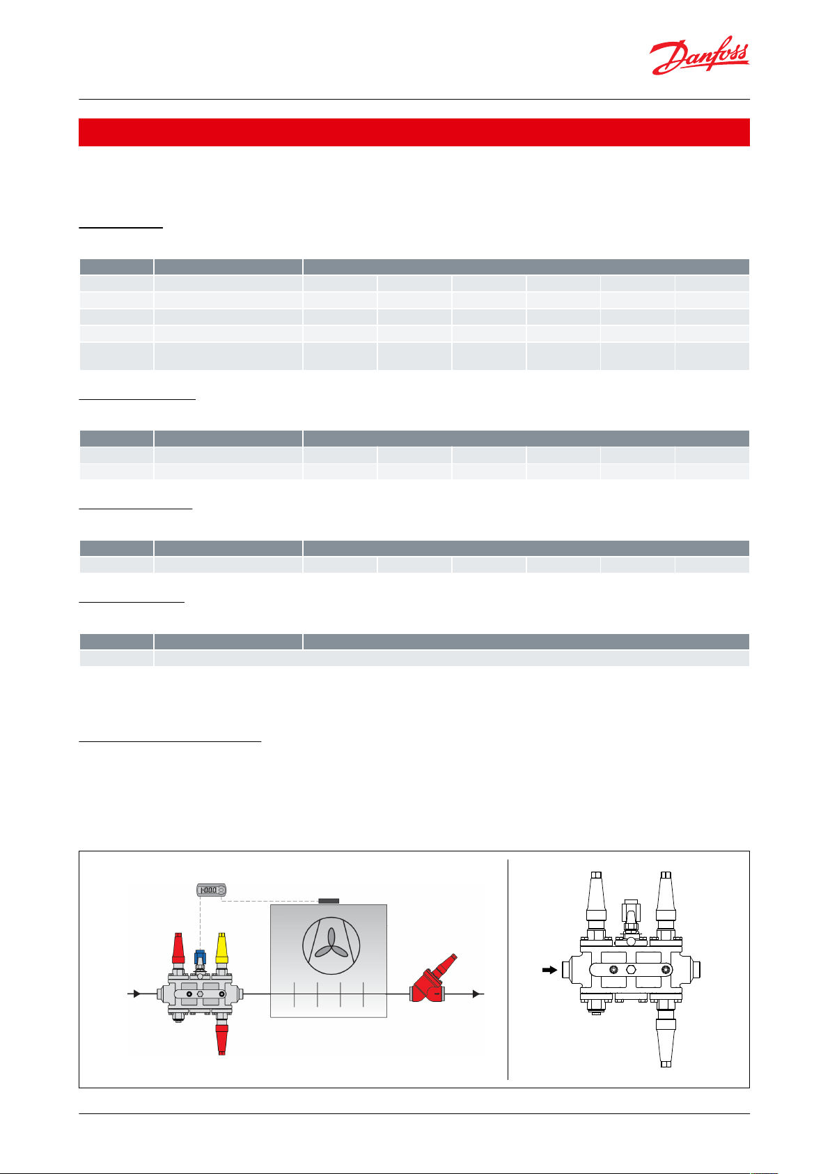
Examples of application:
Liquid feed line
A valve combination for a ooded evaporator operating on/o from a thermostat and with electric defrost is
required. Manual override of the solenoid valve is requested. Common ICF SS congurations for this kind of
application is shown here:
© Danfoss | Climate Solutions | 2021.02 AI243586442520en-000901 | 3
ICFE SS
ICFR SS
ICFF SS
ICFB SS
ICFS SS
ICFS SS
To liquid separator
From
discharge
line
ICLX/GPLX
CVP
ICS
From liquid separator
ICFS SS
ICFE SS
ICFF SS
ICFF SS
ICFS SS
ICFE SS
ICM
ICFF SS
ICFB SS
ICFS SS
To compressor
suction line
AKS 4100
AKS 38
EKE 347
From
receiver
From
evaporator
SVA
SVA
SNV
SNV
SVASVA
SVA
SVA
SFV SFV
DSV
To evaporator
LLG
Liquid separator
Valve station, Type ICF SS 20 and ICF SS 25
NOTE:
Not all valves are shown. Not to be used for construction purposes.
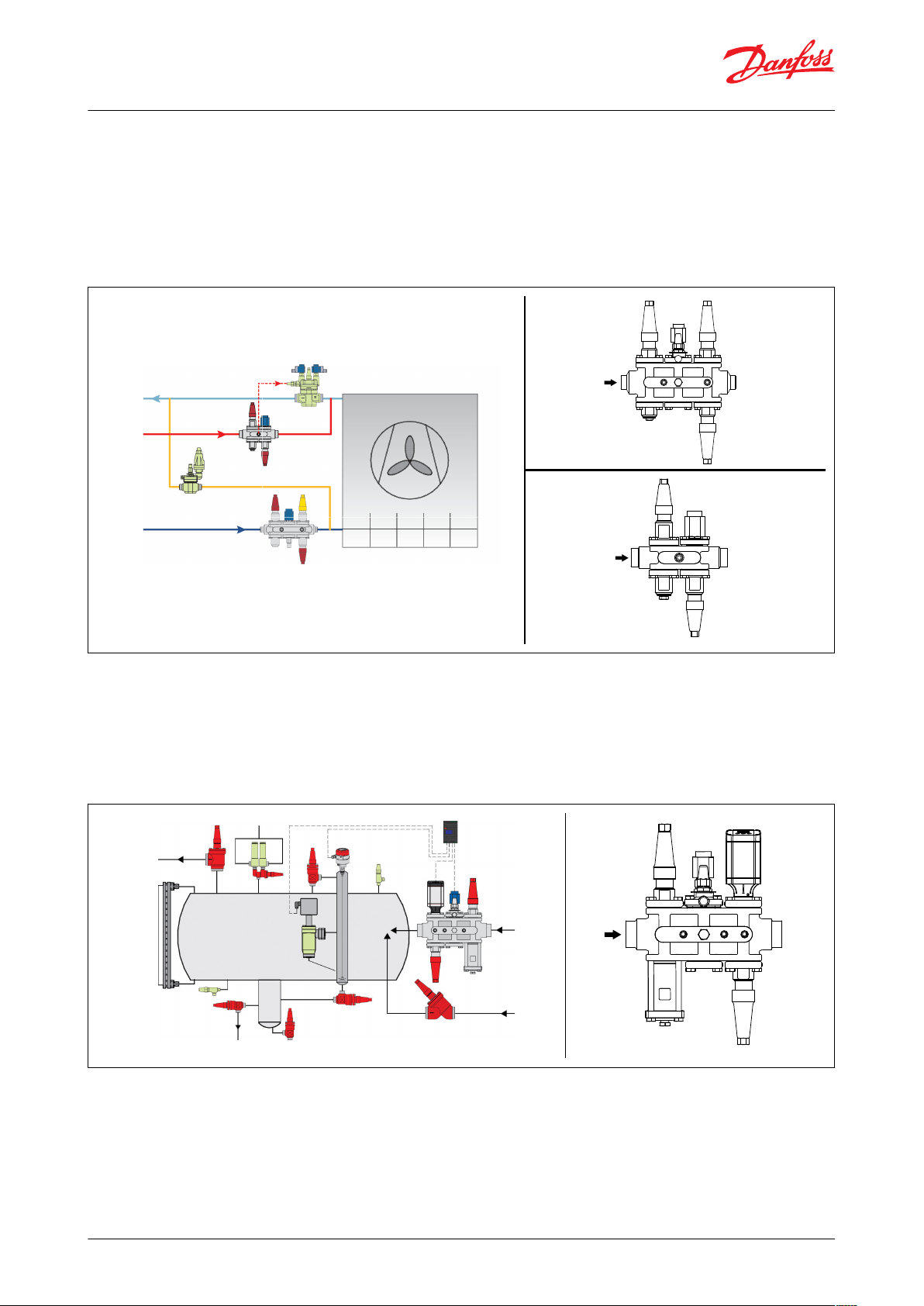
Liquid feed line/Hot gas defrost line
Evaporator with soft opening gas powered valve ICLX in the suction line and hot gas defrost featuring: ICF SS liquid
feed station and ICF SS Hot gas station with side port to power ICLX. ICS+CVP as a defrost regulator (OFV optional
depending on capacity).
Not all valves are shown. Not to be used for construction purposes.
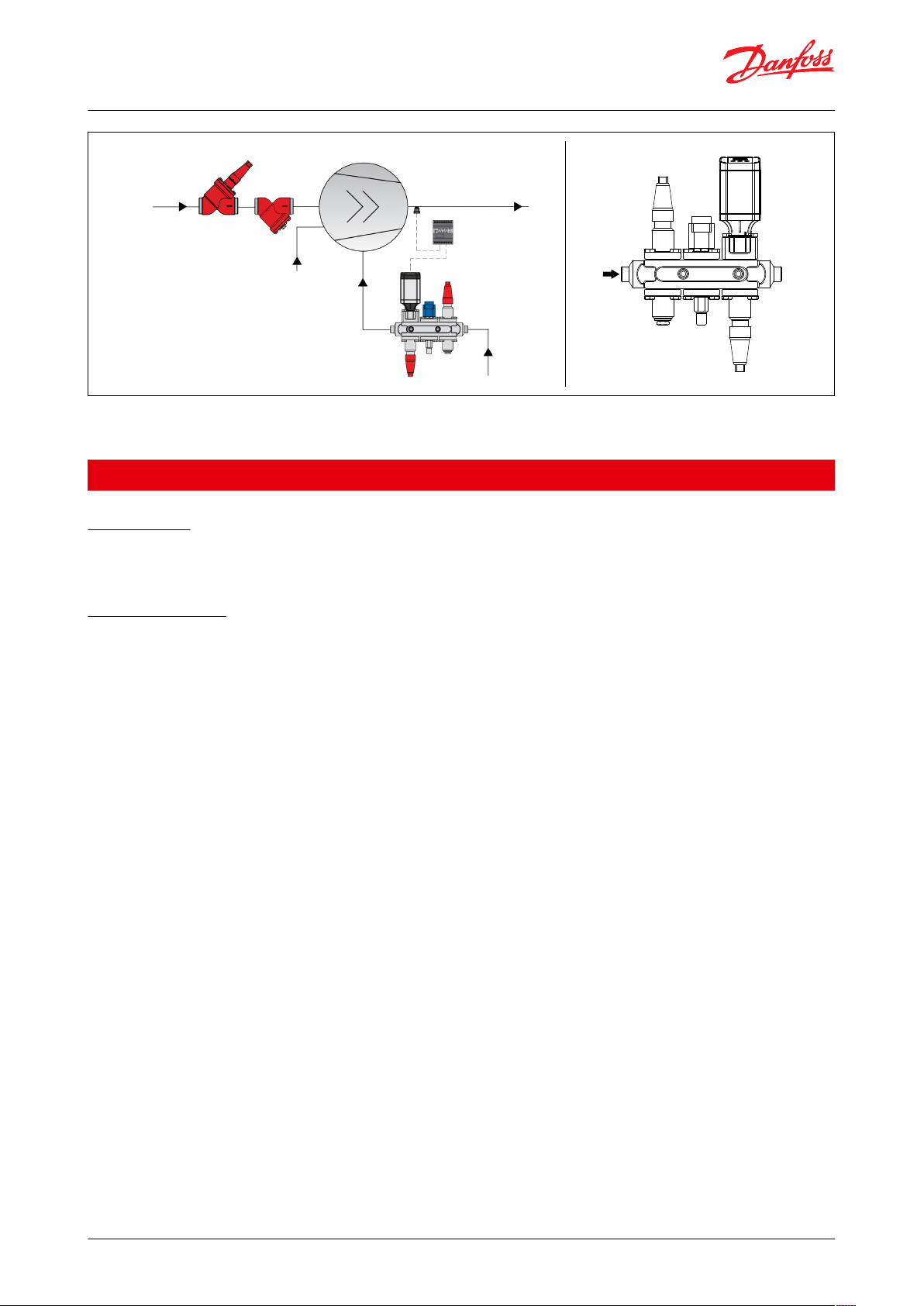
Liquid injection line
A valve combination for liquid injection to separator with electronic injection valve is required. It is requested to
have a solenoid valve in front of the control valve.
NOTE:
Not all valves are shown. Not to be used for construction purposes.
Liquid injection line
A valve combination for compressor liquid injection with electronic injection valve is required. It is a required to
have a solenoid valve in front of the control valve.
NOTE:
© Danfoss | Climate Solutions | 2021.02 AI243586442520en-000901 | 4
ICFS SS
ICFE SS
ICM
ICFF SS ICFO SS
ICFS SS
Compressor
To oil separator
From
receiver
Oil injection
From separator/
evaporator
AKS 21
EKC 361
FIA
SVA
Valve station, Type ICF SS 20 and ICF SS 25
NOTE:
Not all valves are shown. Not to be used for construction purposes.
Media
Refrigerants
Applicable to HCFC, non ammable HFC, R717 (Ammonia) and R744 (CO2). The use of ICF SS valve stations with
ammable hydrocarbons is not recommended.
New refrigerants
Danfoss products are continually evaluated for use with new refrigerants depending on market requirements.
When a refrigerant is approved for use by Danfoss, it is added to the relevant portfolio, and the R number of the
refrigerant (e.g. R513A) will be added to the technical data of the code number. Therefore, products for specic
refrigerants are best checked at store.danfoss.com/en/, or by contacting your local Danfoss representative.
© Danfoss | Climate Solutions | 2021.02 AI243586442520en-000901 | 5
ICF SS 20-4, 25-4
ICF SS 20-6, 25-6
1
1
Pos.
Part
Material
EN
ASTM
1
Housing
Stainless steel
GX5CrNi19-10
EN10213-4
A304
Pos.
Part
Material
EN
ASTM
1
Spindle
Stainless steel
X8CrNiS 18-9
EN 10088
A303
2
Thread part
Stainless steel
3
AL-gasket/Refrig. gasket
4
Bonnet
Stainless steel
X5CrNi 18-10
EN 10272
A304
5
Hex-head bolt
M10 × 25
Stainless steel
A2-70
Type 308
6
Flange
Stainless steel
X5CrNi18-10
EN10088
A304
7
Gasket
Fiber non asbestos
Valve station, Type ICF SS 20 and ICF SS 25
Product specication
Material specication
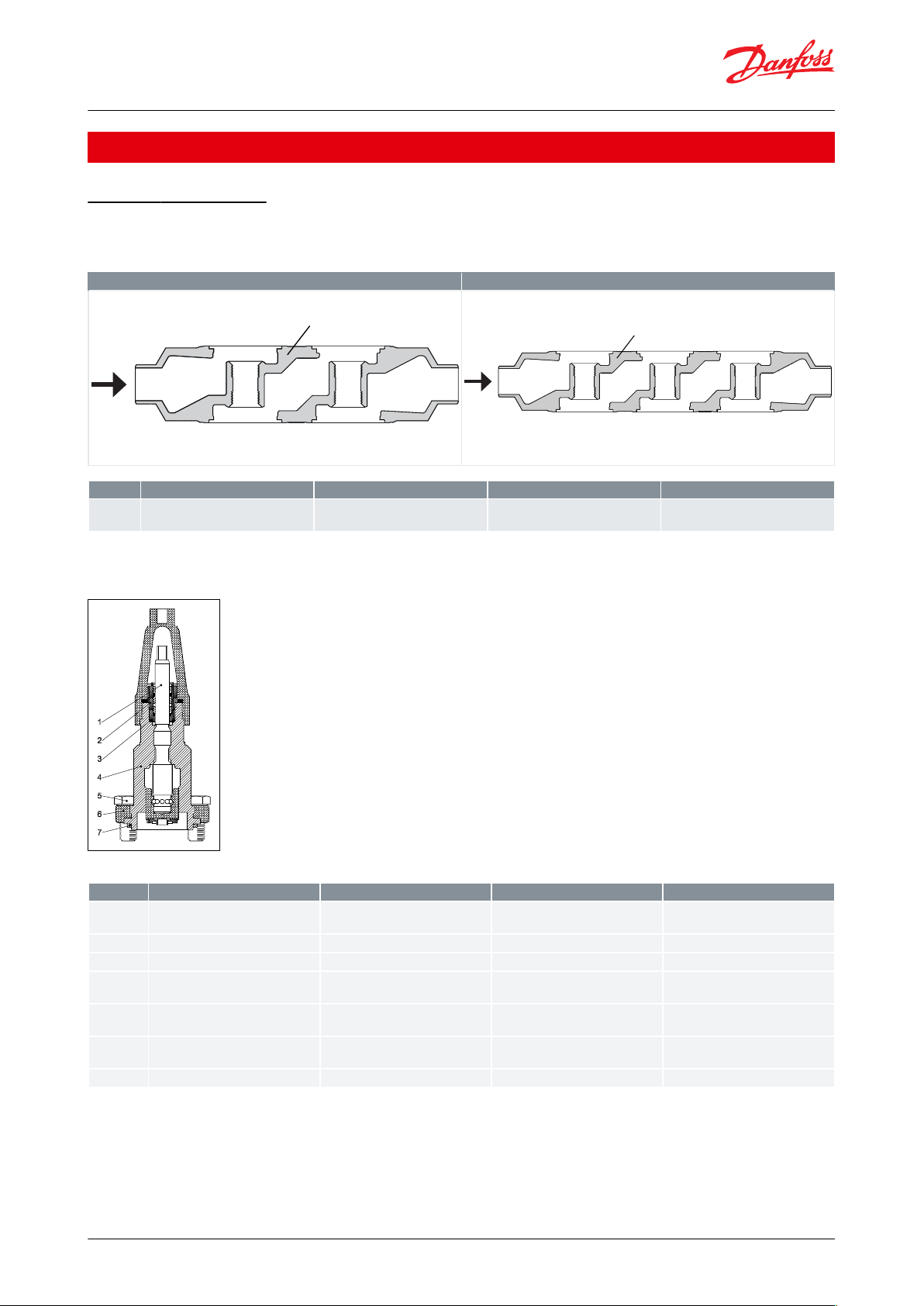
ICF SS housing
Table 5: ICF SS housing
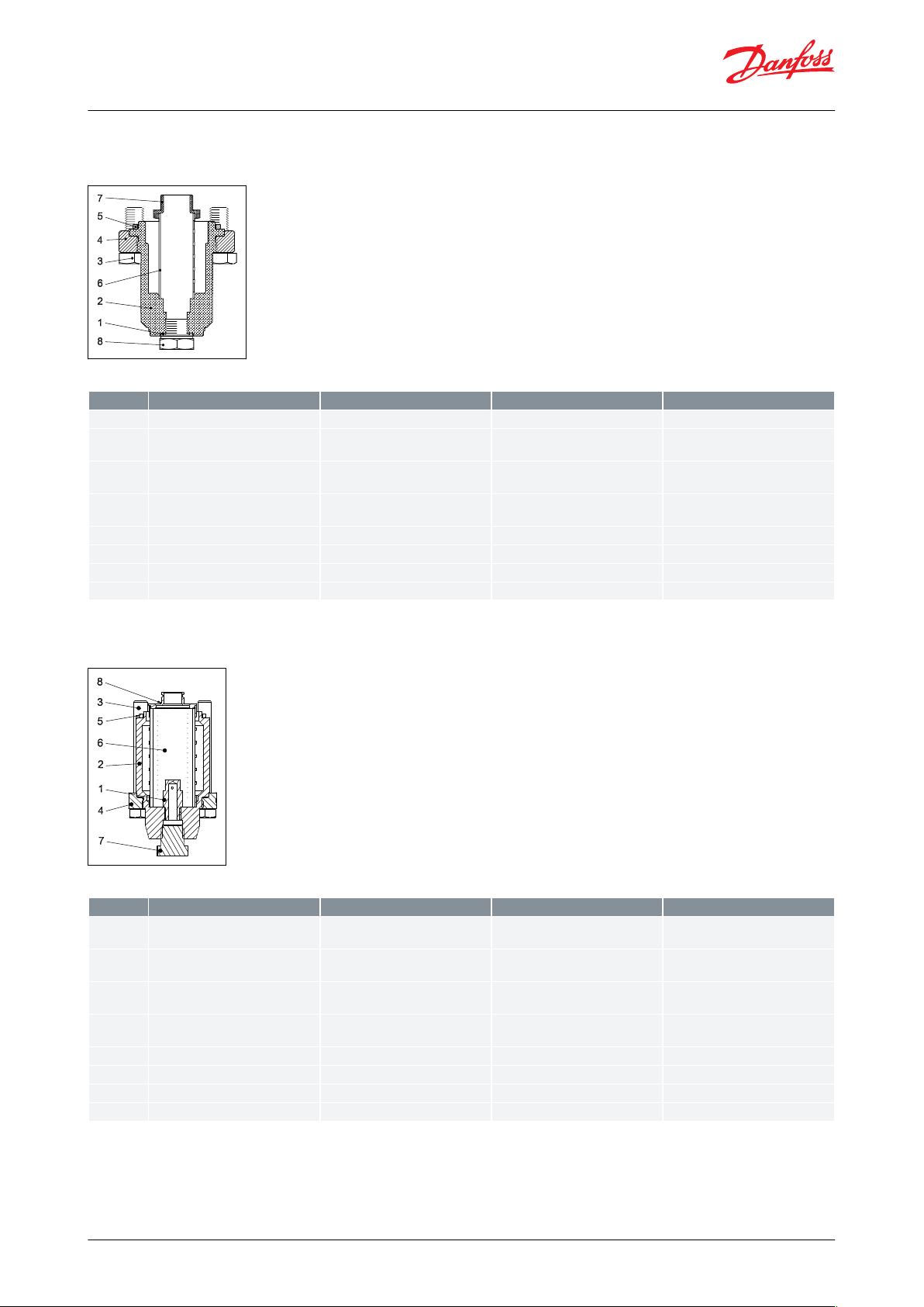
ICFS SS 20 shut-o valve module
Figure 1: ICFS SS 20 shut-o valve module
Table 6: ICFS SS 20 shut-o valve module
© Danfoss | Climate Solutions | 2021.02 AI243586442520en-000901 | 6
Pos.
Part
Material
EN
ASTM
1
Gasket
AL 99 F11
2
Bonnet
Stainless steel
X5CrNi 18-10
EN 10272
A304
3
Hex-head bolt
M10 × 25
Stainless steel
A2-70
Type 308
4
Flange
Stainless steel
X5CrNi18-10
EN10088
A304
5
Gasket
Fiber non asbestos
6
Filter element
Stainless steel 74μ and 150μ
7
Plug
Steel8Plug 1/4” RG for butt-weld
Stainless steel
Pos.
Part
Material
EN
ASTM
1
Dirt protection plug
Steel
11SMn30
EN 10087
Grade 1213 A29
2
Bonnet
Stainless steel
X5CrNi 18-10
EN 10272
A304
3
Hex-head bolt
M12x80
Stainless steel
A2-70
Type 308
4
Flange
Stainless steel
X5CrNi18-10
EN10088
A304
5
Gasket
Fiber non asbestos
6
Filter element
Stainless steel 250m
7
Plug 3/8” NPT
Stainless steel
8
Filter adaptor
Steel
Valve station, Type ICF SS 20 and ICF SS 25
ICFF SS 20 strainer module
Figure 2: ICFF SS 20 strainer module
Table 7: ICFF SS 20 strainer module
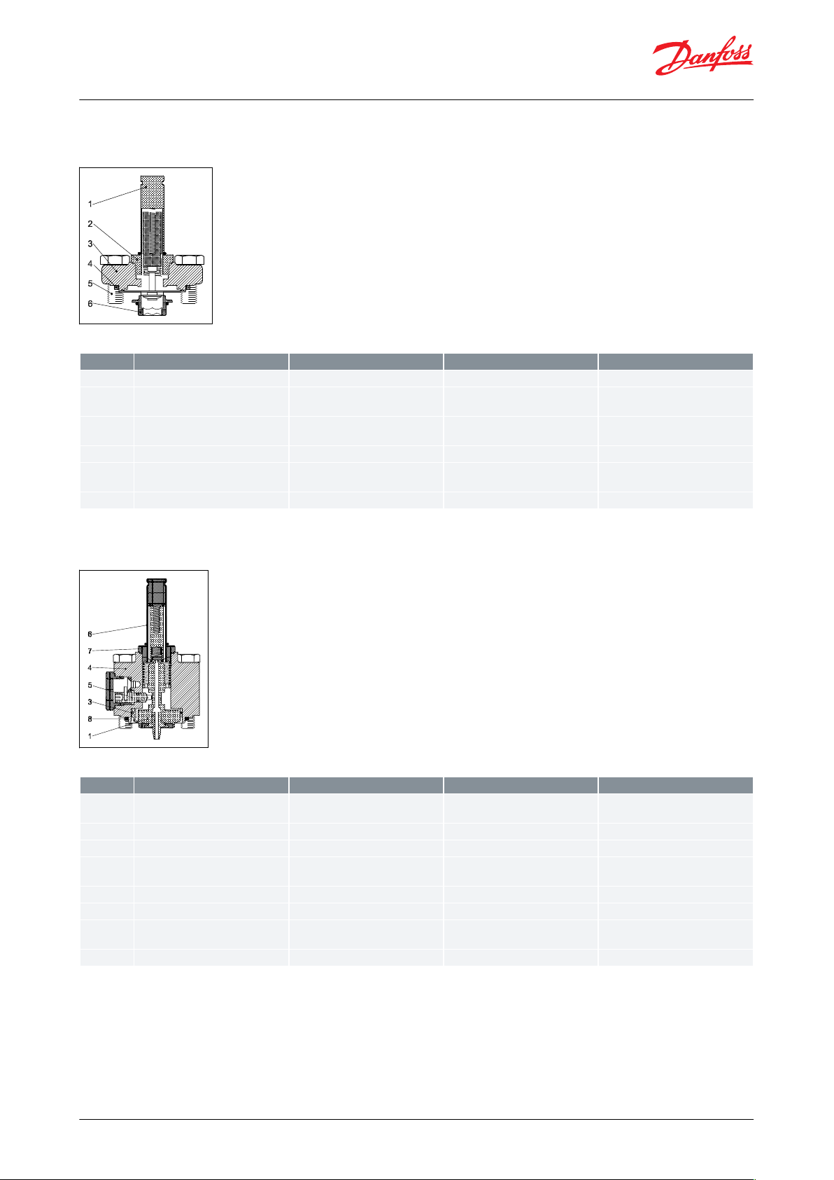
ICFF SS 20E extended strainer module
Figure 3: ICFF SS 20E extended strainer module
Table 8: ICFF SS 20E extended strainer module
© Danfoss | Climate Solutions | 2021.02 AI243586442520en-000901 | 7
Pos.
Part
Material
EN
ASTM
1
Armature tube
Stainless steel
2
Armature tube nut
Stainless steel
X8CrNiS18-9
EN 10088
3
Flange
Stainless steel
X5CrNi18-10
EN10088
A304
4
Gasket
Fiber non asbestos
5
Hex-Head bolt
M10 × 25
Stainless steel
A2-70
Type 308
6
Seat
High density polymer
Pos.
Part
Material
EN
ASTMf
1
Piston
Steel
11SMn30 EN
EN 10025
2
Seat
Teon3Piston ring
4
Bonnet cylinder
Stainless steel
X5CrNi18-10
EN10088
A304
5
Manual opener
Steel6Armature tube
Stainless steel
7
Armature tube nut
Stainless steel
X2CrNi19-11
EN10216
A320
8
Gasket
Fiber non asbestos
Valve station, Type ICF SS 20 and ICF SS 25
ICFE SS 20 solenoid valve module
Figure 4: ICFE SS 20 solenoid valve module
Table 9: ICFE SS 20 solenoid valve module
ICFE SS 20H solenoid valve module
Figure 5: ICFE SS 20H solenoid valve module
Table 10: ICFE SS 20H solenoid valve module
© Danfoss | Climate Solutions | 2021.02 AI243586442520en-000901 | 8
Pos.
Part
Material
EN
ASTM
1
Seal cap
Stainless steel
2
Gland nut
Steel3Seal cap gasket
Nylon
Polyamid A6
Polyamid PA6
4
Sealing ring
Teon
PTFE
PTFE5Gasket
Fiber non asbestos
CR
CR6Spindle
Stainless steel
X8CrNiS 18-9 EN 10088
A3037Hex-head bolt M10 × 25
Stainless steel
A2-70
Type 308
8
Flange
Stainless steel
X5CrNi18-10 EN10088
A304
Pos.
Part
Material
EN
ASTM
1
Spindle
Stainless steel
X8CrNiS 18-9
EN 10088
A303
2
Thread part
Stainless steel
3
AL-gasket
4
Bonnet
Stainless steel
X5CrNi 18-10
EN 10272
A304
5
Hex-head bolt
M10 × 25
Stainless steel
A2-70
Type 308
6
Flange
Stainless steel
X5CrNi18-10
EN10088
A304
7
Gasket
Fiber non asbestos
8
Seat
High density polymer
Valve station, Type ICF SS 20 and ICF SS 25
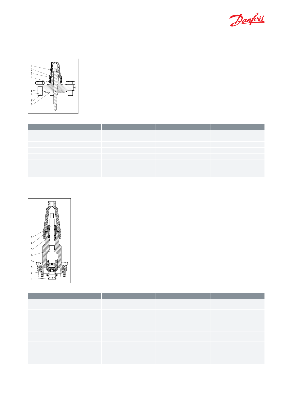
ICFO SS 20 manual opening module
Figure 6: ICFO SS 20 manual opening module
Table 11: ICFO SS 20 manual opening module
ICFR SS 20 manual regulating valve module, A or B
Figure 7: ICFR SS 20 manual regulating valve module, A or B
Table 12: ICFR SS 20 manual regulating valve module, A or B
© Danfoss | Climate Solutions | 2021.02 AI243586442520en-000901 | 9

Pos.
Part
Material
EN
ASTM
1
Armature tube
Stainless steel
2
Armature tube nut
Stainless steel
X8CrNiS18-9
EN 10088
3
Hex-head bolt
M10 × 25
Stainless steel
A2-70
Type 308
4
Flange
Stainless steel
X5CrNi18-10
EN10088
A304
5
Gasket
Fiber non asbestos
6
Adaptor
Stainless steel
Pos.
Part
Material
EN
ASTM
1
Bonnet
Stainless steel
X5CrNi 18-10
EN 10272
A304
2
Hex-head bolt
M10 × 25
Stainless steel
A2-70
Type 308
3
Flange
Stainless steel
X5CrNi18-10
EN10088
A304
4
Gasket
Fiber non asbestos
Valve station, Type ICF SS 20 and ICF SS 25
ICFA SS 20 electronic expansion valve module
Figure 8: ICFA SS 20 electronic expansion valve module
Table 13: ICFA SS 20 electronic expansion valve module
ICFC SS 20 check valve module
Figure 9: ICFC SS 20 check valve module
Table 14: ICFC SS 20 check valve module
© Danfoss | Climate Solutions | 2021.02 AI243586442520en-000901 | 10

Pos.
Part
Material
EN
ASTM
1
Spindle
Stainless steel
X8CrNiS 18-9
EN 10088
A303
2
Thread part
Stainless steel
3
AL-gasket
4
Bonnet
Stainless steel
X5CrNi 18-10
EN 10272
A304
5
Hex-head bolt
M10 × 25
Stainless steel
A2-70
Type 308
6
Flange
Stainless steel
X5CrNi18-10
EN10088
A304
7
Gasket
Fiber non asbestos
Pos.
Part
Material
EN
ASTM
1
Adapter
Stainless steel
X5CrNi18-10
EN 10088
A240
2
Hex-head bolt
M10 × 55
Stainless steel
A2-70
Type 308
3
O-ring
Chloroprene
4
Bonnet
Stainless steel
X5CrNi 18-10
EN 10088
A304
5
Gasket
Fiber non asbestos
6
Seat
High density polymer
Valve station, Type ICF SS 20 and ICF SS 25
ICFN SS 20 stop & check valve module
Figure 10: ICFN SS 20 stop & check valve module
Table 15: ICFN SS 20 stop & check valve module
ICM SS 20-A, 20-B, 20-C, 20-A33 or 20-B66 motor valve module
Figure 11: ICM SS 20-A, 20-B, 20-C, 20-A33 or 20-B66 motor valve module
Table 16: ICM SS 20-A, 20-B, 20-C, 20-A33 or 20-B66 motor valve module
© Danfoss | Climate Solutions | 2021.02 AI243586442520en-000901 | 11

Pos.
Part
Material
EN
ASTM
1
Hex-head bolt
M10 × 25
Stainless Steel
A2-70
Type 308
2
Flange
Stainless steel
X5CrNi18-10
EN10088
A304
3
Gasket
Fiber non asbestos
Pos.
Part
Material
EN
ASTM
1
Hex-head bolt
M10 × 25
Stainless Steel
A2-70
Type 308
2
Flange
Stainless steel
X5CrNi18-10
EN10088
A304
3
Gasket
Fiber non asbestos
4
Weld connection
Stainless Steel
Pos.
Part
Material
EN
ASTM
1
Spindle
Stainless steel
X8CrNiS 18-9
EN 10088
A303
2
Thread part
Stainless steel
3
O-ring
Chloroprene
Valve station, Type ICF SS 20 and ICF SS 25
ICFB SS 20 blank top cover
Figure 12: ICFB SS 20 blank top cover
Table 17: ICFB SS 20 blank top cover
ICFW SS 20D welding module, 20 DIN
Figure 13: ICFW SS 20D welding module, 20 DIN
Table 18: ICFW SS 20D welding module, 20 DIN
ICFS SS 25 shut-o valve module
Figure 14: ICFS SS 25 shut-o valve module
Table 19: ICFS SS 25 shut-o valve module
© Danfoss | Climate Solutions | 2021.02 AI243586442520en-000901 | 12

Pos.
Part
Material
EN
ASTM
4
Bonnet
Stainless steel
X5CrNi 18-10
EN 10272
A304
5
Hex-head bolt M12 × 30
Stainless steel
A2-70
Type 308
6
Flange
Stainless steel
X5CrNi18-10
EN10088
A304
7
Gasket
Fiber non asbestos
Pos.
Part
Material
EN
ASTM
1
Al. Gasket
AL 99 F11
2
Bonnet
Stainless steel
X5CrNi 18-10
EN 10272
A304
3
Hex-head bolt
M12 × 30
Stainless steel
A2-70
Type 308
4
Flange
Stainless steel
X5CrNi18-10
EN10088
A304
5
Gasket
Fiber non asbestos
6
Filter element
Stainless steel 150m
7
Plug
1/4” RG for butt-weld
Stainless steel
Pos.
Part
Material
EN
ASTM
1
Dirt protection plug
Steel
11SMn30
EN 10087
Grade 1213 A29
2
Bonnet
Stainless steel
X5CrNi 18-10
EN 10222
A304
3
Hex-head bolt
M12x140
Stainless steel
A2-70
Type 308
4
Flange
Stainless steel
X5CrNi18-10
EN10088
A304
Valve station, Type ICF SS 20 and ICF SS 25
ICFF SS 25 strainer module
Figure 15: ICFF SS 25 strainer module
Table 20: ICFF SS 25 strainer module
ICFF SS 25E extended strainer module
Figure 16: ICFF SS 25E extended strainer module
Table 21: ICFF SS 25E extended strainer module
© Danfoss | Climate Solutions | 2021.02 AI243586442520en-000901 | 13

Pos.
Part
Material
EN
ASTM
5
Gasket
Fiber non asbestos
6
Filter element
Stainless steel 250m
7
Plug 3/8” NPT
Stainless steel
Pos.
Part
Material
EN
ASTM
1
Armature tube
Stainless steel
2
Armature tube nut
Stainless steel
X8CrNiS18-9
EN 10088
3
Bonnet
Stainless steel
X5CrNi 18-10
EN 10222
A304
4
Gasket
Fiber non asbestos
5
Hex-Head bolt
M10 × 30
Stainless steel
A2-70
Type 308
6
Seat
High density polymer
Pos.
Part
Material
EN
ASTM
1
Spindle
Stainless steel
X8CrNiS 18-9
EN 10088
A303
2
Thread part
Stainless steel
3
O-ring
Chloroprene
4
Bonnet
Stainless steel
X5CrNi 18-10
EN 10272
A304
5
Hex-head bolt
M12 × 30
Stainless steel
A2-70
Type 308
Valve station, Type ICF SS 20 and ICF SS 25
ICFE SS 25 solenoid valve module
Figure 17: ICFE SS 25 solenoid valve module
Table 22: ICFE SS 25 solenoid valve module
ICFR SS 25 manual regulating valve module, A or B
Figure 18: ICFR SS 25 manual regulating valve module, A or B
Table 23: ICFR SS 25 manual regulating valve module, A or B
© Danfoss | Climate Solutions | 2021.02 AI243586442520en-000901 | 14

Pos.
Part
Material
EN
ASTM
6
Flange
Stainless steel
X5CrNi18-10
EN10088
A304
7
Gasket
Fiber non asbestos
8
Seat
High density polymer
Pos.
Part
Material
EN
ASTM
1
Bonnet
Stainless steel
X5CrNi 18-10
EN 10272
A304
2
Hex-head bolt
M12 × 30
Stainless steel
A2-70
Type 308
3
Flange
Stainless steel
X5CrNi18-10
EN10088
A304
4
Gasket
Fiber non asbestos
Pos.
Part
Material
EN
ASTM
1
Spindle
Stainless steel
X8CrNiS 18-9
EN 10088
A303
2
Thread part
Stainless steel
3
O-ring
Chloroprene
4
Bonnet
Stainless steel
X5CrNi 18-10
EN 10272
A304
5
Hex-head bolt
M12 × 30
Stainless steel
A2-70
Type 308
6
Flange
Stainless steel
X5CrNi18-10
EN10088
A304
7
Gasket
Fiber non asbestos
Valve station, Type ICF SS 20 and ICF SS 25
ICFC SS 25 check valve module
Figure 19: ICFC SS 25 check valve module
Table 24: ICFC SS 25 check valve module
ICFN SS 25 stop & check valve module
Figure 20: ICFN SS 25 stop & check valve module
Table 25: ICFN SS 25 stop & check valve module
© Danfoss | Climate Solutions | 2021.02 AI243586442520en-000901 | 15

Pos.
Part
Material
EN
ASTM
1
Adapter
Stainless steel
X5CrNi18-10
EN 10088
A240
2
Hex-head bolt
M12 × 30
Stainless steel
A2-70
Type 308
3
O-ring
Chloroprene
4
Bonnet
Stainless steel
X5CrNi18-10
EN10088
A304
5
Gasket
Fiber non asbestos
6
Seat
High density polymer
Pos.
Part
Material
EN
ASTM
1
Hex-head bolt
M10 × 30
Stainless Steel
A2-70
Type 308
2
Flange
Stainless steel
X5CrNi18-10
EN10088
A304
3
Gasket
Fiber non asbestos
Valve station, Type ICF SS 20 and ICF SS 25
ICM SS 25-A or B motor valve module
Figure 21: ICM SS 25-A or B motor valve module
Table 26: ICM SS 25-A or B motor valve module
ICFB SS 25 blank top cover
Figure 22: ICFB SS 25 blank top cover
Table 27: ICFB SS 25 blank top cover
ICFW SS 25 welding module, 25 DIN
Figure 23: ICFW SS 25 welding module, 25 DIN
© Danfoss | Climate Solutions | 2021.02 AI243586442520en-000901 | 16

Pos.
Part
Material
EN
ASTM
1
Hex-head bolt
M10 × 30
Stainless Steel
A2-70
Type 308
2
Flange
Stainless steel
X5CrNi18-10
EN10088
A304
3
Gasket
Fiber non asbestos
4
Weld connection
Stainless steel
ø
Size
SizeØDTØDTmmin.mmmm
in.
in.
20
(3/4)
26.9
2.3
1.059
0.091251
33.7
2.6
1.327
0.10332(1 1/4)
42.4
2.6
1.669
0.102401 1/2
48.3
2.6
1.902
0.103
Size
SizeØDTØDT
Schedule
mm
in.mmmm
in.
in.
20
(3/4)
26.9
2.9
1.059
0.11
40251
33.7
3.5
1.327
0.14
40321 1/4
42.4
3.6
1.669
0.14
40401 1/2
48.3
3.7
1.902
0.15
40
Valve station, Type ICF SS 20 and ICF SS 25
Table 28: ICFW SS 25 welding module, 25 DIN
Connections
D: Butt-weld DIN (EN 10220)
Figure 24: D: Butt-weld DIN (EN 10220)
Table 29: D: Butt-weld DIN (EN 10220)
A: Butt-weld ANSI (B 36.19)
Figure 25: A: Butt-weld ANSI (B 36.19)
Table 30: A: Butt-weld ANSI (B 36.19)
© Danfoss | Climate Solutions | 2021.02 AI243586442520en-000901 | 17

260 mm
(10.2 in.)
Valve station, Type ICF SS 20 and ICF SS 25
Dimensions and weights
ICF SS 20-6
Figure 26: ICF SS 20-6
This example indicates the maximum dimensions for the ICF SS valve stations.
ICF SS 20-4
Figure 27: ICF SS 20-4
© Danfoss | Climate Solutions | 2021.02 AI243586442520en-000901 | 18

252 mm
(9.9 in.)
273 mm
(10.7 in.)
59 mm
(2.3 in.)
70 mm
(2.8 in.)
356 mm
(14.0 in.)
252 mm
(9.9 in.)
273 mm
(10.7 in.)
58 mm
(2.3 in.)
70 mm
(2.8 in.)
266 mm
(10.5 in.)
Valve station, Type ICF SS 20 and ICF SS 25
ICF SS 25-6
Figure 28: ICF SS 25-6
ICF SS 25-4
Figure 29: ICF SS 25-4
© Danfoss | Climate Solutions | 2021.02 AI243586442520en-000901 | 19

ICF SS 20 - 6 - 3
Type
Number of module ports
Application reference number
(see the below overview)
Housing size
Type
# of
mod‐
ules
Appl.
#
Connec‐
tion size
Connection
type
Module location
Weight
Code
number
[in.]
[mm]M1M2M3M4M5M6kglbs
ICF SS 20
6
1RA
3
⁄4
20
Butt-weld DIN-
EN 10220
ICFS 20
ICFF 20
ICFE 20
ICFO 20
ICFR 20A
ICFS 20
9.5
20.9
027L4700
ICF SS 20
6
1RA125
Butt-weld DIN-
EN 10220
ICFS 20
ICFF 20
ICFE 20
ICFO 20
ICFR 20A
ICFS 20
9.7
21.3
027L4701
ICF SS 20
6
1RA
3
⁄4
20
Butt-weld ANSI
(B 36.19)
ICFS 20
ICFF 20
ICFE 20
ICFO 20
ICFR 20A
ICFS 20
10.4
22.9
027L3555
Valve station, Type ICF SS 20 and ICF SS 25
Ordering
Below Nomenclature show the generic conguration and application by identication of housing size, type and
application group.
This designation is often used for discussion on possible solutions and will be the nal identication on the valve
label (see label example).
Figure 30: Label example:
For ordering, connection size and type must be chosen to get the nal identication. The nal identication is
done by code number only. See (Page 20 to Page 25)
Code number selection
To determine the correct ICF SS valve station follow steps 1 through 5.
Step 1 Determine application and function requirements
• Line: Pumped liquid, Liquid Injection, Hot gas defrost, Liquid DX etc
• Control: On/o solenoid valve, motorised valve
• Defrost: Electric or hot gas
NOTE:
From the above determine the application reference number. See (Page 20 to Page 25)
Step 2 Selection criteria - Please use Coolselector®2
Download the software from: http://refrigerationandairconditioning.danfoss.com/support-center/apps-andsoftware/coolselector/
• Refrigerant
• Capacity
• Temperature
• Circulation rate
NOTE:
From the above determine the valve station required, e.g.: ICF SS 20 complete with ICM SS 20-C
Step 3 Establish connection sizes and type
• DIN butt-weld / ANSI butt-weld
• 20 (¾ in.), 25 (1 in.), 32 (1 ¼ in.) or 40 (1 ½ in.)
Step 4 Establish code number. See (Page 20 to Page 25)
Liquid feed
Table 31: Application 1: Liquid feed (no hot gas defrost)
© Danfoss | Climate Solutions | 2021.02 AI243586442520en-000901 | 20

Type
# of
mod‐
ules
Appl.
#
Connec‐
tion size
Connection
type
Module location
Weight
Code
number
[in.]
[mm]M1M2M3M4M5M6kglbs
ICF SS 20
6
1RA125
Butt-weld ANSI
(B 36.19)
ICFS 20
ICFF 20E
ICFE 20
ICFO 20
ICFR 20A
ICFS 20
9.9
21.8
027L3556
ICF SS 20
6
1HRB125
Butt-weld ANSI
(B 36.19)
ICFS 20
ICFF 20E
ICFE 20H
ICFB 20
ICFR 20B
ICFS 20
10.9
24
027L3578
ICF SS 20
6
1HRB
1
1
⁄4
32
Butt-weld ANSI
(B 36.19)
ICFS 20
ICFF 20E
ICFE 20H
ICFB 20
ICFR 20B
ICFS 20
10.9
24
027L3557
ICF SS 25
6
1RA125
Butt-weld ANSI
(B 36.19)
ICFS 25
ICFF 25E
ICFE 25
ICFB 25
ICFR 25A
ICFS 25
24.1
53
027L3568
ICF SS 25
6
1RA
1
1
⁄4
32
Butt-weld ANSI
(B 36.19)
ICFS 25
ICFF 25E
ICFE 25
ICFB 25
ICFR 25A
ICFS 25
23.8
52.4
027L3569
ICF SS 25
6
1RB
1
1
⁄4
32
Butt-weld ANSI
(B 36.19)
ICFS 25
ICFF 25E
ICFE 25
ICFB 25
ICFR 25B
ICFS 25
24.2
53.2
027L3584
ICF SS 25
6
1RB1½40
Butt-weld ANSI
(B 36.19)
ICFS 25
ICFF 25E
ICFE 25
ICFB 25
ICFR 25B
ICFS 25
23.8
52.4
027L3570
Type
# of
mod‐
ules
Appl.#Connec‐
tion size
Connection
type
Module location
Weight
Code
number
[in.]
[mm]M1M2M3M4M5M6kglbs
ICF SS 20
6
2RA
3
⁄4
20
Butt-weld DIN-
EN 10220
ICFS 20
ICFF 20
ICFE 20
ICFO 20
ICFR 20A
ICFN 20
10
22.1
027L3428
ICF SS 20
6
2RA125
Butt-weld DIN-
EN 10220
ICFS 20
ICFF 20E
ICFE 20
ICFO 20
ICFR 20A
ICFN 20
10
22.1
027L3445
ICF SS 20
6
2RA125
Butt-weld DIN-
EN 10220
ICFS 20
ICFF 20
ICFE 20
ICFO 20
ICFR 20A
ICFN 20
9.7
21.3
027L4758
ICF SS 20
6
2HRB
1
1
⁄4
32
Butt-weld DIN-
EN 10220
ICFS 20
ICFF 20
ICFE 20H
ICFB 20
ICFR 20B
ICFN 20
9.2
20.2
027L4759
ICF SS 25
6
2RB
1
1
⁄4
32
Butt-weld DIN-
EN 10220
ICFS 25
ICFF 25
ICFE 25
ICFB 25
ICFR 25B
ICFN 25
23.9
52.6
027L4766
ICF SS 20
6
2RA
3
⁄4
20
Butt-weld ANSI
(B 36.19)
ICFS 20
ICFF 20E
ICFE 20
ICFO 20
ICFR 20A
ICFN 20
10.1
22.2
027L3571
ICF SS 20
6
2RA125
Butt-weld ANSI
(B 36.19)
ICFS 20
ICFF 20E
ICFE 20
ICFO 20
ICFR 20A
ICFN 20
9.9
21.8
027L3572
Type
# of
mod‐
ules
Appl.
#
Connec‐
tion size
Connection
type
Module location
Weight
Code
number
[in.]
[mm]M1M2M3M4M5M6kglbs
ICF SS 20
6
3RA
3
⁄4
20
Butt-weld DIN-
EN 10220
ICFS 20
ICFF 20
ICFE 20
ICFC 20
ICFR 20A
ICFS 20
9.6
21.1
027L4702
ICF SS 20
6
3RA125
Butt-weld DIN-
EN 10220
ICFS 20
ICFF 20
ICFE 20
ICFC 20
ICFR 20A
ICFS 20
9.7
21.3
027L4703
ICF SS 20
6
3HRA125
Butt-weld DIN-
EN 10220
ICFS 20
ICFF 20
ICFE 20H
ICFC 20
ICFR 20A
ICFS 20
10.6
23.3
027L4717
ICF SS 25
6
3RA125
Butt-weld DIN-
EN 10220
ICFS 25
ICFF 25
ICFE 25
ICFC 25
ICFR 25A
ICFS 25
23.4
51.5
027L4724
ICF SS 25
6
3RA
1
1
⁄4
32
Butt-weld DIN-
EN 10220
ICFS 25
ICFF 25
ICFE 25
ICFC 25
ICFR 25A
ICFS 25
23.2
51
027L4760
ICF SS 25
6
3RB
1
1
⁄4
32
Butt-weld DIN-
EN 10220
ICFS 25
ICFF 25
ICFE 25
ICFC 25
ICFR 25B
ICFS 25
23.8
52.4
027L4725
ICF SS 25
6
3RB
1
1
⁄2
40
Butt-weld DIN-
EN 10220
ICFS 25
ICFF 25
ICFE 25
ICFC 25
ICFR 25B
ICFS 25
24
52.8
027L4761
ICF SS 25
6
3RB
1
1
⁄2
40
Butt-weld DIN-
EN 10220
ICFS 25
ICFF 25E
ICFE 25
ICFC 25
ICFR 25B
ICFS 25
24.7
54.3
027L4191
ICF SS 20
6
3HRB
3
⁄4
20
Butt-weld ANSI
(B 36.19)
ICFS 20
ICFF 20E
ICFE 20H
ICFC 20
ICFR 20B
ICFS 20
10.7
23.5
027L3579
ICF SS 20
6
3HRB125
Butt-weld ANSI
(B 36.19)
ICFS 20
ICFF 20E
ICFE 20H
ICFC 20
ICFR 20B
ICFS 20
11.2
24.6
027L3580
ICF SS 20
6
3HRB
1
1
⁄4
32
Butt-weld ANSI
(B 36.19)
ICFS 20
ICFF 20E
ICFE 20H
ICFC 20
ICFR 20B
ICFS 20
11.3
24.9
027L3581
ICF SS 25
6
3RA125
Butt-weld ANSI
(B 36.19)
ICFS 25
ICFF 25E
ICFE 25
ICFC 25
ICFR 25A
ICFS 25
24.2
53.2
027L3585
Valve station, Type ICF SS 20 and ICF SS 25
Table 32: Application 2: Liquid feed
Table 33: Application 3: Liquid feed
© Danfoss | Climate Solutions | 2021.02 AI243586442520en-000901 | 21

Type
# of
mod‐
ules
Appl.
#
Connec‐
tion size
Connection
type
Module location
Weight
Code
number
[in.]
[mm]M1M2M3M4M5M6kglbs
ICF SS 25
6
3RA
1
1
⁄4
32
Butt-weld ANSI
(B 36.19)
ICFS 25
ICFF 25E
ICFE 25
ICFC 25
ICFR 25A
ICFS 25
24.1
53
027L3586
ICF SS 25
6
3RB
1
1
⁄4
32
Butt-weld ANSI
(B 36.19)
ICFS 25
ICFF 25E
ICFE 25
ICFC 25
ICFR 25B
ICFS 25
24.1
53
027L3587
ICF SS 25
6
3RB1½40
Butt-weld ANSI
(B 36.19)
ICFS 25
ICFF 25E
ICFE 25
ICFC 25
ICFR 25B
ICFS 25
24.2
53.2
027L3588
Type
# of
mod‐
ules
Appl. #
Connection
size
Connection type
Module location
Weight
Code
number
[in.]
[mm]M1M2M3M4kglbs
ICF SS 20
4
10RA
3
⁄4
20
Butt-weld DIN-EN
10220
ICFS 20
ICFF 20
ICFE 20
ICFR 20B
7.4
16.2
027L3440
ICF SS 20
4
10RA125
Butt-weld DIN-EN
10220
ICFS 20
ICFF 20
ICFE 20
ICFR 20A
7.2
15.8
027L4709
ICF SS 25
4
10RA125
Butt-weld DIN-EN
10220
ICFS 25
ICFF 25
ICFE 25
ICFR 25A
15.9
35
027L4731
ICF SS 25
4
10RB
1
1
⁄4
32
Butt-weld DIN-EN
10220
ICFS 25
ICFF 25
ICFE 25
ICFR 25B
15.4
33.9
027L4732
ICF SS 25
4
10RA125
Butt-weld DIN-EN
10220
ICFS 25
ICFF 25E
ICFE 25
ICFR 25A
16.2
35.7
027L4590
ICF SS 20
4
10HRB
3
⁄4
20
Butt-weld ANSI (B
36.19)
ICFS 20
ICFF 20E
ICFE 20H
ICFR 20B
8.4
18.5
027L3582
ICF SS 20
4
10HRB125
Butt-weld ANSI (B
36.19)
ICFS 20
ICFF 20E
ICFE 20H
ICFR 20B
7.8
17.2
027L3583
ICF SS 25
4
10RA125
Butt-weld ANSI (B
36.19)
ICFS 25
ICFF 25E
ICFE 25
ICFR 25A
15.8
34.8
027L3592
ICF SS 25
4
10RB
1
1
⁄4
32
Butt-weld ANSI (B
36.19)
ICFS 25
ICFF 25E
ICFE 25
ICFR 25B
16.2
35.6
027L3593
ICF SS 25
4
10RB1½40
Butt-weld ANSI (B
36.19)
ICFS 25
ICFF 25E
ICFE 25
ICFR 25B
16.2
35.6
027L3594
Type
# of
mod‐
ules
Appl.#Connection
size
Connection type
Module location
Weight
Code
number
[in.]
[mm]M1M2M3M4M5M6kglbs
ICF SS 25
6
15RA125
Butt-weld DIN-EN
10220
ICFS 25
ICFF 25
ICFE 25
ICFC 25
ICFW 25D
ICFR 25A
21.8
48
027L4733
ICF SS 25
6
15RB
1
1
⁄4
32
Butt-weld DIN-EN
10220
ICFS 25
ICFF 25
ICFE 25
ICFC 25
ICFW 25D
ICFR 25B
22.7
49.9
027L4734
Type
# of
mod‐
ules
Appl.
#
Connection
size
Connection
type
Module location
Weight
Code
number
[in.]
[mm]M1M2M3M4M5M6kglbs
ICF SS 20
6
5MA33
3
⁄4
20
Butt-weld DIN-
EN 10220
ICFS 20
ICFF 20-74
ICFE 20
ICFO 20
ICM 20-A33
ICFS 20
9.8
21.6
027L4714
ICF SS 20
6
5MB66
3
⁄4
20
Butt-weld DIN-
EN 10220
ICFS 20
ICFF 20
ICFE 20
ICFO 20
ICM 20-B66
ICFS 20
10.1
22.3
027L3443
ICF SS 20
6
5MA125
Butt-weld DIN-
EN 10220
ICFS 20
ICFF 20
ICFE 20
ICFO 20
ICM 20-A
ICFS 20
9.8
21.6
027L4704
ICF SS 20
6
5MB125
Butt-weld DIN-
EN 10220
ICFS 20
ICFF 20
ICFE 20
ICFO 20
ICM 20-B
ICFS 20
9.6
21.1
027L4705
ICF SS 20
6
5HMB125
Butt-weld DIN-
EN 10220
ICFS 20
ICFF 20
ICFE 20H
ICFB 20
ICM 20-B
ICFS 20
11.4
25.1
027L4718
Valve station, Type ICF SS 20 and ICF SS 25
Table 34: Application 10: Liquid feed (no hot gas defrost)
Table 35: Application 15: Liquid feed with external connection
NOTE:
ICAD and coils are not included and must be ordered separately.
When used in systems with CO2, the o-rings on the ICM module can swell (grow). At service, it is therefore
recommended to install new o-rings, before the ICM function module is re-installed in the ICF SS valve body. ICAD
and coils are not included and must be ordered separately.
Liquid injection
Table 36: Application 5: Liquid injection (expansion)
© Danfoss | Climate Solutions | 2021.02 AI243586442520en-000901 | 22

Type
# of
mod‐
ules
Appl.
#
Connection
size
Connection
type
Module location
Weight
Code
number
[in.]
[mm]M1M2M3M4M5M6kglbs
ICF SS 20
6
5MA33125
Butt-weld DIN-
EN 10220
ICFS 20
ICFF 20
ICFE 20
ICFO 20
ICM 20-A33
ICFS 20
9.6
21.1
027L4755
ICF SS 25
6
5MA125
Butt-weld DIN-
EN 10220
ICFS 25
ICFF 25
ICFE 25
ICFB 25
ICM 25-A
ICFS 25
22.8
50.2
027L4726
ICF SS 20
6
5MB66
1
1
⁄4
32
Butt-weld DIN-
EN 10220
ICFS 20
ICFF 20
ICFE 20
ICFO 20
ICM 20-B66
ICFS 20
9.6
21.1
027L4754
ICF SS 20
6
5HMB
1
1
⁄4
32
Butt-weld DIN-
EN 10220
ICFS 20
ICFF 20
ICFE 20H
ICFB 20
ICM 20-B
ICFS 20
10.2
22.4
027L4756
ICF SS 20
6
5MC1½32
Butt-weld DIN-
EN 10220
ICFS 20
ICFF 20
ICFE 20
ICFO 20
ICM 20-C
ICFS 20
9.8
21.6
027L4706
ICF SS 20
6
5HMC
1
1
⁄4
32
Butt-weld DIN-
EN 10220
ICFS 20
ICFF 20
ICFE 20H
ICFB 20
ICM 20-C
ICFS 20
10.3
22.7
027L4719
ICF SS 25
6
5MB
1
1
⁄4
32
Butt-weld DIN-
EN 10220
ICFS 25
ICFF 25
ICFE 25
ICFB 25
ICM 25-B
ICFS 25
22.3
49
027L4727
ICF SS 25
6
5MB1½40
Butt-weld DIN-
EN 10220
ICFS 25
ICFF 25
ICFE 25
ICFB 25
ICM 25-B
ICFS 25
22.3
49
027L4728
ICF SS 25
6
5MA1½40
Butt-weld DIN-
EN 10220
ICFS 25
ICFF 25
ICFE 25
ICFB 25
ICM 25-A
ICFS 25
22.3
49
027L4735
ICF SS 20
6
5MA33
3
⁄4
20
Butt-weld ANSI
(B 36.19)
ICFS 20
ICFF 20E
ICFE 20
ICFO 20
ICM 20-A33
ICFS 20
10.1
22.2
027L3573
ICF SS 20
6
5MA
3
⁄4
20
Butt-weld ANSI
(B 36.19)
ICFS 20
ICFF 20E
ICFE 20
ICFO 20
ICM 20-A
ICFS 20
10
22
027L3574
ICF SS 20
6
5MA125
Butt-weld ANSI
(B 36.19)
ICFS 20
ICFF 20E
ICFE 20
ICFO 20
ICM 20-A
ICFS 20
10.1
22.2
027L3575
ICF SS 20
6
5MB
3
⁄4
20
Butt-weld ANSI
(B 36.19)
ICFS 20
ICFF 20E
ICFE 20
ICFO 20
ICM 20-B
ICFS 20
9.8
21.6
027L3576
ICF SS 20
6
5MB125
Butt-weld ANSI
(B 36.19)
ICFS 20
ICFF 20E
ICFE 20
ICFO 20
ICM 20-B
ICFS 20
10
22
027L3577
ICF SS 25
6
5MA125
Butt-weld ANSI
(B 36.19)
ICFS 25
ICFF 25E
ICFE 25
ICFB 25
ICM 25-A
ICFS 25
23.1
50.8
027L3589
ICF SS 25
6
5MA
1
1
⁄4
32
Butt-weld ANSI
(B 36.19)
ICFS 25
ICFF 25E
ICFE 25
ICFB 25
ICM 25-A
ICFS 25
23.2
51
027L3590
ICF SS 25
6
5MA331½40
Butt-weld ANSI
(B 36.19)
ICFS 25
ICFF 25-E
ICFE 25
ICFB 25
ICM 25-A33
ICFS 25
23.1
50.8
027L3591
Type
# of
mod‐
ules
Appl. #
Connec‐
tion size
Connection type
Module location
Weight
Code number
[in.]
[mm]M1M2M3M4kglbs
ICF SS 20
4
14MA
3
⁄4
20
Butt-weld DIN-EN
10220
ICFS 20
ICFF 20
ICM 20-A
ICFS 20
7.3
16.1
027L4710
ICF SS 20
4
14MA
3
⁄4
20
Butt-weld DIN-EN
10220
ICFS 20
ICFF 20E
ICM 20-A
ICFS 20
6.9
15.1
027L3444
ICF SS 20
4
14MB125
Butt-weld DIN-EN
10220
ICFS 20
ICFF 20
ICM 20-B
ICFS 20
7.2
15.8
027L4711
ICF SS 20
4
14MB66
1
25
Butt-weld DIN-EN
10220
ICFS 20
ICFF 20
ICM 20-B66
ICFS 20
7
15.4
027L4722
ICF SS 20
4
14MC
1
1
⁄4
32
Butt-weld DIN-EN
10220
ICFS 20
ICFF 20
ICM 20-C
ICFS 20
7.3
16.1
027L4712
ICF SS 25
4
14MB125
Butt-weld DIN-EN
10220
ICFS 25
ICFF 25
ICM 25-B
ICFS 25
14.8
32.5
027L4765
ICF SS 25
4
14MB
1
1
⁄4
32
Butt-weld DIN-EN
10220
ICFS 25
ICFF 25
ICM 25-B
ICFS 25
14.8
32.5
027L4764
Valve station, Type ICF SS 20 and ICF SS 25
Table 37: Application 14: Liquid injection (expansion)
NOTE:
ICAD and coils are not included and must be ordered separately.
When used in systems with CO2, the o-rings on the ICM module can swell (grow). At service, it is therefore
recommended to install new o-rings, before the ICM function module is re-installed in the ICF SS valve body. ICAD
and coils are not included and must be ordered separately.
© Danfoss | Climate Solutions | 2021.02 AI243586442520en-000901 | 23

Type
# of
mod‐
ules
Appl. #
Connection
size
Connection type
Module location
Weight
Code
number
[in.]
[mm]M1M2M3M4kglbs
ICF SS 20
491
25
Butt-weld DIN-EN
10220
ICFS 20
ICFF 20
ICFE 20
ICFS 20
7.2
15.8
027L4707
ICF SS 20
49H1
25
Butt-weld DIN-EN
10220
ICFS 20
ICFF 20
ICFE 20H
ICFS 20
8.2
18
027L4720
ICF SS 20
491
1
⁄4
32
Butt-weld DIN-EN
10220
ICFS 20
ICFF 20
ICFE 20
ICFS 20
6.8
15
027L4708
ICF SS 20
49H1
1
⁄4
32
Butt-weld DIN-EN
10220
ICFS 20
ICFF 20
ICFE 20H
ICFS 20
7.6
16.7
027L4721
ICF SS 25
491
25
Butt-weld DIN-EN
10220
ICFS 25
ICFF 25
ICFE 25
ICFS 25
16.2
35.7
027L3429
ICF SS 25
491
1
⁄4
32
Butt-weld DIN-EN
10220
ICFS 25
ICFF 25
ICFE 25
ICFS 25
15.7
34.5
027L4729
ICF SS 25
491
1
⁄2
40
Butt-weld DIN-EN
10220
ICFS 25
ICFF 25
ICFE 25
ICFS 25
15.7
34.5
027L4730
ICF SS 25
491
1
⁄2
40
Butt-weld DIN-EN
10220
ICFS 25
ICFW 25D
ICM 25-B
ICFS 25
16.6
36.6
027L4190
ICF SS 20
4
9H
3
⁄4
20
Butt-weld ANSI (B
36.19)
ICFS 20
ICFF 20E
ICFE 20H
ICFS 20
8
17.6
027L3552
ICF SS 20
49H1
25
Butt-weld ANSI (B
36.19)
ICFS 20
ICFF 20E
ICFE 20H
ICFS 20
8.1
17.8
027L3553
ICF SS 20
49H1
1
⁄4
32
Butt-weld ANSI (B
36.19)
ICFS 20
ICFF 20E
ICFE 20H
ICFS 20
7.9
17.4
027L3554
ICF SS 25
491
25
Butt-weld ANSI (B
36.19)
ICFS 25
ICFF 25E
ICFE 25
ICFS 25
16
35.2
027L3565
ICF SS 25
491
1
⁄4
32
Butt-weld ANSI (B
36.19)
ICFS 25
ICFF 25E
ICFE 25
ICFS 25
16
35.2
027L3566
ICF SS 25
491½
40
Butt-weld ANSI (B
36.19)½
ICFS 25
ICFF 25E
ICFE 25
ICFS 25
16.1
35.4
027L3567
Type
# of
mod‐
ules
Appl.
#
Connec‐
tion size
Connection
type
Module location
Weight
Code
number
[in.]
[mm]M1M2M3M4M5M6kglbs
ICF SS 20
4
90
3
⁄4
20
Butt-weld DIN-
EN 10220
ICFR 20A
ICFF 20
ICFA 20
ICFN 20
6.4
14.1
027L4716
ICF SS 20
6
90
3
⁄4
20
Butt-weld DIN-
EN 10220
ICFS 20
ICFF 20
ICFE 20
ICFB 20
ICFR 20-A
ICFN 20
9.7
21.3
027L4713
ICF SS 20
6
90
3
⁄4
20
Butt-weld DIN-
EN 10220
ICFS 20
ICFF 20
ICFE 20
ICFC 20
ICM 20-C
ICFS 20
9.7
21.3
027L4715
ICF SS 20
6
90
3
⁄4
20
Butt-weld DIN-
EN 10220
ICFS 20
ICFF 20
ICFE 20
ICFC 20
ICFR 20A
ICFW 20D
8.9
17.8
027L4740
ICF SS 20
6
90
3
⁄4
20
Butt-weld DIN-
EN 10220
ICFS 20
ICFF 20
ICFE 20
ICFC 20
ICFR 20B
ICFW 20D
8.9
17.8
027L4741
ICF SS 20
6
90
3
⁄4
20
Butt-weld DIN-
EN 10220
ICFS 20
ICFF 20
ICFE 20H
ICFC 20
ICFR 20A
ICFW 20D
9.8
21.5
027L4748
ICF SS 20
6
90
3
⁄4
20
Butt-weld DIN-
EN 10220
ICFS 20
ICFF 20
ICFE 20H
ICFC 20
ICFR 20B
ICFW 20D
9.8
21.5
027L4749
ICF SS 20
6
90
3
⁄4
20
Butt-weld DIN-
EN 10220
ICFS 20
ICFF 20
ICFE 20
ICFC 20
ICFW 20D
ICFS 20
9.3
20.6
027L4768
ICF SS 20
6
90
3
⁄4
20
Butt-weld DIN-
EN 10220
ICFS 20
ICFF 20
ICFE 20
ICFB 20
ICFR 20A
ICFS 20
9.9
21.8
027L3427
ICF SS 20
6901
25
Butt-weld DIN-
EN 10220
ICFS 20
ICFF 20E
ICFE 20H
ICFC 20
ICFR 20B
ICFW 20D
11.5
25.3
027L4723
ICF SS 20
6901
25
Butt-weld DIN-
EN 10220
ICFS 20
ICFF 20
ICFE 20
ICFC 20
ICFR 20A
ICFW 20D
8.9
17.8
027L4742
ICF SS 20
6901
25
Butt-weld DIN-
EN 10220
ICFS 20
ICFF 20
ICFE 20
ICFC 20
ICFR 20B
ICFW 20D
8.9
17.8
027L4743
ICF SS 20
6901
25
Butt-weld DIN-
EN 10220
ICFS 20
ICFF 20
ICFE 20H
ICFC 20
ICFR 20A
ICFW 20D
9.8
21.5
027L4750
Valve station, Type ICF SS 20 and ICF SS 25
Hot gas defrost
Table 38: Application 9: Hot gas defrost
Miscellaneous
Table 39: Application 90: Miscellaneous
© Danfoss | Climate Solutions | 2021.02 AI243586442520en-000901 | 24

Type
# of
mod‐
ules
Appl.
#
Connec‐
tion size
Connection
type
Module location
Weight
Code
number
[in.]
[mm]M1M2M3M4M5M6kglbs
ICF SS 20
6901
25
Butt-weld DIN-
EN 10220
ICFS 20
ICFF 20
ICFE 20H
ICFC 20
ICFR 20B
ICFW 20D
9.8
21.5
027L4751
ICF SS 20
6901
25
Butt-weld DIN-
EN 10220
ICFS 20
ICFF 20
ICFE 20
ICFC 20
ICFW 20D
ICFS 20
9.3
20.6
027L4767
ICF SS 20
6901
1
⁄4
32
Butt-weld DIN-
EN 10220
ICFS 20
ICFF 20
ICFE 20
ICFC 20
ICFR 20A
ICFW 20D
8.9
17.8
027L4746
ICF SS 20
6901
1
⁄4
32
Butt-weld DIN-
EN 10220
ICFS 20
ICFF 20
ICFE 20
ICFC 20
ICFR 20B
ICFW 20D
8.9
17.8
027L4747
ICF SS 20
6901
1
⁄4
32
Butt-weld DIN-
EN 10220
ICFS 20
ICFF 20
ICFE 20H
ICFC 20
ICFR 20A
ICFW 20D
9.8
21.5
027L4752
ICF SS 20
6901
1
⁄4r
32
Butt-weld DIN-
EN 10220
ICFS 20
ICFF 20
ICFE 20H
ICFC 20
ICFR 20B
ICFW 20D
9.8
21.5
027L4753
ICF SS 25
6901
25
Butt-weld DIN-
EN 10220
ICFS 25
ICFF 25
ICFE 25
ICFN 25
ICFR 25B
ICFW 25D
24.2
53.2
027L4189
ICF SS 25
6901
25
Butt-weld DIN-
EN 10220
ICFS 25
ICFF 25
ICM 25-A
ICFC 25
ICFB 25
ICFS 25
23.6
51.9
027L4763
ICF SS 25
6901
1
⁄4
32
Butt-weld DIN-
EN 10220
ICFS 25
ICFF 25
ICM 25-B
ICFC 25
ICFB 25
ICFS 25
23.6
51.9
027L4762
Type
Function Module Type
Can be installed in these locations
ICFS SS
Stop valve moduleM1M2M3M4
ICFR SS
Manual regulating valve module
M1M2M3
M4
ICFF SS
Filter (strainer) module
location not possible
M2
location not possible
M4
ICFE SS
Solenoid valve module
location not possible
location not possible
M3
location not possible
ICFC SS
Check valve module
location not possible
location not possible
location not possible
M4
ICFN SS
Stop / check valve module
location not possible
location not possible
location not possible
M4
ICM SS
Motor valve module
M1
location not possible
M3
location not possible
ICFB SS
Blank top coverM1M2M3M4
ICFA SS
Electronic expansion valve module (for ICF SS 20 only)
M1
location not possible
M3
location not possible
ICFE SS 20H
Solenoid valve module (for ICF
SS 20 only)
M1
location not possible
M3
location not possible
ICFO SS
Manual opening module
location not possible
location not possible
location not possible
M4
ICFW SS
Welding moduleM1M2M3M4
Type
Function Module Type
Can be installed in these locations
ICFS SS
Stop valve module
M1M2M3M4M5
M6
ICFR SS
Manual regulating valve module
M1M2M3M4M5
M6
ICFF SS
Filter (strainer) module
location not possi-
ble
M2
location not possi-
ble
M4
location not possi-
ble
M6
ICFE SS
Solenoid valve module
location not possi-
ble
location not possi-
ble
M3
location not possi-
ble
location not possi-
ble
location not possi-
ble
ICFC SS
Check valve module
location not possi-
ble
location not possi-
ble
location not possi-
ble
M4
location not possi-
ble
M6
ICFN SS
Stop/check valve module
location not possi-
ble
location not possi-
ble
location not possi-
ble
M4
location not possi-
ble
M6
ICM SS
Motor valve module
M1
location not possi-
ble
M3
location not possi-
ble
M5
location not possi-
ble
ICFB SS
Blank top cover
M1M2M3M4M5
M6
ICFA SS
Electronic expansion valve module (for ICF SS 20 only)
M1
location not possi-
ble
M3
location not possi-
ble
M5
location not possi-
ble
Valve station, Type ICF SS 20 and ICF SS 25
NOTE:
ICAD and coils are not included and must be ordered separately.
When used in systems with CO2, the o-rings on the ICM module can swell (grow). At service, it is therefore
recommended to install new o-rings, before the ICM function module is re-installed in the ICF SS valve body. ICAD
and coils are not included and must be ordered separately.
Modules
Table 40: ICF SS with four modules
Table 41: ICF SS with six modules
© Danfoss | Climate Solutions | 2021.02 AI243586442520en-000901 | 25

Type
Function Module Type
Can be installed in these locations
ICFE SS
20H
Solenoid valve module (for ICF
SS 20 only)
M1
location not possi-
ble
M3
location not possi-
ble
M5
location not possi-
ble
ICFO SS
Manual opening module
location not possi-
ble
location not possi-
ble
location not possi-
ble
M4
location not possi-
ble
location not possi-
ble
ICFW SS
Welding module
M1M2M3M4M5
M6
Blind SS plug
Connector SS
1
⁄2 in. - 3⁄8 in.
Sight glass
1
⁄2 in. weld connector SS
Adapter SS G
3
⁄8 - 3⁄8 FPT
Quantity
Code no.
2 pcs.
3
⁄8” RG
027L4811
Quantity
Code no.
2
027L4810
Quantity
Code no.
2 pcs.
3
⁄8” G
027L4812
Quantity
Code no.
2
148B4689
Quantity
Code no.
2
027L4813
ICAD 600A
Cable
Connector
Protection cap
Description
Code no.
ICAD 600A
With 1,5m cable 027H9075
Without cables 027H9120
Cable
Cable set 10 m. 027H0427
Cable set 15 m. 027H0435
Connector
Connector set female 027H0430
Protection cap
Protection cap for ICAD 027H0431
Valve station, Type ICF SS 20 and ICF SS 25
NOTE:
Module locations are indicated by M1, M2, M3, M4, M5 and M6. With respect to refrigerant ow, M1 is closest to
inlet.
Accessories
Table 42: Accessories
Table 43: Blind SS plug
Table 44: Connector SS
1
⁄2 in. - 3⁄8 in.
Table 45: Sight glass
Table 46:
1
⁄2 in. weld connector SS
Table 47: Adapter SS G3/8 - 3/8 FPT
Table 48: ICAD 600A - cable, connector and protection cap
Table 49: ICAD 600A
NOTE:
ICAD details see literature: AI236186442940
© Danfoss | Climate Solutions | 2021.02 AI243586442520en-000901 | 26

SNV-SS G ½ in.
SNV-SS
3
⁄8 in.
Description
Code no.
SNV-SS for ICF SS 20/SS 25 DIN butt weld connection.
Side connection: G ½ in.
Bottom connection: G ½ in.
Included:
Adapter SS (G ½ in. - G
3
⁄8 in.)
148B6545
SNV SS for ICF SS 20/SS 25 DIN butt weld connection.
Side connection:
3
⁄8 in. FPT
Bottom connection:
3
⁄8 in. MPT
Included:
Adapter SS (
3
⁄8 FPT - G 3⁄8 in.)
148B3750
Coils - Alternating current AC
Valve type
Voltage V
Frequency
Hz
Code no.
Appendix no.*)
Power consump‐
tion
With 1 m 3-core
cable
With terminal box
IP 67
With DIN plugs**)
Alternating current AC
ICFE
12
50
018F6706
15
Holding: 10 W 21
VA
Inrush: 44 VA
24
50
018F6257
018F6707
018F7358
16
220 – 230
50
018F6251
018F6701
018F7351
31
115
60
018F6260
018F6710
20
Direct current DC (can not be used for ICF SS 20 congurations with ICM module) Coil type I
ICFE/ICFA
12
018F6856
1
20 W
24
018F6857
2
Special coils for ICFE (can not be used for ICF SS 20 congurations with ICM module)
Valve type
Voltage V
Frequency Hz
Code no.
Appendix no. Indicates volt‐
age and frequency
Power consumption
With terminal box IP 67
Alternating current AC
ICFE
24
50
018F6807
16
Holding: 12 W 26 VA
Inrush: 55 VA
110
50
018F6811
22
220 – 230
50
018F6801
31
Valve station, Type ICF SS 20 and ICF SS 25
Table 50:
Table 51: SNV-SS
Table 52: Coils - Alternating current AC
Table 53: Coils - Alternating current AC
Table 54: Special coils for ICFE
Table 55: Special coils for ICFE (can not be used for ICF SS 20 congurations with ICM module)
NOTE:
For other coil types please refer to the technical leaets for EVRA or AKVA valves.
© Danfoss | Climate Solutions | 2021.02 AI243586442520en-000901 | 27

Type
File name
Document type
Document topic
Approval authority
ICF SS
033F0691.AD
Manufacturers Declaration
RoHS
033F0686.AG
Manufacturers Declaration
PED
19.10325.266
Marine - Safety Certicate
RMRS
ICF 20 - 25 SS
0C18678.513467890YTN
Pressure - Safety Certicate
TSSA
CRN
SA7200
Mechanical - Safety Certicate
UL
ICF 20 - 25 SS Body
0C19205.2
Pressure - Safety Certicate
TSSA
CRN
ICF SS valve station
Nominal bore
DN ≤ 25 (1 in.)
DN 32-40 (1 ¼ - 1 ½”)
Classied for
Fluid group I
Category
Article 3, paragraph 3
II
Conformity Approvals
UL approved
Valve station, Type ICF SS 20 and ICF SS 25
Certicates, declarations, and approvals
The list contains all certicates, declarations, and approvals for this product type. Individual code number may have
some or all of these approvals, and certain local approvals may not appear on the list.
Some approvals may change over time. You can check the most current status at danfoss.com or contact your local
Danfoss representative if you have any questions.
Table 56: Valid approvals
Table 57: Compliance
Table 58: Compliance table ICF SS 20 and ISF SS 25
© Danfoss | Climate Solutions | 2021.02 AI243586442520en-000901 | 28

Online support
Danfoss oers a wide range of support along with our products, including digital product information, software,
mobile apps, and expert guidance. See the possibilities below.
The Danfoss Product Store
The Danfoss Product Store is your one-stop shop for everything product related—no matter where
you are in the world or what area of the cooling industry you work in. Get quick access to essential
information like product specs, code numbers, technical documentation, certications, accessories,
and more.
Start browsing at store.danfoss.com.
Find technical documentation
Find the technical documentation you need to get your project up and running. Get direct access to
our ocial collection of data sheets, certicates and declarations, manuals and guides, 3D models
and drawings, case stories, brochures, and much more.
Start searching now at www.danfoss.com/en/service-and-support/documentation.
Danfoss Learning
Danfoss Learning is a free online learning platform. It features courses and materials specically
designed to help engineers, installers, service technicians, and wholesalers better understand the
products, applications, industry topics, and trends that will help you do your job better.
Create your Danfoss Learning account for free at www.danfoss.com/en/service-and-support/learning.
Get local information and support
Local Danfoss websites are the main sources for help and information about our company and
products. Find product availability, get the latest regional news, or connect with a nearby expert—all
in your own language.
Find your local Danfoss website here: www.danfoss.com/en/choose-region.
Spare Parts
Get access to the Danfoss spare parts and service kit catalog right from your smartphone. The app
contains a wide range of components for air conditioning and refrigeration applications, such as
valves, strainers, pressure switches, and sensors.
Download the Spare Parts app for free at www.danfoss.com/en/service-and-support/downloads.
Coolselector®2 - nd the best components for you HVAC/R system
Coolselector®2 makes it easy for engineers, consultants, and designers to nd and order the best
components for refrigeration and air conditioning systems. Run calculations based on your operating
conditions and then choose the best setup for your system design.
Download Coolselector®2 for free at coolselector.danfoss.com.
Danfoss can accept no responsibility for possible errors in catalogues, brochures and other printed material. Danfoss reserves the right to alter its
products without notice. This also applies to products already on order provided that such alterations can be made without subsequential
changes being necessary in specications already agreed. All trademarks in this material are property of the respective companies. Danfoss and
the Danfoss logotype are trademarks of Danfoss A/S. All rights reserved.
© Danfoss | Climate Solutions | 2021.02 AI243586442520en-000901 | 29
 Loading...