

Installation Guide
Danf
27L20_08-2015
Valve station
ICF 50-4 and ICF 65-3
Orientation (all configurations) Einbaulage (alle Konfigurationen) Orientation (toutes les configurations) Orientación (todas las configuraciones)
Orientação (todas as configurações) Orientacja (wszystkie konfiguracje) Ориентация (все конфигурации) 指南(所有配置)
ICF 50-4 & ICF 65-3
027R9969
ICM
027R9969
4 x 90°
1a
Welding Schweißen Soudure Soldadura Soldagem Spawanie Сварка 焊接
TIG/MIG/SMAW
1b
Gas welding
Gasschweißen
Soudure au gaz
Soldadura con gas
Soldagem a gás
Spawanie gazowe
Газовая сварка
气焊
ICS
4 x 90°
ICSH
4 x 90°
ICLX
4 x 90°
oss
2 3
© Danfoss | DCS (MWA) | 2021.01
Info for UK customers only:Danfoss Ltd. Oxford Road, UB9 4LH Denham, UK
AN17198641964802-000301 | 1
Maintenance Instandhaltung Maintenance Mantenimiento
Manutenção Serwis Техническое обслуживание 维护
ICF 50-4 / ICF 65-3
Flat gasket
Flachdichtung
Joint plat
Junta plana
Junta plana
Płaska uszczelka
Плоская прокладка
平垫片
Flat gasket
Flachdichtung
Joint plat
Junta plana
Junta plana
Płaska uszczelka
Плоская прокладка
平垫片
Flat gasket
Flachdichtung
Joint plat
Junta plana
Junta plana
Płaska uszczelka
Плоская
прокладка
平垫片
Flat gasket
Flachdichtung
Joint plat
Junta plana
Junta plana
Płaska uszczelka
Плоская прокладка
平垫片
Flat gasket
Flachdichtung
Joint plat
Junta plana
Junta plana
Płaska uszczelka
Плоская прокладка
平垫片
Flat gasket
Flachdichtung
Joint plat
Junta plana
Junta plana
Płaska uszczelka
Плоская прокладка
平垫片
4
© Danfoss | DCS (MWA) | 2021.01
Flat gasket
Flachdichtung
Joint plat
Junta plana
Junta plana
Płaska uszczelka
Плоская прокладка
平垫片
Flat gasket
Flachdichtung
Joint plat
Junta plana
Junta plana
Płaska uszczelka
Плоская прокладка
平垫片
AN17198641964802-000301 | 2
2
3
3
1
2
2
2
1
1
2
3
3
Maintenance Instandhaltung Maintenance Mantenimiento
Manutenção Serwis Техническое обслуживание 维护
M1 M2 M3 M4
ICF 50-4
ICF 65-3
ICF 50-4 110 Nm (81.1 ft lbs)
ICF 65-3 110 Nm (81.1 ft lbs)
ICF 50-4 60 Nm (44.3 ft lbs)
ICF 65-3 60 Nm (44.3 ft lbs)
ICF 50-4 45 Nm (33.2 ft lbs)
33 Nm
(24.3 ft lbs)
57 Nm
(42 ft lbs)
33 Nm
(24.3 ft lbs)
140 Nm
(103.3 ft lbs)
150 Nm
(110.6 ft lbs)
33 Nm
(24.3 ft lbs)
57 Nm
(42 ft lbs)
5
ICS / ICSH
6
ICLX
ICM
7
8a
© Danfoss | DCS (MWA) | 2021.01
8b
AN17198641964802-000301 | 3
Manual operation Handbedienung Fonctionnement manuel Accionamiento manual
Operação manual Obsługa ręczna Ручное управление 手动操作
SVA-S / REG-SB
9
ICM
Open
Öffnen
Ouvrir
Abrir
Abrir
Otwarcie
Открыт
打开
Close
Schließen
Fermer
Cerrar
Fechar
Zamknięcie
Закрыт
关闭
ICS / ICLX / ICSH
10
11
Module and side port location Modul und Lage der seitlichen Ports Module et emplacement des ports latéraux
Ubicación de los módulos y puertos laterales Posição de módulo e de porta lateral Położenie modułów i przyłączy pomocniczych
Расположение модулей и боковых портов 模块和侧接口位置
12
ICF 50-4
M1 M3 M4
P2
P4 (opposite side)
(gegenüberliegende Seite)
(côté opposé)
(lado opuesto)
(lado oposto)
(po przeciwnej stronie)
(противоположная сторона)
M2
P1
P3 (opposite side)
(gegenüberliegende Seite)
(côté opposé)
(lado opuesto)
(lado oposto)
(po przeciwnej stronie)
(противоположная сторона)
(对侧)
(对侧)
M1 M3 M4
ICF 65-3
P2
P4
(opposite side)
(gegenüberliegende Seite)
(côté opposé)
(lado opuesto)
(lado oposto)
(po przeciwnej stronie)
(противоположная сторона)
P1
P3 (opposite side)
(gegenüberliegende Seite)
(côté opposé)
(lado opuesto)
(lado oposto)
(po przeciwnej stronie)
(противоположная сторона)
(对侧)
(对侧)
© Danfoss | DCS (MWA) | 2021.01
AN17198641964802-000301 | 4
ENGLISH
Refrigerants
Applicable to HCFC, non flammable HFC,
R717 (Ammonia) and R744 (CO2).
The use of ICF valve stations with flammable
hydrocarbons is not recommended.
The ICF is only recommended for use in
closed circuits. For further information
please contact Danfoss.
Temperature range
-60 – 120 °C / -76 – 248 °F
Pressure range
The ICF is designed for a max. working
pressure of 52 bar g / 754 psi g.
Application
The ICF can be used in suction, liquid,
hotgas and liquid/vapor lines. The ICF
regulates the flow of the medium by
modulation or on/off function, depending
on function modules installed in the ICF.
Regulating range
Dependent on the chosen type and
combination of modules installed in the
valve.
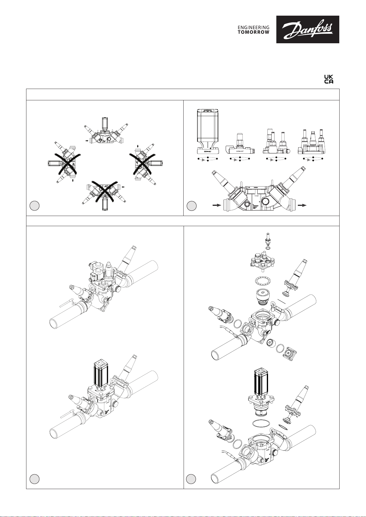
Orientation (fig. 1)
The ICF must be installed according to
fig. 1. The ICF must be installed with the
arrow in the direction of the flow).
The ICF will be delivered with all the
function modules fully assembled. The
modules can be taken out for service
or inspection and may be rotated 4 x
90° in relation to the valve body upon
installation (fig. 1b).
The ICF is designed to withstand a high
internal pressure. However, the piping
system should be designed to avoid liquid
traps and reduce the risk of hydraulic
pressure caused by thermal expansion.
It must be ensured that the ICF is protected
from pressure transients like “liquid
hammer” in the system.
Welding (fig. 2 and 3)
The ICF valve station can be welded by
using either TIG/MIG/SMAW welding (fig. 2)
or gas welding (fig. 3).
Always keep inlet and outlet protecting
caps on the valve until the valve is ready
to be installed, in order to prevent rust
formation inside the valve station.
TIG/MIG/SMAW welding
It is not necessary to remove any of the
function modules prior to TIG/MIG/SMAW
welding (fig. 2) and auxiliary cooling is not
needed at normal heat impact.
Every precaution must be taken to
minimize welding spatter.
To avoid any welding spatter entering the
valve station and to avoid heat impact
to the Teflon seat during welding, it is
recommended to open the valves slightly
(approx. 1 turn from closed position) in first
and last module (M1 and M4).
When welding is completed it is
recommended to close the 2 modules
again (M1 and M4) in order to protect the
interior of the valve until the system is
ready for operation.
Gas welding
Remove all inserts before welding (fig. 3).
Auxiliary cooling is not needed at normal
heat impact.
Every precaution must be taken to
minimize welding spatter.
After welding, clean the valve inside for
welding spatter and welding debris.
It is recommended to reinstall the modules
right after welding and to close the 2
modules again (M1 and M4) in order to
protect the interior of the valve until the
system is ready for operation.
In case the valve is not assembled
immediately make sure that rust protective
oil is applied to the inside surfaces.
Mounting of valves
- Make sure that piping into which a valve
is installed is properly supported and
aligned square and plumb to the joining
sections.
- Ensure that the finalized valve assembly
is free of any stresses from external loads.
- Use only new gaskets manufactured by
Danfoss.
- Ensure that installed valves are properly
pressure tested, leak tested, evacuated
before charging with refrigerant in
accordance with ANSI /IIAR 5, EN378-2 or
ISO 5149-2.
The enclosed valves must not be mounted
in systems where the outlet side of the
valve is open to atmosphere. The outlet
side of the valve must always be connected
to the system or properly capped off, for
example with a welded-on end plate.
Side port connections (fig. 12)
The ICF features 2 groups of 2 individual
side ports. The 2 smaller ports P1 and
P3 are intended for service devices like
service valve, gauge or sight glass, while
the bigger ports P2 and P4 can be used for
defrost drain from the evaporator when
doing defrost (typically hot gas).
P2 and P4 can be converted to side ports
similar to P1 and P3 by installing separate
accessories (see the ICF data sheet).
Surface protection and identification
The external surface is zinc-chromated to
provide corrosion protection according to
EN 12284:2003 8.13.
The Zinc-Chromatization does not cover
the welding connections. After installation
has been completed the external surface
of the valve must be protected against
corrosion with a suitable top coating.
Coverage of the ID label when painting the
ICF is recommended.
Precise identification of the ICF is made
via the ID label on each of the 4 function
modules.
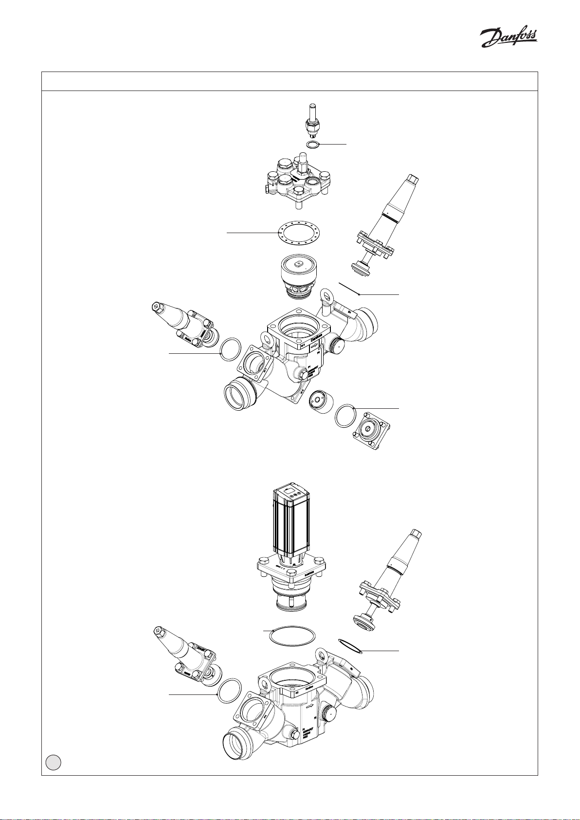
Maintenance (fig. 4)
Service
The ICF valve stations are easy to service.
Do not open the ICF while it is still under
pressure.
Upon opening and removal of the
modules:
- Check that the flat gaskets and/or
O-rings between the module
and the housing and O-rings on the
function module has not been damaged.
Replace flat gaskets and O-rings if not
intact.
A valve with a damaged o-ring/gasket
might not modulate according to the
specification.
Flat gaskets and O- are present in the
locations shown in fig. 4.
CO2 applications
When used in CO2 systems
the O-rings (see fig. 4) can swell
(grow).
At service it is recommended to replace
the actual number of used O-rings before
the modules are reinstalled in the ICF valve
body.
Assembly
Remove any dirt from the housing before
the ICF is assembled.
- Check that all channels in the ICF
are free of particles or similar debris.
If possible, apply some refrigeration oil
to ease the insertion of the modules and
to protect the O-rings.
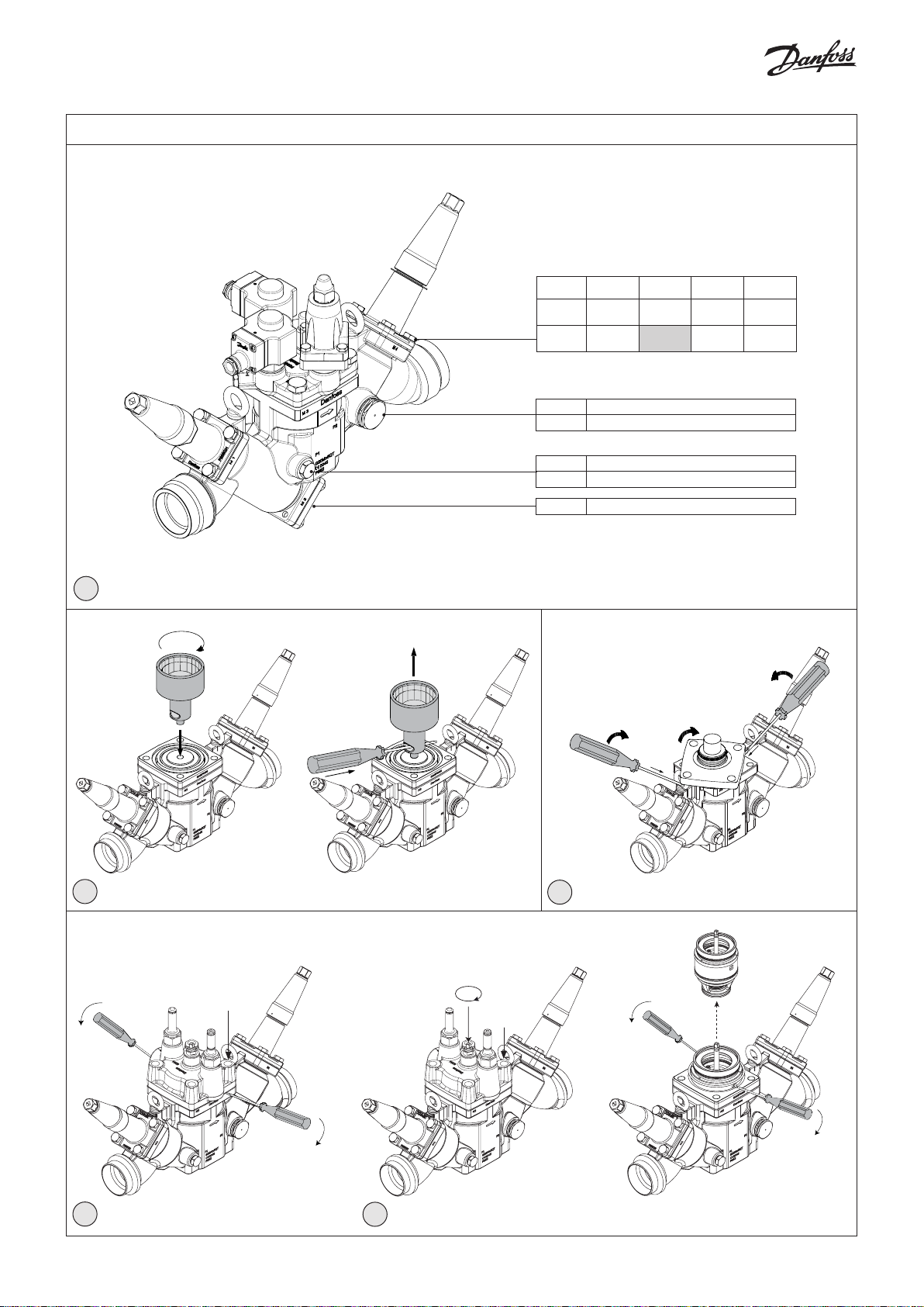
Tightening (fig. 5)
Tighten the top covers and plugs with a
torque wrench, to the values indicated in
the table (see fig. 5).
Replacing or servicing the function
module in the ICS, ICM, ICLX and ICSH
modules:
ICS/ICSH module (fig. 6)
Remove the top cover.
The function module can be lifted out
using a bolt size M6 or multi-function
tool screwed into the threaded hole of
the piston on the function module (fig.
6). Debris blocking the bolt hole will need
cleaning.
- Remove the old module.
- Oil the O-rings on the new module with
a small amount of refrigeration oil.
ICM module (fg. 7)
Remove the existing module (fig. 7):
1. After removing the 4 bolts twist the
module approx. 45° in either direction.
2. Push two screwdrivers in between the
top cover and the valve body.
3. Pull the screwdrivers upwards to release
the function module and its o-rings.
- Remove the old module.
- Oil the O-rings on the new module with
a small amount of refrigeration oil.
© Danfoss | DCS (MWA) | 2021.01
AN17198641964802-000301 | 5
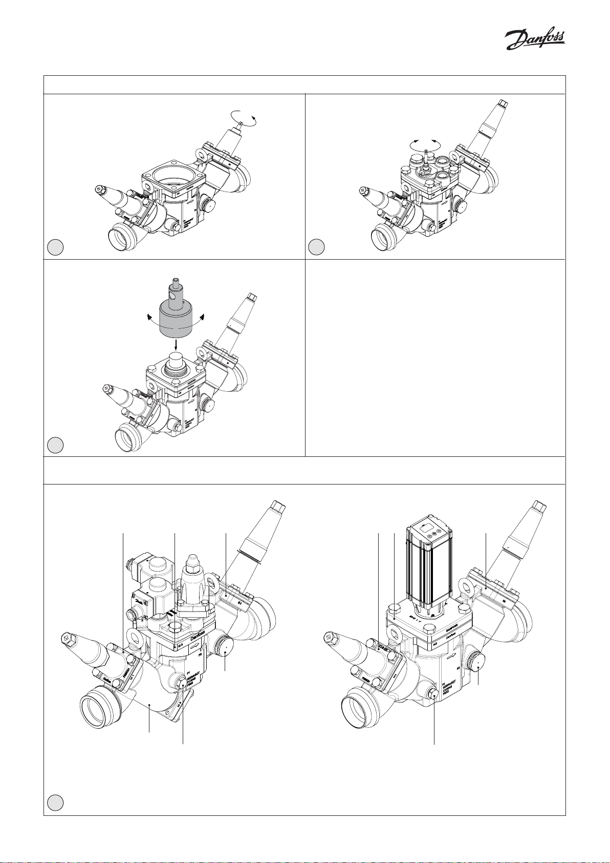
ICLX modules (fig. 8a and 8b)
Often the cover and function module can
be removed while still assembled (fig. 8a).
1. Unscrew and remove all top cover
screws.
2. Push two screwdrivers in between the
top cover and the valve body and pull
the screwdrivers downwards to
release the function module and its
o-rings.
If the internal O-rings stick to the metal
surface it is necessary to disassemble in 2
steps (fig. 8b).
1. Remove spindle sign, lock ring and lock
washer and turn the spindle downwards,
out of thread.
Remove the top cover.
2. Insert two screwdrivers into the two
grooves in the function module and
press the screwdrivers downwards to
release the function module and its
o-rings.
Upon opening and removal of the function
module:
- Check that the o-rings on the function
module has not been damaged.
A valve with a damaged o-ring might
not operate according to the
specification.
- The insert and piston assembly can
be disassembled and wear parts can be
replaced.
For detailed information please see the
installation guide for ICS, ICM, ICLX or ICSH
valves.
Backseating SVA-S or REG-SB
module (fig. 9)
To backseat turn the spindle counterclockwise until the valve is fully open.
Before remounting the cap on the modules
please ensure that the gasket is present in
the cap. Then tighten the cap with 16 Nm
(12 ft lbs).
Manual operation of
ICLX module (fig. 10)
Normal operation mode:
For the valve to operate normally under the
influence of the pilot valves the spindle of
the manual operation device needs to be
turned fully clockwise.
Manual forced opening:
To manually open the valve the spindle of
the manual operation device needs to be
turned fully counter clockwise.
Manual operation of
ICS/ICSH module (fig. 10)
Normal operation mode:
For the valve to operate normally under the
influence of the pilot valves the spindle of
the manual operation device needs to be
turned fully counter clockwise.
Manual forced opening:
To manually open the valve the spindle of
the manual operation device needs to be
turned fully clockwise.
Note:
Always pay attention to the spindle
during operation of the manual opener
1. Pay attention to the C-clip reaching the
top of the manual stem top nut (ICSH:
spacer between C-clip and manual stem
top nut) when turning the manual stem
clockwise for opening the valve.
Never use excessive torque and stop
turning when the C-clip gets in
contact with the Nut/Spacer.
2. When turning the spindle anticlockwise,
for deactivation of the manual opener, to
the top point, tighten the spindle further
anticlockwise to 8 Nm (5.9 lb/ft) torque
for back-seating.
3. Remount the cap and tighten it
clockwise to 8 Nm (5.9 lb/ft) torque.
Manual operation of
ICM module (fig. 11)
A magnetic coupling can be used to rotate
the spindle manually when the actuator
has been removed. To make use of the
manual operation, a multi-function tool
(optional) is used (see fig. 11).
Manual operation is also possible with the
actuator mounted on the valve and the
power supply connected to the actuator.
No matter if the signal connections are
wired to the actuator it will be possible to
use the manual operation function built
into the actuator electronics allowing the
motor to step in 1% increments meaning
that 100 steps will correspond to a
fully open valve. Please refer to the
separate instruction on ICAD to address the
manual function.
Use only original Danfoss parts, including
O-rings and gaskets for replacement.
Materials of new parts are certified for the
relevant refrigerant.
In cases of doubt, please contact Danfoss.
For further service / maintenance details
on the modules ICM, ICS, ICSH, ICLX,
SVA-S, REG-SB and FIA; please refer to the
individual product installation guide, which
can be downloaded from danfoss.com.
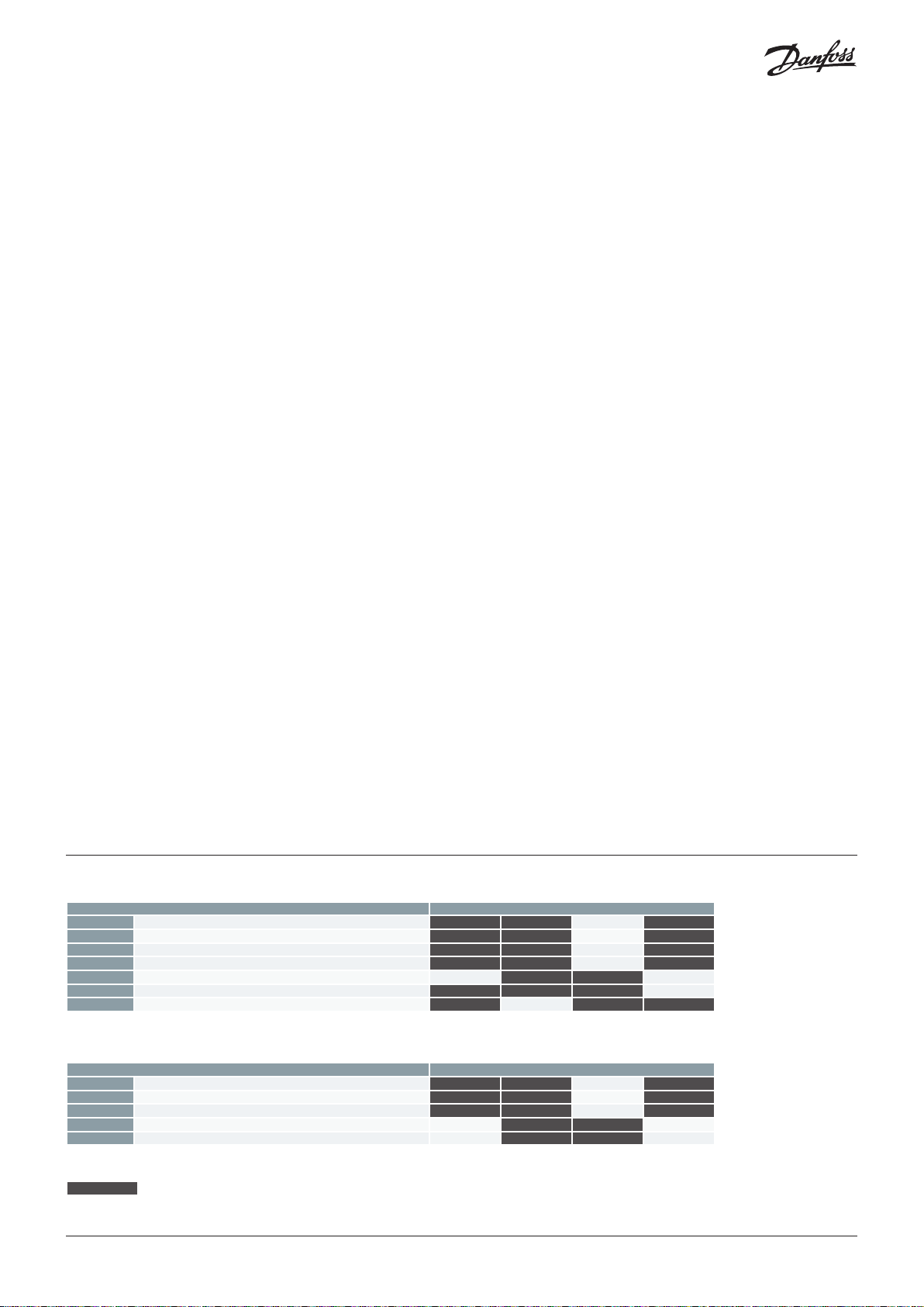
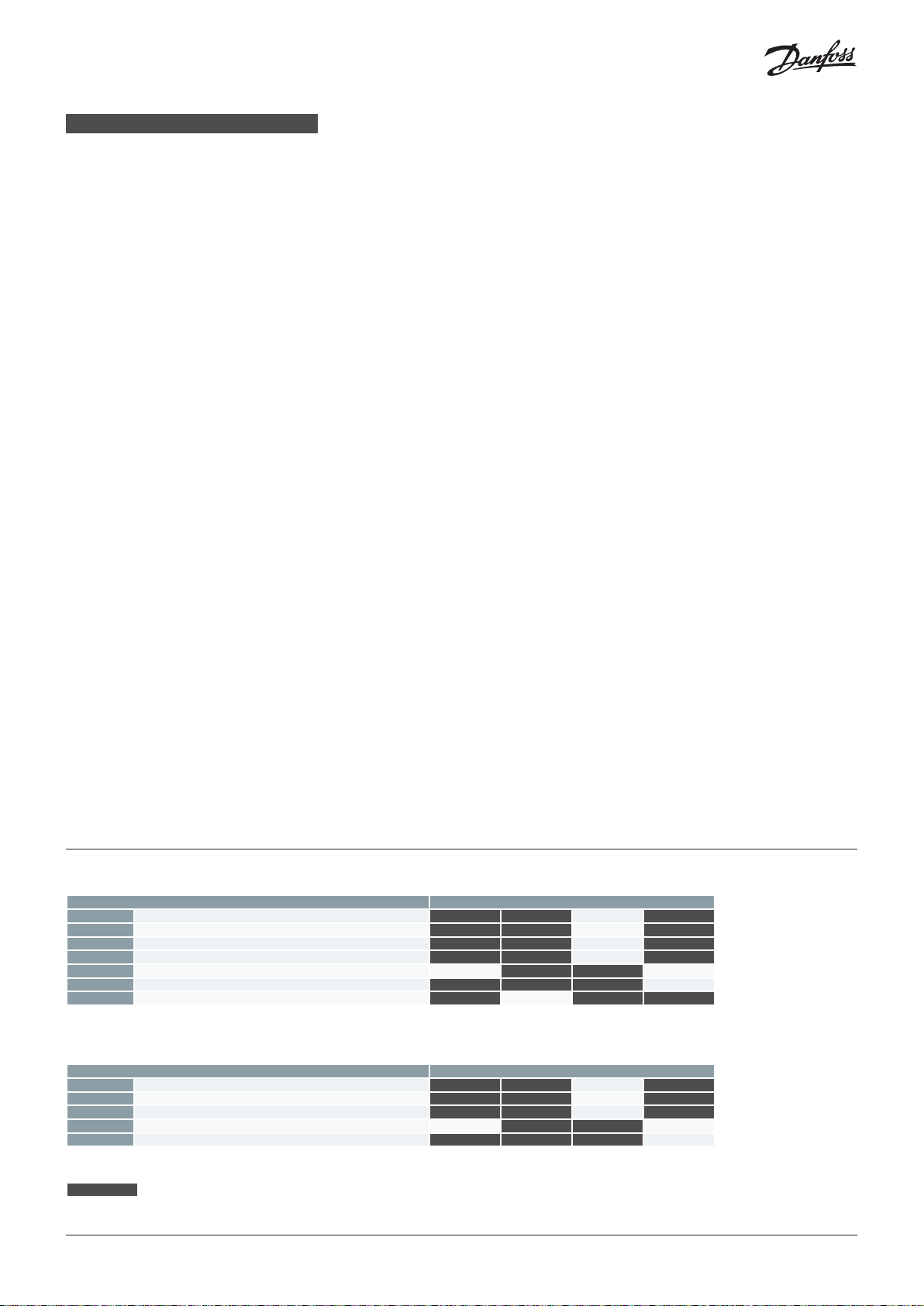
Module and side port location (fig. 12)
ICF 50-4
Function Module Type Can be installed in these locations
ICM Motor operated valve module M3
ICS Pilot operated serco valve module M3
ICSH Dual position solenoid valve module M3
ICLX Solenoid valve module M3
SVA-S Shut-off valve module M1 M4
REG-SB Regulating valve module M4
FIA Strainer module M2
P1 & P3 (P3 on the opposite side of P1): Side ports for gauge valve, sight glass, etc..
P2 & P4 (P4 on the opposite side of P2): Side ports for defrost drain or other purposes.
ICF 65-3
Function Module Type Can be installed in these locations
ICM Motor operated valve module M3
ICS Pilot operated servo valve module M3
ICLX Solenoid valve module M3
SVA-S Shut-off valve module M1 M4
REG-SB Regulating valve module M4
P1 & P3 (P3 on the opposite side of P1): Side ports for gauge valve, sight glass, etc..
P2 & P4 (P4 on the opposite side of P2): Side ports for defrost drain or other purposes.
location not possible
*) Modules are fixed
*)
*)
© Danfoss | DCS (MWA) | 2021.01
AN17198641964802-000301 | 6

DEUTSCH
Kältemittel
für alle herkömmlichen, nicht entflammbaren
Kältemittel einschließlich R717, R744 (CO2)
und nicht korrosive Gase/ Flüssigkeiten je
nach Verträglichkeit mit den Dichtwerkstoffen
Der Einsatz von brennbaren Kohlenwasserstoffen wird nicht empfohlen.
Die ICF-Ventilstation ist nur für die
Verwendung in geschlossenen Kreisen
vorgesehen. Für weitere Informationen
wenden Sie sich bitte an Danfoss.
Temperaturbereich
-60 – 120 °C / -76 – 248 °F
Druckbereich
Die ICF-Ventilstation ist ausgelegt für einen
maximal zulässigen Betriebsüberdruck von 52
bar g (754 psig).
Anwendung
Die ICF-Ventilstation kann in Saug,- Flüssigkeits-,
Heißgas- und Flüssigkeits-/Dampfleitungen
verwendet werden. Sie regelt den
Mediendurchfluss oder eine EIN/AUS-Funktion,
je nach eingebautem Funktionsmodul.
Regelbereich
Der Regelbereich ist abhängig vom gewählten
Typ und der im Ventil eingebauten Module.
Einbaulage (Abb. 1)
Die ICF-Ventilstation muss gemäß Abb. 1.
eingebaut werden. Sie ist so einzubauen,
dass der Pfeil in die Durchflussrichtung zeigt.
Die ICF-Ventilstation wird komplett montiert
mit allen Funktionsmodulen geliefert.
Die Module können zur Wartung oder
Überprüfung entnommen und bei der
Installation 4 x 90 ° auf dem Ventilgehäuse
gedreht werden (Abb. 1b).
In jedem Fall muss das Leitungssystem so
konstruiert werden, dass Flüssigkeitseinschlüsse verhindert werden und das
Risiko von hydraulischem Druck durch
Wärmeausdehnungen reduziert wird.
Stellen Sie sicher, dass die ICF-Ventilstation
vor Druckspitzen wie Flüssigkeitsschlägen in
der Anlage geschützt ist.
Schweißarbeiten (Abb. 2 und 3)
Zum Schweißen der ICF-Ventilstation kann
Wolfram- (WIG) bzw. Metall-InertgasSchweißen (MIG) bzw. Lichtbogenschweißen
mit Mantelelektrode (SMAW) (Abb. 2) oder
Gasschweißen (Abb. 3) angewendet werden.
Stellen Sie sicher, dass die Schutzkappen des
und Austritts bis zur endgültigen Installation
immer auf dem Ventil verbleiben, um
Rostbildung in der Ventilstation zu vermeiden.
WIG-/MIG-/SMAW-Schweißen
Es ist nicht erforderlich, die Funktionsmodule
vor dem WIG-/MIG-/SMAW-Schweißen
(Abb. 2) zu entfernen. Bei einer normalen
Wärmeeinwirkung kann zudem auf eine
zusätzliche Kühlung verzichtet werden.
Zum Vermeiden von Schweißspritzern müssen
alle erforderlichen Sicherheitsvorkehrungen
getroffen werden.
Damit keine Schweißspritzer in die
Ventilstation gelangen und um zu verhindern,
dass der Teflon-Sitz beim Schweißen Wärme
ausgesetzt wird, wird empfohlen, die Ventile
im ersten und letzten Modul (M1 und M4)
Ein-
etwas zu öffnen (etwa eine Drehung von der
geschlossenen Stellung aus).
Es wird empfohlen, nach Abschluss der
Schweißarbeiten die beiden Module M1
und M4 wieder zu schließen, um das Innere
des Ventils zu schützen bis die Anlage
betriebsbereit ist.
Gasschweißen
Entfernen Sie vor dem Schweißen (Abb 3) alle
Einsätze.Bei einer normalen Wärmeeinwirkung
keine zusätzliche Kühlung erforderlich.
Zum Vermeiden von Schweißspritzern müssen
alle erforderlichen Sicherheitsvorkehrungen
getroffen werden.
Reinigen Sie nach dem Schweißen das
Ventilinnere von Schweißspritzern und
-rückständen.
Es wird empfohlen, direkt nach Abschluss
der Schweißarbeiten die Module M1 und M4
wieder einzusetzen und zu schließen, um das
Innere des Ventils zu schützen bis die Anlage
betriebsbereit ist.
Falls das Ventil nicht sofort montiert wird,
streichen Sie Rostschutzöl auf die inneren
Flächen.
Ventileinbau
- Stellen Sie sicher, dass Leitungen, in denen
die ICF-Ventilstation eingebaut ist,
angemessen abgestützt sind.
- Stellen Sie sicher, dass die fertige
Ventilkonstruktion vollkommen
spannungsfrei montiert ist.
- Verwenden Sie nur neue von Danfoss
hergestellte Dichtungen.
- Stellen Sie sicher, dass die eingebauten
Ventile ordnungsgemäß einer Druck- und
Leckageprüfung unterzogen wurden und
vor der Befüllung mit Kältemittel gemäß
ANSI/IIAR 5, DIN EN 378-2 oder ISO 5149-2
evakuiert wurden.
Die ICF-Ventilstation darf nicht in Anlagen
verwendet werden, bei denen die
Austrittsseite des Ventils zur Atmosphäre
offen ist. Die Austrittsseite des Ventils muss
immer an die Anlage angeschlossen oder
ordnungsgemäß verschlossen sein, z. B. mit
einer angeschweißten Endplatte.
Seitliche Ports (Abb. 12)
Die ICF-Ventilstation verfügt über zwei Arten
von seitlichen Ports. Die zwei kleineren Ports
und P3 sind für Servicezwecke, wie
Serviceventile, Messgeräte oder Schaugläser
vorgesehen. Die größeren Ports P2 und P4
können während der Abtauung für das
Abtaukondensat aus dem Verdampfer
verwendet werden (in der Regel mit Heißgas).
P2 und P4 können durch das Installieren von
separatem Zubehör (siehe ICF-Datenblatt) zu
seitlichen Ports (wie P1 und P3) umgewandelt
werden.
Oberflächenschutz und Identifikation
Die äußere Oberfläche ist zinkchromatiert,
gemäß DIN EN 12284:2003 8.13.
Die Zinkchromatierung deckt nicht die
Schweißverbindungen ab. Nach
abgeschlossener Installation muss die
äußere Oberfläche des Ventils mit einer
geeigneten Beschichtung vor Korrosion
geschützt werden.
Beim Anstrich der ICF-Ventilstation wird
die Abdeckung der IdentifizierungsKennzeichnung empfohlen.
Die präzise Identifikation der ICFFunktionsmodule erfolgt über die
Identifizierungs-Kennzeichnung.
ist
P1
Instandhaltung (Abb. 4)
Wartung
Die ICF-Ventilstation ist einfach zu warten.
Sie darf nicht geöffnet werden, wenn sie noch
unter Druck steht.
Folgendes ist zu überprüfen, nachdem
Sie das Funktionsmodul geöffnet und
entnommen haben:
- Überprüfen Sie, ob die Flachdichtungen
und/oder O-Ringe zwischen dem
Funktionsmodul und dem Gehäuse sowie
die O-Ringe auf dem Funktionsmodul
beschädigt wurden.
Ersetzen Sie die Flachdichtungen und
O-Ringe, wenn dies der Fall ist.
Ein Funktionsmodul mit einer
beschädigten Dichtung bzw. einem
beschädigten O-Ring kann nicht
ordnungsgemäß arbeiten.
Die Flachdichtungen und O-Ringe sind in
Abb. 4 zu sehen.
CO2-Anwendungen
Beim Einsatz in CO2-Anlagen
können die O-Ringe (siehe Abb. 4)
anschwellen (wachsen).
Bei der Wartung empfiehlt es sich,
die verwendeten O-Ringe vor dem erneuten
Einbau der Funktionsmodule im ICFVentilgehäuse zu ersetzen.
Montage
Reinigen Sie das Gehäuse, bevor die ICF
zusammengebaut wird.
- Stellen Sie sicher, dass alle Kanäle in der
ICF-Ventilstation frei von Schmutz oder
Ähnlichem sind.
Tragen Sie, wenn möglich,
etwas Kältemaschinenöl auf, um den
Einsatz der Module zu erleichtern und
die O-Ringe zu schützen.
Festziehen (Abb. 5)
Ziehen Sie die Schrauben mit einem
Drehmomentschlüssel an, gemäß den
Werten, die in der Tabelle angegeben sind
(siehe Abb. 5).
Austausch oder Wartung des
Funktionsmoduls in den Modulen ICS, ICM,
ICLX und ICSH:
ICS/ICSH-Modul (Abb. 6)
Entfernen Sie den Kopfdeckel.
Das Funktionsmodul kann mithilfe einer
Schraube der Größe M6, die in das
Gewindeloch des Kolbens am
Funktionsmodul eingeschraubt wird,
herausgehoben werden (Abb. 6). Wenn
Ablagerungen das Gewindeloch blockieren,
ist eine Reinigung erforderlich.
- Entfernen Sie das alte Modul.
- Tragen Sie auf die O-Ringe des neuen
Moduls etwas Kältemaschinenöl auf.
ICM-Modul (Abb. 7)
Entfernen Sie das alte Modul (Abb. 7):
1. Entfernen Sie die vier Schrauben und
drehen Sie das Modul um ca. 45° in eine
Richtung.
2. Drücken Sie zwei Schraubendreher
zwischen die Endabdeckung und das
Ventilgehäuse.
3. Bewegen Sie die Schraubendreher nach
oben, um das Funktionsmodul und die
O-Ringe freizusetzen.
- Entfernen Sie das alte Modul.
- Tragen Sie auf die O-Ringe des neuen
Moduls etwas Kältemaschinenöl auf.
ICLX-Modul (Abb. 8a und 8b)
© Danfoss | DCS (MWA) | 2021.01
AN17198641964802-000301 | 7

DEUTSCH
Oftmals kann der Kopfdeckel zusammen mit
dem Funktionsmodul entfernt werden, ohne
den Kopfdeckel und das Funktionsmodul
einzeln zu demontieren (Abb. 8a).
1. Lösen und entfernen Sie alle Schrauben der
Abdeckung.
2. Drücken Sie zwei Schraubendreher
zwischen die Endabdeckung und das
Ventilgehäuse und bewegen Sie die
Schraubendreher nach unten, um das
Funktionsmodul und die O-Ring
freizusetzen.
Wenn die inneren O-Ringe an der Metallfläche
kleben, ist es erforderlich, das Ventil zu
demontieren (zwei Schritte, siehe Abb. 8b).
1. Entfernen Sie die Abdeckung der
Spindel, den Verschlussring und die
Sicherungsscheibe. Drehen Sie dann
die Spindel nach unten (aus dem Gewinde
heraus).
Entfernen Sie den Kopfdeckel.
2. Führen Sie zwei Schraubendreher in die
beiden Nuten des Funktionsmoduls ein
und bewegen Sie die Schraubendreher
nach unten, um das Funktionsmodul und
die O-Ringe freizusetzen.
Folgendes ist zu überprüfen, nachdem Sie das
Funktionsmodul geöffnet und entnommen
haben:
- Überprüfen Sie, ob die O-Ringe auf dem
Funktionsmodul beschädigt worden sind.
Ein Ventil mit einem beschädigten O-Ring
kann nicht ordnungsgemäß arbeiten.
- Der Einsatz und die Kolbeneinheit können
demontiert und Verschleißteile können
ausgetauscht werden.
Weitere Informationen finden Sie in der
Installationsanleitung der ICS-, ICM-, ICLX-und
ICSH-Ventile.
Rücksitzdichtung der Module SVA-S
und REG-SB (Abb. 9)
(z. B. Stopfbuchse austauschen)
Drehen Sie die Spindel gegen den
Uhrzeigersinn, bis das Ventil voll geöffnet ist.
Setzen Sie die Dichtung in die Kappe ein.
Setzen Sie dann die Kappe auf das Modul.
Ziehen Sie die Kappe mit 16 Nm (12 ft lbs) fest.
Handbedienung des ICLX-Moduls (Abb. 10)
Normaler Betriebsmodus:
Damit das Ventil unter Einfluss der Pilotventile
(Automatikbetrieb) arbeitet, muss die
Handspindel bei dem ICS-Funktionsmodul
vollständig gegen den Uhrzeigersinn gedreht
werden.
Wohingegen für das ICLX-Funktionsmodul
die
Handspindel vollständig im Uhrzeigersinn
hineingedreht sein muss.
Manuelle Ventilöffnung:
Um das ICS-Venti manuell zu öffnen,
muss die Handspindel vollständig im
Uhrzeigersinn gedreht werden. Bei dem ICLXFunktionsmodul muss die Handspindel
vollständig gegen den Uhrzeigersinn gedreht
werden.
Hinweis:
Achten Sie beim Verwenden der
Handbedienung darauf, dass die Spindel
nicht überdreht wird.
1. Sicherstellen, dass der Sprengring (C) an
der Handspindel (B) angebracht und intakt
ist. Ein neuer Sprengring ist im
Reperatursatz des Ventils enthalten.
Zum manuellen Öffnen des Ventils
drehen Sie die Handspindel im
Uhrzeigersinn max. soweit, dass der
Sprengring den Gehäusedeckel (ICSH:
Distanzstück) berührt Verwenden Sie
niemals ein zu hohes Drehmoment.
2. Zum Deaktivieren der Handbedienung
drehen Sie die Handspindel entgegen
dem Uhrzeigersinn bis zum oberen
Anschlag am Kopfdeckel. Um die
Rücksitzdichtung zu gewährleisten beenden
Sie diesen Schritt mit einem Drehmoment
von 8 Nm (5,9 lb ft).
3. Befestigen Sie die Kappe wieder und ziehen
Sie sie im Uhrzeigersinn mit 8 Nm (5,9 lb ft)
fest.
Handbedienung des ICS-/ICSH-Moduls
(Abb. 10)
Normaler Betriebsmodus:
Damit das Ventil unter Einfluss der Pilotventile
arbeitet, muss die Handspindel vollständig
gegen den Uhrzeigersinn gedreht werden.
Manuelle Ventilöffnung:
Um das Ventil manuell zu öffnen, muss die
Handspindel vollständig im Uhrzeigersinn
gedreht werden.
Handbedienung des ICM-Moduls (Abb. 11)
Wenn der Stellantrieb entfernt wurde, kann
zum manuellen Drehen der Spindel eine
magnetische Kupplung eingesetzt werden.
Für die Handbedienung kann das
Multifunktionswerkzeug verwendet werden
(siehe Abb. 11).
Eine Handbedienung ist ebenfalls mit dem
Stellantrieb am Ventil und angeschlossener
Stromversorgung am Stellantrieb möglich.
Unabhängig davon, ob die Signalanschlüsse
an den Stellantrieb angeschlossen sind, ist es
möglich, die in die Stellantriebselektronik
integrierte Handbetriebsfunktion einzusetzen.
Durch sie kann der Stellantrieb in Schritten
von 1 % bis 100%, voll geöffnet werden.
Weitere Informationen zur Handbedienung
finden Sie in der separaten ICAD-Anleitung.
Benutzen Sie für den Austausch nur
Originalteile von Danfoss, einschließlich
O-Ringe und Dichtungen.
Die Werkstoffe der neuen Komponenten sind
für die entsprechende Kältemittel zertifiziert.
Im Zweifelsfall wenden Sie sich bitte an
Danfoss.
Weitere Informationen zum Bedienen/Warten
der Module ICM, ICS, ICSH, ICLX, SVA-S, REGSB und FIA finden Sie in den jeweiligen
Installationsanleitungen, die unter danfoss.
com heruntergeladen werden können.
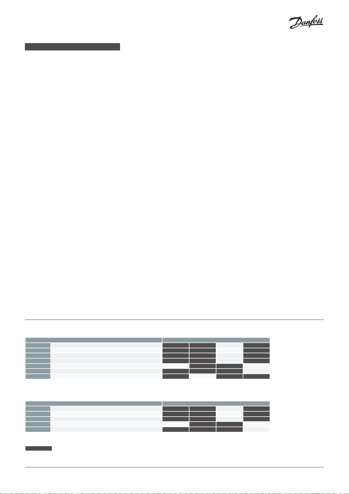
Modul und Lage der seitlichen Ports (Abb. 12)
ICF 50-4
Funktionsmodultyp Für diese Einbauorte geeignet
ICM Motorventilmodul M3
ICS ICS Hauptventilmodul M3
ICSH Doppelpositions-Magnetventilmodul M3
ICLX Magnetventilmodul M3
SVA-S Absperrventilmodul M1 M4
REG-SB Regelventilmodul M4
FIA Filtermodul M2
P1 und P3 (P3 befindet sich auf der gegenüberliegenden Seite von P1): Seitliche Ports für Serviceventile, Messgeräte, Schaugläser usw.
P2 und P4 (P4 befindet sich auf der gegenüberliegenden Seite von P2): Seitliche Ports für den Ablass bei einer Abtauung oder andere Zwecke
ICF 65-3
Funktionsmodultyp Für diese Einbauorte geeignet
ICM Motorventilmodul M3
ICS ICS Hauptventilmodul M3
ICLX Magnetventilmodul M3
SVA-S Absperrventilmodul M1 M4
REG-SB Regelventilmodul M4
P1 und P3 (P3 befindet sich auf der gegenüberliegenden Seite von P1): Seitliche Ports für Serviceventile, Messgeräte, Schaugläser usw.
P2 und P4 (P4 befindet sich auf der gegenüberliegenden Seite von P2): Seitliche Ports für den Ablass bei einer Abtauung oder andere Zwecke
Einbauort nicht möglich
*) Die Module sind fest.
*)
*)
© Danfoss | DCS (MWA) | 2021.01
AN17198641964802-000301 | 8

FRANÇAIS
Fluides frigorigènes
Convient aux fluides frigorigènes HCFC,
HFC ininflammable, R717 (ammoniac) et
R744 (CO2).
L’utilisation de stations de vannes ICF avec
des hydrocarbures inflammables n’est pas
recommandée.
L’ICF est recommandée uniquement pour
une utilisation en circuits fermés. Merci de
contacter Danfoss pour de plus amples
informations.
Plage de température
-60 – 120 °C / -76 – 248 °F
Plage de pression
L’ICF est conçue pour une pression max. de
service de 52 bar g / 754 psi g.
Application
L’ICF peut être utilisée sur les conduites
d’aspiration, de liquide, de gaz chaud et
de liquide/vapeur. L’ICF régule le débit du
fluide par modulation ou par fonction tout
ou rien, selon les modules fonctionnels
installés dans l’ICF.
Plage de régulation
Dépend du type choisi et de la combinaison
de modules installés dans la vanne.
Orientation (fig. 1)
L’ICF doit être installée conformément à la
fig. 1. L’ICF doit être installée avec la flèche
dans le sens de la circulation du fluide.
L’ICF est fournie avec tous les modules
fonctionnels entièrement assemblés.
Les modules peuvent être retirés pour
entretien ou inspection et peuvent être
tournés de 4 fois 90° par rapport au corps
de vanne lors de l’installation (fig. 1b).
L’ICF est conçue pour résister à une
pression interne élevée. Toutefois, la
tuyauterie doit être conçue pour éviter
les pièges à liquide et réduire le risque
de pression hydraulique causée par la
dilatation thermique.
Veillez à ce que l’ICF soit protégée des
variations de pression (« coups de béliers »)
au sein du circuit.
Soudage (fig. 2 et 3)
La station de vannes ICF peut être soudée
en utilisant un système de soudure type
TIG/MIG/SMAW (fig. 2) ou d’une soudure au
gaz (fig. 3).
Gardez toujours les capuchons de
protection sur l’entrée et la sortie de la
vanne jusqu’à ce qu’elle soit prête à être
installée afin d’éviter la formation de rouille
dans la station de vannes.
Soudage TIG/MIG/SMAW
Il n’est pas nécessaire de retirer l’un des
modules fonctionnels avant le soudage
TIG/MIG/SMAW (fig. 2) ; un refroidissement
auxiliaire est inutile en cas de choc
thermique normal.
Il convient de prendre toutes les
précautions nécessaires pour minimiser les
éclaboussures de soudure.
Pour éviter toute projection d’éclaboussures
de soudure dans la station de vannes et
tout choc thermique sur le siège en Téflon
pendant le soudage, il est recommandé
d’ouvrir légèrement les vannes (env. 1 tour à
partir de la position fermée) dans le premier
et le dernier module (M1 et M4).
Une fois le soudage terminé, il est
recommandé de refermer les 2 modules
(M1 et M4) afin de protéger l’intérieur de la
vanne jusqu’à ce que le système soit prêt à
fonctionner.
Soudure au gaz
Retirez tous les inserts avant le soudage
(fig. 3). Un refroidissement auxiliaire est
inutile en cas de choc thermique normal.
Il convient de prendre toutes les précautions
nécessaires pour minimiser les éclaboussures
de soudure.
Après le soudage, nettoyez l’intérieur de la
vanne pour éliminer les éclaboussures et
les débris de soudure.
Il est recommandé de réinstaller les
modules juste après le soudage et de
refermer les 2 modules (M1 et M4) afin de
protéger l’intérieur de la vanne jusqu’à ce
que le système soit prêt à fonctionner.
Si la vanne n’est pas montée immédiatement,
veillez à appliquer de l’huile de protection
contre la rouille sur les surfaces intérieures.
Montage des vannes
- Assurez-vous que la tuyauterie sur
laquelle une vanne est installée est
correctement soutenue et d’équerre par
rapport aux sections de raccord.
- Assurez-vous que l’assemblage final de
la vanne est libre de toute contrainte de
charges externes.
- Utilisez exclusivement des joints neufs
fabriqués par Danfoss.
- Assurez-vous que les vannes installées
sont soumises à des tests de pression et
d’étanchéité et sont correctement vidées
avant le chargement de fluide frigorigène
conformément à ANSI/IIAR 5, EN378-2 ou
ISO 5149-2.
Ces vannes ne doivent en aucun cas être
montées sur des circuits où le côté sortie
de la vanne serait mis à l’atmosphère.
Le côté sortie de la vanne doit
systématiquement être raccordé au circuit
ou obturé comme il se doit, par exemple à
l’aide d’une plaque d’extrémité soudée.
Ports latéraux (fig. 12)
L’ICF comprend 2 groupes de 2 ports
latéraux. Les 2 ports plus petits P1 et P3
sont destinés aux dispositifs d’entretien
comme les vannes de service, les
manomètres ou les voyants liquide, tandis
que les ports plus grands P2 et P4 peuvent
être utilisés pour la purge de l’évaporateur
lors du dégivrage (par gaz chaud en général).
Les ports P2 et P4 peuvent être convertis en
ports de service identiques à P1 et P3 en
installant des accessoires séparés (voir la
fiche technique de l’ICF).
Protection de surface et identification
La surface externe fait l’objet d’un
traitement (chromage au zinc) assurant une
protection contre la corrosion conforme à
la norme EN 12284:2003 8.13.
Le chromage au zinc ne couvre pas les
raccords à souder. Une fois l’installation
terminée, la surface externe de la vanne
doit être protégée de la corrosion à l’aide
d’un revêtement adéquat.
Il est recommandé de couvrir l’étiquette
d’identification lorsque l’on peint l’ICF.
L’étiquette d’identification sur chacun des
4 modules fonctionnels permet d’identifier
précisément l’ICF.
Maintenance (fig. 4)
Entretien
Les stations de vannes ICF sont faciles à
entretenir. N’ouvrez pas l’ICF lorsqu’elle est
encore sous pression.
Lors de l’ouverture et du retrait des modules :
- Vérifiez que les joints plats et/ou les
joints toriques situés entre le module
et le boîtier, ainsi que les joints toriques
situés sur le module fonctionnel, ne sont
pas endommagés.
Remplacez les joints plats et les joints
toriques altérés.
Une vanne dont les joints toriques ou
les joints plats sont endommagés risque
de ne pas moduler conformément à ses
spécifications.
Les joints plats et les joints toriques sont
présents aux emplacements indiqués sur
la fig. 4.
Applications au CO
Les joints toriques utilisés dans
les systèmes au CO2 (voir fig. 4)
peuvent gonfler (augmenter).
Il est donc recommandé, lors de
l’entretien, de remplacer le nombre réel de
joints toriques utilisés avant de réinstaller
les modules dans le corps de vanne ICF.
Assemblage
Avant l’assemblage de l’ICF, retirez toute
impureté présente dans le boîtier.
- Vérifiez que chaque canal de l’ICF est
exempt d’impuretés ou de débris.
Si possible, appliquez un peu d’huile de
réfrigération pour faciliter l’insertion des
modules et protéger les joints toriques.
2
Serrage (fig. 5)
Serrez les couvercles et les connecteurs
à l’aide d’une clé dynamométrique,
conformément aux valeurs indiquées dans
le tableau (fig. 5).
Remplacement ou entretien du module
fonctionnel des modules ICS, ICM, ICLX et
ICSH :
Module ICS/ICSH (fig. 6)
Retirez le couvercle.
Pour dégager le module fonctionnel,
introduisez une vis M6 ou l’outil
multifonction dans l’orifice fileté du piston
de ce même module (fig. 6). Retirez tout
débris qui obstrue l’orifice du boulon.
- Retirez l’ancien module.
- Appliquez un peu d’huile de réfrigération
sur les joints toriques du nouveau module.
© Danfoss | DCS (MWA) | 2021.01
AN17198641964802-000301 | 9

FRANÇAIS
Module ICM (fig. 7)
Retirez le module (fig. 7) :
1. Après avoir retiré les 4 boulons, faites
tourner le module d’environ 45° dans les
deux sens.
2. Insérez deux tournevis entre le couvercle
d’extrémité et le corps de vanne.
3. Faites levier à l’aide des tournevis pour
dégager le module fonctionnel et ses
joints toriques.
- Retirez l’ancien module.
- Appliquez un peu d’huile de réfrigération
sur les joints toriques du nouveau module.
Modules ICLX (fig. 8a et 8b)
Souvent, le couvercle et le module
fonctionnel peuvent être retirés tout en
étant assemblés (fig. 8a).
1. Retirez la marque de la tige, l’anneau
de blocage et la rondelle de blocage,
et tournez la tige vers le bas, pour la
dégager du filetage.
Retirez le couvercle.
2. I nsérez deux tournevis dans les rainures
du module fonctionnel et appuyez sur
les tournevis pour dégager le module
fonctionnel et ses joints toriques.
Si les joints toriques internes collent à
la surface métallique, ils doivent être
démontés en 2 étapes (fig. 8b).
1. Retirez la marque de la tige, l’anneau
de blocage et la rondelle de blocage,
et tournez la tige vers le bas, pour la
dégager du filetage.
2. Insérez deux tournevis entre le couvercle
d’extrémité et le corps de vanne et
faites levier à l’aide des tournevis pour
dégager le module fonctionnel et ses
joints toriques.
Lors de l’ouverture et du retrait du module
fonctionnel :
- Vérifiez que les joints toriques du module
fonctionnel ne sont pas endommagés.
Une vanne dont les joints toriques
sont endommagés risque de ne pas
fonctionner conformément à ses
spécifications.
- L’insert et l’ensemble piston peuvent être
démontés et les pièces d’usure remplacées.
Veuillez consulter le guide d’installation
des vannes ICS, ICM, ICLX ou ICSH pour des
informations détaillées.
Contre-siège SVA-S ou REG-SB
module (fig. 9)
Pour garantir l’étanchéité de la vanne,
tournez la tige dans le sens inverse des
aiguilles d’une montre jusqu’à ce qui la
vanne soit complètement ouverte.
Avant de remonter le capuchon sur les
modules, assurez-vous que le joint est
présent dans le capuchon. Serrez ensuite le
capuchon au couple de 16 Nm (12 lb ft).
Fonctionnement manuel des
modules ICLX (fig. 10)
Mode de fonctionnement normal :
Pour que les vannes pilotes contrôlent
normalement la vanne, la tige du dispositif
de fonctionnement manuel doit être
tournée à fond dans le sens des aiguilles
d’une montre.
Ouverture manuelle forcée :
Pour ouvrir la vanne manuellement,
tournez à fond la tige du dispositif de
fonctionnement manuel dans le sens
inverse des aiguilles d’une montre.
Fonctionnement manuel
des modules ICS/ICSH (fig. 10)
Mode de fonctionnement normal :
Pour que les vannes pilotes contrôlent
normalement la vanne, la tige du dispositif
de fonctionnement manuel doit être
tournée à fond dans le sens inverse des
aiguilles d’une montre.
Ouverture manuelle forcée :
Pour ouvrir la vanne manuellement,
tournez à fond la tige du dispositif de
fonctionnement manuel dans le sens des
aiguilles d’une montre.
Remarque :
Faites toujours attention à la tige
pendant le fonctionnement en
ouverture manuelle
1. Veillez à ce que le circlip atteigne le
sommet de l’écrou supérieur de la tige
manuelle (ICSH : entretoise entre le
circlip et l’écrou supérieur de la tige
manuelle) lors de la rotation de la tige
manuelle dans le sens des aiguilles d’une
montre pour ouvrir la vanne.
N’appliquez jamais un couple excessif
et cessez de tourner lorsque le circlip
entre en contact avec l’écrou/
l’entretoise.
2. Lors de la rotation de la tige dans le sens
inverse des aiguilles d’une montre
jusqu’à l’extrémité supérieure pour
désactiver l’ouverture manuelle,
continuez à serrer la tige dans le sens
inverse des aiguilles d’une montre au
couple de 8 Nm (5,9 lb/ft) pour assurer
l’étanchéité arrière.
3. Remontez le capuchon et serrez-le
dans le sens des aiguilles d’une montre
au couple de 8 Nm (5,9 lb/ft).
Fonctionnement manuel du
module ICM (fig. 11)
Il est possible de faire tourner la tige
manuellement à l’aide de l’outil magnétique
après le retrait du moteur ICAD. Le
fonctionnement manuel nécessite un outil
multifonction (en option) (voir fig. 11).
Le fonctionnement manuel est
également possible grâce au moteur
ICAD monté sur la vanne et raccordé à
l’alimentation électrique. Pour ce faire,
il n’est pas nécessaire de brancher les
raccordements de signal de l’ICAD. Le
système électronique de l’ICAD intègre
une fonction manuelle, laquelle permet de
faire fonctionner le moteur selon un pas
de 1 %, 100 pas correspondant donc à une
ouverture complète de la vanne. Veuillez
vous reporter aux instructions spécifiques
à l’ICAD pour ce qui est du fonctionnement
manuel.
Utilisez exclusivement des pièces de
rechange Danfoss d’origine, y compris pour
les joints et joints toriques.
Les matériaux des nouvelles pièces sont
homologués pour le fluide frigorigène
utilisé.
Merci de contacter Danfoss en cas de
doute.
Pour davantage d’informations sur la
maintenance/l’entretien des modules
ICM, ICS, ICLX, ICSH, SVA-S, REG-SB et
FIA, veuillez vous reporter au guide
d’installation de chaque produit, que vous
pouvez télécharger sur le site danfoss.com.
Module et emplacement des ports latéraux (fig. 12)
ICF 50-4
Type de module fonctionnel Peut être installé aux emplacements suivants
ICM Module vanne motorisée M3
ICS Module vanne servo-pilotée M3
ICSH Module de solénoïde à double position M3
ICLX Module électrovanne M3
SVA-S Module vanne d’arrêt M1 M4
REG-SB Module régleur M4
FIA Module filtre M2
P1 et P3 (P3 sur le côté opposé de P1) : Ports latéraux pour vannes manométriques, voyants liquide, etc.
P2 et P4 (P4 sur le côté opposé de P2) : Ports latéraux pour purge lors du dégivrage, ou autres.
ICF 65-3
Type de module fonctionnel Peut être installé aux emplacements suivants
ICM Module vanne motorisée M3
ICS Module vanne servo-pilotée M3
ICLX Module électrovanne M3
SVA-S Module vanne d’arrêt M1 M4
REG-SB Module régleur M4
P1 et P3 (P3 sur le côté opposé de P1) : Ports latéraux pour vannes manométriques, voyants liquide, etc.
P2 et P4 (P4 sur le côté opposé de P2) : Ports latéraux pour purge lors du dégivrage, ou autres.
Emplacement indisponible
*) Les modules sont fixes
*)
*)
© Danfoss | DCS (MWA) | 2021.01
AN17198641964802-000301 | 10

ESPAÑOL
Refrigerantes
Estas estaciones de válvulas son aptas para
refrigerantes HCFC, HFC no inflamables, R-717
(amoníaco) y R-744 (CO2).
Se desaconseja el uso de las estaciones de
válvulas ICF con hidrocarburos inflamables.
Se recomienda usar las estaciones de válvulas
ICF exclusivamente en circuitos cerrados. Si
desea obtener más información, póngase en
contacto con Danfoss.
Rango de temperatura
-60 – 120 °C / -76 – 248 °F.
Rango de presión
Las estaciones de válvulas ICF están
diseñadas para soportar una presión de
trabajo máx. de 52 bar g / 754 psi g.
Aplicaciones
Las estaciones de válvulas ICF se pueden
instalar en líneas de aspiración, líquido,
gas caliente y líquido/vapor. Su objetivo es
regular el caudal del medio por modulación
o función ON/OFF, dependiendo de los
módulos de función instalados en ellas.
Rango de regulación
El rango de regulación depende del tipo
elegido y la combinación de módulos
instalada en la válvula.
Orientación (fig. 1)
Las estaciones de válvulas ICF deben instalarse
de acuerdo con la fig. 1. La instalación debe
tener lugar de modo que la flecha coincida
con el sentido de flujo.
Las estaciones de válvulas ICF se suministran
con todos los módulos de función
completamente montados. Los módulos
se pueden desmontar para su revisión o
inspección y girarse 4 x 90° en relación con el
cuerpo de la válvula tras la instalación (fig. 1b).
Las estaciones de válvulas ICF están
diseñadas para soportar altas presiones
internas. Sin embargo, el sistema de tuberías
debe diseñarse de tal forma que se eviten las
acumulaciones de líquido y se reduzca el
riesgo asociado a la presión hidráulica
generada por la expansión térmica.
Debe garantizarse que la estación de válvulas
ICF en cuestión cuente con protección frente
a los fenómenos transitorios asociados a la
presión que puedan producirse en el sistema
(como el conocido “golpe de ariete”).
Soldadura (figs. 2 y 3)
Las estaciones de válvulas ICF se pueden
soldar aplicando soldadura TIG/MIG/SMAW
(fig. 2) o soldadura con gas (fig. 3).
Los tapones protectores instalados a la entrada
y la salida de la válvula no deben retirarse hasta
la instalación definitiva de la misma para impedir
la formación de óxido en el interior de la estación
de válvulas.
Soldadura TIG/MIG/SMAW
No es necesario desmontar ningún módulo
de función antes de una soldadura TIG/MIG/
SMAW (fig. 2) ni aplicar refrigeración auxiliar
(siempre que el impacto térmico se mantenga
dentro de los niveles normales).
Deben tomarse las precauciones que
correspondan para minimizar las salpicaduras
de soldadura.
A fin de evitar que las salpicaduras de
soldadura penetren en la estación de válvulas
e impedir que el asiento de teflón se vea
sometido a impactos térmicos durante la
soldadura, se recomienda abrir un poco las
válvulas (aproximadamente, 1 vuelta desde la
posición de cierre) de los módulos primero
y último (M1 y M4).
Una vez finalizada la soldadura, se recomienda
cerrar de nuevo los 2 módulos (M1 y M4)
para proteger el interior de la válvula hasta
que el sistema esté preparado para entrar en
funcionamiento.
Soldadura con gas
Desmonte todos los módulos de inserción
antes de efectuar la soldadura (fig. 3). No se
requiere refrigeración auxiliar con niveles de
impacto térmico normales.
Deben tomarse las precauciones que
correspondan para minimizar las salpicaduras
de soldadura.
Tras la soldadura, limpie el interior de la válvula
de salpicaduras y residuos de soldadura.
Se recomienda volver a instalar los módulos
inmediatamente después de la soldadura
y cerrar de nuevo los 2 módulos (M1 y M4)
para proteger el interior de la válvula hasta
que el sistema esté preparado para entrar en
funcionamiento.
Si la instalación de la válvula no puede
tener lugar inmediatamente, asegúrese de
aplicar aceite protector contra el óxido a las
superficies interiores.
Montaje de las válvulas
- Asegúrese de que las tuberías en las que
deba instalarse una válvula se encuentren
correctamente apoyadas y sean alineadas
totalmente perpendiculares a las secciones
de unión.
- Compruebe que las válvulas no soporten
tensiones ejercidas por cargas externas una
vez finalizada su instalación.
-
Use sólo juntas nuevas fabricadas por Danfoss.
- Asegúrese de que las válvulas instaladas
hayan superado las pruebas de presión
y fugas correspondientes y hayan sido
evacuadas antes de la carga de refrigerante,
según las normas ANSI/IIAR 5, EN 378-2 o
ISO 5149-2.
Las válvulas ICF no deben montarse en
sistemas en los que el lado de salida de la
válvula esté abierto a la atmósfera. El lado
de salida de una válvula debe permanecer
conectado al sistema o taponarse, por
ejemplo, empleando una tapa soldada.
Conexiones laterales (fig. 12)
Las estaciones de válvulas ICF poseen 2 grupos
de 2 puertos laterales cada uno. Los 2 puertos
más pequeños (P1 y P3) están destinados a
dispositivos de inspección (como válvulas de
servicio, manómetros o visores de líquido); los
otros dos puertos (P2 y P4) se pueden usar
como drenaje de desescarche desde el
evaporador al llevar a cabo operaciones de
desescarche (normalmente, por gas caliente).
Los puertos P2 y P4 se pueden convertir en
puertos laterales similares a los puertos P1 y
P3 por medio de la instalación de accesorios
(consulte el folleto técnico de las estaciones
de válvulas ICF).
Protección de la superficie e identificación
La superficie externa está zinc-cromada con
el fin de conseguir una protección adecuada
contra la corrosión, según la norma EN
12284:2003 8.13.
El zinc-cromado, no obstante, no protege las
conexiones para soldar. Una vez finalizada la
instalación, la superficie externa de la válvula
debe protegerse frente a la corrosión aplicando
un revestimiento protector adecuado.
Se recomienda cubrir la placa de características
antes de pintar una estación de válvulas ICF.
La identificación precisa de las estaciones de
válvulas ICF se puede llevar a cabo a partir de
las placas de características que ostentan
cada uno de los 4 módulos de función.
Mantenimiento (fig. 4)
Revisión
Las estaciones de válvulas ICF son fáciles de
revisar. No abra una estación de válvulas ICF
si está presurizada.
Tras la apertura y el desmontaje de los módulos:
- Compruebe que ni las juntas planas/juntas
tóricas situadas entre el módulo de función
y la carcasa ni las juntas tóricas del módulo
presenten daños.
Sustituya las juntas planas y las juntas
tóricas si no están intactas.
Puede que una válvula con una junta
tórica/junta dañada no module de acuerdo
con sus especificaciones.
Existen juntas planas y juntas tóricas en los
puntos indicados en la fig. 4.
Aplicaciones con CO
Cuando se usan en sistemas con
CO2, las juntas tóricas (consulte la
fig. 4) pueden inflarse (crecer).
Durante la inspección, se recomienda sustituir
todas las juntas tóricas usadas antes de volver
a instalar los módulos en la estación de
válvulas ICF.
Montaje
Elimine la suciedad que pueda haberse
acumulado en la carcasa antes de montar una
estación de válvulas ICF.
- Compruebe que ninguno de los canales
de la estación de válvulas ICF se encuentre
obstruido por partículas o residuos de otro
tipo.
Si es posible, aplique aceite refrigerante
para facilitar la inserción de los módulos
y proteger las juntas tóricas.
2
Apriete (fig. 5)
Apriete las cubiertas y tapones superiores
empleando una llave dinamométrica y
aplicando los pares de apriete indicados
en la tabla (consulte la fig. 5).
Sustitución o inspección del módulo de
función en módulos ICS, ICM, ICLX e ICSH:
Módulo ICS/ICSH (fig. 6)
Desmonte la cubierta superior.
El módulo de función se puede levantar
empleando una herramienta para pernos
de tamaño M6 o una herramienta multiusos
enroscada en el orificio roscado del pistón del
módulo de función (fig. 6). Es necesario limpiar
todos los residuos que obstruyan el orificio
del perno.
© Danfoss | DCS (MWA) | 2021.01
AN17198641964802-000301 | 11
ESPAÑOL
- Retire el módulo antiguo.
- Lubrique las juntas tóricas del módulo
nuevo con un poco de aceite de
refrigeración.
Módulo ICM (fig. 7)
Retire el módulo existente (fig. 7):
1. Después de retirar los 4 pernos, gire el
módulo unos 45° en cualquier sentido.
2. Inserte dos destornilladores entre la
cubierta superior y el cuerpo de la válvula.
3. Tire de los destornilladores hacia arriba
para liberar el módulo de función y sus
juntas tóricas.
- Retire el módulo antiguo.
- Lubrique las juntas tóricas del módulo
nuevo con un poco de aceite de refrigeración.
Módulos ICLX (figs. 8a y 8b)
A menudo, la cubierta y el módulo de función
se pueden retirar estando aún montados (fig. 8a).
1. Desmonte la cubierta del eje, el anillo de
bloqueo y la arandela de bloqueo, y gire el
eje hacia abajo para sacarlo de la rosca.
Desmonte la cubierta superior.
2. Inserte dos destornilladores en los dos surcos
del módulo de función y presiónelos hacia
abajo para liberar el módulo de función
y las juntas tóricas que lo acompañan.
Si las juntas tóricas internas permanecen
adheridas a la superficie metálica, deberá
desmontarlas en 2 pasos (fig. 8b).
1. Desmonte la cubierta del eje, el anillo de
bloqueo y la arandela de bloqueo, y gire el
eje hacia abajo para sacarlo de la rosca.
2. Inserte dos destornilladores entre la
cubierta superior y el cuerpo de la válvula,
y tire de ellos hacia abajo para liberar el
módulo de función y las juntas tóricas que
lo acompañan.
Después de abrir y retirar el módulo de función:
- Compruebe que las juntas tóricas del módulo
de función no hayan resultado dañadas.
Puede que una válvula con una junta tórica
dañada no funcione de acuerdo con sus
especificaciones.
- El módulo de función y el conjunto del
pistón se pueden desmontar para sustituir
las piezas deterioradas.
Si desea obtener información detallada,
consulte la guía de instalación de las válvulas
ICS, ICM, ICLX o ICSH.
Cierre de asiento superior de
los módulos SVA-S y REG-SB (fig. 9)
Para cerrar el asiento superior de un módulo,
gire el eje en sentido contrario a las agujas del
reloj hasta que la válvula quede
completamente abierta.
Antes de volver a montar el tapón en los
módulos, asegúrese de que la junta se encuentre
instalada. Apriete a continuación el tapón
aplicando un par de apriete de 16 N·m (12 lb·ft).
Accionamiento manual del módulo
ICLX (fig. 10)
Modo de funcionamiento normal:
Para que la válvula funcione normalmente bajo
la influencia de las válvulas piloto, gire el eje
del dispositivo de accionamiento manual en
el sentido de las agujas del reloj hasta el tope.
Apertura manual forzada:
Para abrir la válvula manualmente, gire el eje del
dispositivo de accionamiento manual en sentido
contrario a las agujas del reloj hasta el tope.
Accionamiento manual
del módulo ICS/ICSH (fig. 10)
Modo de funcionamiento normal:
Para que la válvula funcione normalmente
bajo la influencia de las válvulas piloto, gire el
eje del dispositivo de accionamiento manual
en sentido contrario a las agujas del reloj
hasta el tope.
Apertura manual forzada:
Para abrir manualmente la válvula, es preciso
girar el eje del dispositivo de accionamiento
manual en el sentido de las agujas del reloj
hasta el tope.
Nota:
Preste siempre atención al vástago
durante el uso del mecanismo de apertura
manual.
1. Compruebe que el anillo de retención
alcance el extremo superior del separador
entre el anillo de retención y la tuerca
superior del vástago manual al girar el
vástago manual en el sentido de las agujas
del reloj para abrir la válvula.
No ejerza demasiada fuerza y deje de
girar cuando el anillo de retención entre
en contacto con el separador.
2. Al girar el vástago en sentido contrario a las
agujas del reloj hasta el extremo superior
para desactivar el mecanismo de apertura
manual, continúe apretando el vástago
en el mismo sentido hasta alcanzar un par
de apriete de 8 Nm (5,9 lb ft) para asentarlo
contra dicho extremo.
3. Vuelva a colocar el tapón y apriételo en el
sentido de las agujas del reloj hasta alcanzar
un par de apriete de 8 Nm (5,9 lb ft).
Accionamiento manual
del módulo ICM (fig. 11)
Puede emplearse un acoplamiento
magnético para girar el vástago manualmente
si se ha desmontado el actuador. Para el
modo de accionamiento manual, se necesita
una herramienta multiusos opcional (fig. 11).
El accionamiento manual también puede
llevarse a cabo con el actuador montado en la
válvula y la alimentación eléctrica conectada
al actuador. Independientemente de si los
cables de señal están conectados o no al
actuador, es posible utilizar la función de
accionamiento manual integrada en la
electrónica del mismo, que permite desplazar
el motor en pasos de un 1 % (100 pasos
corresponden, por tanto, a la apertura total
de la válvula). Consulte las instrucciones de
los actuadores ICAD si desea obtener más
información acerca de la función de
accionamiento manual.
Use exclusivamente piezas de repuesto
originales de Danfoss, incluidas las juntas
tóricas y las juntas planas para sustitución.
Los materiales con los que se fabrican las
piezas poseen las debidas homologaciones
para el refrigerante correspondiente.
En caso de duda, póngase en contacto con
Danfoss.
Si desea obtener más información acerca de
la inspección/el mantenimiento de los
módulos ICM, ICS, ICLX, ICSH, SVA-S, REG-SB o
FIA, consulte la guía de instalación del
producto correspondiente, disponible para su
descarga en danfoss.com.
Ubicación de los módulos y puertos laterales (fig. 12)
ICF 50-4
Tipo de módulo de función Se pueden instalar en estas posiciones
ICM Módulo de válvula motorizada M3
ICS Módulo de válvula servoaccionada pilotada M3
ICSH Módulo de válvula de solenoide de doble posición M3
ICLX Módulo de válvula solenoide M3
SVA-S Módulo de válvula de cierre M1 M4
REG-SB Módulo de válvula de regulación M4
FIA Módulo de filtro M2
P1 y P3 (P3 en el lado opuesto a P1): Puertos laterales para manómetros, visores de líquido, etc.
P2 y P4 (P4 en el lado opuesto a P2): Puertos laterales para drenaje de desescarche y otros fines.
ICF 65-3
Tipo de módulo de función Se pueden instalar en estas posiciones
ICM Módulo de válvula motorizada M3
ICS Módulo de válvula servoaccionada pilotada M3
ICLX Módulo de válvula solenoide M3
SVA-S Módulo de válvula de cierre M1 M4
REG-SB Módulo de válvula de regulación M4
P1 y P3 (P3 en el lado opuesto a P1): Puertos laterales para manómetros, visores de líquido, etc.
P2 y P4 (P4 en el lado opuesto a P2): Puertos laterales para drenaje de desescarche y otros fines.
posición no válida
*) Los módulos son fijos.
*)
*)
© Danfoss | DCS (MWA) | 2021.01
AN17198641964802-000301 | 12
PORTUGUÊS
Refrigerantes
Aplicável a HCFC, HFC não inflamável,
R717 (amoníaco) e R744 (CO2).
O uso de bloco de válvulas ICF com
hidrocarbonetos inflamáveis não é
recomendado.
A ICF é recomendada apenas para uso
em circuitos fechados. Para obter mais
informações, entre em contato com a Danfoss.
Faixa de temperatura
-60 – 120 °C / -76 – 248 °F
Faixa de pressão
A ICF foi projetada para uma pressão de
trabalho máx. de 52 bar g / 754 psi g.
Aplicação
A ICF pode ser usada em linhas de sucção,
de líquido, de gás quente e de líquido/
vapor. A ICF regula o fluxo do meio pela
modulação ou função liga/desliga,
dependendo dos módulos de função
instalados na ICF.
Faixa de regulagem
Depende do tipo escolhido e combinação
de módulos instalados na válvula.
Orientação (fig. 1)
A ICF deve ser instalada de acordo com a
fig. 1. A ICF deve ser instalada com a seta
no sentido do fluxo.
A ICF será entregue com todos os módulos
de função totalmente montados. Os
módulos podem ser retirados para
manutenção ou inspeção e podem ser
girados 4 x 90° em relação ao corpo da
válvula após a instalação (fig 1b).
A ICF foi projetada suportar uma elevada
pressão interna. No entanto, o sistema de
tubulação deve ser projetado para evitar
enclausuramento de líquido e reduzir o
risco de pressão hidráulica provocada pela
expansão térmica.
Deve-se assegurar que a ICF fique
protegida contra transitórios de pressão no
sistema, como os “golpes de aríete”.
Soldagem (fig. 2 e 3)
O bloco de válvula ICF pode ser soldado
utilizando soldagem TIG/MIG/SMAW (fig. 2)
ou soldagem a gás (fig. 3).
Mantenha sempre as tampas de proteção
da entrada e da saída do bloco de válvulas
até que ele esteja pronto para ser instalado,
para evitar a formação de ferrugem no
interior do bloco de válvulas.
Soldagem TIG/MIG/SMAW
Não é necessário remover qualquer um
dos módulos de função antes da soldagem
TIG/MIG/SMAW (fig. 2) e não é necessária
a refrigeração auxiliar no caso de um
aquecimento normal na região.
Todas as precauções devem ser tomadas
para minimizar respingos de solda.
Para evitar que quaisquer respingos de
solda entrem no bloco de válvulas e para
evitar o impacto de calor no assento de
Teflon durante a soldagem, recomenda-se
abrir ligeiramente (aprox. 1 giro da posição
fechada) o primeiro e último módulo (M1
e M4).
Quando a soldagem for concluída,
recomenda-se fechar os 2 módulos
novamente (M1 e M4) para proteger
o interior da válvula até que o sistema
esteja pronto para funcionar.
Soldagem a gás
Remova todos os elementos antes da
soldagem (fig. 3). A refrigeração auxiliar não
é necessária no caso de um aquecimento
normal na região.
Todas as precauções devem ser tomadas
para minimizar respingos de solda.
Após a soldagem, limpe os respingos e
resíduos de solda dentro da válvula.
Recomenda-se reinstalar os módulos
imediatamente após a soldagem e fechar
os 2 módulos novamente (M1 e M4) para
proteger o interior da válvula até que o
sistema esteja pronto para funcionar.
Se a válvula não for montada
imediatamente, certifique-se de que seja
aplicado nas superfícies internas um óleo
protetor contra ferrugem.
Montagem da válvulas
- Certifique-se de que a tubulação em
que a válvula será instalada esteja
devidamente apoiada e alinhada de
forma simétrica às seções de união.
- Certifique-se de que a montagem final
esteja isenta de quaisquer tensões
causadas por cargas externas.
- Utilize apenas juntas novas fabricadas
pela Danfoss.
- Certifique-se de que as válvulas
instaladas sejam devidamente testadas
relativamente a pressão e a vazamentos
e que sejam evacuadas antes do
carregamento com refrigerante de acordo
com ANSI/IIAR 5, EN378-2 ou ISO 5149-2.
As válvulas não podem ser montadas em
sistemas onde o lado de saída da válvula
esteja aberto para a atmosfera. O lado de
saída da válvula deve sempre estar conectado
ao sistema ou fechado de forma apropriada,
por exemplo soldando uma tampa.
Conexões da porta lateral (fig. 12)
A ICF apresenta 2 grupos de 2 portas
individuais laterais. As 2 portas menores P1 e
P3 destinam-se a dispositivos de assistência
como válvula de serviço, manômetro ou
visor, enquanto que as portas maiores P2 e
P4 podem ser utilizadas para drenagem do
evaporador ao descongelar (tipicamente
degelo à gás quente).
P2 e P4 podem ser convertidas para portas
laterais semelhantes a P1 e P3, instalando
acessórios separados (consulte a ficha
técnica da ICF).
Identificação e proteção de superfície
A superfície externa revestida com cromato
de zinco fornece proteção contra corrosão
conforme a EN 12284:2003 8.13.
A proteção com cormato de zinco não
abrange as conexões de solda. Após a
instalação ter sido concluída, a superfície
externa da válvula deve ser protegida
contra corrosão com um revestimento
adequado.
Recomenda-se a cobertura da etiqueta de
identificação quando a ICF for pintada.
A identificação precisa da ICF é feita através
da etiqueta de ID em cada um dos 4
módulos de função.
Manutenção (fig. 4)
Assitência técnica
Os blocos de válvulas ICF são de fácil
manutenção. Não abra a ICF enquanto
estiver sob pressão.
Ao abrir e remover os módulos:
- Verifique se as juntas planas e/ou os
o-rings entre o módulo de função e
a carcaça e os o-rings no módulo de
função não foram danificados.
Substitua as juntas planas e os o-rings se
não estiverem intactos.
Uma válvula com junta / o-ring
danificados pode não operar de acordo
com a especificação.
As juntas planas e o-rings estão
presentes nas posições mostradas na fig. 4.
Aplicações com CO
Quando usados em sistemas com
CO2, os o-rings (ver fig. 4a e 4b)
podem dilatar (aumentar).
Na assistência técnica,
recomenda-se substituir o número atual de
o-rings usados antes que os módulos
sejam reinstalados no corpo do bloco ICF.
Montagem
Remova qualquer sujeira da carcaça antes
de proceder à montagem da ICF.
- Verifique se todos os canais na ICF
estão livres de partículas ou resíduos
semelhantes.
Se possível, aplique um pouco de óleo
de refrigeração para facilitar a inserção
dos módulos e para proteger os o-rings.
2
Aperto (fig. 5)
Aperte as tampas e plugues com uma
chave de torque, nos valores indicados na
tabela (ver fig. 5).
Substituição ou manutenção dos
módulos de função nos módulos ICS,
ICM, ICLX e ICSH:
Módulo ICS/ICSH (fig. 6)
Retire a tampa.
O módulo de função pode ser removido
usando um parafuso tamanho M6 ou uma
ferramenta multifuncional parafusada no
orifício roscado do pistão do módulo de
função (fig. 6). É necessário limpar
quaisquer resíduos que estejam
bloqueando o orifício roscado.
- Remova o módulo antigo.
- Lubrifique os o-rings do novo módulo
com uma pequena quantidade de óleo
de refrigeração.
Módulo ICM (fg. 7)
Remova o módulo atual (fig. 7):
1. Após remover os 4 parafusos, gire
o módulo aproximadamente 45° em
qualquer direção.
2. Insira duas chaves de fendas entre
a tampa e o corpo da válvula.
3. Puxe as chaves de fendas para cima para
liberar o módulo de função e os
respectivos o-rings.
© Danfoss | DCS (MWA) | 2021.01
AN17198641964802-000301 | 13
PORTUGUÊS
- Remova o módulo antigo.
- Lubrifique os o-rings do novo módulo
com uma pequena quantidade de óleo
de refrigeração.
Módulo ICLX (fig. 8a e 8b)
Muitas vezes a tampa e o módulo de
função podem ser removidos ainda
montados (fig. 8A).
1. Remova o sinal do eixo, anel de trava
e arruela de pressão e gire o eixo para
baixo, fora da rosca.
Retire a tampa.
2. insira duas chaves de fendas entre a
tampa e o corpo da válvula e puxe as
chaves de fenda para baixo para liberar
o módulo de função e os seus o-rings.
Se os o-rings internos estiverem presos à
superfície de metal, é necessário
desmontar em 2 etapas (fig. 8B).
1. Remova a etiqueta metálica do eixo, anel
de trava e arruela de pressão e gire o eixo
para baixo, fora da rosca.
2. insira duas chaves de fendas entre a
tampa e o corpo da válvula e puxe as
chaves de fenda para baixo para liberar o
módulo de função e os respectivos
o-rings.
Ao abrir e remover o módulo de função:
- Verifique se os o-rings no módulo de
função não foram danificados.
Uma válvula com o-rings danificados
pode não operar de acordo com a
especificação.
- O conjunto do inserto e do pistão
podem ser desmontados e as peças
desgastadas substituídas.
Para informações detalhadas, consulte o guia
de instalação para válvulas ICS, ICM, ICLX ou
ICSH.
Contra-vedação do módulo
SVA-S ou REG-SB (fig. 9)
Para realizar a contra-vedação, gire o eixo
no sentido anti-horário até a válvula abrir
totalmente.
Antes de montar novamente a tampa (cap)
nos módulos, certifique-se de que a gaxeta
está presente na tampa. Em seguida,
aperte a tampa com 16 Nm (12 pés lbs).
Operação manual do módulo
ICLX (fig. 10)
Modo de operação normal:
Para que a válvula opere normalmente sob
a influência das válvulas piloto, o operador
manual manual precisa ser girado
completamente no sentido horário.
Abertura manual forçada:
Para abrir manualmente a válvula, o eixo
do operador manual precisa ser girado
completamente no sentido anti-horário.
Operação manual do módulo
ICS/ICSH (fig. 10)
Modo de operação normal:
Para que a válvula opere normalmente sob
a influência das válvulas piloto, o eixo do
dispositivo de operação manual precisa
ser girado completamente no sentido
anti-horário.
Abertura manual forçada:
Para abrir manualmente a válvula, o eixo do
dispositivo de operação manual precisa ser
girado completamente no sentido horário.
Observação:
Preste atenção na haste durante
abertura manual
1. Preste atenção na trava que alcança a
parte superior da porca instalada na
base manual (ICSH: espaçador entre a
trava e a porca) ao girar no sentido
horário para abrir a válvula.
Nunca utilize torque excessivo e pare
de girar quando a trava entrar contato
com uma poca/espaçador.
2. Ao girar a haste no sentido anti-horário,
para desativação da operação manual,
para o ponto superior, aperte-o no
sentido anti-horário com um torque de
8 Nm (5,9 lb/ft) para o assento posterior.
3. Remonte a tampa e aperte-a, no sentido
horário, com um torque de
8 Nm (5.9 lb/ft).
Operação manual do módulos
ICM (fig. 11)
Pode ser utilizado um acoplamento
magnético para girar o eixo manualmente
quando o atuador tiver sido removido. Para
executar a operação manual, é utilizada
uma ferramenta multifuncional (opcional)
(consulte fig. 11).
A operação manual também é possível
com o atuador montado na válvula e com
a fonte de alimentação conectada ao
atuador. Independentemente de as
conexões de sinal estarem ligadas ao
atuador ou não, é possível usar a função de
operação manual embutida na eletrônica
do atuador, permitindo ao motor ter
incrementos de 1%, o que significa que
100 passos corresponderão a uma válvula
totalmente aberta. Consulte as instruções
individuais do ICAD para obter informações
relativas à função manual.
Use apenas peças originais Danfoss,
incluindo o-rings e juntas para substituição.
Os materiais das peças novas estão
certificados para o refrigerante relevante.
Em caso de dúvida, entre em contato com
a Danfoss
Para obter mais detalhes sobre o serviço/
manutenção de módulos ICM, ICS, ICLX,
ICSH, SVA-S, REG-SB e FIA, consulte o guia
de instalação individual do produto, que
pode ser baixado em danfoss.com.
Posição de módulo e de porta lateral (fig. 12)
ICF 50-4
Tipo de módulo de função Pode ser instalado nesta posições
ICM Módulo de válvula operada por motor M3
ICS Módulo de válvula servo operada por piloto M3
ICSH Módulo de válvula solenóide de posição dupla M3
ICLX Módulo de válvula solenoide M3
SVA-S Módulo de válvula de bloqueio M1 M4
REG-SB Módulo de válvula de regulagem M4
FIA Módulo de filtro M2
P1 e P3 (P3 no lado oposto ao P1): Portas laterais para válvula para manômetro, visor, etc.
P2 e P4 (P4 no lado oposto ao P2): Portas laterais para drenagem de degelo ou outros fins.
ICF 65-3
Tipo de módulo de função Pode ser instalado nesta posições
ICM Módulo de válvula operada por motor M3
ICS Módulo de válvula servo operada por piloto M3
ICLX Módulo de válvula solenoide M3
SVA-S Módulo de válvula de bloqueio M1 M4
REG-SB Módulo de válvula de regulagem M4
P1 e P3 (P3 no lado oposto ao P1): Portas laterais para válvula para manômetro, visor, etc.
P2 e P4 (P4 no lado oposto ao P2): Portas laterais para drenagem de degelo ou outros fins.
posição impossível
*) Os módulos são fixos
*)
*)
© Danfoss | DCS (MWA) | 2021.01
AN17198641964802-000301 | 14

POLSKI
Czynniki chłodnicze
Można stosować do czynników chłodniczych:
HCFC, niepalnych czynników HFC, R717
(amoniak) i R744 (CO2).
Nie zaleca się stosowania zaworów blokowych
ICF z łatwopalnymi węglowodorami.
Zawory zaleca się stosować wyłącznie
w obiegach
więcej informacji, należy się skontaktować
z firmą Danfoss.
Zakres temperatur
-60 – 120 °C / -76 – 248 °F
zamkniętych. Aby uzyskać
roboczych (rys. 2), a podczas spawania
dodatkowe chłodzenie nie jest wymagane.
Należy podjąć wszelkie możliwe środki
ostrożności w celu zminimalizowania
odprysków spawalniczych.
Aby w trakcie spawania uniknąć
przedostawania się okruchów
spawalniczych do korpusu zaworu oraz
zapobiec przegrzaniu uszczelnienia
teflonowego, zaleca się w pierwszym i
ostatnim module (M1 i M4) otworzyć zawory
tylko częściowo (o około 1 obrót od pozycji
zamknięcia).
Zaleca się, aby po zakończeniu spawania
ponownie zamknąć te 2 moduły (M1 i M4)
w celu ochrony wnętrza zaworu do
momentu rozruchu instalacji.
Zabezpieczenie powierzchni i identyfikacja
Zewnętrzna powłoka chromowo-cynkowa,
zapewnia ochronę przed korozją zgodnie
z normą EN 12284:2003 8.13.
Powłoka chromowo-cynkowa nie pokrywa
przyłączy do spawania. Po zakończeniu
montażu należy zabezpieczyć zewnętrzną
powierzchnię zaworu przed korozją,
stosując odpowiednią powłokę ochronną.
Podczas malowania zaworu blokowego
ICF zaleca się zakrycie oznaczenia
identyfikacyjnego.
Dokładną identyfikację zaworu blokowego
ICF umożliwiają znaki identyfikacyjne
umieszczone na każdym z 4 modułów
roboczych.
Zakres ciśnień
Maksymalne ciśnienie robocze zaworu
blokowego ICF wynosi 52 bar g / 754 psi g.
Zastosowanie
Zawory blokowe ICF mogą być stosowane
w rurociągach ssawnych par suchych lub
mokrych, zasilania cieczą lub gorącymi
parami. Zawór blokowy ICF reguluje przepływ
czynnika chłodniczego, przez regulację ciągłą
lub zamknij/otwórz, w zależności od
zamontowanych modułów roboczych.
Zakres regulacji
Zależy od wybranego typu i kombinacji
modułów roboczych zamontowanych
w zaworze blokowym.
Ustawienie (rys. 1)
Zawór blokowy ICF należy zamontować
zgodnie z rys. 1. Zawór blokowy ICF należy
zamontować tak, by strzałka wskazywała
kierunek przepływu.
Zawór blokowy ICF jest dostarczany
z zmontowanymi wszystkimi modułami
roboczymi. Moduły można zdemontować
do sprawdzenia lub serwisu, mogą zostać
obrócone podczas montażu o 4 x 90°
względem korpusu zaworu (rys. 1 b).
Zawór blokowy ICF została zaprojektowany
tak aby wytrzymał wysokie ciśnienie
wewnętrzne. Układ rurociągów powinien
jednak być zaprojektowany tak, aby uniknąć
zamkniętych przestrzeni cieczowych
i zmniejszyć ryzyko wzrostu ciśnienia
wynikającego z rozszerzalności cieplnej cieczy.
Wykonanie instalacji powinno zapewnić
zabezpieczenie zaworu blokowego ICF
przed impulsami wysokiego ciśnienia
wynikającymi z uderzeń hydraulicznych.
Spawanie (rys. 2 i 3)
Zawór blokowy ICF może być spawany
metodą TIG/migomatem/metodą SMAW
(rys. 2) lub metodą spawania gazowego
(rys. 3).
Aby zapobiec powstawaniu rdzy wewnątrz
stacji zaworowej, kołpaki ochronne wlotu i
wylotu powinny przez cały czas znajdować
się na zaworze aż do chwili przystąpienia
do jego montażu.
Spawanie metodą TIG/migomatem/
metodą SMAW
Przed przystąpieniem do spawania metodą
TIG/migomatem/metodą SMAW nie ma
potrzeby usuwania żadnego z modułów
Spawanie gazowe
Przed spawaniem należy wyjąć wszystkie
elementy robocze (rys. 3). Podczas
spawania dodatkowe chłodzenie nie jest
wymagane.
Należy podjąć wszelkie możliwe środki
ostrożności w celu zminimalizowania
odprysków spawalniczych.
Po spawaniu należy oczyścić wnętrze
zaworu z odprysków i okruchów
spawalniczych.
Zaleca się, aby niezwłocznie po zakończeniu
spawania ponownie zainstalować moduły
oraz ponownie zamknąć 2 moduły
(M1 i M4) w celu ochrony wnętrza zaworu
do momentu rozruchu instalacji.
Jeśli zawór nie będzie montowany od razu,
należy posmarować jego wewnętrzne
powierzchnie olejem zabezpieczającym
przed korozją.
Montaż zaworów
- Należy zwrócić uwagę aby rury, do których
montowany jest zawór, były odpowiednio
podparte i ustawione do wykonania
właściwego połączenia.
- Sprawdzić, czy na zamontowany zawór
blokowy nie działają naprężenia
wywołane przez obciążenia zewnętrzne.
- Używać wyłącznie nowych uszczelek
produkowanych przez firmę Danfoss.
- Zamontowane zawory należy poddać
próbie ciśnieniowej, badaniu szczelności
oraz opróżnić przed napełnianiem
czynnikiem chłodniczym zgodnie z
normą ANSI /IIAR 5, EN378-2 lub ISO
5149-2.
Zaworów nie należy montować w instalacjach,
w których wylot zaworu jest otwarty do
atmosfery. Wylot zaworu musi być zawsze
podłączony do instalacji lub należycie
zaślepiony, np. przyspawaną dennicą.
Przyłącza pomocnicze (rys. 12)
Zawór blokowy ICF zawiera dwa typy, po
dwa pojedyncze przyłącza pomocniczych.
Dwa mniejsze przyłącza boczne P1 i P3 są
przeznaczone do urządzeń serwisowych,
takich jak zawór serwisowy, manometr lub
wziernik. Natomiast, większe przyłącza P2
i P4 mogą być przykładowo wykorzystywane
do podłączenia spływu cieczy z odszraniania
(zwykle za pomocą gorącego gazu).
Przyłącza P2 i P4 można zmodyfikować
do wielkości jak P1 i P3 przez zainstalowanie
odpowiednich akcesoriów (patrz karta
katalogowa stacji zaworowej ICF).
Serwis (rys. 4)
Obsługa
Serwisowanie zaworu blokowego ICF
jest łatwe. Nie otwierać zaworu ICF,
pod ciśnieniem.
Po otwarciu stacji i wymontowaniu modułów:
- Sprawdzić, czy uszczelki płaskie i/lub
o-ringi między modułem roboczym
a korpusem oraz pierścienie o-ring na
module roboczym nie są uszkodzone.
Jeśli uszczelki płaskie i pierścienie o-ring
są naruszone, wymienić je.
Zawór z uszkodzonym pierścieniem
o-ring/uszczelką może nie pracować
zgodnie z przeznaczeniem.
Uszczelki płaskie i pierścienie o-ring
znajdują się w miejscu pokazanym na rys. 4.
Zastosowanie z CO
W przypadku stosowania
w instalacjach obiegu CO2
pierścienie o-ring (rys. 4) mogą
pęcznieć (zwiększać objętość).
Podczas prac serwisowych zaleca się
wymianę wszystkich używanych pierścieni
o-ring przed ponownym zamontowaniem
modułów na korpusie zaworu ICF.
Montaż
Przed zmontowaniem zaworu ICF oczyścić
dokładnie korpus.
- Sprawdzić czystość i przelotowość
kanałów w zaworze ICF. Usunąć cząstki
stałe lub inne zanieczyszczenia.
Zastosować niewielką ilość oleju
chłodniczego, aby ułatwić montaż
modułów i zabezpieczyć pierścienie o-ring.
2
Dokręcenie (rys. 5)
Dokręcić górną pokrywę i korki kluczem
dynamometrycznym, momentem
podanym w tabeli (rys. 5).
Wymiana lub naprawa elementów
roboczych w modułach ICS, ICM, ICLX i
ICSH:
Moduł ICS/ICSH (rys. 6)
Zdjąć górną pokrywę.
Element roboczy można wyjąć za pomocą
śruby M6 lub narzędzia wielofunkcyjnego
wkręconego w gwintowany otwór w tłoku
modułu (rys. 6). Zanieczyszczenia blokujące
otwór w tłoku należy usunąć.
- Wymontować stary moduł roboczy.
- Posmarować o-ringi nowego modułu
niewielką ilością oleju chłodniczego.
© Danfoss | DCS (MWA) | 2021.01
AN17198641964802-000301 | 15

POLSKI
Moduł ICM (rys. 7)
Wymontować moduł roboczy (rys. 7):
1. Po wykręceniu 4 śrub, przekręcić moduł
o ok. 45° w dowolnym kierunku.
2. Włożyć dwa śrubokręty pomiędzy górną
pokrywę a korpus zaworu.
3. Pociągnąć śrubokręty w górę, aby zwolnić
moduł roboczy i jego pierścień o-ring.
- Wymontować stary moduł roboczy.
- Posmarować o-ringi nowego modułu
niewielką ilością oleju chłodniczego.
Moduły ICLX (rys. 8a i 8b)
Pokrywę i moduł roboczy można
wymontować, gdy są połączone - w całości.
(rys. 8a).
1. Zdjąć oznaczenie wrzeciona, pierścień
ustalający i podkładkę zabezpieczającą,
a następnie wykręcić wrzeciono w dół
z części gwintowanej.
Zdjąć górną pokrywę.
2. Włożyć dwa śrubokręty w dwa rowki
w module roboczym i pchnąć śrubokręty
w dół, aby wyjąć moduł roboczy wraz
z pierścieniami o-ring.
Jeżeli wewnętrzny pierścień o-ring
przylega do powierzchni metalowej,
konieczne jest zastosowanie procedury
dwuetapowej (rys. 8b).
1. Zdjąć oznaczenie wrzeciona, pierścień
ustalający i podkładkę zabezpieczającą,
a następnie wykręcić wrzeciono w dół
z części gwintowanej.
2. Włożyć dwa śrubokręty pomiędzy górną
pokrywę a korpus zaworu i pchnąć je w dół,
aby wyjąć moduł roboczy i pierścień o-ring.
Po demontażu modułu roboczego:
- Sprawdzić, czy pierścienie o-ring modułu
roboczego nie uległy uszkodzeniu.
Zawór z uszkodzonym pierścieniem
o-ring może nie działać zgodnie
z przeznaczeniem.
- Element roboczy można rozmontować
i wymienić zużyte części.
Szczegółowe informacje znajdują się
w instrukcji montażu zaworów ICS,
ICM, ICLX lub ICSH.
Pełne wykręcenie wrzeciona modułu
SVA-S lub REG-SB (rys. 9)
Aby całkowicie wykręcić wrzeciono, należy
go obracać w lewo aż do pełnego otwarcia
zaworu.
Przed zamontowaniem kołpaków na
modułach należy się upewnić, że pod
kołpakiem znajduje się uszczelka.
Następnie dokręcić kołpak momentem
16 Nm (12 funtów x st. ).
Obsługa ręczna modułu
ICLX (rys. 10)
Tryb normalnej pracy:
Aby zawór pracował normalnie, sterowany
przez zawory pilotowe, wrzeciono
mechanizmu ręcznego otwierania musi być
wkręcone do końca, zgodnie z ruchem
wskazówek zegara.
Ręcznie wymuszone otwarcie
Aby ręcznie otworzyć zawór, wrzeciono
mechanizmu ręcznego otwierania musi być
wykręcone do końca, przeciwnie do ruchu
wskazówek zegara.
Obsługa ręczna modułu
ICS/ICSH (rys. 10)
Tryb normalnej pracy:
Aby zawór pracował normalnie,
sterowany przez zawory sterujące,
wrzeciono mechanizmu ręcznego
otwierania musi być wykręcone do końca,
przeciwnie do ruchu wskazówek zegara.
Ręcznie wymuszone otwarcie:
Aby ręcznie otworzyć zawór, wrzeciono
mechanizmu ręcznego otwierania musi
być wkręcone do końca, zgodnie z ruchem
wskazówek zegara.
Uwaga:
Należy zawsze zwracać szczególną
uwagę na obsługę wrzeciona: zaworu
ręcznego lub mechanizmu ręcznego
otwierania
1. Należy zachować ostrożność, gdy
zacisk C zbliża się do górnej części,
górnej nakrętki mechanizmu wrzeciona
obsługi ręcznej (ICSH: dystans pomiędzy
zaciskiem C a górną nakrętką
mechanizmu wrzeciona obsługi ręcznej)
podczas wkręcania wrzeciona obsługi
ręcznej w prawo w celu otwarcia zaworu.
Nigdy nie należy stosować
nadmiernego momentu. Należy
przestać obracać, gdy zacisk C zetknie
się z nakrętką/dystansem.
2. W celu pełnego otwarcia zaworu
ręcznego lub przejścia do pracy
automatycznej, należy wykręcić
wrzeciono w lewo, do najwyższego
położenia, z momentem 8 Nm (5,9 lb/ft)
w celu jego całkowitego uszczelnienia.
3. Ponownie założyć kołpak i dokręcić w
prawo momentem 8 Nm (5,9 lb/ft).
Obsługa ręczna modułu ICM (rys. 11)
Klucz magnetyczny może być używany
do ręcznego obracania wrzeciona po
zdemontowaniu silnika krokowego.
Do obsługi ręcznej służy narzędzie
wielofunkcyjne (opcjonalne, rys. 11).
Obsługa ręczna jest również możliwa
z panelu sterowania z napędu
zamontowanego na zaworze
z podłączonym zasilaniem. Bez względu na
to, czy przewody z sygnałem sterującym są
podłączone do napędu, można korzystać
z wbudowanej funkcji ręcznej obsługi
sterowania napędem, która umożliwia
pracę silnika z rozdzielczością 1%. Oznacza
to, że pełnemu otwarciu zaworu odpowiada
100 kroków. Informacje dotyczące funkcji
obsługi ręcznej zawiera oddzielna instrukcja
napędu ICAD.
Należy używać wyłącznie oryginalnych
części zamiennych firmy Danfoss, w tym
pierścieni o-ring i uszczelek.
Materiały nowych części mają atest
potwierdzający możliwość używania ich
z określonym czynnikiem chłodniczym.
W razie wątpliwości należy się
skontaktować z firmą Danfoss.
Więcej informacji na temat serwisowania/
konserwacji modułów ICM, ICS, ICLX, ICSH,
SVA-S, REG-SB i FIA znajduje się w
instrukcjach do poszczególnych wyrobów,
które można pobrać z strony danfoss.com.
Położenie modułów i przyłączy pomocniczych (rys. 12)
ICF 50-4
Typ elementu roboczego Możliwe miejsca montażu
ICM Moduł zaworu silnikowego M3
ICS Moduł zaworu serwotłokowego sterowanego zaworem pilotowym M3
ICSH Moduł Zawór elektromagnetyczny o podwójnym położeniu M3
ICLX Moduł zaworu elektromagnetycznego M3
SVA-S Moduł zaworu odcinającego M1 M4
REG-SB Moduł zaworu regulacyjnego M4
FIA Moduł filtra siatkowego M2
P1 i P3 (P3 po stronie przeciwnej do P1): przyłącza pomocnicze do podłączenia zaworu manometrycznego, wziernika itp.
P2 i P4 (P4 po stronie przeciwnej do P2): przyłącza pomocnicze do stosowania jako przyłącza spustowe odszraniania lub do innych celów
ICF 65-3
Typ elementu roboczego Możliwe miejsca montażu
ICM Moduł zaworu silnikowego M3
ICS Moduł zaworu serwotłokowego sterowanego zaworem pilotowym M3
ICLX Moduł zaworu elektromagnetycznego M3
SVA-S Moduł zaworu odcinającego M1 M4
REG-SB Moduł zaworu regulacyjnego M4
P1 i P3 (P3 po stronie przeciwnej do P1): przyłącza pomocnicze do podłączenia zaworu manometrycznego, wziernika itp.
P2 i P4 (P4 po stronie przeciwnej do P2): przyłącza pomocnicze do stosowania jako przyłącza spustowe odszraniania lub do innych celów.
umiejscowienie niemożliwe
*) Moduł niezmienny.
*)
*)
© Danfoss | DCS (MWA) | 2021.01
AN17198641964802-000301 | 16

РУССКИЙ
Хладагенты
Пригодны для систем на ГХФУ,
невоспламеняющихся ГФУ, R717 (аммиак) и
R744 (CO2) хладагентах.
Не рекомендуется использовать клапанные
станции ICF с воспламеняющимися
углеводородами.
Рекомендуется использовать клапанные
станции ICF только в замкнутых контурах.
Для получения более подробной информации
обращайтесь в компанию Danfoss.
Диапазон температуры
-60 – 120 °C / -76 – 248 °F
Диапазон давления
Клапанная станция ICF предназначена для
работы с максимальным рабочим давлением
52 бар изб. / 754 фунта/кв. дюйм изб.
Применение
Клапанная станция ICF может использоваться
во всасывающих линиях, жидкостных линиях,
линиях горячего газа и линиях жидкости/
пара. Клапанная станция ICF регулирует
расход среды путем модуляции или с
помощью функции включения/выключения
в зависимости от функциональных
модулей, установленных в ICF.
Диапазон регулирования
Зависит от выбранного типа и комбинации
модулей, установленных в клапане.
Ориентация (рис. 1)
Клапанная станция ICF должна быть
установлена в соответствии с рис. 1. При
установке клапанной станции ICF стрелка
должна указывать по направлению потока.
Клапанная станция ICF поставляется со всеми
полностью собранными функциональными
модулями. Модули можно извлекать для
технического обслуживания или осмотра и
установить в любом удобном положении с
шагом в 90 градусов (рис. 1b).
Клапанная станция ICF выдерживает
высокое внутреннее давление. Тем не
менее, система трубопроводов должна
быть спроектирована таким образом,
чтобы избежать появления участков
скопления жидкости и следовательно,
уменьшить риск роста давления при
термическом расширении.
Необходимо удостовериться в том, что
клапанная станция ICF защищена от резких
изменений давления в системе, таких как
«гидравлический удар».
Сварка (рис. 2 и 3)
Клапанную станцию ICF можно приварить
дуговой сваркой вольфрамовым
электродом в среде инертного газа/
сваркой плавящимся электродом в
инертном газе/дуговой сваркой
металлическим электродом (рис. 2) или
газовой сваркой (рис. 3).
Всегда сохраняйте защитные крышки на
впуске и выпуске клапанов до момента,
когда клапан будет готов к установке,
чтобы предотвратить образование
ржавчины внутри клапанной станции.
Дуговая сварка вольфрамовым
электродом в среде инертного газа/
сварка плавящимся электродом в
инертном газе/дуговая сварка
металлическим электродом
Нет необходимости снимать какие-либо
функциональные модули перед тем, как
начать дуговую сварку вольфрамовым
электродом в среде инертного газа/сварку
плавящимся электродом в инертном
газе/дуговую сварку металлическим
электродом (рис. 2); также не требуется
дополнительное охлаждение при
нормальной тепловой нагрузке.
Необходимо принять все возможные
меры предосторожности, чтобы свести к
минимуму образование сварочных брызг.
Во избежание попадания сварочных брызг в
клапанную станцию и теплового воздействия
на тефлоновое седло во время сварки
рекомендуется слегка приоткрыть клапаны
(примерно на 1 поворот из закрытого
положения) в первом и последнем модулях
(M1 и M4).
После завершения сварки рекомендуется
вновь закрыть эти 2 модуля (M1 и M4),
чтобы защитить внутреннюю часть клапана
до момента готовности системы к работе.
Газовая сварка
Перед сваркой выньте все вставные элементы
(рис. 3). При нормальной тепловой нагрузке
дополнительное охлаждение не требуется.
Необходимо принять все возможные
меры предосторожности, чтобы свести к
минимуму образование сварочных брызг.
После завершения сварки очистите
внутреннюю часть клапана от сварочных
брызг и грязи.
Рекомендуется вновь установить модули
сразу же после сварки и вновь закрыть
2 модуля (M1 и M4), чтобы защитить
внутреннюю часть клапана до момента
готовности системы к работе.
Если клапан разобран, сразу же убедитесь,
что на внутренние поверхности клапана
нанесено масло, защищающее его от
ржавчины.
Монтаж клапанов
- Убедитесь в том, что трубопровод в
который устанавливается клапан, имеет
соответствующую опору и установлен
перпендикулярно под прямым углом к
соединительным секциям.
- Убедитесь в том, что после завершения
сборки на клапан не действуют никакие
напряжения, вызванные внешними
нагрузками.
- Используйте только новые прокладки
производства компании Danfoss.
- Убедитесь в том, что клапаны прошли
соответствующие испытания под
давлением, испытания на герметичность
и были опорожнены перед заправкой
хладагентом в соответствии с ANSI /IIAR 5,
EN378-2 или ISO 5149-2.
Запрещается устанавливать закрытые
клапаны в системах, где сторона выпуска
клапана сообщается с атмосферой. Сторона
выпуска клапана должна всегда подключаться
к системе или должна быть должным
образом перекрыта, например, при
помощи приварной торцевой пластины.
Боковые порты (рис. 12)
Клапанная станция ICF имеет 2 группы из
2 отдельных боковых портов. 2 порта
меньшего размера Р1 и Р3 предназначены
для сервисных устройств, например,
сервисного клапана, манометра или
смотрового стекла, а два порта большего
размера P2 и P4 могут использоваться для
спуска конденсата из испарителя во время
оттаивания (например горячим газом).
Отверстия P2 и P4 можно превратить в
боковые порты, аналогичные P1 и P3,
установив дополнительные устройства
(см. лист технических данных ICF).
Защита поверхности и идентификация
Наружная поверхность клапанов
хромирована для защиты от
соответствии с EN 12284:2003 8.13.
Сварные патрубки не имеют хромированного
покрытия. После монтажа необходимо
обеспечить защиту наружной поверхности
корпуса клапана от коррозии при помощи
соответствующего защитного покрытия.
При покраске ICF рекомендуется нанести
идентификационную маркировку.
Точная идентификация клапанной станции
ICF осуществляется по идентификационной
маркировке на каждом из 4
функциональных модулей.
коррозии в
Техническое обслуживание (рис. 4)
Обслуживание
Станции ICF просты в обслуживании.
Запрещается разбирать клапанную станцию
ICF, пока она находится под давлением.
После разборки и снятия модулей:
- Убедитесь в том, что плоские прокладки и/
или уплотнительные кольца между
модулем, корпусом и уплотнительные
кольца на функциональном модуле не
повреждены. Замените плоские прокладки
и уплотнительные кольца, если они
повреждены. Клапан с поврежденным
уплотнительным кольцом/прокладкой
не сможет работать в соответствии с
техническими условиями.
Плоские прокладки и уплотнительные
кольца установлены в местах,
показанных на рис. 4.
Внимание
При техническом обслуживании
до повторной установки модулей
в корпус клапана ICF рекомендуется
Сборка
Перед сборкой клапана ICF удалите из
корпуса всю грязь.
- Убедитесь в том, что каналы клапанной
заменить все прокладки.
станции ICF не засорены посторонними
частицами или другим мусором.
По возможности нанесите холодильное
масло для облегчения установки модулей
и защиты уплотнительных колец.
Затяжка (рис. 5)
Затяните болты верхние крышки и заглушки
при помощи динамометрического ключа
до значений, указанных в таблице (рис. 5).
Замена или обслуживание
функционального модуля в модулях ICS,
ICM, ICLX и ICSH:
Модуль ICS/ICSH (рис. 6)
Снимите верхнюю крышку.
Функциональный модуль можно извлечь
при помощи болта M6 или
многофункционального инструмента,
ввинченного в резьбовое отверстие
поршня на функциональном модуле (рис.
6). Необходимо удалить мусор,
блокирующий отверстие для болта.
- Снимите старый модуль.
- Смажьте уплотнительные кольца на
новом модуле небольшим количеством
холодильного масла.
© Danfoss | DCS (MWA) | 2021.01
AN17198641964802-000301 | 17

РУССКИЙ
Модуль ICM (рис. 7)
Снимите установленный модуль (рис. 7):
1. После снятия 4 болтов поверните модуль
примерно на 45° в любом направлении.
2. Вставьте две отвертки между верхней
крышкой и корпусом клапана.
3. Потяните отвёртки вверх,
чтобы освободить функциональный
модуль и уплотнительные кольца.
- Снимите старый модуль.
- Смажьте уплотнительные кольца на
новом модуле небольшим количеством
холодильного масла.
Модули ICLX (рис.8a и 8b)
Часто крышку и функциональный модуль
можно снять в еще собранном виде (рис. 8a).
1. Снимите шпиндель, стопорное кольцо и
стопорную шайбу и выкрутите шпиндель
вниз с резьбы.
Снимите верхнюю крышку.
2. Вставьте две отвертки между двумя
прорезями в функциональном модуле
и передвиньте отвертки вниз, чтобы
освободить функциональный модуль и
его уплотнительные кольца.
Если внутренние уплотнительные кольца
пристали к металлической поверхности,
необходимо разобрать их в 2 этапа (рис. 8b).
1. Снимите шпиндель, стопорное кольцо и
стопорную шайбу и выкрутите шпиндель
вниз с резьбы.
2. Вставьте две отвертки между верхней
крышкой и корпусом клапана и
передвиньте отвертки вниз, чтобы
освободить функциональный модуль и
его уплотнительные кольца.
После открытия и снятия функционального
модуля:
- Убедитесь в том, что уплотнительные
кольца функционального модуля не
повреждены.
Клапан с поврежденным
уплотнительным кольцом не сможет
работать в соответствии с техническими
условиями.
- Можно демонтировать вставку и
поршень в сборе и заменить
изношенные детали.
Для получения подробной информации см.
руководство по монтажу для клапанов ICS,
ICM, ICLX или ICSH.
Обратная посадка модулей
SVA-S или REG-SB (рис. 9)
Для обратной посадки поверните
шпиндель против часовой стрелки до
полного открытия клапана.
Перед повторной установкой колпачка на
модули убедитесь, что в крышке
присутствует прокладка. Затем закрутите
крышку с моментом 16 Нм (12 фунтов/фут).
Ручное управление модулем
ICLX (рис. 10)
Штатный режим:
Чтобы клапан работал в штатном режиме под
управлением пилотных клапанов, необходимо
полностью повернуть шток устройства
ручного управления по часовой стрелке.
Принудительное ручное открытие:
Чтобы открыть клапан вручную, необходимо
полностью повернуть шток устройства
ручного управления против часовой стрелки.
Ручное управление модулем
ICS/ICSH (рис. 10)
Штатный режим работы:
Чтобы клапан работал в штатном режиме
под управлением пилотных клапанов,
необходимо повернуть шток устройства
ручного управления против часовой
стрелки до упора.
Принудительное ручное открытие:
Чтобы открыть клапан вручную, необходимо
повернуть шток устройства ручного
управления по часовой стрелке до упора.
Примечание:
Обязательно следите за штоком во
время работы с механизмом ручного
открытия.
1. Вращая ручной шток по часовой стрелке
для открытия клапана, следите за
моментом, когда стопорное кольцо
соприкоснётся с верхом проставки между
стопорным кольцом и верхней гайкой
ручного штока.
Категорически запрещается
использовать избыточный крутящий
момент: прекратите вращение, когда
стопорное кольцо соприкоснётся с
проставкой .
2. Для деактивации механизма ручного
открытия вращайте шток против
часовой стрелки до верхней точки,
затянув его с моментом 8 Нм (5,9 фунта/
фут) для обеспечения герметичности
посадки клапана на седло.
3. Установите обратно колпачок и затяните
по часовой стрелке с моментом 8 Нм (5,9
фунта/фут).
Ручное управление модулем
ICM (рис. 11)
Для поворота штока вручную можно
использовать магнитную муфту, сняв перед
этим привод. Для использования режима
ручного управления применяется
многофункциональный инструмент
(поставляется по заказу) (см. рис. 11).
Ручное управление также можно
использовать при установленном на
клапане приводе с подключенным к нему
блоком питания. Независимо от того,
подключены ли сигнальные соединения к
приводу, имеется возможность
использовать функцию ручного управления,
встроенную в электронную систему
привода, позволяющую электродвигателю
управлять клапаном с шагом в 1%, при этом
100 шагов будут соответствовать полностью
открытому клапану. Для работы с функцией
ручного управления см. отдельную
инструкцию по ICAD.
Для замены используйте только подлинные
детали производства компании Danfoss,
включая уплотнительные кольца и
прокладки.
Материалы новых деталей
сертифицированы для соответствующего
хладагента.
В случае возникновения вопросов
обращайтесь в компанию Danfoss.
Для получения дополнительной
информации о сервисном/техническом
обслуживании модулей ICM, ICS, ICLX, ICSH,
SVA-S, REG-SB и FIA; см. отдельное
руководство по изделию, которое можно
скачать с danfoss.com.
Расположение модуля и бокового порта (рис. 12)
ICF 50-4
Тип функционального модуля Может быть установлен в данных местах
ICM Модуль моторного клапана M3
ICS Модуль сервоприводного клапана с пилотным управлением M3
ICSH
ICLX Модуль электромагнитного газаприводного клапана M3
SVA-S Модуль запорного клапана M1 M4
REG-SB Модуль регулирующего клапана M4
FIA Модуль фильтра M2
Р1 и Р3 (P3 на противоположной стороне P1): Боковые порты для измерительного клапана, смотрового стекла и т. д.
Р2 и Р4 (P4 на противоположной стороне P2): Боковые порты для удаление конденсата или других целей
ICF 65-3
Тип функционального модуля Может быть установлен в данных местах
ICM Модуль моторного клапана M3
ICS Модуль сервоприводного клапана с пилотным управлением M3
ICLX Модуль электромагнитного газаприводного клапана M3
SVA-S Модуль запорного клапана M1 M4
REG-SB Модуль регулирующего клапана M4
Р1 и Р3 (P3 на противоположной стороне P1): Боковые порты для измерительного клапана, смотрового стекла и т. д.
Р2 и Р4 (P4 на противоположной стороне P2): Боковые порты для удаление конденсата воды или других целей
*) Модули зафиксированы
Модуль электромагнитного клапана с двойным положением
*)
*)
Установка невозможна
M3
© Danfoss | DCS (MWA) | 2021.01
AN17198641964802-000301 | 18

中文
制冷剂
适用于 HCFC、非易燃性 HFC、R717(氨)和
R744(CO2)制冷剂。
不推荐 ICF 阀组用于易燃性碳氢化合物制
冷剂。
建议 ICF 阀门仅用于密闭回路系统。详情请
联系丹佛斯。
温度范围
-60 – 120 °C / -76 – 248 °F
压力范围
ICF 阀的最大工作压力为 52 bar g / 754 psi g。
应用
ICF 阀可用于吸气、液体、热气和湿回气管
路。根据采用的功能模块,ICF 阀可以通过
模拟或开关功能来调节介质流量。
调节范围
取决于阀门型号和安装的模块组合。
指南(图 1)
必须根据图 1 安装 ICF 组合阀。ICF 组合阀必
须根据流向箭头指示进行安装。
发货时 ICF 组合阀上所有功能模块已组装
完
好。功能模块可以分别拆下进行维修或
检查,安装时可以在阀体上旋转4个90° 方
向完成。(图 1b)。
ICF 组合阀的设计可以承受很高的内部压力。
尽管如此,管路系统的设计也必须避免有
存液弯,防止系统出现因热膨胀导致 的
过高压力而损坏管路。
管路的设计应考虑对系统中出现瞬时“液
击”现象的有效防护
焊接(图 2 和图 3)
ICF 组合阀可以使用 TIG/MIG/SMAW 方式进
行焊接(图2)或气焊方式(图3)
在安装阀门之前,阀门进口和出口必须采
用保护盖防止阀组件内部生锈。
TIG/MIG/SMAW 焊接
在 TIG/MIG/SMAW 焊接前(图 2)无需拆
卸任何功能模块,在正常受热的情况下无
需采用辅助冷却。
必须采取预防措施尽量避免出现焊渣。
为了避免焊渣进入阀组件和焊接时特氟龙
阀座受热,建议将第一个和最后一个模块
(M1 和 M4)的阀门略微打开(从关闭位
置旋转约 1 圈)。
建议在焊接完成后关闭这 2 个模块(M1
和 M4),从而在系统运行前保护阀门内部。
气焊
在焊接前拆卸所有插入件(图 3)。正常
受热情况下无需辅助冷却。
必须采取预防措施尽量避免出现焊渣。
在焊接后,清理阀门内部避免残留焊渣
和杂质。
建议在焊接完成后立即重装模块并关闭这
2 个模块(M1 和 M4),从而在系统运行
前保护阀门内部。
如果不是立即装配阀门,则需在内表面采
用一些防锈油。
阀门安装
-确保安装阀门的管道尺寸对应并垂直于
连接区域。
-确保最终阀体不受外部负载应力影响。
-只能使用丹佛斯提供的全新垫片。
-确保安装的阀门在充注制冷剂之前经过
压力测试、泄漏测试和抽空,符合 ANSI
/IIAR 5、EN378-2 或 ISO 5149-2。
系统中ICF组合阀出口不能与大气连通。阀
体出口侧必须连接在系统中或者进行有效
的密封处理,例如用一个焊接 端盖。
侧接口连接(图 12)
ICF 阀门具有 2 组 2 个单独侧接口。两个较
小接口 P1 和 P3 可以用于连接检修部件,
例如检修阀、仪表或视液镜,两个较大接
口 P2 和 P4 可以用于在除霜时(通常为热气
除霜)从蒸发器排液。
通过安装单独配件可以使 P2 和 P4 转换为类
似于 P1 和 P3 的侧接口(参阅 ICF 技术手册)。
表面防护和铭牌标识
ICF 组合阀已在出厂前进行了镀锌铬处理符
合 EN 12284:2003 8.13 标准的防腐蚀效果,
但不覆盖阀门焊接的连接部分。如果需 要
做进一步防腐蚀保护,必须用适当的优质
漆料,对外表面进行抗腐蚀保护。
阀门在焊接和组 装后,可以涂上合适的保
护涂层来防止外 表面腐蚀。建议在重新
喷漆时,做好对信 息识别(ID)牌的保护。
ICF 组合阀的具体标识位于 4 或 6 个功能模
块的信息识别(ID)牌上。
维护(图 4)
检修
ICF 组合阀拆卸方便,便于维修。切勿在 ICF
阀门承压的情况下拆开阀门。
拆开并取出功能模块后:
-
检查功能模块的O型圈及平垫是否完好
若 O 型圈/平垫片已损坏,则功能模块
可能发挥不出预设的控制功能。如果
损坏,请更换新的平垫片和 O 型圈。
。
平垫片和 O 型圈的位置如图 4 所示。
CO2 应用
在检修时,建议在 ICF 阀体重新安
组装
阀门安装之前清理阀体里的所有异物。
-
在采用 CO2 的系统中,O 型圈(如图
4 所示)可能出现膨胀(变大)。
装功能模块之前更换所有 O 型圈。
检查 ICF 阀门内所有通道是否存在颗粒或
杂质。如有可能,辅助添加润滑油以确
保模块平滑插入并保护O型圈。
紧固(图5)
按照表中(参阅图 5)给出的力矩值,用转
矩
扳手上紧顶盖。更换或检查 ICS、ICM
、ICLX 和 ICSH
ICS/ICLX 模块(图 6)
取下顶盖。
使用 M6 螺栓或多功能工具旋入功能模块上
活塞的螺纹孔中,可以取出功能模块(图 6)。
螺栓孔若被异物堵塞则需要进行清理。
- 取下旧模块。
- 使用少量冷冻油注入新模块的 O 型圈。
ICM 模块(图7)
取出已有模块(图 7):
1. 取 出 4 个螺栓后,将模块在任意方向旋
转约 45°。
2.将两把螺丝刀插入顶盖和阀体之间。
3.向上扳动螺丝刀,取出功能模块和 O 型
圈。
- 取下旧模块。
- 使用少量冷冻油注入新模块的 O 型圈。
ICLX 模块(图 8a 和图 8b)
通常在组装时可以取出顶盖和功能模块
(图 8a)。
1.拧下顶盖上的所有螺栓。
2.
将两把螺丝刀插入顶盖和阀体之间,向
下扳动螺丝刀,取出功能模块和 O 型圈。
模块中的功能模块:
© Danfoss | DCS (MWA) | 2021.01
AN17198641964802-000301 | 19

中文
如果内部 O 型圈卡在金属表面,则需要按
照步骤 2 拆除(图 8b)。
1. 取下旋杆标签、锁环和锁紧垫圈,向下
转动旋杆,使之脱离螺纹。
取下顶盖。
2. 将两把螺丝刀插入功能模块的两个凹
槽,向下扳动螺丝刀,释放功能模块和
O 型圈。
拆开并取出功能模块后:
- 检查功能模块上的 O 型圈是否受损。O 型
圈受损可能导致阀门无法正常工作。
- 功能模块和活塞组件可以拆卸,磨损零
件可以更换。
更多详细信息,请参阅 ICS、ICM 、 ICLX 或
ICSH 阀门的安装指南。
SVA-S 或 REG-SB 模块背封 (图 9)
如需对阀门进行背封,应逆时针转动阀杆
直至阀门完全打开。
在模块上重新安装阀帽前,请确保阀帽上
存在垫片。然后用16 Nm (12 ft lbs)力矩紧
固阀帽。
,
ICLX 模块手动操作(图 10)
正常工作模式:
正常工作模式要让阀门在导阀的控制下正
常工作,须将手动操作装置的旋杆沿 顺
时针方向旋转到头。
手动强制开启:
要手动开启阀门,需要逆时针旋转手动阀
杆。
ICS/ICSH 模块手动操作(图 10)
正常工作模式:
要让阀门在导阀的影响下正常工作,须将
手动操作装置的旋杆沿逆时针方向旋转。
手动强制开通:
要手动开通阀门,需要顺时针旋转手动操
作装置的旋杆。
注:
在手动开启工具运行时,始终关注阀杆。
1.在顺时针转动手动阀杆开启阀门时,注
意不要过度转动导致阀杆的限位夹与垫
片互相干涉。
扭矩切勿过大,且在限位夹接触垫片时
停止转动。
2.在逆时针旋转阀杆至顶点时,可以通过
进一步逆时针拧紧阀杆至8 Nm (5.9 lb / ft )
扭矩来禁用手动开启。
3.重新安装阀杆上的阀帽,顺时针拧紧至
8 Nm (5.9 lb / ft )扭矩。
ICM 模块手动操作(图 11)
在ICAD驱动器取出后,可通过手动电磁耦
合开启装置旋转阀杆,控制ICM电动阀的
启闭。如需确保手动操作顺利,可以使用
多功能工具(参阅图 11)。
即使当ICAD驱动器通电连接在ICM电动阀
上,依然可手动操作ICM电动阀。如果驱
动器连接了电缆线,可以通过驱动器内
的手动功能来启闭阀门,每步间隔1%,
置
意
味着100步阀门达到全开。具体的说明 请
参阅ICAD驱动器安装指导里的手动功 能
章节。
只可使用丹佛斯原厂元件,包括用于更换
的 O 型圈和垫片。
新部件的材料应经证明适合相关制冷剂。
如有疑问请与丹佛斯联系。
关于 ICM、ICS、ICLX、ICSH、SVA-S、REG-
SB 和 FIA模块的检修/维护详细信息,请参
阅各产品的安装指南,通过danfoss.com可
以下载。
模块和侧接口位置(图 12)
ICF 50-4
功能模块类型 可以在这些位置安装
ICM
ICS
ICSH
ICLX
SVA-S
REG-SB
FIA
P1 和 P3(P3 位于 P1 对侧): 侧接口可以连接表阀、视液镜等。
P2 和 P4(P4 位于 P2 对侧): 侧接口可以用于除霜泄流或其他目的。
功能模块类型 可以在这些位置安装
ICM
ICS
ICLX
SVA-S
REG-SB
P1 和 P3(P3 位于 P1 对侧): 侧接口可以连接表阀、视液镜等。
P2 和 P4(P4 位于 P2 对侧): 侧接口可以用于除霜泄流或其他目的。
*) 预定义模块
电动阀模块
先导伺服阀模块
双位置电磁阀模块
电磁阀模块
截止阀模块
调节阀模块
过滤器模块
电动阀模块
先导伺服阀模块
电磁阀模块
截止阀模块
调节阀模块
无法使用位置
M1*) M4
M2
M1*) M4
© Danfoss | DCS (MWA) | 2021.01
M3
M3
M3
M3
M4
M3
M3
M3
M4
AN17198641964802-000301 | 20
 Loading...