

Page 1
Installation Guide
Ice and snow melting
Pavements, roads and ramps
Intelligent solutions
with lasting eect
Visit DEVI.com
Page 2

Table of Contents
1 Introduction . . . . . . . . . . . . . . . . . . . . 3
1.1 Safety Instructions . . . . . . . . . . . . . . .3
1.2 Installation guidelines . . . . . . . . . . . . .4
2 Installation step by step . . . . . . . . . . . . . 5
2.1 Calculating C-C distance . . . . . . . . . . .5
2.2 Planning the installation . . . . . . . . . . .5
2.3 Preparing the installation area. . . . . . . .6
3 Installing elements . . . . . . . . . . . . . . . . 6
3.1 Installing heating elements. . . . . . . . . .7
3.2 Sensor Installation . . . . . . . . . . . . . . .7
4 Applications . . . . . . . . . . . . . . . . . . . . 8
4.1 Snow melting on ground areas . . . . . . .8
5 Optional settings . . . . . . . . . . . . . . . . 10
Page 3
1 Introduction
!
1
2
3
4
5
6
7
In this installation manual, the word “element” refers
to both heating cables and heating mats.
If the words “heating cable” or “heating mat” are
used, the instruction in question applies only to this
type of element.
The intended uses of the heating elements covered
by this installation manual are shown in the following.
For other applications please contact your local sales
oce.
1.1 Safety Instructions
Never cut or shorten the heating element
• Cutting the heating element will void the
warranty.
• Cold leads can be shortened to suit requirements.
Elements must always be installed according to
local building regulations and wiring rules as well
as the guidelines in this installation manual.
• Any other installation may hamper element
functionality or constitute a safety risk, and will
void the warranty.
Elements must always be connected by an
authorised electrician using a xed connection.
• De-energize all power circuits before installation and service.
• Each heating element screen must be earthed
in accordance with local electricity regulations
and connected to a residual current device
(RCD).
• RCD trip rating is max. 30 mA.
• Heating elements must be connected via a
switch providing all pole disconnection.
• The element must be equipped with a correctly
sized fuse or circuit breaker according to local
regulations.
Page 4

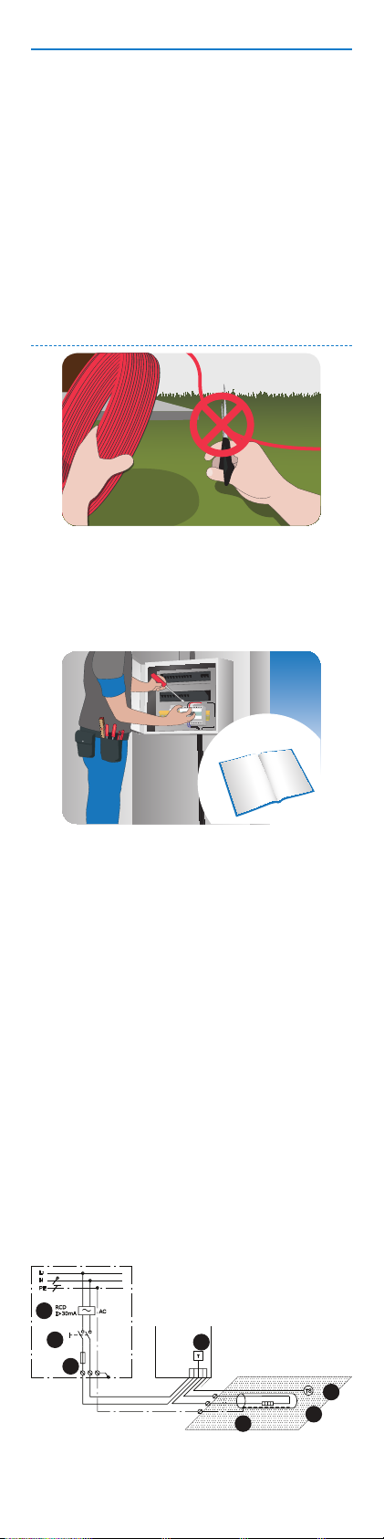
1. Heating cable
2. Thermostat
3. Sensor
4. Screen
5. RCD
6. All-pole switch
7. Fuse
The presence of a heating mat must
• be made evident by axing caution signs or
markings at the power connection ttings and/
or frequently along the circuit line where clearly
visible
• be stated in any electrical documentation
following the installation.
Never exceed the maximum heat density (W/m
or W/m) for the actual application.
Connections
• Phase - Brown
• Neutral - Blue
• Earth - Screen
1.2 Installation guidelines
Prepare the installation site properly by removing
Regularly measure ohmic resistance and insula-
tion resistance before and during installation.
Do not lay heating elements under walls and xed
sharp objects, dirt, etc.
obstacles. Min. 6 cm air is required.
Keep elements clear of insulation material, other
heating sources and expansion joints.
Page 5

Elements may not touch or cross themselves or
other elements and must be evenly distributed
The elements and especially the connection must
be protected from stress and strain.
The element should be temperature controlled
and not operate at ambient temperature higher
than 10°C in outdoor applications.
on areas.
2 Installation step by step
2.1 Calculating C-C distance
The C-C distance is the distance in centimetres from
the centre of one cable to the centre of the next.
C - C [cm] =
or
C - C [cm] =
• Max. C-C distance in ground heating is 20 cm.
• Heating cable bending diameter must be at
least 6 times cable diameter.
• The actual cable length may vary +/- 2 %.
C-C
[cm]
7,5 267 333 400
10 200 250 300
12,5 160 200 240
15 133 167 200
20 100 125 150
25 80 100 120
2.2 Planning the installation
Draw a sketch of the installation showing
• element layout
• cold leads and connections
• junction box/cable well (if applicable)
• sensor
• connection box
• thermostat
W/m² @
20 W/m
5 400 500 -
Area [m]
Cable length [m]
Cable output [W/m]
Heat density [W/m]
230V/400V
W/m² @
25 W/m
x 100 cm
x 100 cm
W/m² @
30 W/m
Page 6

Save the sketch
• Knowing the exact location of these components makes subsequent troubleshooting and
repair of faulty elements easier.
Please the following:
• Observe all guidelines - see section 1.2 .
• Observe correct C-C distance (heating cables
only) - see section 2.1.
• Observe required installation depth and
possible mechanical protection of cold leads
according to local regulations.
• When installing more than one element, never
wire elements in series but route all cold leads
in parallel to the connection box.
• Two or more elements may be installed in
the same room but a single element is not
to be installed across two or more rooms.
• All heating elements in the same room must
have the same heat density (W/m) unless
they are connected to separate oor sensors
and thermostats.
• For single conductor cables, both cold leads
must be connected to the connection box.
2.3 Preparing the installation area
• Remove all traces of old installations, if applicable.
• Ensure that the installation surface is even,
stable, smooth, dry and clean.
• If necessary, ll out gaps around pipes,
drains and walls.
• There must be no sharp edges, dirt or foreign
objects.
3 Installing elements
It is not recommended to install elements at temperatures below -5 °C.
At low temperatures, heating cables can become
rigid. After rolling out the element, briey connect
it to the mains supply to soften the cable before
fastening.
Measuring Resistance
Measure, verify and record element resistance during installation.
• After unpacking
• After fastening the elements
• After the installation in nalized
If ohmic resistance and insulation resistance are not
as labelled, the element must be replaced.
Page 7

• The ohmic resistance must be within -5 to +10
12
≥
1
2
% of the value labelled.
• The insulation resistance should read >20 M
after one minute at min. 500V DC.
3.1 Installing heating elements
Observe all instructions and guidelines in section 1.1
and 1.2.
Heating elements
• Position the heating element so that it is at
least half the C-C distance from obstacles.
• Elements must always be in good contact with
the heat distributor (e.g. concrete).
Heating mats
• Always roll out heating mats with the heating
cables facing up.
• When the heating mat reaches the area boundary, cut the liner/net and turn the mat before
rolling it back.
Extending cold leads
• Avoid extending cold leads if possible. Wire
cold leads to e.g. junction boxes or cable wells.
• Be aware of power loss in the cable according
to local regulations.
3.2 Sensor Installation
• The oor sensor should be mounted in an insulating conduit, sealed at the oor end, for easy
replacement of the sensor if required.
• The oor sensor must be considered a LIVE cable; therefore any extension made to the sensor
wiring should be treated in the same way as
normal mains voltage cabling.
• The sensor can be extended up to a total of 50
m using 1.5 mm installation cable.
• The minimum bending radius for the pipe is 50
mm (1).
• The sensor cable must be placed between two
loops of the heating cable (2).
• Route the conduit to the connection box.
Page 8

4 Applications
1
2
3
4
5
1
2
345
6
7
1
2
3
4
5
6
7
4.1 Snow melting on ground areas
Free constructions, e.g. platforms, steps,
bridges, and terraces
1. Top layer of concrete slab or mastic asphalt.
2. Heating cable.
3. DEVIclip™ fastening accessory or mesh
reinforcement.
4. Underlying free construction.
5. Insulation (optional)
Ground areas, e.g. ramps and car parks
1. Top layer of concrete slab or asphalt concrete.
2. Sand bed or concrete or asphalt concrete.
3. Heating cable.
4. DEVIclip™ fastening accessory or mesh
reinforcement.
5. Supporting layer of crushed stones / concrete / old asphalt.
6. Insulation (optional, ensure supporting layer
is suitable).
7. Soil.
Ground areas, e.g. driveways, walkways and
pavements
Page 9

1. Top layer of pavement blocks or concrete slab
2. Sand bed
3. Heating cable
4. DEVIclip™ fastening accessory or mesh
reinforcement
5. Supporting layer of crushed stones
6. Insulation (optional, ensure supporting layer
is suitable)
7. Soil
Ground thermostat is mandatory
• In sand bed: mat output from 250 W/m and
cable output from 25 W/m.
• In mastic asphalt or concrete bed: cable output
from 30 W/m with a heat density > 500 W/m
(C-C < 6 cm) (DEVIasphalt™ (DTIK)).
Limited power supply
• Reduce the area to be heated, e.g. by heating
tire tracks instead of the whole driveway.
• Divide and prioritise the area into 2 zones by
means of DEVIreg™ 850 .
• Install less W/m² than recommended. Snow
melting performance will be reduced. Do not
install less W/m than recommended in areas of
drainage, e.g. in front of heated steps.
Do not install cables in sand only
• The heating cables must be protected by a hard
top layer.
Embedding in concrete, mortar or screed
• The bedding must not contain sharp stones.
• Must be suciently wet, homogeneous, free of
air voids:
• Pour at a moderate delivery speed to avoid
displacement of the element.
• Avoid excessive use of rakes, shovels, vibrators, and rollers.
• Allow a drying time of approximately 30 days
for concrete and 7 days for moulding compounds.
Embedding in mastic or asphalt concrete (road
asphalt)
• Use DEVIasphalt™ (DTIK) only, fully embedded.
• Use mastic asphalt cooled down to max. 240°C
or 3 cm hand rolled asphalt concrete (max. 8
mm. stone size), cooled down to max. 80°C
before applying a second layer with a max. 500
kg drum size (no vibrator).
• Apply ground sensor dummy Ø100 x H 100
mm, made from heat resistant material, e.g.
cellular glass insulation.
• Apply Sensor conduit 5/8”-3/4” made from heat
resistant material, e.g. metal.
Installation summary
Prepare installation surface with DEVIclip™ fastening accessories and / or mesh reinforcement. Fix
conduit for sensor cable and sensor tube / dummy
for DEVIreg™ 850 sensor, if any.
Page 10

Extend cold leads with connection sets and place
connections in a dry place. Seal all penetrations
through walls or similar structures. Apply caution
tape above cold leads.
After laying blocks or pouring concrete / asphalt,
install external sensor(s), and extend sensor
cable(s) according to sensor manual.
5 Optional settings
If the element is connected to a thermostat such as
a DEVIreg™, congure basic settings according to
the table below and as described in the thermostat
installation manual.
If applicable, adjust the temperature limit in accordance with the manufacturer’s recommendations in
order to prevent damage.
Thermostat Max. load
DEVIreg™ 316 16A -
DEVIreg™ 330 16A On < +3° C
DEVIreg™ 610 10A On < +3° C
DEVIreg™ 850 2 x 15A
Snow and ice melt-
ing on ground areas
Melting < +3° C,
Standby < -3° C
VIJXE102
 Loading...