

Installation guide
2-
2+
1-
1+
Black
Black
120 mm
5 mm
4.7 in
50 mm
134 mm
268 mm
5 mm
11 121314
15 16
Load [A]
DC 24 V 10 A
(Fig.9)
0.2 in 0.2 in
2 in
5.3 in
5.4 in
11 in
120 mm
5 mm
138 mm
125 mm
4.7 in
50 mm
134 mm
268 mm
5 mm
10
60
1
10
20
Buer time
Time [min] Time[h]
0
1234
5678910
11 121314
15 16
Load [A]
2-
2+
1+
2-
2+
1+
Press > 2 sec.
t
max
[min]
24 V 0.2 A
I < I
N
13 23 33
R1 R214 24 34
Stick
UPS
Stick
UPS
DC 24 V 10 A
OFF
ON
InputOutput
2
6
7
5
1
3
(Fig.9)
0.2 in 0.2 in
2 in
4.9 in
5.3 in
5.4 in
11 in
Custom
(Default 0.5)
ICAD-UPS for
ICM motor operated valves
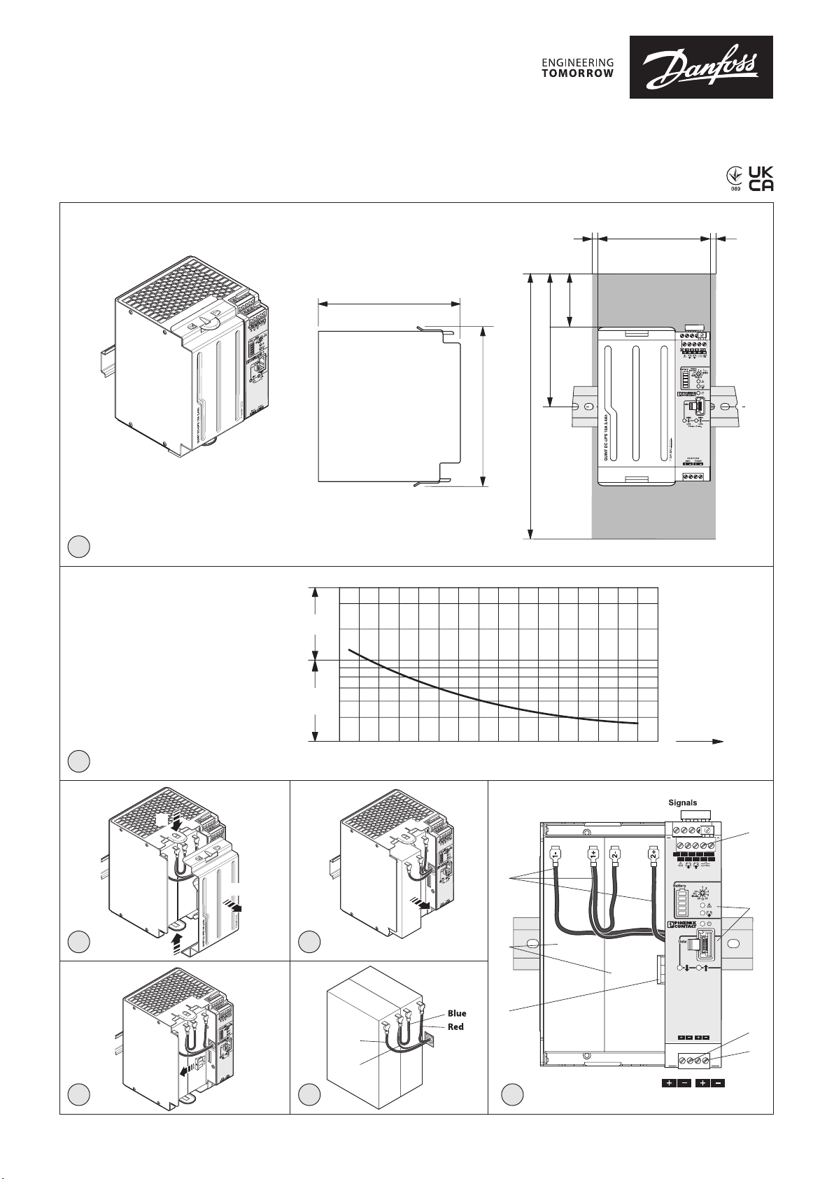
ICAD-UPS dimensions/space requirements
027R9982
Danfoss code no.: 027H0388
1
Current output at power failure
5 mm
0.2 in 0.2 in
120 mm
4.7 in
5 mm
027R9982
125 mm
4.9 in
2+
2-
1+
5.4 in
138 mm
268 mm
20
10
1
60
Buer time
Buer time
11 in
134 mm
5.3 in
50 mm
2 in
2
A
3
2+
2-
1+
2+
2-
B
A
1+
4
Імпортер:ТОВ з іі “Данфосс ТОВ” 04080, Київ 80, п/с 168, Україна
© Danfoss | Climate solutions | 2022.04
Time [min] Time[h]
10
0
1234
5678910
2+
1+
1-
11 121314
15 16
Load [A]
1
I < IN13 23 33
24 V 0.2 A
R1 R214 24 34
OFF
ON
7
(Default 0.5)
Custom
t
max
[min]
2
5
Black
Black
6
2+
2-
1+
1-
6
Stick
Stick
UPS
UPS
Press > 2 sec.
5
DC 24 V 10 A
InputOutput
3
4
Input
Output
7
Info for UK customers only:Danfoss Ltd., 22 Wycombe End, HP9 1NB, GB
AN394639594861en-000201 | 1
AWG
14-12
L
7
[Nm] [lb in]
0,5-0,6
5-7
Input DC
14-12
24-12
7
7
0,5-0,6
0,5-0,6
5-7
5-7
Output DC
Signals
[mm²]
0,2-2,5
[mm²]
0,2-2,5
0,2-2,5
0,2-2,5
0,2-2,5
0,2-2,5
13
23
33
14
24
34
R1
R2
Alarm
Bat.Mode
Bat.Charge
Remote
Confirm
Data-Port
Input
DC 24 V
Output
DC 24 V
24 V 0,2 A
I < I
N
t [min]
max
Battery
DC 24 V
0.3
[mm]
[in]
0.3
0.3
13
23
33
14
24
34
R1
R2
24 V 0,2 A
I < I
N
AWG
14-12
L
7
[Nm] [lb in]
0,5-0,6
5-7
Input DC
14-12
24-12
7
7
0,5-0,6
0,5-0,6
5-7
5-7
Output DC
Signals
[mm²]
0,2-2,5
[mm²]
0,2-2,5
0,2-2,5
0,2-2,5
0,2-2,5
0,2-2,5
13
23
33
14
24
34
R1
R2
Alarm
Bat.-
Mode
Bat.-
Charge
Remote
Confirm
Data-Port
Input
DC 24 V
Output
DC 24 V
24 V 0,2 A
I < I
N
t [min]
max
Battery
DC 24 V
0.3
[mm]
[in]
0.3
0.3
13
23
33
14
24
34
R1
R2
24 V 0,2 A
I < I
N
-
AWG
14-12
L
7
[Nm] [lb in]
0,5-0,6
5-7
Input DC
14-12
24-12
7
7
0,5-0,6
0,5-0,6
5-7
5-7
Output DC
Signals
[mm²]
0,2-2,5
[mm²]
0,2-2,5
0,2-2,5
0,2-2,5
0,2-2,5
0,2-2,5
13
23
33
14
24
34
R1
R2
Alarm
Bat.-
Mode
Bat.-
Charge
Remote
Confirm
Data-Port
Input
DC 24 V
Output
DC 24 V
24 V 0,2 A
I < I
N
t [min]
max
Battery
DC 24 V
0.3
[mm]
[in]
0.3
0.3
13
23
33
14
24
34
R1
R2
24 V 0,2 A
I < I
N
+
-
+
-
CAD-U
S
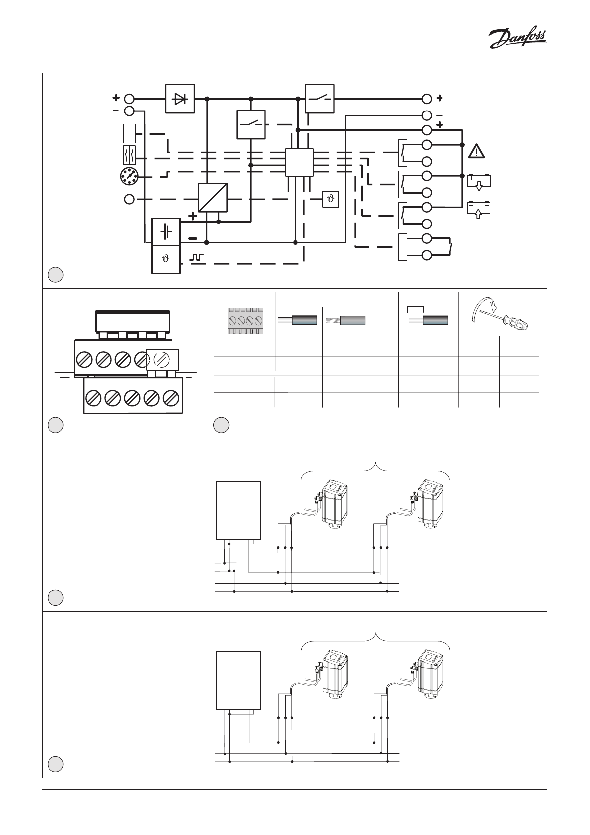
maximum 8 pcs. of ICAD 600 or maximum 3 pcs. of ICAD 1200
Input Output
Black
White
Brown
Black
White
Brown
+
-
+
-
DC 24 V
DC 24 V
-
ICAD-UPS
AWG
14-12
L
7
[Nm] [lb in]
0,5-0,6
5-7
Input DC
14-12
24-12
7
7
0,5-0,6
0,5-0,6
5-7
5-7
Output DC
Signals
[mm²]
0,2-2,5
[mm²]
0,2-2,5
0,2-2,5
0,2-2,5
0,2-2,5
0,2-2,5
13
23
33
14
24
34
R1
R2
Alarm
Bat.-
Mode
Bat.-
Charge
Remote
Confirm
Data-Port
Input
DC 24 V
Output
DC 24 V
24 V 0,2 A
I < I
N
t [min]
max
Battery
DC 24 V
0.3
[mm]
[in]
0.3
0.3
8
N
14
13
24
23
33
34
24 V 0,2 A
R2
R1
DC 24 V
DC 24 V
Signal terminals
I < I
9 10
Seperate 24 V DC Transformer for the
ICAD-UPS and ICAD 600/1200
11
Shared 24 V DC Transformer for the
ICAD-UPS and ICAD 600/1200
Input Output
+
+
-
+
Input Output
+
CAD-U
ICAD-UPS
-
CAD-U S
ICAD-UPS
-
S
+
-
+
-
Black
White
Brown
maximum 8 pcs. of ICAD 600 or maximum 3 pcs. of ICAD 1200
maximum 8 pcs. of ICAD 600 or maximum 3 pcs. of ICAD 1200
Black
White
Brown
12
© Danfoss | Climate solutions | 2022.04
DC 24 V
Black
White
Black
White
+
Brown
Brown
AN394639594861en-000201 | 2

Technical Data
Input data Battery charge
Nominal input voltage 24 V DC Status display Red/Green LED Bargraph
Input voltage range 18 V DC – 30 V DC
Current consumption 14 A
Output data (mains operation) Signal supply
Nominal output voltage 24 V DC Switching voltage Buered ≤ 24 V DC 200 mA
Output voltage range (depending on the
input voltage)
Output current with convection cooling Remote control
Nominal output current Permanent
Power Boost
SFB technology 12 ms
Output data (battery operation)
Nominal output voltage 24 V DC
Output voltage range (depending on the
batter y voltage)
Output current with convection cooling Battery type Panasonic UP-VW1220P1
Output current with convection cooling
Nominal output current Permanent
Power Boost
SFB technology 15 ms
Buer time (IOUT = ) 180 min. (1 A) / 10 min. (10 A)
Connection types
Connection in parallel Yes 2
Connection in series No
Signaling
Power In OK
Status display Green LED
Alarm
Status display Red
Switching output Relay
(Preset: switching output - active low)
Battery mode
Status display Yellow
Switching output Relay
(Preset: switching output - active high)
I
N
I
N
I
N
18 V DC – 30 V DC Switching current Short-circuit-proof
10 A
15 A
60 A
19,2 V DC – 27,6 V DC
(UOUT = UBAT - 0,5 V DC)
10 A
15 A
65 A
LED
30 V AC/DC , ≤ 100 mA
LED
30 V AC/DC , ≤ 100 mA
Switching output Relay
(Preset: switching output - active high)
Version 1
Output R1 to input R2 Plug-in-bridge
Version 2
Input R2
Input current R2
Energy storage
Memory medium Lead rechargeable
battery module, 3.4 Ah
Nominal voltage 24 V DC
End-of-charge voltage (temperature
compensated)
Capacitance 3,4 Ah
Charging current ICHARGE 2,88 A
Battery service life 6 – 9 (20 °C)
Latest startup
General data
Degree of protection / Protection class IP20 / III
Degree of pollution 2
Ambient temperature (operation) 0 °C – 40 °C
Ambient temperature (storage/transport) -15 °C – 40 °C
Humidity at 25 °C, non-condensing ≤ 95 %
Dimensions (W/H/D) 120 x 169 x 125 mm
Weight 3,8 kg
U
N
Months 6 (0 °C – 20 °C)
Months 6 – 3 (20 °C – 30 °C)
Months 3 – 1 (30 °C – 40 °C)
30 V AC/DC , ≤ 100 mA
24 V DC
200 mA
24 V DC – 29 V DC
© Danfoss | Climate solutions | 2022.04
AN394639594861en-000201 | 3

ENGLISH
Uninterruptible power supply with integrated battery
ICAD-UPS is dedicated for use along with ICM sizes 20-150 installed
with ICAD 600A and ICAD 1200A actuators.
In the event of power failure, there is a need to make sure that the
ICM goes to a safe position.
Danfoss ICAD-UPS can be connected to the ICAD 600A / 1200A.
The solution ICM with ICAD connected to ICAD-UPS with default
speed and boost value (i30 and i31) will give one of the following
possibilities in the event of power failure:
– close ICM
– open ICM
– stay
– go to a specic ICM Opening Degree
When power supply has been re-established the system will
automatically return to normal operation.
The uninterruptible power supply (UPS) is equipped with an
integrated energy storage system. The internal energy storage
system is monitored continuously by the battery management
system.
Features
• UPS with integrated energy storage
• Integrated temperature sensor for optimized battery charging
• Energy storage system
Safety and warning instructions
Only professionals may install and start up the device. Regulations
specic to the country must be observed.
• Never carry out work on live parts
• Establish connection correctly and ensure protection against
electric shock
• Use a current-limited source or a suitable fuse (≤15 A)
• When connecting the individual battery blocks, ensure the
correct polarity and avoid short circuits on the pole terminals
• Following installation, cover the terminal area to prevent
accidental contact with live parts (e.g., installation in a control
cabinet)
• Observe mechanical and thermal limits
• The location must allow for sucient ventilation
• Keep ames, embers or sparks away from the module
• When changing the battery, use only battery blocks of the same
type with the same batch number
• The battery blocks are maintenance-free and may not be
opened
• When storing the UPS, pay attention to the latest startup date
of the battery set, and recharge the battery set if necessary
• Prior to transporting the UPS, remove the DC fuse in the battery
compartment
• Do not disconnect the DC fuse and/or the battery wiring under
Hazloc conditions
Initial charging of the battery
Prior to starting the UPS up in your application, connect the
UPS to a voltage source and charge the battery set for
24 hours.
1. Designation of the elements (g. 7)
1. Connection terminal blocks for signals
2. Status indicators/IFS interface/Selector switch
(Activation threshold)
3. Connection terminal blocks for DC input
4. Connection terminal blocks for DC outputs
5. Internal DC fuse (batteries)
6. Battery set (2 battery blocks)
7. Battery connecting cables (polarity- and color-coded)
1.1 LED status indicators/LED bar graph
The UPS status is displayed via LEDs in dierent colors and ash
sequences.
The oating switching outputs switch depending on the current
device status.
2. Opening/closing the battery compartment (g. 3)
• Press the locking buttons on the battery compartment
• Carefully remove the battery compartment cover
• You can now carry out the work to be done
• Then press the battery compartment cover onto the locking
latches
3. DCC fuse (g. 4)
The UPS is equipped with an internal pluggable DC fuse as
protection during transport and for protecting the cabling.
Always remove the DC fuse prior to transporting to the UPS.
To start up the UPS, plug the DC fuse back into the fuse
holder.
A faulty/blown DC fuse must be replaced by a fuse of the
same type.
4. Battery connecting cables (g. 6)
Check the battery wiring for the individual battery blocks
for the correct polarity and color coding.
508:
Use copper cables for operating temperatures of
> 75 °C (ambient temperature < 55 °C)
> 90 °C (ambient temperature < 75 °C)
60950:
Use ferrules for exible cables
Tighten screws on all unused terminals
A. Suitable for a max. altitude of 2000 m
B. Suitable for indoor use only
C. Clean only with water
D. Power source shall be double isolated from hazardous voltages
E. Protection may be impaired if the equipment is used in a manner
not specied by the manufacturer
F. This equipment is suitable for use in class I, Division 2, Groups A,
B, C and D or non-hazardous locations only
G. For all models the following end-product enclosures are
required: Mechanical, Fire, Electrical
H. Warning - Explosion hazard - Do not disconnect equipment
unless power has been removed or the area is known to be free
of ignitable concentrations
I. Note - Explosion hazard - Substitution of components may
impair suitability for use in potentially explosive areas
(CLASS 1; DIVISION 2)
J. Warning - Explosion hazard: Do not replace fuse unless power
has been switched o or the area is known to be
non-hazardous
K. Warning - Explosion hazard: Do not remove or replace battery
while the circuit is live or unless the area is known to be free of
ignitable concentrations
Notes on disposal
Do not dispose of used batteries in the household waste!
Dispose of these according to the currently valid national
regulations.
© Danfoss | Climate solutions | 2022.04
AN394639594861en-000201 | 4
 Loading...