

Page 1
Installation guide
Actuator
Type ICAD 600A / ICAD 600A-TS / ICAD 1200A
ICAD 600A
ICAD 600A-TS
027R9966
ICAD 600A /
ICAD 600A-TS
ICAD 1200A
1 2
Before installing ICAD on ICM please read
the separate installation guide
“Mechanical intallation of ICAD on ICM”
(document nu mber AN2852526 68332).
Vor Montage des ICAD auf das ICM bitte
die separate Montageanleitung
„Mechanische Montage des ICAD
auf das ICM” (Dokument Nummer
AN2852526 68332) lesen.
Avant d’installer ICAD sur l’ICM, veuillez
lire le guide d’installation séparé
« Installation mécanique d’ICAD sur l’ICM »
(document nu méro AN2852526 68332).
Antes de instalar el ICAD en el ICM, lea la
guía de instalación por separado
«Instalación mecánica del ICAD en el ICM»
(número de documento AN285252668332).
ICAD 1200A
027R9966
2.5 mm
Nm LB-feet
3 2.5
3 4
mm in.
H 45 1.77
5a
ICM + ICAD 600A/ICAD 600A-TS
© Danfoss | Climate solutions | 2021.11
L
3
25 1
5b
ICM + ICAD 1200A
Info for UK customers only:Danfoss Ltd. Oxford Road, UB9 4LH Denham, UK
AN19798642980802-000802 | 1
Page 2

ICAD 600A / ICAD 600ATS / ICA D 1200A
III
I
II
C
D
E
B
A
G
F
External
voltage
24 V DC
(+)
(–)
K
1
K
2
K1K
2
II III
Supply
D F G E
DI1
DI2
Control
ICAD
Danfoss
M27H0163_1
7
C 315A
A (Black)
B (Brown)
C (Red)
D (Orange)
E (Yellow)
F (Green)
G (Blue)
DC
Reference
Bezeichnung
Référence
Referencia
A Black / Schwarz / noir / Negro –
B Brown / Braun / Marron / Marrón –
C Red / Rot / rouge / Rojo –
4 pin male connector
4-Pin-Stecker
connecteur mâle
à 4 broches
Conector macho
de 4 terminales
8 pin male connector
8-Pin-Stecker
connecteur mâle
à 8 broches
Conector macho
de 8 terminales
6
ICAD 600A/1200A - Analog I/O for modulating control/Analoger E/A für die modulierende Regelung/E/S analogique pour régulation modulante/E/S analógica para control modulante
D Orange / Orange / orange / Naranja – GND ground/Masse/Masse GND/GND
E Yellow / Gelb / Jaune / Amarillo + 0/4 – 20 mA Input/Eingang/Entrée/Entrada
F Green / Grün / Vert / Verde + 0/2 – 10 V Input/Eingang/Entrée/Entrada
G Blue / Blau / Bleu / Azul + 0/4 – 20 mA Output/Ausgang/Sortie/Salida
I Black / Schwarz / noir / Negro +
II White / Weiß / Blanc / Blanco + Supply voltage 24 V DC/Versorgungsspannung 24 V DC
III Brown / Braun / Marron / Marrón –
*Uninterruptible Power Supply / Unterbrechungsfreie Stromversorgung /
Alimentation sans interruption / Fuente de alimentación ininterrumpida
Color
Farbe
Couleur
Color
Description
Beschreibung
du marché
Descripción
Common Alarm/Sammelalarm /
Alarme commune/Alarma común
Valve fully open/Ventil voll geöffnet/Vanne totalement
ouverte/Válvula completamente abierta
Valve fully closed/Ventil voll geschlossen/Vanne
totalement fermée/Válvula completamente cerrada
Fail safe supply - Battery/UPS* 19 V DC /
Eigensichere Stromversorgung – Batterie/USV* 19 V DC
Alimentation de sécurité - Batterie/onduleur* 19 V CC
Alimentación de seguridad (batería/SAI*, 19 V CC)
Tension d’alimentation 24 V CC
Tensión de alimentación, 24 V CC
Digital output
Digitaler Ausgang
Sortie numérique
Salida digital
}
Analog in/output
Analoger Ein-/Ausgang
Entrée/sortie analogique
}
Entrada/salida analógica
Terminal box
Klemmkasten
Boîtier
Caja terminal
Control cable / Regelkabel /
Câble de commande /
Cable de control
Supply cable / Versorgungskabel /
Câble d’alimentation / Cable de
alimentación
A (Black)
B (Brown)
C (Red)
D (Orange)
E (Yellow)
F (Green)
G (Blue)
(Black)
(White)
(Brown)
Only possible with EKC 347
Nur mit EKE 347 möglich.
Possible uniquement avec l’EKE 347
Sólo posible con EKE 347
EKC 347
EK
EKC 361
Terminal box
Klemmkasten
Boîtier
Caja terminal
Control cable / Regelkabel /
Câble de commande /
Cable de control
Supply cable / Versorgungskabel /
Câble d’alimentation / Cable de
alimentación
A (Black)
B (Brown)
C (Red)
D (Orange)
E (Yellow)
F (Green)
G (Blue)
(Black)
(White)
(Brown)
Only possible with EKE 347
Nur mit EKE 347 möglich.
Possible uniquement avec l’EKE 347
Sólo posible con EKE 347
Only possible with EKE 347
Nur mit EKE 347 möglich.
Possible uniquement avec l’EKE 347
Sólo posible con EKE 347
EKE 34
7
ICAD 600A/600A-TS/1200A - Digital I/O for ON/OFF valve operation / Digitaler E/A für EIN/AUS-Ventilbetrieb /E/S numérique pour marche/arrêt de la vanne /E/S digital para control de válvula ON/OFF
Terminal box
Klemmkasten
Boîtier
Caja terminal
Auxiliary relays/Hilfsrelais/
Relais auxiliaires/Relés auxiliares
Control cable / Regelkabel /
Câble de commande /
Cable de control
Supply cable / Versorgungskabel /
8
Neutral zone/3 points control/Neutralzone/3-Punkt-Regelung/Zone neutre/régulation 3 points/Zona neutra/control de 3 puntos
9
2 | AN19798642980802-000802
Câble d’alimentation / Cable de
alimentación
© Danfoss | Climate solutions | 2021.11
Page 3
ENGLISH
Installation
Do not install ICAD before welding. This apply
for electrical as well as for mechanical installation. Please observe that ICAD when connected
to 24 V DC, will send out acoustic noise at stand
still. This has no influence on the function/
operation of the ICAD.
NOTE!
If media temperature is lower than
-30 °C (-22 °F) it is mandatory to set
parameter ¡30 and ¡31.
See separate document attached in ICAD
box: document number AN285243155312
Use
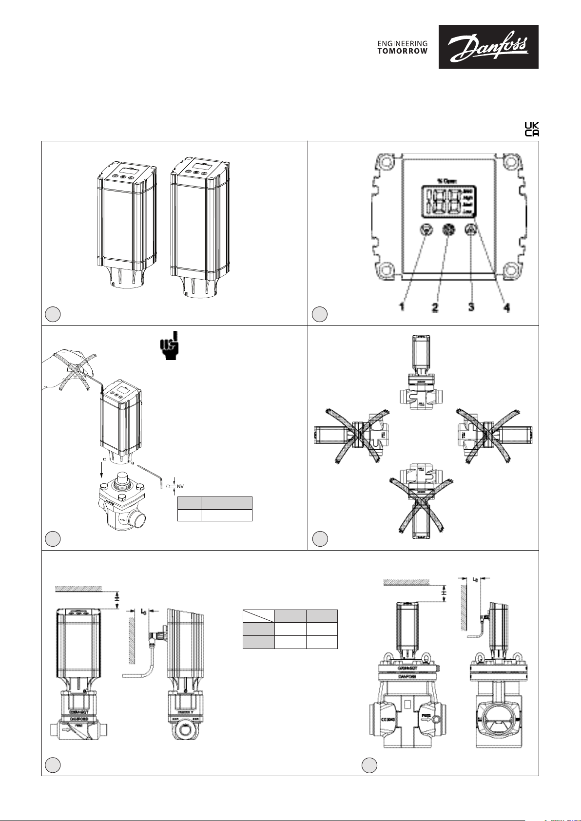
ICAD 600A, ICAD 600A-TS and ICAD 1200A can
be used together with the following Danfoss
valves (fig. 1, 5a and 5b).
ICAD 600A ICAD 600A-TS ICAD 1200A
ICM 20 ICMTS 20 ICM 40
ICM 25 ICM 50
ICM 32 ICM 65
ICM 100
ICM 125
ICM 150
CVE pilot valve
Electrical data
Supply voltage is galvanically isolated from in-/
output.
Supply voltage
24 V DC (Tolerances; see below table)
Load ICAD 600A, ICAD 600A-TS: 1.2 A
ICAD 1200A: 2.0 A
24 Volt DC ONLY
Please observe cable voltage drop.
Distance between the applied DC
transformer and the ICAD terminal
box may cause a voltage drop. Cross
section of cables and size of DC
transformer must be calculated so that
the voltage at all time at the ICAD terminal
box*, both during standstill and during
operation of ICAD, is within this range:
Prefabricated
ICAD cable length
Code number
Voltage ICAD terminal
(600A/1200A) [V DC]
* Do not meas ure inside the ICAD i tself.
Fail safe supply
24 V DC (Tolerances; see table above)
Load ICAD 600A, ICAD 600A-TS: 1.2 A
ICAD 1200A: 2.0 A
Anolog Input - Current or Voltage
Current
0/4 – 20 mA
Load: 200 W
Voltage
0/2 – 10 V DC
Load: 10 kW
Analog Output
0/4 – 20 mA
Load: ≤ 250 W
Digital Input - Digital ON/OFF input by means of
voltfree contact (Signal/Telecom relays with goldplated contacts recommended) – Voltage input used
ON: Contact impedance < 50 W)
OFF: Contact impedance > 100 kW
Digital Output - 3 pcs. NPN transistor output
External supply: 5 – 24 V DC (same supply as
Output load: 50 W
Load: Max. 50 mA
1.5 m
3 m
027H0426
Min. 21 22 23 24
Max. 26.4
027H0438
10 m
027H0427
027H0435
for ICAD can be used, but
please note that the
galvanically isolated system
will then be spoiled).
15 m
Temperature range (ambient)
-30 °C/+50 °C (-22 °F/122 °F)
Enclosure
IP67 (~NEMA 6)
Electrical connection
Connection to ICAD is done via M12 connectors.
ICAD has two M12 male connectors build-in:
Power supply: 4 poled M12 male connector
Control signals: 8 poled M12 male connector
If ICAD is delivered with cables (1.5 m. (60 in.))
M12 female connectors: (Cable set with M12
female connectors in other lengths are available)
Power Supply cable with 4 poled M12
female connector
3 x 0.34 mm2 (3 x ~22 AWG) (fig. 6)
I: Black (+) 19 – 24 V DC fail safe
supply (optional).
II: White (+) 24 V DC
III: Brown (–) 24 V DC
Control cable with 8 poled M12
female connector
7 x 0.25 mm2 (7 x ~24 AWG) (fig. 7)
A: Black (–) Digital output.
Common Alarm.
B: Brown (–) Digital output.
ICM fully open.
C: Red (–) Digital output.
ICM fully closed.
D: Orange (–) GND - Ground.
E: Yellow (+) Analog input
0/4 – 20 mA. *)
F: Green (+) Analog input 0/2 – 10 V /
DI1 - Digital ON/OFF
input.
G: Blue (+) Analog output
0/4 – 20 mA. *)
*) If Neutral zone / 3 point control is
selected (parameter i02 = 3) then
E and G is used as DI2 - Digital
ON/OFF input. Se fig. 9.
Electrical installation
General procedure for ICAD 600A/ICAD
600A-TS/1200A installed on all ICM, ICMTS & CVE
valves.
All necessary electrical connections to be made.
ICM valve: Analog or digital operation
CVE/ICMTS valve: Analog only
Fig. 6
Analog operation - 7 wired cable (A-G)
Modulation control. Valve to be controlled
from Danfoss electronics, type EKC/EKE (fig.
7), or third party electronics
(like e.g. PLC).
Connect analog input signals. Currrent
(mA) or Voltage (V). See Parameter list for
configuration of analog input signals.
Yellow (+) and Orange (GND) are used for
current (mA) input.
or
Green (+) and Orange (GND) are used for
Voltage (V) input.
Blue (+) and Orange (GND) are used
for current (mA) output (optional, not
mandatory).
Fig. 6
Digital operation - 7 wired cable (A-G)
ON/OFF ICM solenoid valve operation. ICM
valve to be controlled by means of a digital
voltfree contact.
Connect digital input signals (fig. 8). See
Parameter list for configuration of digital
input signals.
Green (+) and Orange (GND) are connected
to a voltfree contact.
Digital output signals are optional, not
mandatory.
Black (–) and Orange (GND) are connected
to auxiliary relay for Common Alarm.
Brown (–) and Orange (GND) are connected
to an auxiliary relay indicating ICM fully
open.
Red (–) and Orange (GND) are connected
to an auxiliary relay indicating ICM fully
closed.
Supply voltage - 3 wired cable (I, II, III)
ICAD must be connected to a normal
24 V DC supply. As an option, a fail safe
supply is possible by means of a battery or
UPS (Uninterruptible Power Supply). When
voltage is applied as described below, ICAD is
ready to be configurated. See Parameter list.
ICAD configuration can be done
independently whether the ICAD is installed
on the valve or not.
See Mechanical installation.
Connect the White (+) and Brown (–) to a
24 V DC supply voltage (fig. 6).
Fail safe supply as an option (not mandatory).
Connect the Black (+) and Brown (–) to a fail
safe supply.
Mechanical installation
General procedure for ICAD 600A/ICAD
600A-TS/1200A installed on all valves (fig. 3).
Check that the three socket set screws are
fully unscrewed counter clockwise with a
2.5 mm Hexagon key.
Mount ICAD by slowly lowering it on top of
the valve.
The magnet coupling will drag the valve and
ICAD together and in position.
Push ICAD in place.
Fasten valve and ICAD with the three socket
set screws using a 2.5 mm Hexagon key.
Special moisture seal is damaged if
screws are removed (fig. 3, pos. A)
Neutral zone / 3 point control (fig. 9 - ICM only)
¡02 = 3
When ¡02 = 3 the factory setting of ¡04
(opening) and ¡14 (closing) are both set to 10.
When ¡02 = 3 the speed given by ¡04 (opening)
and ¡14 (closing) are active
¡13 (Inverse operation) is active
¡16 = 1 (Encoder operation enable) is active.
¡13 = 0 (Direct operation)
DI1 = DI2 = OFF
ICAD/ICM maintain current position
DI1 = DI2 = ON
ICAD/ICM maintain current position
DI1 = ON, DI2 = OFF
ICAD increase opening degree
DI1 = OFF, DI2 = ON
ICAD decrease opening degree
¡13 = 1 (Inverse operation)
DI1 = DI2 = OFF
ICAD maintain current position
DI1 = DI2=ON
ICAD maintain current position
DI1 = ON, DI2 = OFF
ICAD decrease opening degree
DI1 = OFF, DI2 = ON
ICAD increase opening degree
© Danfoss | Climate solutions | 2021.11
AN19798642980802-000802 | 3
Page 4

ENGLISH
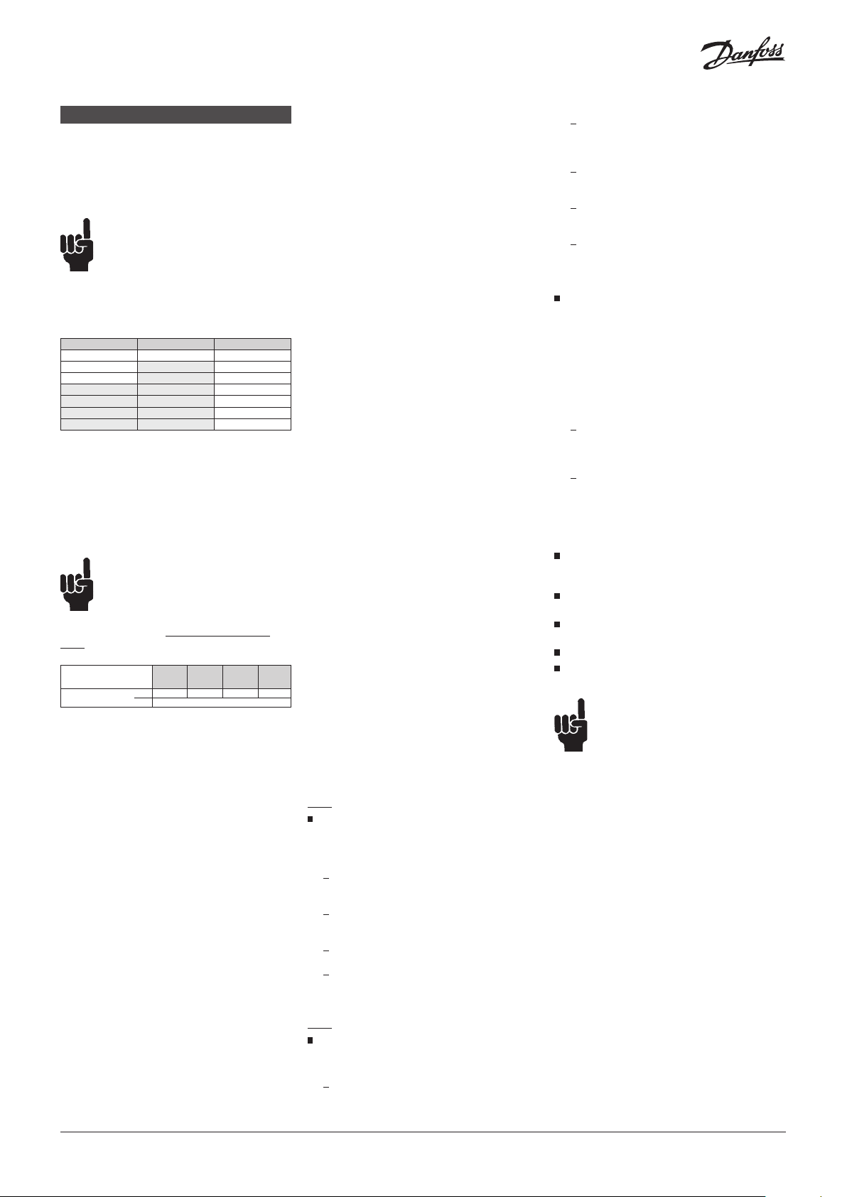
Startup
When voltage is applied for the first time
the display on the ICAD (fig. 2) will alternate
between showing: Actual opening degree and
A1.
A1 indicates an alarm which corresponds
to: No valve selected. See Alarms for further
information.
Please observe that when the correct valve is
entered in parameter ¡26 (see Parameter list)
an automatic calibration is carried out. I.e it is
not necessary to carry out another calibration in
parameter ¡05.
During calibration “CA” will be flashing in the
display.
The ICAD will briefly display “CS” every time the
valve is going to close and reach 0%.
General Operation
ICAD is equipped with an MMI (Man Machine
Interface) from which it is possible to see and
change different parameters to adapt the ICAD
and the corresponding valve to the actual
refrigeration application. The operation of
parameters is done by means of the integrated
ICAD MMI (fig. 2) and consists of:
Gives access to change a value once the
Parameter list has been accessed.
Acknowledge and save change of value of
a parameter.
To exit from the Parameter list and return
to the display of Opening Degree (OD) keep
the push button activated for 2 seconds.
Up arrow push button (fig. 2, pos. 3)
Increases parameter number by 1 for each
activation
Display (fig. 2, pos. 4)
Normally the Opening Degree (OD)
0 - 100 % of the valve is displayed. No
activation of push buttons for 20 seconds
means that the display will always show
OD. Like below:
Displays the parameter
Displays the actual value of a parameter.
Displays the status by means of text
(fig. 2, pos. 4).
Mod represents that ICAD is positioning the
ICM, ICMTS or CVE valve according to an
analog input signal (Current or Voltage).
Low represents that ICAD is operating the
ICM valve like an ON/OFF solenoid valve
with low speed according to a digital input
signal.
Med represents that ICAD is operating the
ICM valve like an ON/OFF solenoid valve
with medium speed according to a digital
input signal.
High represents that ICAD is operating the
ICM valve like an ON/OFF solenoid valve
with high speed according to a digital input
signal. Like below:
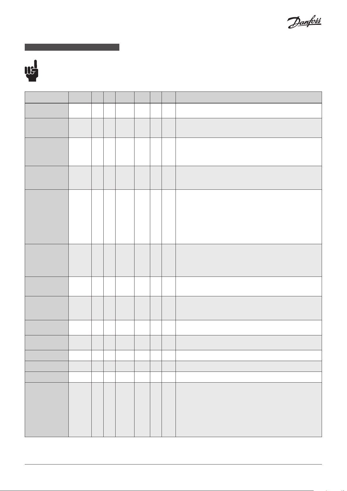
Alarms
ICAD can handle and display different alarms.
If an alarm has been detected the display at
ICAD (fig. 2) will alternate between showing
actual alarm and present Opening Degree.
If more than one alarm is active at the same
time only the alarm with the highest priority
will appear. A1 has the highest priority, A9 the
lowest.
Any active alarm will activate the Common
Digital Alarm output (Normally Open).
All alarms will automatically reset them-selves
when they physically disappear.
Old alarms (alarms that have been active, but
have physically disappeared again) can be found
in parameter ¡11.
Disposal Note
The Product contains
electrical components
And may not be
disposed together
with domestic waste.
Equipment must be separate collected with
Electrical and Electronic waste. According to
Local and currently valid legislation.
1 2 3
Down arrow push button
(fig. 2, pos. 1)
decreases parameter number by 1 for each
activation
Enter push button (fig. 2, pos. 2)
Gives access to the Parameter list by
keeping the push button activated for 2
seconds. A Parameter list is shown below
(parameter ¡08):
Description
No Valve type selected A1 Alarm ON
Controller fault A2 Alarm ON
AI input error A3 Alarm ON
Low voltage of fail safe
Supply
Check supply to ICAD A5 Alarm ON If supply voltage < 18 V
Calibration extended
failed
Internal temperature
alarm
POM mode
(Preventive Operational
Mode)
ICAD alarm
text
Definition of
event
A4 Alarm ON
A6 Alarm ON
A7 Alarm ON
A8 Alarm ON
See
A9
¡18
and
¡21
Comments
At start-up A1 will be displayed
Internal fault inside electronics.
Carry out:
1) Power OFF and Power ON
If A2 still active.
2) Make a Reset to factory setting
If A2 still active. Return ICAD to Danfoss
Not active if ¡01 = 2, or ¡02 = 2
When ¡03 = 1 and AI A > 22 mA
When ¡03 = 2 and AI A > 22 mA
or AI A < 2 mA
When ¡03 = 3 and AI A > 12 V
When ¡03 = 4 and AI A > 12 V
or AI A < 1 V
If 5 V < fail safe supply
<18 V. Enabled by
Check valve type selected.
Check presence of foreign body internally in valve
Temperature for stepper motor component too high.
Ventilate/lower ambient ICAD temperature
Temperature for stepper motor component too high.
Ventilate/lower ambient ICAD temperature.
Only active if
If ICAD meets too high torque from ICM valve
(increased friction/sticking surfaces) ICAD automatic
goes into POM mode to overcome lost step.
(See ¡18 and ¡21)
¡16
¡08
= 1
4 | AN19798642980802-000802
© Danfoss | Climate solutions | 2021.11
Page 5
ENGLISH
Parameter list - Valid from: (¡58:14, ¡59:45) and onwards
The first parameter to be entered shall be: ¡26
Description
OD (Opening degree) - 0 100 % -
Main Switch ¡01 1 2 1
Mode ¡02 1 2 1
AI signal ¡03 1 4 2
Speed
In Modulating Mode
Opening/closing
speed
In ON/OFF Mode
Opening speed
In Neutralzone/
3 point control
Opening speed = 10
Automatic calibration ¡05 0 2 0 - No
AO signal ¡06 0 2 2
Failsafe ¡07 1 4 1
Fail safe supply ¡08 0 1 0
DI function ¡09 1 2 1
Password ¡10 0 199 0 - -
Old Alarms ¡11 A1 A99 - - No
OD at power cut. ¡12 0 100 50
Inverse operation ¡13 0 1 0
ICAD
parameter
Min Max
¡04 1 100 50/ 100
Factory
Setting
Stored Unit
Pass
word
- No
- No
- No
- No
- No
- No
Yes
No
No
No
Comments
ICM/ICMTS valve Opening Degree (CVE pressure setting) is displayed during normal
operation.
Running display value (see ¡01, ¡05).
Internal main switch
1: Normal operation
2: Manual operation. Valve Opening Degree will be flashing. With the down
arrow and the up arrow push buttons the OD can be entered manually.
Operation mode
1: Modulating – ICM, ICMTS & CVE positioning according to Analog Input (see ¡03)
2: ON/OFF - ICM only. Operating the ICM valve like an ON/OFF solenoid valve
controlled via Digital Input. See also ¡09.
3: Neutralzone / 3 point control - ICM only. Increase/Decrease Opening Degree by
Digital Input. See fig. 9
Type of AI signal from external controller
1: 0 – 20 mA
2: 4 – 20 mA
3: 0 – 10 V
4: 2 – 10 V
Speed can be decreased. Max. speed is 100 % - Not active in manual operation (¡01 = 2)
For CVE the speed should not exceed 50 (factory setting)
If ¡26= 1 - 3 then factory setting =100
If ¡26= 4 - 10 then factory setting =50
If the valve is opening and (¡04 < = 33) or the valve is closing and (¡14 < = 33)
=> Low is displayed.
If the valve is opening and (33 < If ¡04 < = 66) or the valve is closing and (33 < If ¡14 < = 66)
=> Med is displayed.
If the valve is opening and (¡04 > = 67) or the valve is closing and (¡14 > = 67)
=> High is displayed"
Not active before ¡26 has been operated.
Always auto reset to 0.
CA will flash in the display during calibration,
if Enter push button has been activated for two seconds
0: No Calibration
1: Normal forced calibration - CA flashing slowly
2: Extended calibration – CA flashing rapidly"
Type of A0 signal for ICM valve position
0: No signal
1: 0 – 20 mA
2: 4 – 20 mA
Define condition at power cut and fail safe supply is installed.
1: Close valve
2: Open Valve
3: Maintain valve position
4: Go to OD given by ¡12"
Fail safe supply connected and enable of A4 alarm:
0: No
1: Yes
Define function when DI is ON (short circuited DI terminals) when ¡02 = 2
1: Open ICM valve (DI = OFF = > Close ICM valve)
2: Close ICM valve (DI = OFF = > Open ICM valve)
Enter number to access password protected parameters: ¡26
Password = 11
Old alarms will be listed with the latest shown first. Alarm list can be reset by means
of activating down arrow and up arrow at the same time for 2 seconds.
Only active if ¡07 = 4
If fail safe supply is connected and power cut occurs, the valve will go to the specified OD.
When ¡02 = 1
0: Increasing Analog Input signal => Increasing ICM Opening Degree
1: Increasing Analog Input signal => Decreasing ICM Opening Degree
When ¡02 = 3
0: DI1 = ON, DI2 = OFF => Increasing valve Opening Degree.
DI1 = OFF, DI2 = ON => Decreasing valve Opening Degree
DI1 = DI2 = OFF => ICAD/ICM maintain current position
DI1 = DI2 = ON => ICAD/ICM maintain current position
1: DI1 = ON, DI2 = OFF => Decreasing ICM Opening Degree
DI1 = OFF, DI2 = ON => Increasing ICM Opening Degree
DI1 = DI2 = OFF => ICAD/ICM maintain current position
DI1 = DI2 = ON => ICAD/ICM maintain current position
© Danfoss | Climate solutions | 2021.11
to be continued....
AN19798642980802-000802 | 5
Page 6
ENGLISH
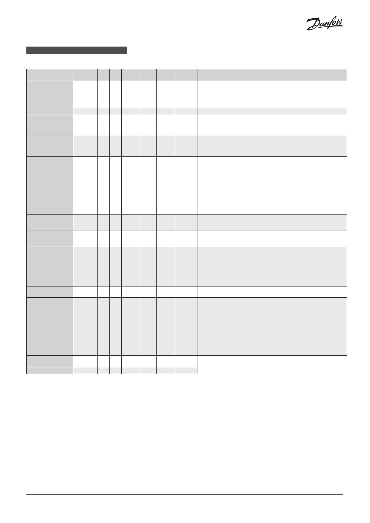
Parameter list
(continued)
Description
In ON/OFF Mode
Closing speed
In Neutralzone/
3 point control
Closing speed = 10
Manual set point ¡15 0 100 0 - No When ¡01= 2, ¡15 determine the start up value
Encoder operation ¡16 0 1 1
Forced closing when
ICM valve Opening
Degree < 3%
Action when ICAD is
losing step
See Note 1
Delay after boost,
before A9 alarm
See Note 1
Max offset value
See Note 1
Define how to Reset/
Suppress A9 alarm
See Note 1
Reset delay for A9
See Note 1
Valve configuration ¡26 0 9 0
Running current
factor
Holding current factor ¡31 0 20 10
ICAD
parameter
Min Max
¡14 0 100 50/100
¡17 0 1 0
¡18 0 6 6
¡19 0 30 1
¡20 3 15 3
¡21 0 4 1
¡22 1 20 5
¡30 0 20 10
Factory
Stored Unit Password Comments
Setting
- No
- Ye s
- No
- No
Minutes No Time delay between two boosts. Linked to ¡18 function
% Ye s
- No
Minutes No
- Ye s
- Ye s
- Ye s
See ¡04. Not applicable to CVE
If ¡26= 1 - 3 then factory setting = 100
If ¡26= 4 - 10 then factory setting = 50
NB: Password protected. Password = 7
0: Encoder disabled. Means ICAD operation as ICAD 600A/ICAD 600A-TS/1200A
without encoder.
1: Encoder enabled
Enable/Disable forced closing. Not applicable to CVE
0: When ICM valve Opening Degree < 3% it will be forced to close regardless of
requested ICM valve Opening Degree
1: When ICM valve Opening Degree < 3% no forced to closing will take place
Action when ICAD is losing step.
0: A boost starts if lost step is detected. After 15 sec, the A9 alarm is flashing and
DO A Common Alarm is ON.
A second boost starts after the time in ¡19 has elapsed. If the second boost cyklus
does not bring the valve back in operation a forced calibration is carried out.
3: A9 alarm flashing after 15 sec. DO A Common Alarm ON. ICAD is locked in
actual position.
No boost cyklus, Reset by Power OFF/ON, regardless of setting ¡21
6: Boost cyklus starts if lost step is detected.
After 3 boost cyklus the A9 alarm is flashing and DO A Common Alarm is ON.
Time interval between boost is set in ¡19.
The boost cyklus continues until the valve is back in operation.
Password=13.
Offset value (numeric)=Requested Opening Degree [%] from Analog Input Opening Degree [%] from encoder (Used with ¡21)
Define how to Reset/Suppress A9 alarm. A9 alarm means A9 flashing in display
and DO Common Alarm ON
0: Reset by Power OFF/ON
1: Autoreset when ICAD have succeeded to come back into normal operation.
Normal operation defined as: Offset value < ¡20 (Max offset value) and ¡22
(delay) has elapsed.
2: A9 alarm is suppressed, meaning no A9 flashing in display and DO Common
Alarm remains OFF
Reset delay for A9. Use when ¡21= 1
OBSERVE: ¡22 is recommended always to be bigger than ¡19 (¡22>¡19)
NB: Password protected. Password = 11
0: No valve selected. Alarm A1 will become active
1: ICM 20 with ICAD 600A / ICMTS 20 with ICAD 600A-TS
2: ICM 25 with ICAD 600A
3: ICM 32 with ICAD 600A
4: ICM 40 with ICAD 1200A
5: ICM 50 with ICAD 1200A
6: ICM 65 with ICAD 1200A
7: ICM 100 with ICAD 1200A
8: ICM 125 with ICAD 1200A
9: ICM 150 with ICAD 1200A
10: CVE pilot with ICAD 1200A
Password=19. Mandatory to set, if ICM/ICADs are installed/serviced, with cold
liquid (-30 °C (-22 °F) or lower) passing through ICM valve.
See also document number AN285243155312
Note 1:
After a parameter change, it is necessary to carry out a Power OFF/ON
6 | AN19798642980802-000802
to be continued....
© Danfoss | Climate solutions | 2021.11
Page 7

ENGLISH
Service
Description
OD % ¡50 0 100 - % - ICM valve Opening Degree / CVE pressure setting
AI [mA] ¡51 0 100 - mA - AI signal
AI [V] ¡52 0 100 - V - AI signal
AO [mA] ¡53 0 100 - mA - A0 signal
DI ¡54 0 1 - - -
DO Close ¡55 0 1 - - - DO Closed status. ON when OD < 3 %
DO Open ¡56 0 1 - - - DO Open status. ON when OD > 97 %
DO Alarm ¡57 0 1 - - - DO alarm status. ON when a Alarm is detected
Display mP SW ver. ¡58 0 100 - - - Software version for display microprocessor
Motor mP SW ver. ¡59 0 100 - - - Software version for motor microprocessor
ICAD
parameter
Min Max
Factory
Setting
Stored Unit Password Comments
DI signals. Depending of ¡02
If ¡02 = 2, one digits are shown. See fig. 8
0 : DI1 = OFF
1 : DI1 = ON
If ¡02 = 3, two digits are shown. See fig. 9
00 : DI1 = OFF, DI2 = OFF
10 : DI1 = ON, DI2 = OFF
01 : DI1 = OFF, DI2 = ON
11 : DI1 = ON, DI2 = ON
Reset to factory setting:
1. Remove the power supply.
2. Activate down arrow and up arrow push buttons at the same time.
3. Connect the power supply.
4. Release down arrow and up arrow push buttons.
5. When the display on ICAD (fig. 2) is alternating between showing: CA and A1 the
factory resetting is complete.
© Danfoss | Climate solutions | 2021.11
AN19798642980802-000802 | 7
Page 8
DEUTSCH
Installation
Den ICAD nicht vor dem Schweißen installieren.
Dies gilt für die elektrische und die mechanische
Installation. Bitte beachten: Sobald der ICAD an
24 VDC angeschlossen ist "brummt" der Motor !
Dies hat keinen Einfluss auf die Funktion
bzw. den
Betrieb des ICAD.
HINWEIS!
Falls die Medientemperatur unter
-30 °C (-22 °F) liegt, müssen Parameter
¡30 und ¡31 eingestellt werden.
Siehe separates Dokument in der
ICAD-Box: Dokument Nummer
AN285243155312
Verwendung
ICAD 600A, ICAD 600A-TS und ICAD 1200A
können zusammen mit folgenden DanfossVentilen verwendet werden (Abb. 1, 5a und 5b).
ICAD 600A ICAD 600A-TS ICAD 1200A
ICM 20 ICMTS 20 ICM 40
ICM 25 ICM 50
ICM 32 ICM 65
ICM 100
ICM 125
ICM 150
CVE-Pilotventil
Elektrische Daten
Die Versorgungsspannung ist galvanisch vom
Ein-/Ausgang getrennt.
Versorgungsspannung
24 V DC (Toleranzen; siehe Tabelle unten)
Last ICAD 600A, ICAD 600A-TS: 1,2 A
ICAD 1200A: 2,0 A
NUR 24 V DC
Bitte den Spannungsabfall im Kabel
beachten.
Durch den Abstand zwischen
eingesetztem GleichstromTransformator und ICAD-Anschlusskasten
wird ein Spannungsabfall auftreten. Der
Kabelquerschnitt und die Größe des
Gleichstrom-Transformators müssen so
berechnet werden, dass die Spannung am
ICAD-Anschlusskasten*, immer, d. h. bei einem
Stillstand und während des ICAD-Betriebs,
innerhalb dieses Bereichs liegt:
1,5 m
3 m
10 m
Vorgefertigte ICAD-Kabellänge
Bestell-Nr.
Spannung ICAD-Klemme
(600A/1200A) [V DC]
* Die Messu ng nicht im ICAD durc hführen.
027H0426
Min. 21 22 23 24
Max. 26,4
027H0438
027H0427
15 m
027H0435
Eigensichere Stromversorgung
24 V DC (Toleranzen; siehe Tabelle oben)
Last ICAD 600A, ICAD 600A-TS: 1,2 A
ICAD 1200A: 2,0 A
Analoger Eingang – Strom oder Spannung
Strom
0/4–20 mA
Wiederstand: 200 W
Spannung
0/2–10 V DC
Wiederstand: 10 kW
Analoger Ausgang
0/4–20 mA
Wiederstand: ≤ 250 W
Digitaler Eingang – EIN/AUS-Eingang mit
potenzialfreien Kontakten (Signal-/Telecom-Relais
mit vergoldeten Kontakten werden empfohlen)
– verwendeter Spannungseingang
EIN: Kontaktwiderstand < 50 W
AUS: Kontaktwiderstand > 100 kW
Digitaler Ausgang – 3 Stk. NPN-Transistorausgang
Externe Versorgung: 5 – 24 V DC (Gleiche
Versorgung wie für den
ICAD kann verwendet werden.
Bitte beachten, dass dann das
galvanisch getrennte System
zerstört wird.)
Wiederstand
: 50 W
Leistung: Max. 50 mA
Umgebungstemperaturbereich
-30 °C/+50 °C (-22 °F/122 °F)
Schutzart
IP67 (~NEMA 6)
Elektrischer Anschluss
Der Anschluss an den ICAD erfolgt über M12Stecker. Der ICAD verfügt über zwei integrierte
M12-Stecker:
Versorgungsspannung: 4-poliger M12-Stecker
Steuersignale: 8-poliger M12-Stecker
Wenn der ICAD mit Kabeln bestellt wird beträgt
die Kabellänge automatisch 1,5m! Wird eine
andere Kabellänge benötigt wird der ICAD ohne
Kabel (mit Steckern) bestellt und das gewünschte
Kabel wird zusätzlich als Zubehör ausgewählt!wird
(1,5 m) M12-Steckbuchsen: (Kabelsatz mit M12Steckbuchsen ist in anderen Längen verfügbar)
Versorgungsspannungskabel mit 4-poligen M12Steckbuchsen
3 x 0,34 mm2 (3 x ~22 AWG) (Abb. 6)
I: Schwarz (+) 19–24 V DC eigensichere
Stromversorgung (optional).
II: Weiß (+) 24 V DC
III: Braun (-) 24 V DC
Regelkabel mit 8-poligen M12-Steckbuchsen
7 x 0,25 mm2 (7 x ~24 AWG) (Abb. 7)
A: Schwarz (-) Digitaler Ausgang
Sammelalarm
B: Braun (-) Digitaler Ausgang
ICM voll geöffnet
C: Rot (-) Digitaler Ausgang
ICM geschlossen
D: Orange (-) Masse
E: Gelb (+) Analoger Eingang
0/4–20 mA *)
F: Grün (+) Analoger Eingang 0/2–10
V/DI1 – Digitaler EIN/AUS-
Eingang
G: Blau (+) Analoger Ausgang
0/4–20 mA *)
*) Wurde die Neutralzone bzw. 3-Punkt-
Regelung gewählt (Parameter i02 = 3),
dann dienen E und G als DI2 – Digitaler
EIN/AUS-Eingang. Siehe Abb. 9.
Elektrische Installation
Allgemeine Vorgehensweise, wenn der ICAD 600A/
ICAD 600 A-TS/1200A auf allen ICM-, ICMTS- und
CVE-Ventilen installiert wird.
Alle erforderlichen elektrischen Anschlüsse
vornehmen.
ICM-Ventil: Analoger oder digitaler Betrieb
ICMTS-/CVE-Ventil: Nur analoger Betrieb
Abb. 6
Modulierende Regelung. Das Ventil wird über
Danfoss-Regler vom Typ EKC/EKE (Abb. 7) oder
über Steuergeräte von Drittanbietern
(z. B. SPS) geregelt.
Analoge Eingangssignale anschließen.
Strom (mA) oder Spannung (V). Siehe
Parameterliste für die Konfiguration der
analogen Eingangssignale.
Gelb (+) und Orange (Masse) werden für
den Stromeingang (mA) verwendet.
oder
Grün (+) und Orange (Masse) werden für
den Spannungseingang (V) verwendet.
Blau (+) und Orange (Masse) werden für
den Stromausgang (mA) verwendet
(optional, nicht verpflichtend).
Abb. 6
Digitaler Betrieb – 7 verdrahtete Kabel (A–G)
EIN/AUS-Betrieb mittels ICM-Motorventil. Das
ICM-Ventil wird mithilfe eines digitalen
potenzialfreien Kontakts geregelt.
Digitale Eingangssignale anschließen (Abb. 8)
Siehe Parameterliste für die Konfiguration
der digitalen Eingangssignale.
Grün (+) und Orange (Masse) sind an einen
potenzialfreien Kontakt angeschlossen.
Digitale Ausgangssignale sind optional, nicht
zwingend erforderlich.
Schwarz (-) und Orange (Masse) sind an ein
Hilfsrelais für einen Sammelalarm
angeschlossen.
Braun (-) und Orange (Masse) sind an ein
Hilfsrelais angeschlossen, das aktiviert wird
wenn das ICM voll geöffnet ist.
Rot (-) und Orange (Masse) sind an ein
Hilfsrelais angeschlossen, das aktiviert wird
wenn das ICM voll geschlossen ist.
Versorgungsspannung – 3 adriges Kabel
(I, II, III) Der ICAD ist an eine normale
Gleichspannungsversorgung von 24 V
anzuschließen. Optional ist eine eigensichere
Stromversorgung über eine Batterie oder
USV (unterbrechungsfreie Stromversorgung)
Wird der ICAD wie unten beschrieben unter
Spannung gesetzt, ist er für die Konfiguration
bereit. Siehe Parameterliste.
Die ICAD-Konfiguration erfolgt unabhängig
davon, ob der ICAD auf dem Ventil installiert
wurde oder nicht.
Siehe Mechanische Installation.
Weiß (+) und Braun (-) an eine
Versorgungsspannung von 24 V DC
anschließen (Abb. 6).
Eine eigensichere Stromversorgung ist optional
(nicht zwingend erforderlich).
Schwarz (+) und Braun (-) an eine eigensichere
Stromversorgung anschließen.
Mechanische Installation
Allgemeine Vorgehensweise, wenn der ICAD
600A/ICAD 600 A-TS/1200A auf allen Ventilen
installiert wird (Abb. 3).
Einen 2,5-mm-Imbuschlüssel gegen den
Uhrzeigersinn drehen und überprüfen, ob die
drei Sockelschrauben vollständig gelöst sind.
Den ICAD langsam oben auf das Ventil
setzen.
Die Magnetkupplung wird das ICM und den
ICAD miteinander verbinden und in Position
bringen.
Den ICAD so positionieren, dass er einfach
bedient werden kann..
Das ICM und den ICAD mittels der drei
Sockelschrauben und einem 2,5-mmImbuskantschlüssel fixieren
Durch etwaiges Lösen der
Deckelschrauben wird die spezielle
Feuchtigkeitabdichtung zerstört!!!
spezielle Feuchtigkeitsdichtung wird
beschädigt, wenn die Schrauben
entfernt werden (Abb. 3, Pos. A)
Neutralzone/3-Punkt-Regelung (Abb. 9 – nur
ICM)¡02 = 3
Wenn ¡02 = 3, wird sowohl die Öffnungs- wie
auch die Schliessgeschwindigkeit automatisch
auf 10 gesetzt!
Sollten sich diese Werte als zu hoch oder niedrig
erweisen können die Werte im Parameter
i04(Öffnen) und ¡14 (Schliessen) angepasst
werden! ist Geschwindigkeit definiert.
¡13 = 1 (Inversbetrieb) ist aktiv.
¡16 = 1 (aktivierter EncoderBetrieb).
¡13 = 0 Normalbetrieb
DI1 = DI2 = AUS
ICAD/ICM behalten derzeitige Position bei
DI1 = DI2 = EIN
ICAD/ICM behalten derzeitige Position bei
DI1 = EIN, DI2 = AUS
ICAD vergrößert Öffnungsgrad
DI1 = AUS, DI2 = EIN
ICAD verringert Öffnungsgrad
¡13 = 1 (Inversbetrieb)
DI1 = DI2 = AUS
ICAD behält derzeitige Position bei
DI1 = DI2 = EIN
ICAD behält derzeitige Position bei
DI1 = EIN, DI2 = AUS
ICAD verringert Öffnungsgrad
.
DI1 = AUS, DI2 = EIN
ICAD vergrößert Öffnungsgrad
* Externe Spannung (External voltage)
** Versorgung (Supply)
*** Regelung (Control)
8 | AN19798642980802-000802
© Danfoss | Climate solutions | 2021.11
Page 9

DEUTSCH
Inbetriebnahme
Wird zum ersten Mal Spannung angelegt, zeigt
das Display auf dem ICAD (Abb. 2) abwechselnd
den aktuellen Öffnungsgrad und A1 an.
Erlaubt es, einen Wert zu verändern, nachdem
die Parameterliste aufgerufen wurde.
Bestätigt und speichert die Wertänderung
eines Parameters.
Zum Verlassen der Parameterliste und
zum Zurückkehren zum Display des
Öffnungsgrads (OD), die Drucktaste zwei
Sekunden lang gedrückt halten.
Drucktaste „Pfeil nach oben“ (Abb. 2, Pos. 3)
Erhöht die Parameternummer bei jeder
Aktivierung um 1.
Display (Abb. 2, Pos. 4)
In der Regel wird der Öffnungsgrad (OD)
des Ventils angezeigt (0 bis 100 %). Wenn
die Drucktasten 20 Sekunden lang nicht
betätigt werden, zeigt das Display den OD
an. Siehe unten:
High bedeutet, dass der ICAD das ICMVentil wie ein EIN/AUS-Magnetventil mit
hoher Drehzahl gemäß einem digitalen
Eingangssignal betreibt. Siehe unten:
Alarme
Der ICAD kann verschiedene Alarme auslösen
und anzeigen.
Wurde ein Alarm erkannt, zeigt das Display am
ICAD (Abb. 2) abwechselnd den aktuellen Alarm
und den derzeitigen Öffnungsgrad an.
A1 weist auf einen Alarm hin, der bedeutet: Kein
Ventil ausgewählt. Siehe Alarme für weitere
Informationen.
Wurde bei Parameter ¡26 das richtige Ventil
(siehe Parameterliste) angegeben, ist zu
beachten, dass eine automatische Kalibrierung
durchgeführt wird. Es ist nicht notwendig, eine
weitere Kalibrierung bei Parameter ¡05
durchzuführen.
Während der Kalibrierung blinkt „CA“ im Display auf.
Der ICAD wird jedes Mal, wenn sich das Ventil
schließt und 0 % erreicht, kurz „CS“ anzeigen.
Allgemeine Bedienung
Der ICAD ist mit einer MMI
(Benutzerschnittstelle) ausgerüstet, mit der
verschiedene Parameter angezeigt und
verändert werden können, um den ICAD und
das entsprechende Ventil an die vorliegende
Kälteanwendung anzupassen. Die Einstellung
der Parameter erfolgt mithilfe der integrierten
ICAD-MMI (Abb. 2). Sie besteht aus:
1 2 3
Drucktaste „Pfeil nach unten“
(Abb. 2, Pos. 1)
reduziert die Parameternummer bei jeder
Aktivierung um 1.
Drucktaste „Enter“ (Abb. 2, Pos. 2)
Erlaubt Zugriff auf die Parameterliste,
indem sie zwei Sekunden lang gedrückt
wird. Eine Parameterliste ist unten
abgebildet (Parameter ¡08):
Sind zur gleichen Zeit mehrere Alarme aktiv,
erscheint nur der Alarm mit der höchsten Priorität.
A1 hat die höchste, A9 die niedrigste Priorität.
Jeder aktive Alarm aktiviert den digitalen
Zeigt den Parameter.
Zeigt den aktuellen Wert eines Parameters.
Sammelalarmausgang (stromlos geöffnet).
Alle Alarme führen einen automatischen Reset
durch, wenn sie ausgeschaltet werden.
Zeigt den Status mittels Text (Abb. 2, Pos. 4).
Alte Alarme (Alarme, die aktiv waren, aber
Mod bedeutet, dass der ICAD das ICM-,
ICMTS- oder CVE-Ventil gemäß einem
wieder ausgeschaltet wurden) können unter
Parameter ¡11 eingesehen werden.
analogen Eingangssignal (Strom oder
Spannung) positioniert.
Entsorgungshinweis
Das Produkt enthält
Low bedeutet, dass der ICAD das ICM-Ventil
wie ein EIN/AUS-Magnetventil mit geringer
Drehzahl gemäß einem digitalen
Eingangssignal betreibt.
Med bedeutet, dass der ICAD das ICMVentil wie ein EIN/AUS-Magnetventil mit
mittlerer Drehzahl gemäß einem digitalen
Geräte müssen gemäß den örtlichen und derzeitig
gültigen Vorschriften separat mit Elektro- und
Elektronikschrott gesammelt werden.
elektrische Komponenten
und darf nicht zusammen
mit Hausmüll entsorgt
werden.
Eingangssignal betreibt.
Beschreibung ICAD-
Kein Ventiltyp ausgewählt A1 Alarm EIN
Reglerstörung A2 Alarm EIN Interne Störung in der Elektronik
Fehler am analogen
Eingang (AI)
Niedrige Spannung
der eigensicheren
Stromversorgung
Stromversorgung des
ICAD überprüfen
Erweiterte Kalibrierung
fehlgeschlagen
Innentemperaturalarm A7 Alarm EIN Temperatur für Schrittmotorkomponente ist zu hoch.
POM-Modus
(Preventive Operational
Mode, vorbeugender
Betriebsmodus)
Alarmtext
Definition
des Zustands
A3 Alarm EIN
A4 Alarm EIN Wenn 5 V < eigensichere Stromversorgung
A5 Alarm EIN Wenn Versorgungsspannung < 18 V
A6 Alarm EIN Ausgewählten Ventiltyp überprüfen.
A8 Alarm EIN Temperatur für Schrittmotorkomponente ist zu hoch.
A9 Siehe
Anmerkungen
Bei der Inbetriebnahme wird A1 angezeigt.
Vorgehensweise:
1) Stromversorgung aus- und wieder einschalten.
Wenn A2 immer noch aktiv ist:
2) Reset auf die Werkseinstellung durchführen.
Wenn A2 immer noch aktiv ist: Den ICAD bei Danfoss
umtauschen.
Nicht aktiv, wenn ¡01 = 2 oder ¡02 = 2
Wenn ¡03 = 1 und AI A > 22 mA
Wenn ¡03 = 2 und AI A > 22 mA
oder AI A < 2 mA
Wenn ¡03 = 3 und AI A > 12 V
Wenn ¡03 = 4 und AI A > 12 V
oder AI A < 1 V
< 18 V, durch
Sicherstellen, dass sich im Ventil keine Fremdkörper befinden..
Entlüften bzw. Umgebungstemperatur des ICAD verringern.
Entlüften bzw. Umgebungstemperatur des ICAD verringern.
Nur aktiv, wenn ¡16 = 1
¡18
Falls das Drehmoment vom ICM-Ventil auf den ICAD zu hoch ist
und
(erhöhte Reibung/klebende Oberflächen), wechselt der ICAD
¡21
automatisch in den POM-Modus, um die verlorene Stufe zu
überwinden.
(Siehe ¡18 und ¡21)
¡08
aktiviert
9 | AN19798642980802-000802
© Danfoss | Climate solutions | 2021.11
Page 10

DEUTSCH
Parameterliste – gilt ab: (¡58:14, ¡59:45) und weiter
Der erste Parameter, der eingegeben werden muss, ist ¡26.
Beschreibung ICAD-
OD (Öffnungsgrad) – 0 100 % – Der Ventilöffnungsgrad des ICM-/ICMTS-Ventils (CVE-Druckeinstellung) wird
Hauptschalter ¡01 1 2 1
Modus ¡02 1 2 1
AI-Signal ¡03 1 4 2
Drehzahl
Im
Modulationsmodus
Öffnen/Schließen
Drehzahl
Im EIN/AUS-Modus
Öffnungsdrehzahl
In Neutralzone/
3-Punkt-Regelung
Öffnungsdrehzahl
= 10
Automatische
Kalibrierung
AO-Signal ¡06 0 2 2
Eigensichere
Stromversorgung
Eigensichere
Stromversorgung
DI-Funktion ¡09 1 2 1
Passwort ¡10 0 199 0 – – Nummer eingeben, um auf passwortgeschützte Parameter zuzugreifen: ¡26
Alte Alarme ¡11 A1 A99 – – Nein Alte Alarme werden aufgelistet, wobei der zuletzt ausgelöste oben steht. Die
Öffnungsgrad bei
Stromausfall
Inversbetrieb ¡13 0 1 0
Parameter
Min. Max. Werksein-
¡04 1 100 50/100
¡05 0 2 0 – Nein Nicht aktiv, bevor nicht ¡26 parametriert wurde.
¡07 1 4 1
¡08 0 1 0
¡12 0 100 50
stellung
Gespeic-
hert
Einheit Pass-
– Nein Interner Hauptschalter
– Nein Betriebsmodus
– Nein Art des AI-Signals vom externen Regler
– Nein Die Geschwindigkeit kann verringert werden. Die max. Geschwindigkeit ist 100 %
– Nein Art des A0-Signals für die ICM-Ventilposition
– Nein Soll-Zustand bei Stromausfall definieren Bedingung: eigensichere
Anmerkungen
wort
während des normalen Betriebs angezeigt.
Laufender Display-Wert (siehe ¡01, ¡05)
1: Normaler Betrieb
2: Handbedienung. Der Ventilöffnungsgrad blinkt auf. Mit den Drucktasten „Pfeil
nach unten“ und „Pfeil nach oben“ kann der OD manuell eingegeben werden.
1: Modulation – Positionierung des ICM, ICMTS und CVE gemäß dem analogen
Eingang (siehe ¡03).
2: EIN/AUS – nur ICM. Das ICM-Ventil wird wie ein EIN/AUS-Magnetventil
betrieben und über den digitalen Eingang geregelt. Siehe auch ¡09.
3: Neutralzone/3-Punkt-Regelung – nur ICM. Vergrößern/Verringern des
Öffnungsgrads über den digitalen Eingang. Siehe Abb. 9.
1: 0 – 20 mA
2: 4 – 20 mA
3: 0 – 10 V
4: 2 – 10 V
– nicht aktiv im Handbetrieb (¡01 = 2).
Beim CVE sollte die Geschwindigkeit nicht höher sein als 50 (Werkseinstellung).
Wenn ¡26 = 1–3, dann Werkseinstellung = 100
Wenn ¡26 = 4–10, dann Werkseinstellung = 50
Wenn sich das Ventil öffnet und ¡04 ≤ 33 oder sich das Ventil schließt und ¡14 ≤ 33
=> „Low“ wird angezeigt.
Wenn sich das Ventil öffnet und 33 < falls ¡04 ≤ 66 oder sich das Ventil schließt und 33 <
falls ¡14 ≤ 66
=> „Med“ wird angezeigt.
Wenn sich das Ventil öffnet und ¡04 ≥ 67 oder sich das Ventil schließt und ¡14 ≥ 67
=> „High“ wird angezeigt.
Anzeige wird immer automatisch auf 0 zurück gesetzt!
Während der Kalibrierung blinkt „CS“ im Display auf, wenn die Drucktaste „Enter“
zwei Sekunden lang gedrückt wurde.
0: Keine Kalibrierung
1: Normal erzwungene Kalibrierung – „CS“ blinkt langsam
2: Erweiterte Kalibrierung – „CS“ blinkt schnell
0: Kein Signal
1: 0–20 mA
2: 4–20 mA
Stromversorgung wird vorhanden.
1: Ventil schließen
2: Ventil öffnen
3: Ventilposition beibehalten
4: Den durch ¡12 gegebenen OD umsetzen.
Ja Eigensichere Stromversorgung ist angeschlossen und ermöglicht A4-Alarm:
0: Nein
1: Ja
Nein Funktion definieren, wenn DI auf EIN gestellt ist (kurzgeschlossene DI-Klemmen)
und ¡02 = 2
1: ICM-Ventil öffnen (DI = AUS = > ICM-Ventil schließen)
2: ICM-Ventil schließen (DI = AUS = > ICM-Ventil öffnen)
Passwort = 11
Alarmliste kann zurückgesetzt werden, indem die Drucktasten „Pfeil nach unten“
und „Pfeil nach oben“ gleichzeitig zwei Sekunden lang gedrückt werden.
Nein Nur aktiv, wenn ¡07 = 4
Ist eine eigensichere Stromversorgung angeschlossen und tritt ein Stromausfall ein,
öffnet sich das Ventil um den angegebenen OD.
Nein Wenn ¡02 = 1
0: Erhöhen des analogen Eingangssignals => Vergrößern des ICM-Öffnungsgrads
1: Erhöhen des analogen Eingangssignals => Verringern des ICM-Öffnungsgrads
Wenn ¡02 = 3
0: DI1 = EIN, DI2 = AUS => Vergrößerung des Ventilöffnungsgrads
DI1 = AUS, DI2 = EIN => Verringerung des Ventilöffnungsgrads
DI1 = DI2 = AUS => ICAD/ICM behalten derzeitige Position bei
DI1 = DI2 = EIN => ICAD/ICM behalten derzeitige Position bei
1: DI1 = EIN, DI2 = AUS => Verringerung des ICM-Öffnungsgrads
DI1 = AUS, DI2 = EIN => Vergrößerung des ICM-Öffnungsgrads
DI1 = DI2 = AUS => ICAD/ICM behalten derzeitige Position bei
DI1 = DI2 = EIN => ICAD/ICM behalten derzeitige Position bei
Fortsetzung nächste Seite
© Danfoss | Climate solutions | 2021.11
AN19798642980802-000802 | 10
Page 11

Parameterliste
(Fortsetzung)
DEUTSCH
Beschreibung ICAD-
Im EIN/AUS-Modus
Schließdrehzahl
In Neutralzone/
3-Punkt-Regelung
Schließdrehzahl
= 10
Manueller Sollwert ¡15 0 100 0 – Nein Wenn ¡01 = 2, bestimmt ¡15 den Startwert.
Encoder-Betrieb ¡16 0 1 1
Zwangsschließung,
wenn ICMVentilöffnungsgrad
< 3 %
Maßnahme, wenn
ICAD eine
Stufe verliert,
siehe Hinweis 1
Verzögerung nach
Boost
vor A9-Alarm
Siehe Hinweis 1
Offsetwert max.
Siehe Hinweis 1
Definieren des
Zurücksetzens/
Suppress
(Rücksetzen/
Abstellen) des A9Alarms
Siehe Hinweis 1
Rücksetzverzögerung für A9
Siehe Hinweis 1
Ventilkonfiguration ¡26 0 9 0
Betriebsstrom
Faktor
Faktor Haltestrom ¡31 0 20 10
Parameter
Min. Max. Werksein-
stellung
¡14 0 100 50/100
¡17 0 1 0
¡18 0 6 6
¡19 0 30 1
¡20 3 15 3
¡21 0 4 1
¡22 1 20 5
¡30 0 20 10
Gespeic-
hert
Einheit Passwort Anmerkungen
– Nein Siehe ¡04. Gilt nicht für das CVE.
– Ja Anmerkung: Passwortgeschützt. Passwort = 7
– Nein Aktivieren/Deaktivieren der Zwangsschließung. Gilt nicht für das CVE.
– Nein Maßnahme, wenn ICAD eine Stufe verliert.
Minuten Nein Verzögerungszeit zwischen zwei Boosts. Verknüpft mit Funktion ¡18.
% Ja Passwort=13.
– Nein Definieren des Zurücksetzens/Suppress (Rücksetzen/Abstellen) des A9-
Minuten Nein Rücksetzverzögerung für A9. Verwenden, wenn ¡21=1
– Ja Anmerkung: Passwortgeschützt. Passwort = 11
– Ja Passwort=19. Einstellung zwingend erforderlich, wenn ICM/ICADs mit kalter
– Ja
Wenn ¡26 = 1–3, dann Werkseinstellung = 100
Wenn ¡26 = 4–10, dann Werkseinstellung = 50
0: Encoder deaktiviert. Das bedeutet, der ICAD wird als ICAD 600A/ICAD 600
A-TS/1200A ohne Encoder betrieben.
1: Encoder aktiviert.
0: Wenn der ICM-Ventilöffnungsgrad unter 3 % liegt, wird ungeachtet des
erwünschten ICM-Ventilöffnungsgrads eine Zwangsschließung durchgeführt.
1: Wenn der ICM-Ventilöffnungsgrad unter 3 % liegt, erfolgt keine Schließung.
0: Boost startet, wenn eine verlorene Stufe erkannt wird. Nach 15 Sek. blinkt
der A9-Alarm und DO A Common Alarm (Sammelalarm) ist EIN.
Zweiter Boost startet, sobald die Zeit in ¡19 abgelaufen ist. Falls der zweite
Boost-Zyklus das Ventil nicht wieder in Betrieb setzt, wird eine erzwungene
Kalibrierung durchgeführt.
3: A9-Alarm blinkt nach 15 Sek. DO A Common Alarm (Sammelalarm) EIN.
ICAD wird in aktueller Position verriegelt.
Kein Boost-Zyklus, Zurücksetzen durch Strom AUS/EIN, unabhängig von
Einstellung ¡21
6: Boost-Zyklus startet, wenn eine verlorene Stufe erkannt wird.
Nach drei Boost-Zyklen blinkt der A9-Alarm und DO A Common Alarm
(Sammelalarm) ist EIN.
Das Zeitintervall zwischen den Boosts wird in ¡19eingestellt.
Der Boost-Zyklus wird solange fortgesetzt, bis das Ventil wieder in Betrieb ist.
Offsetwert (numerisch)=gewünschter Öffnungsgrad [%] vom Analogeingang
- Öffnungsgrad [%] vom Kodierer (verwendet mit ¡21)
Alarms. A9-Alarm bedeutet: A9 blinkt im Display und DO Common Alarm
(Sammelalarm) EIN
0: Zurücksetzen durch Strom AUS/EIN
1: Automatisches Zurücksetzen, sobald ICAD wieder im Normalbetrieb läuft.
Normalbetrieb definiert als: Offsetwert < ¡20 (Offsetwert max.) und ¡22
(Verzögerung) ist abgelaufen.
2: A9-Alarm ist abgestellt: A9 blinkt nicht im Display und DO Common
Alarm (Sammelalarm) bleibt AUS
BITTE BEACHTEN: ¡22 sollte stets größer sein als ¡19 (¡22>¡19)
0: Kein Ventil gewählt. Alarm A1 wird aktiviert.
1: ICM 20 mit ICAD 600 A/ICMTS 20 mit ICAD 600A-TS
2: ICM 25 mit ICAD 600A
3: ICM 32 mit ICAD 600A
4: ICM 40 mit ICAD 1200A
5: ICM 50 mit ICAD 1200A
6: ICM 65 mit ICAD 1200A
7: ICM 100 mit ICAD 1200A
8: ICM 125 mit ICAD 1200A
9: ICM 150 mit ICAD 1200A
10: CVE-Pilotventil mit ICAD 1200A
Flüssigkeit (-30 °C (-22 °F) oder niedriger), die durch das ICM-Ventil läuft,
montiert/gewartet werden. Siehe auch Dokument Nummer AN285243155312
Hinweis 1:
Nach einer Parameteränderung muss Strom AUS/EIN geschaltet werden.
11 | AN19798642980802-000802
© Danfoss | Climate solutions | 2021.11
Page 12

Wartung
Beschreibung ICAD
-Parameter
OD % ¡50 0 100 – % – ICM-Ventilöffnungsgrad/CVE-Druckeinstellung
AI [mA] ¡51 0 100 – mA – AI-Signal
AI [V] ¡52 0 100 – V – AI-Signal
AO [mA] ¡53 0 100 – mA – AO-Signal
DI ¡54 0 1 – – – DI-Signale, abhängig von ¡02
DO geschlossen ¡55 0 1 – – – DO-Status „geschlossen“ Nur EIN wenn OD < 3 %
DO offen ¡56 0 1 – – – DO-Status „geöffnet“ Nur EIN wenn OD > 97 %
DO-Alarm ¡57 0 1 – – – DO-Alarmstatus EIN, wenn ein Alarm erkannt wird
Display MP SW-Ver. ¡58 0 100 – – – Softwareversion für Display-Mikroprozessor
Motor MP SW-Ver. ¡59 0 100 – – – Softwareversion für Motor-Mikroprozessor
Min. Max. Werksein-
stellung
Gespeic-
hert
Einheit Passwort Anmerkungen
Wenn ¡02 = 2, wird eine Zahl angezeigt. Siehe Abb. 8.
0 : DI1 = AUS
1 : DI1 = EIN
Wenn ¡02 = 3, werden zwei Zahlen angezeigt. Siehe Abb. 9.
00 : DI1 = AUS, DI2 = AUS
10 : DI1 = EIN, DI2 = AUS
01 : DI1 = AUS, DI2 = EIN
11 : DI1 = EIN, DI2 = EIN
Auf Werkseinstellungen zurücksetzen:
1. Spannungsversorgung abschalten.
2. Drucktasten „Pfeil nach unten“ und „Pfeil nach oben“ gleichzeitig drücken.
3. Spannungsversorgung anschließen.
4. Drucktasten „Pfeil nach unten“ und „Pfeil nach oben“ loslassen.
5. Wenn das ICAD-Display (Abb. 2) abwechselnd CA und A1 anzeigt, sind die
Werkseinstellungen wiederhergestellt.
12 | AN19798642980802-000802
© Danfoss | Climate solutions | 2021.11
Page 13

FRANÇAIS
Installation
N’installez pas l’ICAD avant le soudage. Cela
s’applique pour les connexions électriques et
l’installation mécanique. Notez qu’un ICAD
connecté à une alimentation 24 V c.c. émet un
bruit acoustique lorsqu’il se trouve à l’arrêt.
Cela
n’a pas d’influence sur le
fonctionne
ment/l’actionnement de l’ICAD.
REMARQUE !
Si la température du fluide est
inférieure à - 30 °C (- 22 °F) il est
obligatoire de régler les paramètres
¡30 et ¡31.
Consultez le document séparé joint
dans la boîte ICAD : document numéro
AN285243155312.
Utilisation
Les ICAD 600A, ICAD 600A-TS et ICAD 1200A
peuvent être utilisés avec les vannes Danfoss
suivantes (fig. 1, 5a et 5b).
ICAD 600A ICAD 600A-TS ICAD 1200A
ICM 20 ICMTS 20 ICM 40
ICM 25 ICM 50
ICM 32 ICM 65
ICM 100
ICM 125
ICM 150
Vanne pilote CVE
Données électriques
La tension d’alimentation est isolée galvaniquement
entre l’entrée/la sortie.
Tension d’alimentation
24 V c.c. (Tolérances ; voir tableau ci-dessous)
Charge ICAD 600A, ICAD 600A-TS : 1,2 A
ICAD 1200A : 2,0 A
24 V c.c. UNIQUEMENT
Attention à la chute de tension dû à
la longueur des câbles
La distance entre le transformateur
en CC utilisé et la boîte à bornes de
l’ICAD peut entraîner une chute de tension. La
section des câbles et la taille du transformateur
en CC doivent être calculées de sorte que
la tension au niveau de la boîte à bornes
de l’ICAD*, Aussi bien l’arrêt qu’en cours
de fonctionnement de l’ICAD, soit toujours
comprise dans cette plage :
Longueur de câble prédéfinie
de l’ICAD
N° de code
Tension à la borne de l’ICAD
(600A/1200A) [V c.c.]
* Ne pas effectuer les mesures à l’intérieur de l’ICAD proprement dit
1,5 m
3 m
10 m
027H0426
027H0438
027H0427
Min. 21 22 23 24
Max. 26,4
027H0435
15 m
Alimentation de sécurité
24 V c.c. (Tolérances ; voir le tableau ci-dessus)
Charge ICAD 600A, ICAD 600A-TS : 1,2 A
ICAD 1200A : 2,0 A
Entrée analogique : intensité ou tension
Intensité
0/4 - 20 mA
Charge : 200 W
Tension
0/2 - 10 Vcc
Charge : 10 kW
Sortie analogique
0/4 - 20 mA
Charge : ≤ 250 W
Entrée numérique : entrée numérique TOUT OU RIEN
au moyen de contacts libres de potentiel (relais de
signalisation/télécommunication avec contacts
plaqués or recommandés) – Tension d’entrée utilisée
MARCHE : Impédance de contact < 50 W
ARRÊT : Impédance de contact > 100 kW
Sortie numérique : 3 pces. Sortie de transistor NPN
Alimentation externe : 5 - 24 V c.c. (il est possible
d’utiliser la même
alimentation que pour
l’ICAD mais le système
isolé galvaniquement
Charge de sortie : 50 W
sera alors hors service).
Charge : Max. 50 mA
Plage de température (ambiante)
–30 °C/+50 °C (–22 °F/122 °F)
Boîtier
IP67 (~NEMA 6).
Raccordement électrique
Le raccordement à l’ICAD s’effectue au moyen
de connecteurs M12. L’ICAD comporte deux
connecteurs mâles M12 intégrés :
Alimentation : connecteur mâle M12 4 pôles
Signaux de commande : connecteur mâle
M12 8 pôle
.
Si l’ICAD est fourni avec des câbles (1,5 m (60 in))
Connecteurs femelles M12 : (jeu de câbles avec
connecteurs femelles M12 disponible dans d’autres
longueurs)
Câble d’alimentation avec connecteur
femelle M12 4 pôles
3 x 0,34 mm2 (3 x ~22 AWG) (fig. 6)
I : noir (+) Alimentation de sécurité
19 - 24 Vcc (facultatif).
II : Blanc (+) 24 V c.c.
III : Marron (–) 24 V c.c.
Câble de régulation avec connecteur
femelle M12 8 pôles
7 x 0,25 mm2 (7 x ~24 AWG) (fig. 7)
A : noir (–) Sortie numérique.
Alarme commune.
B : Marron (–) Sortie numérique.
ICM totalement ouverte.
C : rouge (–) Sortie numérique.
ICM totalement fermée.
D : orange (–) GND - Masse
E : Jaune (+) Entrée analogique
0/4-20 mA. *)
F : Vert (+) Entrée analogique 0/2-10 V/
DI1 : entrée numérique (DI)
tout ou rien.
G : Bleu (+) Sortie analogique 0/4-
20 mA. *)
*) Si l’option Zone neutre/régulation 3 points
est sélectionnée (paramètre i02 = 3), E et
G sont utilisées en tant que DI2 : entrée
numérique TOUT OU RIEN. Consultez la
Fig. 9.
Installation électrique
Procédure générale pour les ICAD 600A/ICAD
600A-TS/1200A installés sur toutes les vannes
ICM, ICMTS et CVE.
Toutes les connexions électriques nécessaires
doivent être effectuées.
Vanne ICM : fonctionnement analogique ou
numérique
Vanne CVE/ICMTS : analogique uniquement
Fig. 7
Régulation de modulation. Vanne commandée
à partir du système électronique Danfoss de
type EKC/EKE (fig. 7) ou à partir d’un autre
système électronique (tel que l’API).
Connectez les signaux d’entrée analogique.
Intensité (mA) ou Tension (V). Consultez la
liste des paramètres pour la configuration
des signaux d’entrée analogique.
Les bornes jaune (+) et orange (GND) sont
utilisées pour l’entrée d’intensité (mA).
ou
Les bornes verte (+) et orange (GND) sont
utilisées pour l’entrée de tension (V).
Les bornes bleue (+) et orange (GND) sont
utilisées pour la sortie d’intensité (mA)
(facultatif).
Fig. 8
Fonctionnement numérique : câble à 7 fils (A-G),
fonctionnement tout ou rien de l’électrovanne
ICM. La vanne ICM doit être régulée au moyen
d’un contact numérique libre de potentiel.
Connectez les signaux d’entrée numérique
(Fig. 8). Consultez la liste des paramètres
pour la configuration des signaux d’entrée
numérique.
Les bornes verte (+) et orange (GND) sont
connectées à un contact libre de potentiel.
Les signaux de sortie numérique sont facultatifs.
Les bornes noire (–) et orange (GND) sont
connectées au relais auxiliaire pour l’alarme
commune.
Les bornes marron (–) et orange (GND) sont
connectées à un relais auxiliaire indiquant
que l’ICM est totalement ouverte.
Les bornes rouge (–) et orange (GND) sont
connectées à un relais auxiliaire indiquant
que l’ICM est totalement fermée.
Tension d’alimentation : câble à 3 connexions
(I, II, III). L’ICAD doit être connecté à une
alimentation 24 V c.c. normale. Une alimentation
de sécurité en option est possible au moyen
d’une batterie ou d’une alimentation sans
interruption (onduleur). Lorsque l’ICAD est
placé sous tension comme décrit ci-dessous,
il est prêt à être configuré. Consultez la liste
des paramètres.
La configuration de l’ICAD est possible qu’il
soit installé ou non sur la vanne.
Voir Installation mécanique.
Connectez les bornes blanche (+) et marron
(–) à une tension d’alimentation 24 Vcc (Fig. 6).
Alimentation de sécurité (facultatif).
Connectez les bornes noire (+) et marron
(–) à une alimentation de sécurité.
Installation mécanique
Procédure générale pour les ICAD 600A/ICAD
600A-TS/1200A installés sur toutes les vannes
(fig. 3).
Vérifiez que les trois vis de réglage sont
complètement dévissées (sens antihoraire)
à l’aide d’une clé hexagonale de 2,5 mm.
Montez l’ICAD en l’abaissant lentement sur le
haut de la vanne.
Le couplage magnétique attire l’ICAD sur la
vanne et assure un positionnement correct.
Poussez l’ICAD en place.
Fixez l’ICAD à la vanne à l’aide des trois vis de
réglage, en utilisant une clé hexagonale de
2,5 mm.
La bague d’étanchéité spéciale sera
endommagée si les vis sont retirées
(fig. 3, pos. A)
Zone neutre/régulation 3 points
(fig. 9 - ICM uniquement)
¡02 = 3
Lorsque ¡02 = 3 les réglages d’usine de ¡04
(ouverture) et de ¡14 (fermeture) sont définis
sur 10.
Lorsque ¡02= 3, les vitesses données par ¡04
(ouverture) et ¡14 (fermeture) sont actives.
¡13 (fonctionnement inverse) est actif
¡16 = 1 (activation de l’encodeur) est actif.
¡13 = 0 (fonctionnement direct)
DI1 = DI2 = ARRÊT
Maintien de la position actuelle de l’ICAD/ICM
DI1 = DI2 = MARCHE
Maintien de la position actuelle de l’ICAD/ICM
DI1 = MARCHE, DI2 = ARRÊT
Augmentation du degré d’ouverture de l’ICAD
DI1 = ARRÊT, DI2 = MARCHE
Réduction du degré d’ouverture de l’ICAD
¡13 = 1 (fonctionnement inverse)
DI1 = DI2 = ARRÊT
Maintien de la position actuelle de l’ICAD
DI1 = DI2 = ON
Maintien de la position actuelle de l’ICAD
DI1 = MARCHE, DI2 = ARRÊT
Réduction du degré d’ouverture de l’ICAD
DI1 = ARRÊT, DI2 = MARCHE
Augmentation du degré d’ouverture de l’ICAD
* Tension externe (External voltage)
** Alimentation (Supply)
*** Régulation (Control)
© Danfoss | Climate solutions | 2021.11
AN19798642980802-000802 | 13
Page 14

FRANÇAIS
Démarrage
Lorsque l’ICAD est placé sous tension pour la
première fois, il affiche en alternance (Fig. 2) :
Degré d’ouverture réel et A1.
Permet de modifier une valeur après avoir
accédé à la liste des paramètres.
Permet de valider et d'enregistrer la
modification de la valeur d'un paramètre.
Pour quitter la liste des paramètres et
revenir à l’écran d’affichage du degré
d’ouverture (OD), maintenez le bouton
enfoncé pendant 2 secondes.
Bouton Flèche vers le haut (fig. 2, pos. 3)
Augmente la valeur du paramètre d’une
unité à chaque pression.
Affichage (fig. 2, pos. 4)
Affiche, normalement, le degré d’ouverture
(OD) de 0-100 % de la vanne. En l’absence
de pression sur les boutons pendant 20
secondes, l’écran affiche constamment l’OD,
comme illustré ci-dessous :
High signifie que l’ICAD fait fonctionner la
vanne ICM comme une électrovanne tout
ou rien à haute vitesse en fonction d’un
signal d’entrée digitale. comme illustré cidessous :
Alarms
L’ICAD peut gérer et afficher différentes alarmes.
Si une alarme a été détectée, l'ICAD (Fig. 2)
affiche
alternativement l'alarme réelle et le degré
d'ouverture
actuel.
A1 signale une alarme qui donne les informations
suivantes : aucune vanne sélectionnée. Voir
Alarmes pour plus d’informations.
Notez que lorsque la vanne correcte est entrée
dans le paramètre ¡26 (consultez la liste des
paramètres), un calibrage automatique a lieu.
Aucun autre calibrage n’est nécessaire pour le
paramètre ¡05.
Tout au long de l’étalonnage, la mention CA
clignote à l’écran.
L’ICAD affiche brièvement la mention CS chaque
fois que la vanne va se fermer et atteindre 0 %.
Fonctionnement général
L’ICAD est équipé d’une HMI (interface hommemachine) permettant de consulter et de modifier
différents paramètres pour adapter l’ICAD et la
vanne correspondante à l’application de
réfrigération réelle. Le réglage des paramètres
s’effectue au moyen des boutons suivants de la
HMI intégrée de l’ICAD (fig. 2) :
1 2 3
Bouton Flèche vers le bas
(fig. 2, pos. 1)
Permet d’augmenter le paramètre d’une
unité à chaque pression
Bouton Entrée (fig. 2, pos. 2)
Permet d’accéder à la liste des paramètres
en maintenant le bouton enfoncé pendant
2 secondes. Un exemple de liste des
paramètres est donné ci-dessous
(paramètre ¡08) :
Affiche le paramètre.
Affiche la valeur réelle d’un paramètre.
Affiche l’état en toutes lettres (Fig. 2, pos. 4).
Mod signifie que l’ICAD positionne la vanne
ICM, ICMTS ou CVE en fonction d’un signal
d’entrée analogique (intensité ou tension).
Low signifie que l’ICAD fait fonctionner la
vanne ICM comme une électrovanne tout
ou rien à basse vitesse en fonction d’un
signal d’entrée digitale.
Med signifie que l’ICAD fait fonctionner la
vanne ICM comme une électrovanne tout
ou rien à vitesse moyenne en fonction d’un
signal d’entrée digitale.
du marché Tex te
Aucun type de vanne
sélectionné
Défaut du régulateur A2 Alarme
Erreur d’entrée AI A3 Alarme
Basse tension de
l’alimentation de
sécurité Alimentation
Vérifiez l’alimentation
de l’ICAD
Échec de l’étalonnage
étendu
Alarme de
température interne
Mode POM
(Mode Préventif
Opérationnel)
d’alarme
Définition
ICAD
A1 Alarme
A4 Alarme
A5 Alarme
A6 Alarme
A7 Alarme
A8 Alarme
A9 Voir
d’un
événement
activée
activée
activée
activée
activée
activée
activée
activée
¡18
et
¡21
Si plusieurs alarmes sont actives simultanément,
seule l’alarme de priorité la plus élevée s’affiche.
A1 a la priorité la plus élevée, A9 la plus basse.
Toute alarme active enclenche la sortie d’alarme
numérique Tout ou rien commune (normalement
ouverte).
Toutes les alarmes se réinitialisent automatiquement
lorsqu’elles disparaissent physiquement.
Les anciennes alarmes (celles qui ont été actives
mais ont à nouveau disparu physiquement) sont
disponibles sous le paramètre ¡11.
Remarque sur la mise au rebut
Le produit contient des
composants électriques
et ne peut pas être mis
au rebut avec les ordures
ménagères.
L’équipement doit être trié avec les déchets
électriques et électroniques. La législation
locale en vigueur doit être respectée.
Commentaires
Au démarrage, A1 est affiché
Défaut interne des éléments électroniques.
Mesures :
1) Éteignez et rallumez.
Si A2 est toujours activée.
2) Réinitialisez les réglages d’usine.
Si A2 est toujours activée. renvoyez l’ICAD à Danfoss
Inactive si ¡01 = 2 ou ¡02 = 2
Lorsque ¡03 = 1 et AI A > 22 mA
Lorsque ¡03 = 2 et AI A > 22 mA
ou AI A < 2 mA
Lorsque ¡03 = 3 et AI A > 12 V
Lorsque ¡03 = 4 et AI A > 12 V
ou AI A < 1 V
Si 5 V < alimentation de sécurité
<18 V. Activée par
Si la tension d’alimentation < 18 V
Vérifiez le type de vanne sélectionné
Vérifiez l’absence de corps étrangers à l’intérieur de la vanne.
Température des composants du moteur pas à pas trop élevée.
Ventilez pour diminuer la température ambiante de l’ICAD.
Température des composants du moteur pas à pas trop élevée.
Ventilez pour diminuer la température ambiante de l’ICAD.
Actif seulement si ¡16 = 1
Si l’ICAD fait face à un couple trop élevé de la vanne ICM
(friction/surfaces adhésives accrues), il bascule
automatiquement en mode POM pour surmonter le pas perdu.
(Voir ¡18 et ¡21)
¡08
14 | AN19798642980802-000802
© Danfoss | Climate solutions | 2021.11
Page 15

FRANÇAIS
Liste des paramètres. Valable à par tir de (¡58:14, ¡59:45) et au-delà
Le premier paramètre entré doit être : ¡26
du marché Paramètre
OD (degré d’ouverture) - 0 100 % - Le degré d’ouverture de la vanne ICM/ICMTS (paramètre de pression CVE) s’affiche en mode
Interrupteur principal ¡01 1 2 1
Mode ¡02 1 2 1
Signal d’entrée AI en
tension
Vitesse
En Mode de modulation
Vitesse
d’ouverture/fermeture
En Mode ON/OFF
Vitesse d’ouverture
En zone point mort/
régulation 3 points
Vitesse d’ouverture = 10
Étalonnage
automatique
Signal AO ¡06 0 2 2
Sécurité ¡07 1 4 1
Alimentation de sécurité ¡08 0 1 0
Fonction DI ¡09 1 2 1
Mot de passe ¡10 0 199 0 - - Entrez un chiffre pour accéder aux paramètres protégés par mot de passe : ¡26
Mémorisation des
alarmes
OD lors d’une coupure
de courant.
Fonctionnement inverse ¡13 0 1 0
ICAD
Min. Max. Réglage
¡03 1 4 2
¡04 1 100 50/ 100
¡05 0 2 0 - Non Inactif avant utilisation de ¡26.
¡11 A1 A99 - - Non Les anciennes alarmes seront répertoriées avec la plus récente affichée en premier. La liste
¡12 0 100 50
d’usine
Enregistré Unité Mot de
passe
- Non Sectionneur principal interne
- Non Mode de fonctionnement
- Non Type de signal d’entrée analogique (AI) du contrôleur externe
- Non La vitesse peut être réduite. La vitesse max. est de 100 %. Inactive en mode de
- Non Type de signal A0 pour position de la vanne ICM
- Non Définissez les conditions en cas de coupure de courant ; l’alimentation de sécurité est
oui Alimentation de sécurité raccordée et activation de l’alarme A4 :
Non Définition de la fonction lorsque l’entrée digitale (DI) est sur MARCHE (bornes DI court-
Non Uniquement actif si ¡07 = 4
Non Lorsque ¡02 = 1
Commentaires
de fonctionnement normal.
Valeur affichée pendant le fonctionnement (voir ¡01, ¡05).
1 : fonctionnement normal
2 : fonctionnement manuel. Le degré d’ouverture de la vanne clignotera. Il est possible
de saisir le degré d’ouverture manuellement à l’aide des boutons Flèche vers le haut et
Flèche vers le bas.
1 : Modulation : position de la vanne ICM, l’ICMTS et CVE en fonction de l’entrée analogique
(voir ¡03)
2 : MARCHE/ARRÊT - ICM uniquement. Fonctionnement de la vanne ICM comme
électrovanne MARCHE/ARRÊT régulée par entrée digitale. Voir également ¡09.
3 : Zone neutre/régulation 3 points - ICM uniquement. Augmentation/réduction du degré
d’ouverture par entrée digitale. Voir fig. 9
1 : 0 – 20 mA
2 : 4 – 20 mA
3 : 0 – 10 V
4 : 2 – 10 V
fonctionnement manuel (¡01 = 2)
Pour la vanne CVE, la vitesse ne doit pas dépasser 50 (réglage d’usine)
Si ¡26 = 1 - 3, alors le réglage d’usine = 100
Si ¡26= 4 - 10, alors le réglage d’usine = 50
Si la vanne s’ouvre et (¡04 < = 33) ou si la vanne se ferme et (¡14 < = 33)
=> Low s’affiche à l’écran.
Si la vanne s’ouvre et (33 < si ¡04 < = 66) ou si la vanne se ferme et (33 < si ¡14 < = 66)
=> Med s’affiche à l’écran.
Si la vanne s’ouvre et (¡04 > = 67) ou si la vanne se ferme et (¡14 > = 67)
=> High s’affiche à l’écran.
Réinitialisation automatique toujours à 0.
CA clignote à l’écran pendant le calibrage si le bouton Entrée a été enfoncé pendant deux
secondes.
0 : aucun calibrage
1 : calibrage forcé normal - CA clignote lentement
2 : Étalonnage étendu – CA clignote rapidement
0 : aucun signal
1 : 0 – 20 mA
2 : 4 – 20 mA
installée.
1 : fermer la vanne
2 : ouvrir la vanne
3 : maintenir la vanne en position
4 : passer au degré d’ouverture donné par ¡12"
0 : Non
1 : oui
circuitées) lorsque ¡02 = 2
1 : Ouvrir la vanne ICM (DI = ARRÊT => Fermer la vanne ICM)
2 : Fermer la vanne ICM (DI-entrée numérique = OFF-Arrêt => Ouvrir la vanne ICM)
Mot de passe = 11
d’alarmes peut être réinitialisée en enfonçant simultanément les flèches bas et haut pendant
2 secondes.
Si l’alimentation de sécurité est raccordée et si une coupure de courant survient, la vanne passe au
degré d’ouverture spécifié.
0 : Augmentation du signal d’entrée analogique => Augmentation du degré d’ouverture de
l’ICMTS
1 : Réduction du signal d’entrée analogique => Réduction du degré d’ouverture de l’ICMTS
Lorsque ¡02 = 3
0 : DI1 = MARCHE, DI2 = ARRÊT => Augmentation du degré d’ouverture de la vanne.
DI1 = ARRÊT, DI2 = MARCHE => Réduction du degré d’ouverture de la vanne
DI1 = DI2 = ARRÊT => Maintien de la position actuelle de l’ICAD/ICMTS
DI1 = DI2 = MARCHE => Maintien de la position actuelle de l’ICAD/ICMTS
1 : DI1 = MARCHE, DI2 = ARRÊT =>Réduc tion du degré d’ouverture de l’ICMTS
DI1 = ARRÊT, DI2 = MARCHE => Augmentation du degré d’ouverture de l’ICMTS
DI1 = DI2 = ARRÊT => Maintien de la position actuelle de l’ICAD/ICMTS
DI1 = DI2 = MARCHE => Maintien de la position actuelle de l’ICAD/ICMTS
© Danfoss | Climate solutions | 2021.11
Suite page suivante....
AN19798642980802-000802 | 15
Page 16

FRANÇAIS
Liste des paramètres (suite)
du marché Paramètre
En mode ON/OFF
Vitesse de fermeture
En zone point mort/
régulation 3 points
Vitesse de fermeture
= 10
Point de consigne
manuel
Fonctionnement de
l’encodeur
Fermeture forcée
lorsque le degré
d’ouverture de la
vanne ICMTS < 3 %
Action lorsque ICAD
perd des pas
Voir remarque 1
Temporisation après
accélération,
avant alarme A9
Voir remarque 1
Valeur de décalage
max.
Voir remarque 1
Définissez comment
réinitialiser/
inhiber l’alarme A9
Voir remarque 1
Temporisation de
réinitialisation pour
A9 Voir remarque 1
Configuration de
la vanne
Facteur de courant
de fonctionnement
Facteur de courant
de maintien
ICAD
Min. Max. Réglage
d’usine
¡14 0 100 50/100
¡15 0 100 0 Non Lorsque ¡01= 2, ¡15 détermine la valeur de démarrage.
¡16 0 1 1
¡17 0 1 0
¡18 0 6 6
¡19 0 30 1
¡20 3 15 3
¡21 0 4 1
¡22 1 20 5
¡26 0 9 0
¡30 0 20 10
¡31 0 20 10
Enregistré Unité Mot
Minutes Non Temporisation entre deux accélérations. Lié à la fonction ¡18
Minutes Non Temporisation de réinitialisation pour A9. Utiliser lorsque ¡21= 1
de
passe
- Non Voir ¡04. Non applicable à la vanne CVE.
oui N.B. : Protection par mot de passe. Mot de passe = 7
- Non Activez/désactivez la fermeture forcée. Activez/désactivez la fermeture
- Non Action lorsque ICAD perd des pas.
% Oui Mot de passe=13.
- Non Définissez comment réinitialiser/inhiber l’alarme A9. L’alarme A9 signifie A9
- oui N.B. : Protection par mot de passe. Mot de passe = 11
- oui Mot de passe=19.
- oui
Commentaires
Si ¡26= 1 - 3, le réglage d’usine = 100
Si ¡26= 4 - 10 , le réglage d’usine = 50
0 : Encodeur désactivé. Signifie que l’ICAD fonctionne comme l’ICAD 600A/
ICAD 600A-TS/1200A sans encodeur
1 : Encodeur activé
forcée. Non applicable à la vanne CVE.
0 : Lorsque le degré d’ouverture de la vanne ICMTS< 3 %, la vanne est
contrainte de se fermer quel que soit le degré d’ouverture demandé
1 : Lorsque le degré d’ouverture de la vanne ICMTS< 3 %, aucune fermeture
forcée ne se produit
0 : Si une perte de pas est détectée, une accélération commence. Après
15 sec, l’alarme A9 clignote et l’alarme commune DO A est allumée.
Une deuxième accélération commence après écoulement du temps en ¡19.
Si le deuxième cycle d’accélération ne restaure pas le fonctionnement de la
vanne, un calibrage forcé est exécuté.
3 : Alarme A9 clignotant après 15 sec. Alarme commune DO A allumée. ICAD
verrouillé dans la position réelle.
Pas de cycle d’accélération, réinitialiser par arrêt et redémarrage de
l’alimentation, quel que soit le réglage ¡21
6 : Si une perte de pas est détectée, un cycle d’accélération commence.
Après 3 cycles d’accélération, l’alarme A9 clignote et l’alarme commune DO
A est allumée.
L’intervalle entre les accélérations est indiqué en ¡19.
Le cycle d’accélération continue jusqu’à restauration du fonctionnement de
la vanne.
Valeur de décalage (numérique) = Degré d’ouverture requis [%] par l’entrée
analogique Degré d’ouverture [%] par l’encodeur (utilisé avec ¡21)
clignotant sur l’affichage et l’alarme commune DO est allumée
0 : Réinitialiser par arrêt et redémarrage de l’alimentation
1 : Réinitialisation automatique lorsque ICAD est revenu à un fonctionnement
normal.
Fonctionnement normal défini comme : Valeur de décalage < ¡20 (valeur de
décalage max.) et ¡22 (temporisation) écoulée.
2 : L’alarme A9 est inhibée, ce qui signifie que A9 ne clignote pas sur
l’affichage et que l’alarme commune DO reste éteinte
ATTENTION : ¡22 devrait préférablement être toujours supérieur à ¡19
(¡22>¡19)
0 : Aucune vanne sélectionnée. L’alarme A1 est activée.
1 : ICM 20 avec ICAD 600A/ICMTS 20 avec ICAD 600TS-A
2 : ICM 25 avec ICAD 600A
3 : ICM 32 avec ICAD 600A
4 : ICM 40 avec ICAD 1200A
5 : ICM 50 avec ICAD 1200A
6 : ICM 65 avec ICAD 1200A
7 : ICM 100 avec ICAD 1200A
8 : ICM 125 avec ICAD 1200A
9 : ICM 150 avec ICAD 1200A
10 : Vanne pilote CVE avec ICAD 1200A
Réglage obligatoire en cas d’installation/entretien de ICM/ICAD, avec du
liquide froid [- 30 °C (- 22 °F) ou inférieur] passant à travers la vanne ICM. Voir
aussi le document numéro AN285243155312
Remarque 1 :
Il est nécessaire d'effectuer un arrêt et un redémarrage après un changement de paramètre
16 | AN19798642980802-000802
© Danfoss | Climate solutions | 2021.11
Page 17

Service
du marché Paramètre
ICAD
OD en % ¡50 0 100 - % - Degré d’ouverture de la vanne ICM / paramètre de pression CVE
AI [mA] ¡51 0 100 - mA - Signal d’entrée AI en tension
AI [V] ¡52 0 100 - V - Signal d’entrée AI en tension
AO [mA] ¡53 0 100 - mA - Signal de sortie A0
DI ¡54 0 1 - - - Signaux DI. En fonction de ¡02
DO fermée ¡55 0 1 - - - État fermé de DO. En MARCHE lorsque OD < 3 %
DO ouverte ¡56 0 1 - - - État ouvert de DO. En MARCHE lorsque OD > 97 %
Alarme de DO ¡57 0 1 - - - État d’alarme de DO. En MARCHE lorsqu’une alarme est détectée
Affichage mP SW ver. ¡58 0 100 - - - Version du logiciel du microprocesseur d’affichage
Moteur mP SW ver. ¡59 0 100 - - - Version du logiciel du microprocesseur du moteur
Min. Max. Réglage
d’usine
Enregistré Unité Mot de
passe
Commentaires
Si ¡02 = 2, un chiffre s’affiche. Voir fig. 8.
0 : DI1 = ARRÊT
1 : DI1= MARCHE
Si ¡02 = 3, deux chiffres s’affichent. Consultez fig. 9.
00 : DI1 = ARRÊT, DI2 = ARRÊT
10 : DI1 = MARCHE, DI2 = ARRÊT
01 : DI1 = ARRÊT, DI2 = MARCHE
11 : DI1 = MARCHE, DI2 = MARCHE
Réinitialisation des réglages d’usine :
1. Retirez l’alimentation.
2. Enfoncez simultanément les boutons flèche vers le bas et flèche vers le haut.
3. Rebranchez l’alimentation.
4. Relâchez les boutons flèche vers le bas et flèche vers le haut.
5. Lorsque l’ICAD (fig. 2) affiche alternativement CA et A1,
la réinitialisation des réglages d’usine est terminée.
© Danfoss | Climate solutions | 2021.11
AN19798642980802-000802 | 17
Page 18

ESPAÑOL
Instalación
Lleve a cabo la soldadura antes de instalar el
actuador ICAD (tanto eléctrica como
mecánicamente).
actuador
Tenga en cuenta que, al conectar el
ICAD a una tensión de 24 V c.c., este envía
ruido acústico en condiciones de parada. Dicho
efecto no influye en las funciones ni el
funcionamiento del actuador ICAD.
¡N OTA!
Si la temperatura del medio es inferior a
-30 °C (-22 °F), será obligatorio ajustar
el parámetro ¡30 y ¡31.
Consulte el documento por separado
incluido en la caja del ICAD: número de
documento AN285243155312.
Uso
Los actuadores ICAD 600A, ICAD 600A-TS e ICAD
1200A se pueden usar en conjunto con las siguientes
válvulas Danfoss (figs. 1, 5a y 5b).
ICAD 600A ICAD 600A-TS ICAD 1200A
ICM 20 ICMTS 20 ICM 40
ICM 25 ICM 50
ICM 32 ICM 65
ICM 100
ICM 125
ICM 150
Válvula piloto CVE
Datos Eléctricos
La tensión de alimentación está galvánicamente
aislada de la entrada y la salida.
Tensión de alimentación
24 V c.c. (consulte las tolerancias en la tabla
siguiente)
Carga ICAD 600A, ICAD 600A-TS: 1,2 A
ICAD 1200A: 2,0 A
SÓLO 24 V c.c.
Preste atención a la caída de tensión
provocada por el cable.
La distancia entre el transformador de c.c.
y la caja terminal del actuador ICAD puede causar
una caída de tensión. El grosor de los cables y el
tamaño del transformador de c.c. deben calcularse
de modo que la tensión en la caja terminal del
actuador ICAD*, tanto con el actuador en parada
como en funcionamiento, no supere en ningún
momento los límites indicados a continuación:
Longitud del cable ICAD
prefabricado
Código
Tensión en los terminales
del actuador ICAD
(600A/1200A) [V c.c.]
* No lleve a ca bo la medida en el int erior del propio a ctuador
ICAD.
1,5 m
3 m
10 m
027H0426
027H0438
027H0427
Min. 21 22 23 24
Max. 26,4
027H0435
15 m
Alimentación de seguridad
24 V c.c. (consulte las tolerancias en la tabla
anterior)
Carga ICAD 600A, ICAD 600A-TS: 1,2 A
ICAD 1200A: 2,0 A
Entrada analógica (corriente o tensión)
Corriente
0/4-20 mA
Carga: 200 W
Tensión
0/2-10 V c.c.
Carga: 10 kW
Salida analógica
0/4-20 mA
Carga: ≤ 250 W
Entrada digital (se emplea una entrada ON/OFF digital
de tensión mediante contactos de libre potencial; se
recomienda el uso de relés de señal/telecomunicación
con contactos chapados en oro)
ON: Impedancia de contacto < 50 W
OFF: Impedancia de contacto > 100 kW
Salida digital: 3 salidas de transistor NPN
Alimentación externa: 5-24 V c.c. (puede emplearse
la misma alimentación aplicada
al actuador ICAD, pero debe
considerarse que, en tal caso, el
sistema galvánicamente aislado
quedará inhabilitado)
Carga de salida: 50 W
Carga: 50 mA, máx.
Rango de temperatura (ambiente)
-30 °C/+50 °C (-22 °F/122 °F).
Protección
IP67 (~NEMA 6).
Conexión eléctrica
La conexión al actuador ICAD se lleva a cabo
empleando conectores M12. El actuador ICAD
posee dos conectores M12 macho incorporados:
Fuente de alimentación: conector macho M12 de 4
polos.
Señales de control: conector macho M12 de 8 polos.
Si el actuador ICAD se suministra con cables (1,5 m
(60 in)) y conectores hembra M12: ponemos a su
disposición juegos de cables con conectores hembra
M12 de otras longitudes.
Cable de alimentación con conectores hembra M12 de
4 polos
3 x 0,34 mm2 (3 x ~22 AWG) (fig. 6)
I: Negro (+) Alimentación de seguridad,
19-24 V c.c. (opcional)
II: Blanco (+) 24 V c.c.
III: Marrón (-) 24 V c.c.
Cable de control con conectores hembra M12 de 8 polos
7 x 0,25 mm2 (7 x ~24 AWG) (fig. 7)
A: Negro (-) Salida digital.
Alarma común.
B: Marrón (-) Salida digital.
ICM completamente abierta.
C: Rojo (-) Salida digital.
ICM completamente cerrada.
D: Naranja (-) GND (masa).
E: Amarillo (+) Entrada analógica, 0/4-20
mA.*)
F: Verde (+) Entrada analógica 0/2-10 V/
DI1 (entrada digital ON/OFF).
G: Azul (+) Salida analógica, 0/4-20 mA.*)
*) Si se selecciona la función de zona neutra/
control de 3 puntos (parámetro ¡02 = 3),
los terminales E y G se usarán como DI2
(entrada digital ON/OFF). Consulte la fig. 9.
Instalación eléctrica
Procedimiento general para la instalación de
actuadores ICAD 600A/ICAD 600A-TS/1200A en
válvulas ICM, ICMTS y CVE.
Deben llevarse a cabo todas las conexiones eléctricas
necesarias.
Válvula ICM: control analógico o digital.
Válvula CVE/ICMTS: sólo control analógico.
Fig. 6
Control analógico: cable de 7 conductores (A-G)
Control por modulación. La válvula deberá
controlarse con electrónica Danfoss (EKC/EKE,
fig. 7) o electrónica de otro fabricante (como,
por ejemplo, un controlador PLC).
Conecte las señales de entrada analógicas.
Corriente (mA) o tensión (V). Consulte la
Lista de parámetros si desea conocer la
configuración de las señales de entrada
analógicas.
Los conductores amarillo (+) y naranja (GND)
se usan como entrada de corriente (mA).
o
Los conductores verde (+) y naranja (GND) se
usan como entrada de tensión (V).
Los conductores azul (+) y naranja (GND) se usan
(opcionalmente) como salida de corriente (mA).
Fig. 6
Control digital: cable de 7 conductores (A-G)
Control ON/OFF de la válvula solenoide. La
válvula ICM deberá controlarse mediante un
contacto digital de libre potencial.
Conecte las señales de entrada digitales (fig. 8).
Consulte la Lista de parámetros si desea
conocer la configuración de las señales de
entrada digitales.
Los conductores verde (+) y naranja (GND) se
conectan a un contacto de libre potencial.
Las señales de salida digitales son opcionales,
no obligatorias.
Los conductores negro (-) y naranja (GND) se
conectan a un relé auxiliar de alarma común.
Los conductores marrón (-) y naranja (GND) se
conectan a un relé auxiliar que indica la
apertura completa de la válvula ICM.
Los conductores rojo (-) y naranja (GND) se
conectan a un relé auxiliar que indica el cierre
completo de la válvula ICM.
Tensión de alimentación: cable de 3 conductores
(I, II y III)El actuador ICAD debe conectarse a una
fuente de alimentación de 24 V c.c. normal.
Opcionalmente, puede incorporarse una fuente
de alimentación de seguridad mediante una
batería o un SAI (sistema de alimentación
ininterrumpida). Al aplicar tensión según lo
descrito a continuación, el actuador ICAD
quedará preparado para la configuración.
Consulte la Lista de parámetros.
El actuador ICAD se puede configurar
independientemente de si está instalado en la
válvula o no.
Consulte la sección Instalación mecánica.
Conecte los conductores blanco (+) y marrón
(-) a una tensión de alimentación de 24 V c.c.
(fig. 6).
La fuente de alimentación de seguridad es
opcional (no obligatoria).
Conecte los conductores negro (+) y marrón (-)
a una fuente de alimentación de seguridad.
Instalación mecánica
Procedimiento general para la instalación de
actuadores ICAD 600A/ICAD 600A-TS/1200A en
cualquier válvula (fig. 3).
Compruebe que los tres tornillos de ajuste se
encuentren completamente desenroscados
girándolos en sentido contrario a las agujas del
reloj con una llave hexagonal de 2,5 mm.
Monte el actuador ICAD depositándolo
lentamente sobre la válvula.
El acoplamiento magnético garantizará la unión
de la válvula al actuador ICAD en la posición
correcta.
Presione el actuador ICAD para encajarlo.
Fije la válvula al actuador ICAD con los tres
tornillos de ajuste, empleando una llave
hexagonal de 2,5 mm.
El sello de humedad especial resultará
dañado si se retiran los tornillos (fig. 3, pos. A).
Zona neutra/control de 3 puntos (fig. 9, sólo ICM)
¡02 = 3
Cuando ¡02 = 3, el ajuste de fábrica de ¡04
(apertura) y ¡14 (cierre) se establece a 10.
Cuando ¡02 = 3, la velocidad entregada por ¡04
(apertura) y ¡14 (cierre) está activa.
¡13 (control inverso) está activo
¡16 = 1 (control con codificador habilitado) está activo.
¡13 = 0 (control directo)
DI1 = DI2 = OFF
El actuador ICAD/la válvula ICM mantienen
la posición actual.
DI1 = DI2 = ON
El actuador ICAD/la válvula ICM mantienen
la posición actual.
DI1 = ON, DI2 = OFF
El actuador ICAD aumenta el grado de apertura.
DI1 = OFF, DI2 = ON
El actuador ICAD reduce el grado de apertura.
¡13 = 1 (control inverso)
DI1 = DI2 = OFF
El actuador ICAD mantiene la posición actual.
DI1 = DI2 = ON
El actuador ICAD mantiene la posición actual.
DI1 = ON, DI2 = OFF
El actuador ICAD reduce el grado de apertura.
DI1 = OFF, DI2 = ON
El actuador ICAD aumenta el grado de apertura.
* Tensión externa (External voltage)
** Alimentación (Supply)
*** Control (Control)
© Danfoss | Climate solutions | 2021.11
AN19798642980802-000802 | 18
Page 19

ESPAÑOL
Puesta en marcha
Al aplicar tensión por primera vez, la pantalla del
actuador ICAD (fig. 2) muestra, sucesivamente: el
grado de apertura real y A1.
A1 indica una alarma que significa que no se ha
seleccionado ninguna válvula. Consulte la sección
Alarmas si desea obtener más información.
Recuerde que, al introducir la válvula correcta en el
parámetro ¡26 (consulte la Lista de parámetros),
tiene lugar una calibración automática. Como
resultado, no es necesario llevar a cabo otra
calibración empleando el parámetro ¡05.
Durante la calibración, parpadeará en la pantalla el
mensaje “CA”.
El actuador ICAD mostrará brevemente el mensaje “CS”
cada vez que la válvula vaya a cerrarse y alcance el 0 %.
Funcionamiento general
El actuador ICAD está equipado con una interfaz
IHM (siglas de “Interfaz Hombre-Máquina”), que
facilita la consulta y modificación de los diferentes
parámetros para adaptar el actuador ICAD y la válvula
ICM correspondiente a la aplicación de refrigeración
en cuestión. El control de los parámetros se lleva a
cabo por medio de la interfaz IHM integrada en el
actuador ICAD (fig. 2), que consiste en:
1 2 3
Botón de dirección hacia abajo
(fig. 2, pos. 1),
que permite reducir el valor de un parámetro en
1 unidad por cada pulsación.
Botón de entrada (fig. 2, pos. 2).
Proporciona acceso a la Lista de parámetros
al mantenerlo pulsado durante 2 segundos.
A continuación se muestra una Lista de
parámetros (parámetro ¡08):
Permite modificar un valor tras acceder
a la Lista de parámetros.
Permite confirmar y guardar el valor de
un parámetro después de modificarlo.
Para abandonar la Lista de parámetros y volver
High indica que el actuador ICAD controla la
válvula ICM como si se tratase de una válvula
solenoide ON/OFF de alta velocidad, de acuerdo
con una señal de entrada digital. Consulte la
siguiente ilustración:
a la pantalla de grado de apertura (OD, por sus
siglas en inglés), mantenga pulsado el botón
durante 2 segundos.
Botón de dirección hacia arriba (fig. 2, pos. 3).
Permite aumentar el valor de un parámetro
en 1 unidad por cada pulsación.
Pantalla (fig. 2, pos. 4).
Normalmente, muestra el grado de apertura
(OD) de la válvula en porcentaje (0-100 %).
Si no se pulsa ningún botón durante 20
segundos, la pantalla mostrará
constantemente el grado de apertura (OD).
Consulte la siguiente ilustración:
Alarmas
El actuador ICAD puede gestionar y mostrar diferentes
alarmas.
Cuando se detecta una alarma, la pantalla del actuador
ICAD (fig. 2) muestra alternativamente la alarma
detectada y el grado de apertura actual.
Si existe más de una alarma activa
simultáneamente, sólo se mostrará la alarma con
mayor prioridad. La alarma A1 posee la máxima
prioridad, mientras que la A9 posee la mínima.
Muestra el parámetro.
Muestra el valor actual de un parámetro.
Todas las alarmas activas activan la salida de alarma
digital común (normalmente abierta).
Todas las alarmas se restablecen automáticamente
Muestra el estado por medio de texto (fig. 2, pos. 4).
Mod indica que el actuador ICAD controla la
válvula ICM, ICMTS o CVE de acuerdo con una
señal de entrada analógica (de corriente o
cuando desaparecen físicamente.
Las alarmas antiguas (aquellas que han estado activas
pero han desaparecido físicamente) se pueden
consultar a través del parámetro ¡11.
tensión).
Nota acerca de la eliminación
Low indica que el actuador ICAD controla la
válvula ICM como si se tratase de una válvula
solenoide ON/OFF de baja velocidad, de
acuerdo con una señal de entrada digital.
Med indica que el actuador ICAD controla la
válvula ICM como si se tratase de una válvula
solenoide ON/OFF de velocidad media, de
acuerdo con una señal de entrada digital.
Descripción Texto de
alarma del
actuador
ICAD
No se ha seleccionado
ningún tipo de válvula
Fallo del controlador A2 Alarma ON Fallo interno de la electrónica.
Error en entrada AI A3 Alarma ON
Baja tensión o alimentación
de seguridad
Comprobar alimentación
del actuador ICAD
Error durante la
calibración ampliada.
Alarma de temperatura
interna
Modo POM
(modo operativo
preventivo)
Definición
del evento
A1 Alarma ON
A4 Alarma ON Si 5 V < alimentación de seguridad
A5 Alarma ON Si tensión de alimentación < 18 V.
A6 Alarma ON Compruebe el tipo de válvula seleccionado.
A7 Alarma ON La temperatura del motor de etapas es demasiado alta.
A8 Alarma ON La temperatura del motor de etapas es demasiado alta.
A9 Consulte
¡18
y
¡21
En su lugar, debe ser recogido como un residuo
eléctrico y electrónico, de acuerdo con la legislación
aplicable en vigor.
Observaciones
Se mostrará el mensaje A1 durante la puesta en marcha.
Lleve a cabo los pasos descritos a continuación:
1) Apague y encienda el actuador.
Si la alarma A2 permanece activa:
2) Restablezca el ajuste de fábrica.
Si la alarma A2 permanece activa:
Devuelva el actuador ICAD a Danfoss.
No activo si ¡01 = 2, o ¡02 = 2.
Cuando ¡03 = 1 y AI A > 22 mA.
Cuando ¡03 = 2 y AI A > 22 mA
o AI A < 2 mA.
Cuando ¡03 = 3 y AI A > 12 V.
Cuando ¡03 = 4 y AI A > 12 V
o AI A < 1 V.
< 18 V. Habilitado por
Compruebe la presencia de cuerpos extraños en el interior
de la válvula.
Ventile el actuador ICAD o reduzca la temperatura ambiental.
Ventile el actuador ICAD o reduzca la temperatura ambiental.
Activo solamente si ¡16 = 1
Si el ICAD encuentra un par demasiado alto procedente
de la válvula ICM (mayor fricción/superficies adherentes),
el ICAD entrará automáticamente en el modo POM para
superar el paso perdido.
(Consulte ¡18 y ¡21)
Este producto contiene
componentes eléctricos y no
puede eliminarse junto con
los residuos domésticos.
¡08
.
19 | AN19798642980802-000802
© Danfoss | Climate solutions | 2021.11
Page 20

ESPAÑOL
Lista de parámetros (válida desde ¡58:14 y ¡59:45 en adelante)
El primer parámetro que se debe introducir es: ¡26.
Descripción Parámetro
Grado de apertura
(OD)
Interruptor
principal
Modo ¡02 1 2 1
Señal AI ¡03 1 4 2
Velocidad
En modo modulante
Velocidad de
apertura/cierre
En modo de
encendido/apagado
Velocidad de
apertura
En zona neutral/
control de 3 puntos
Velocidad de
apertura = 10
Calibración
automática
Señal AO ¡06 0 2 2
Modo de seguridad ¡07 1 4 1
Fuente de
alimentación de
seguridad
Función DI ¡09 1 2 1
Contraseña ¡10 0 199 0 - - Introduzca el número que debe proporcionar acceso a los parámetros protegidos por
Alarmas antiguas ¡11 A1 A99 - - No La lista de alarmas antiguas muestra las más recientes en primer lugar. La lista de alarmas se
Salida OD en caso
de interrupción del
suministro eléctrico
Control inverso ¡13 0 1 0
del actuador
ICAD
Mín. Máx. Ajuste
fábrica
- 0 100 % - El grado de apertura de la válvula ICM/ICMTS (ajuste de presión de la válvula CVE) se muestra
¡01 1 2 1
¡04 1 100 50/ 100
¡05 0 2 0 - No Inactivo hasta usar el parámetro ¡26.
¡08 0 1 0
¡12 0 100 50
Guardado Unidad Contra-
de
Observaciones
seña
durante el funcionamiento normal.
Valor en pantalla (consulte los parámetros ¡01 a ¡05).
- No Interruptor principal interno
- No Modo de control
- No Tipo de señal AI transmitida por el controlador externo
- No La velocidad se puede reducir. La velocidad máx. es del 100 %; este parámetro no está activo
- No Tipo de señal AO de posición de la válvula ICM.
- No Permite definir la acción que debe realizar el actuador en caso de interrupción del suministro
1: Funcionamiento normal.
2: Funcionamiento manual. El grado de apertura de la válvula parpadeará. Es posible
introducir el grado de apertura (OD) manualmente empleando los botones de dirección
hacia abajo y hacia arriba.
1: Modulante: la posición de la válvula ICM, ICMTS o CVE se determina en función de la
entrada analógica (consulte el parámetro ¡03).
2: ON/OFF (sólo ICM): la válvula ICM funciona como una válvula solenoide ON/OFF
controlada mediante la entrada digital. Consulte también el parámetro ¡09.
3: Zona neutra/control de 3 puntos (sólo ICM). Aumento/reducción del grado de apertura
mediante la entrada digital. Consulte la fig. 9.
1: 0 20 mA.
2: 4 20 mA.
3: 0 10 V.
4: 2 V.
en el modo manual (¡01 = 2).
Para válvulas CVE, la velocidad no debe ser superior a 50 (ajuste de fábrica).
Si ¡26 = 1-3, ajuste de fábrica = 100.
Si ¡26 = 4-10, ajuste de fábrica = 50.
Si la válvula se está abriendo y (¡04 < = 33) o la válvula se está cerrando y (¡14 < = 33) => se
mostrará “Low”.
Si la válvula se está abriendo y (33 < ¡04 < = 66) o la válvula se está cerrando y (33 < ¡14 < =
66) => se mostrará “Med”.
=> se mostrará “Med”.
Si la válvula se está abriendo y (¡04 > = 67) o la válvula se está cerrando y (¡14 > = 67) => se
mostrará “High”.
Siempre se restablece automáticamente a 0.
Si se mantiene pulsado el botón de entrada durante dos segundos, parpadeará el mensaje “CA”
en la pantalla durante la calibración.
0: Sin calibración.
1: Calibración normal forzada (el mensaje “CA” parpadeará lentamente).
2: Calibración ampliada (el mensaje “CA” parpadeará rápidamente).
0: Sin señal.
1: 0-20 mA.
2: 4-20 mA.
eléctrico, si existe una fuente de alimentación de seguridad instalada.
1: Cerrar la válvula.
2: Abrir la válvula.
3: Mantener la posición de la válvula.
4: Adquirir el grado de apertura (OD) indicado por el parámetro ¡12.
Sí Fuente de alimentación de seguridad conectada y habilitación de la alarma A4:
0: No.
1: Sí.
No Permite definir la función cuando la entrada DI presenta el nivel ON (terminales de la entrada
DI cortocircuitados), si ¡02 = 2.
1: Abrir la válvula ICM (DI = OFF => cerrar la válvula ICM).
2: Cerrar la válvula ICM (DI = OFF => abrir la válvula ICM).
contraseña: ¡26.
Contraseña = 11.
puede restablecer manteniendo pulsados los botones de dirección hacia abajo y dirección
hacia arriba durante 2 segundos.
No Sólo activo si ¡07 = 4.
Si existe una fuente de alimentación de seguridad conectada y tiene lugar una interrupción
del suministro eléctrico, la válvula adquirirá el grado de apertura (OD) especificado.
No Cuando ¡02 = 1:
0: Aumento de la señal de entrada analógica => aumento del grado de apertura de la
válvula ICM.
1: Aumento de la señal de entrada analógica => reducción del grado de apertura de la
válvula ICM.
Cuando ¡02 = 3:
0: DI1 = ON, DI2 = OFF => Aumento del grado de apertura de la válvula.
DI1 = OFF, DI2 = ON => Reducción del grado de apertura de la válvula.
DI1 = DI2 = OFF => El ac tuador ICAD/la válvula ICM mantienen la posición actual.
DI1 = DI2 = ON => El actuador ICAD/la válvula ICM mantienen la posición actual.
1: DI1 = ON, DI2 = OFF => Reducción del grado de apertura de la válvula ICM.
DI1 = OFF, DI2 = ON => Aumento del grado de apertura de la válvula ICM.
DI1 = DI2 = OFF => El ac tuador ICAD/la válvula ICM mantienen la posición actual.
DI1 = DI2 = ON => El actuador ICAD/la válvula ICM mantienen la posición actual.
© Danfoss | Climate solutions | 2021.11
continúa…
AN19798642980802-000802 | 20
Page 21

Lista de parámetros (continuación)
ESPAÑOL
Descripción Parámetro
En modo de
encendido/
apagado
Velocidad de
cierre
En zona neutral/
control de 3
puntos Velocidad
de cierre = 10
Punto de ajuste
manual
Control del
codificador
Cierre forzado
cuando el grado
de apertura de la
válvula ICM < 3 %
Acción cuando el
ICAD está
perdiendo paso
Consulte la
nota 1
Retardo tras el
impulso, antes de
la alarma A9
Consulte la nota 1
Valor máximo de
desviación
Consulte la
nota 1
Defina cómo
restablecer/
suprimir la
alarma A9
Consulte la
nota 1
Restablezca el
retardo para A9
Consulte la nota 1
Configuración de
la válvula
Factor actual de
funcionamiento
Factor de
corriente de
retención
del
actuador
ICAD
¡14 0 100 50/ 100
¡15 0 100 0 - No Cuando ¡01 = 2, ¡15 determina el valor de puesta en marcha.
¡16 0 1 1
¡17 0 1 0
¡18 0 6 6
¡19 0 30 1
¡20 3 15 3
¡21 0 4 1
¡22 1 20 5
¡26 0 9 0
¡30 0 20 10
¡31 0 20 10
Mín. Máx. Ajuste
de
fábrica
Guardado Unidad Contraseña Observaciones
- No Consulte el parámetro ¡04. No válido para válvulas CVE.
- Sí Nota: Protegido por contraseña. Contraseña = 7.
- No Habilitación/deshabilitación del cierre forzado. No válido para válvulas CVE.
- No Acción cuando el ICAD está perdiendo paso.
Minutos No Retardo entre dos impulsos. Vinculado a la función ¡18.
% Sí Contraseña=13.
- No Defina cómo restablecer/suprimir la alarma A9. La alarma A9 significa que A9
Minutos No Restablezca el retardo para A9. Utilícelo cuando ¡21= 1
- Sí Nota: Protegido por contraseña. Contraseña = 11.
- Sí Contraseña=19. Es obligatorio ajustarlo, si los ICM/ICAD se instalan/revisan,
- Sí
Si ¡26 = 1-3, ajuste de fábrica = 100.
Si ¡26 = 4-10, ajuste de fábrica = 50.
0: Codificador deshabilitado. Como resultado, el actuador ICAD funcionará
como un actuador ICAD 600A/ICAD 600A-TS/1200A sin codificador.
1: Codificador habilitado.
0: Cuando el grado de apertura de la válvula ICM < 3 %, se fuerza el cierre
independientemente del grado de apertura solicitado a la válvula ICM.
1: Cuando el grado de apertura de la válvula ICM < 3 %, no se fuerza el cierre.
0: se iniciará un impulso si se detecta un paso perdido. Tras 15 segundos, la
alarma A9 parpadea y DO A Common Alarm se activa.
Se inicia un segundo impulso tras transcurrir el tiempo indicado en ¡19. Si el
ciclo del segundo impulso no vuelve a poner la válvula en funcionamiento, se
realizará una calibración forzada.
3: alarma A9 parpadeante tras 15 segundos. DO A Common Alarm activada.
El ICAD se bloquea en la posición real.
Ningún ciclo de impulso; restablezca mediante desactivación/activación de la
alimentación, independientemente del ajuste ¡21
6: se iniciará un ciclo de impulso si se detecta un paso perdido.
Tras un ciclo de 3 impulsos, la alarma A9 parpadea y DO A Common Alarm
se activa.
El intervalo de tiempo entre los impulsos se establece en ¡19.
El ciclo de impulso sigue realizándose hasta que la válvula vuelve a ponerse
en funcionamiento.
Valor de desviación (numérico)=Grado de apertura solicitado [%] de la
entrada analógica Grado de apertura [%] del codificador (utilizado con ¡21)
parpadea en la pantalla y DO Common Alarm está activada
0: restablezca mediante desactivación/activación de la alimentación
1: restablecimiento automático cuando el ICAD ha vuelto correctamente al
funcionamiento normal.
Funcionamiento normal definido como: valor de desviación < ¡20 (valor
máximo de desviación) y ¡22 (retardo) ha transcurrido.
2: la alarma A9 se suprime, lo que significa que A9 no parpadea en la pantalla
y DO Common Alarm permanece desactivado
ATENCIÓN: se recomienda siempre que ¡22 sea superior a ¡19 (¡22>¡19)
0: No se ha seleccionado ninguna válvula ICM. Se activa la alarma A1.
1: Válvula ICM 20 con actuador ICAD 600A/válvula ICMTS 20 con actuador
ICAD 600A-TS.
2: Válvula ICM 25 con actuador ICAD 600A.
3: Válvula ICM 32 con actuador ICAD 600A.
4: Válvula ICM 40 con actuador ICAD 1200A.
5: Válvula ICM 50 con actuador ICAD 1200A.
6: Válvula ICM 65 con actuador ICAD 1200A.
7: Válvula ICM 100 con actuador ICAD 1200A.
8: Válvula ICM 125 con actuador ICAD 1200A.
9: Válvula ICM 150 con actuador ICAD 1200A.
10: Válvula piloto CVE con actuador ICAD 1200A.
con líquido frío (-30 °C (-22 °F) o inferior) pasando a través de la válvula ICM.
Consulte también el número de documento AN285243155312
Nota 1:
tras cambiar un parámetro, es necesario desactivar/activar la alimentación
21 | AN19798642980802-000802
© Danfoss | Climate solutions | 2021.11
Page 22

Inspección
Descripción Parámetro
ICAD
% OD ¡50 0 100 - % - Grado de apertura de la válvula ICM/ajuste de presión de la válvula CVE.
AI [mA] ¡51 0 100 - mA - Señal AI.
AI [V] ¡52 0 100 - V - Señal AI.
AO [mA] ¡53 0 100 - mA - Señal AO.
DI ¡54 0 1 - - - Señales DI. Dependen del parámetro ¡02.
Salida DO cerrada ¡55 0 1 - - - Salida DO en estado de cierre. ON cuando OD < 3 %.
Salida DO abierta ¡56 0 1 - - - Salida DO en estado de apertura. ON cuando OD > 97 %.
Alarma de salida DO ¡57 0 1 - - - Salida DO en estado de alarma. ON cuando se detecta una alarma.
Versión de software,
mP pantalla
Versión de software,
mP motor
Mín. Máx. Ajuste
de
¡58 0 100 - - - Versión de software del microprocesador de la pantalla.
¡59 0 100 - - - Versión de software del microprocesador del motor.
Guardado Unidad Contraseña Observaciones
de
fábrica
Si ¡02 = 2, se muestra un dígito. Consulte la fig. 8.
0: DI1 = OFF.
1: DI1 = ON.
Si ¡02 = 3, se muestran dos dígitos. Consulte la fig. 9.
00: DI1 = OFF, DI2 = OFF.
10: DI1 = ON, DI2 = OFF.
01: DI1 = OFF, DI2 = ON.
11: DI1 = ON, DI2 = ON.
Volver a ajustes de fábrica:
1. Desconectar la alimentación eléctrica.
2. Pulsar y mantener pulsados los botones de flecha hacia arriba y flecha hacia abajo al
mismo tiempo.
3. Conectar la alimentación eléctrica.
4. Dejar de pulsar los dos botones de flecha hacia arriba y flecha hacia abajo.
5. Cuando el display del ICAD (fig. 2) muestra alternativamente:
CA y A1, se ha completado el reajuste a valores de fábrica.
22 | AN19798642980802-000802
© Danfoss | Climate solutions | 2021.11
Page 23

© Danfoss | Climate solutions | 2021.11
AN19798642980802-000802 | 23
Page 24

© Danfoss | Climate solutions | 2021.11
AN19798642980802-000802 | 24
 Loading...