

Page 1
Service Kit Instructions
]
Hydrostatic Module
Control Replacement Instructions
Warning
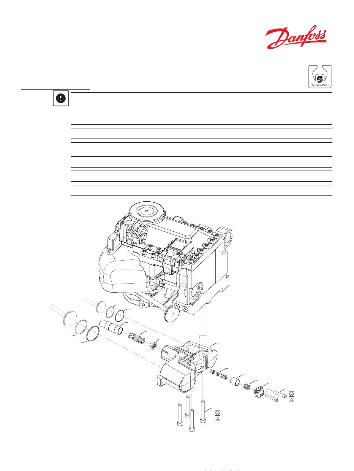
Older Sphinx controls are not compatible with current Apex control service parts. To determine if the RE592894
Hydrostatic Control Service Kit is needed or if control components can be serviced on an individual basis,
the diameter of the feedback cam guide(#3) needs to be measured . If largest diameter is ~35 mm, the full
RE592894 kit needs to be purchased if any 1 of the following 4 parts need to be replaced:
• Control Housing (#1)
• Feedback Cam Guide (#3)
• Guide Spring [retainer] (#4)
• Spring (#5)
If the feedback cam guide is ~Ø30 mm, parts may be serviced on an individual basis.
26
22
3
25
21
© Danfoss, 2016 AX279272222358en-000101 | 70367696• Rev 0101 • August 2018 1
5
4
1
9
11
10mm
135Nm [100 ft-lb]
7
8
6
2
6mm
34Nm [25 ft-lb
Page 2
Install Control Spool
Ball side
Shallow side
--------->
4
3
into housing
1. Assemble control spool (#9) into control housing (#1)
with the ball side facing into the spool bore. Check for
free movement.
Ball side
--------->
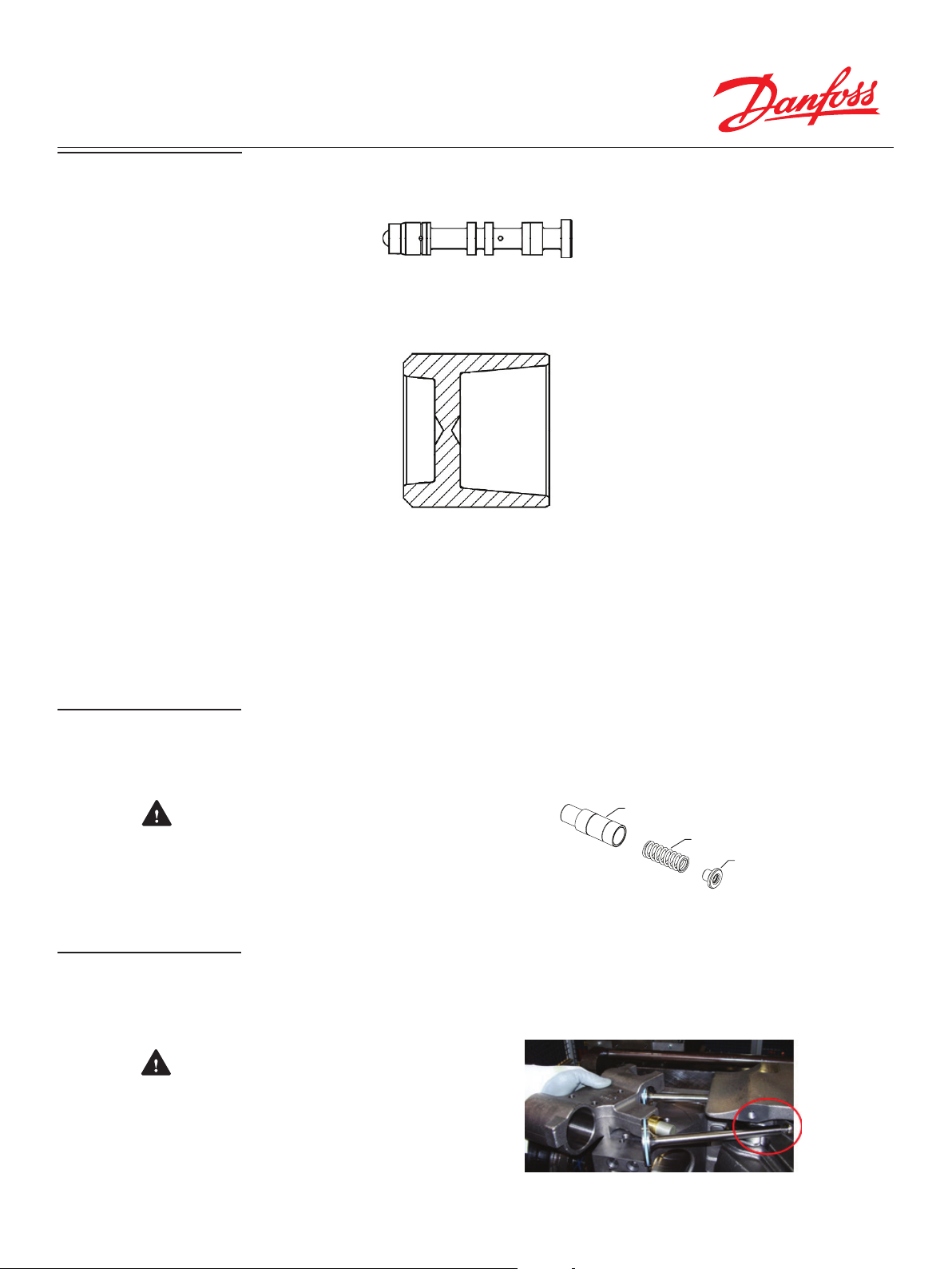
2. Install centering valve plunger (#7) with the shallow
side facing into the spool bore, see cutaway below.
--------->
3. Install cold start valve spring (#8) into the plunger
(#7).
4. Install cap (#6) and hand start the cap screws (#2)
5. Using a 6mm internal hex wrench, torque cap screws
(#2) to 34 Nm [25 ft-lb]
Install Feedback Cam
Install Piston Seal
Rings
6. Install spring guide (#4), control feedback spring (#5),
and feedback cam guide (#3) into the cam bore.
CAUTION - Spring guide (#4) must be
oriented so the control feedback spring (#5) is
seated on guide
7. Install O-rings (#25 & #26) onto pistons before
installing ring-seals (#21 & #22) onto pistons. Oil ringseals and inside of bore before installing into control.
CAUTION - When removing old and
installing new seals, do not stress ball and socket
joint. Piston neck should not contact casting.
5
© Danfoss, 2016 AX279272222358en-000101 | 70367696• Rev 0101 • August 2018 2
Page 3

Assemble control to
unit
8. Start pistons into control bores at an angle and align
control with mounting holes.
9. Hand start control mounting screws (#11) making
sure they move freely.
10. Visually look into the servo piston bores to inspect
the piston ring-seals for cut or protruding material, if
present replace the outer ring-seals (#21 & #22).
11. Check that the Feedback Cam Guide (#3) is on the
Cam surface.
12. Using a 10mm internal hex wrench, torque 4 screws
(#11) to 135 Nm [100 ft-lb] following the below torque
sequence.
1
3
4
© Danfoss, 2016 AX279272222358en-000101 | 70367696• Rev 0101 • August 2018 3
2
 Loading...