

Page 1
Technical Information
Hydraulic Fluids and Lubricants
Oils, Lubricants, Grease, Jelly
powersolutions.danfoss.com
Page 2

Technical Information
Hydraulic Fluids and Lubricants
Revision history Table of revisions
Date Changed Rev
July 2016 Major update. Updated for Engineering Tomorrow. 0801
November 2015 Minor text change. 0703
Mar 2014 Converted to Danfoss layout – DITA CMS HD
Oct 2002 New Edition AA
2 | © Danfoss | July 2016 520L0463 | BC00000093en-US0801
Page 3

Technical Information
Hydraulic Fluids and Lubricants
Contents
General Information
Disclaimer............................................................................................................................................................................................4
Introduction........................................................................................................................................................................................4
Health, accident and environmental measures.....................................................................................................................4
API Classes of the base oil..............................................................................................................................................................5
Hydraulic fluid features.................................................................................................................................................................. 5
Viscosity..........................................................................................................................................................................................6
Viscosity index (VI)...................................................................................................................................................................... 7
Sealing compatibility.................................................................................................................................................................9
Air in hydraulic fluid.................................................................................................................................................................10
Bulk modulus..............................................................................................................................................................................11
Compressibility..........................................................................................................................................................................12
Water contamination....................................................................................................................................................................13
Water solubility...............................................................................................................................................................................13
Requirements for Hydraulic Fluids
Fluid type-related standards and specifications.................................................................................................................14
Fluid cleanliness............................................................................................................................................................................. 15
Fluid change intervals.................................................................................................................................................................. 15
Traces of wear metals and contamination............................................................................................................................16
Viscosity and temperature limits..............................................................................................................................................17
Viscosity – Temperature diagrams.......................................................................................................................................... 18
Fire Resistant Hydraulic Fluids
HFA fluids – oil in water emulsions, according to ISO 12 922. ......................................................................................25
HFB fluids – water in oil emulsions, according to ISO 12 922. ...................................................................................... 25
HFC fluids – water polymers / water glycols, according to ISO 12 922. .................................................................... 25
HFD fluids – water free, synthetic fluids according to ISO 12 922. ..............................................................................25
General operating parameters for fire resistant hydraulic fluids..................................................................................26
Specific operating parameters for products running with fire resistant fluids....................................................... 27
Biodegradable Hydraulic Fluids
Biodegradable hydraulic fluids according to ISO 15 380................................................................................................ 28
HETG - Triglyceride hydraulic fluids...................................................................................................................................29
HEPG – Polyglycol hydraulic fluids.....................................................................................................................................30
HEES – Synthetic ester based hydraulic fluids............................................................................................................... 31
HEPR – Polyalphaolefins and related hydrocarbon hydraulic fluids......................................................................32
Viscosity – Temperature Diagram............................................................................................................................................33
Gear Lubricants
Features.............................................................................................................................................................................................34
Gear lubricants specifications....................................................................................................................................................34
Example for selecting the kinematic viscosity - transit mixer drive (agitate mode)..............................................35
Viscosity – Temperature diagrams.......................................................................................................................................... 36
Gear Bearing Grease
Features.............................................................................................................................................................................................38
Dropping point (ISO 2176)....................................................................................................................................................38
Miscibility of gear bearing grease.......................................................................................................................................38
Storage of gear bearing grease........................................................................................................................................... 38
Consistency.................................................................................................................................................................................38
Preservation fluids and petroleum jelly
Features of preservation fluids..................................................................................................................................................39
Features and application of petroleum jelly........................................................................................................................40
©
Danfoss | July 2016 520L0463 | BC00000093en-US0801 | 3
Page 4

C
Technical Information
Hydraulic Fluids and Lubricants
General Information
Disclaimer
Any warranty applicable for failures related to components of Danfoss Power Solutions does not apply
for any fluid related damages, unless such warranty has been expressly and specifically granted.
The rated data which is published in this Technical Information and Service Manuals is based on the use
of premium lubricants containing oxidation, rust and foam inhibitors.
Caution
It is not permissible to mix lubricants, different additive packages may cause negative interactions. If
lubricant mixing cannot be avoided, fluid manufacturer’s approval is required.
Introduction
The purpose of this manual is to aid the machine operator in the selection of suitable hydraulic fluid, gear
lubricants, gear bearing grease, preservation fluid and petroleum jelly.
The specifications of the lubricant manufacturer and the recommendations of the machine manufacturer
are the basis for selection and subject to change without advance advice. The choice of suitable hydraulic
fluids or lubricants is critical for the lifetime, operational safety and efficiency of hydrostatic components
and gears.
If there are any fire hazards, see instructions in Health, accident and environmental measures on page 4.
The selection of the appropriate hydraulic fluid or gear lubricant for a specific application can be made
only when the different features of the lubricants and the task and conditions under which the machine
is to operate are taken into consideration. Content subject to change.
Health, accident and environmental measures
When operating units, which are filled with hydraulic fluids, gear lubricants, grease or preservation fluids
(hereafter referred to as lubricants) the operator must consider, among other things, the following
precautionary measures:
Prolonged skin contact with the lubricants is to be avoided. Careful skin cleansing of sticky fluid and
•
regular changing of with lubricant soiled work clothes is required.
Skin contact with fluid or with heated unit parts is to be avoided, especially at temperatures over 60
•
°C [140 °F].
Should lubricant get into your eyes, rinse them thoroughly with tap water and see a doctor if
•
necessary.
Official regulations must be observed when storing lubricants (e. g. fire extinguishers, emergency
•
exits).
If there are any fire hazards, the use of fire resistant fluids is recommended.
•
Clean up spills to avoid slipping (e. g. normal commercial cleaning agents).
•
Lubricants must not seep into the ground or get into the sewer system.
•
Concrete floors as foundations can be protected against fluids by being sealed or being painted with
•
fluid-resistant paint.
The first time start up of systems filled with hydraulic fluid, all unnecessary personnel has to stay away
•
from the system.
Old or unusable fluids are to be collected. Quantities above 200 liters [53 US gal] are presently picked
•
up free of charge in Germany by the authorized collectors, as long as prohibited foreign substances
are not added to these.
For safety reasons, the flash point of the hydraulic fluid should always be at least 20 °C [68 °F] above
•
the maximum fluid working temperature.
Current official regulations must be observed.
•
4 | © Danfoss | July 2016 520L0463 | BC00000093en-US0801
Page 5
Technical Information
Hydraulic Fluids and Lubricants
General Information
API Classes of the base oil
Fully formulated hydraulic fluids consist of a blend of a base fluid and an additive package. These base
fluids are categorized by the American Petroleum Institute (API) into five groups – API 1509, Appendix E.
The differentiation between them bases on the refining method, amount of saturates, viscosity and
percentage of sulfur. Only groups I to III are products from the refinement of a petroleum crude.
Due to different manufacturing processes, these fluids show different content of saturates and different
viscosity indices (VI). Group I to III fluids can include some VI-improvers, which result in higher VI. Group
IV and V represent synthetic fluids. Thereby group IV includes polyalphaolefines (PAO) and group V all
residual fluids, which do not fit into the group I-IV as example biodegradable HEES, HETG and HEPR.
Base oils specification
Oil type Mineral base oils Synthetic base oils
Group I II III IV
Saturates
Viscosity Index
Sulfur
Manufacturing
Process
Polarity
1)
Group IV - polyalphaolefines
1)
< 90% > 90% > 90% 100% All other fluids,
80-120 80-120 > 120 > 135
> 0,03% < 0,03% < 0,03% —
Solvent refined Hydrothreated Hydrocracked Synthesized
high low unpolar low often high
V
including HEES,
HEPG, HEPR
Hydraulic fluid features
Hydraulic fluids have the primary purpose of transferring potential or kinetic energy (pressure and
movements), create volume flow between pump and hydrostatic motor, and reduce the wear of parts
that rub against each other. In addition, they protect the system from corrosion and help carry away the
heat produced during energy transformation.
The following tables give an outline of the requirements for hydraulic fluids:
Necessary characteristics of hydraulic fluid
Required Prerequisites
Volume stability adequate capacity to separate air
Wear protection capacity for a hydrodynamic or hydrostatic fluid layer between sliding surfaces
adequate viscosity at operating temperature
for all others wear reducing additives
Corrosion protection capacity non–aggressive toward customary materials and rust protection additives
Desirable characteristics of hydraulic fluid
Desirable Prerequisites
Only slight change in usage adequate oxidation resistance
for some cases of application adequate deemulsification capacity
adequate shear stability, if polymer viscosity index improvers are used
Viscosity–temperature behavior so that oil changes due to summer and winter operation become redundant
adequate Viscosity–Temperature behaviour
Interaction with seals / gaskets standard sealing materials can be used
minimal characteristics changes of standard elastomers
For most of the identifying characteristics listed in the table, there already exist standards or at least
preferred testing procedures which allow a numerical classification of these identifying features.
©
Danfoss | July 2016 520L0463 | BC00000093en-US0801 | 5
Page 6

Technical Information
Hydraulic Fluids and Lubricants
General Information
Hydraulic fluid has to perform the following tasks:
•
Energy transmission
•
Lubrication
•
Heat removal
When choosing a hydraulic fluid the following features are most important for consideration:
•
Viscosity
•
Viscosity Index (VI) and/or Viscosity Grade (VG) viscosity at 40 °C [104 °F].
•
Pour point
•
Shear stability, when polymer VI-improvers are used
For any application the features of the hydraulic fluid must be appropriate to the operating environment
of the unit and its components.
The fundamental features of the hydraulic fluids are described below.
Viscosity
A hydraulic fluid has a low viscosity when it is thin and a high viscosity when it is thick. The viscosity
changes with the temperature.
If the temperature increases, viscosity is reduced.
•
If the temperature decreases, viscosity is increased.
•
Hydraulic units work under extreme temperature changes, especially in heavy duty vehicles. The viscosity
range of the hydraulic fluid is extremely important.
The hydraulic fluid must be thin enough to flow through the filter, inlet and return pipes without too
much resistance.
On the other hand, the hydraulic fluid must not be too thin, in order to avoid wear due to lack of
lubrication and to keep internal leakage within limits.
In the hydraulic business typically the kinematic viscosity 'ν' in mm2/s [SUS] is used for calculations,
mainly for calculating the pressure drop in the connecting hoses and pipes.
The other measure is the dynamic viscosity 'η' in mPa•s. Dynamic viscosity is used for calculating the
lubricating film thickness in a journal bearing and similar sliding films between adjacent parts.
Conversion of viscosities:
Dynamic viscosity (η) = kinematic viscosity (ν) x density (ρ): η = ν • ρ (mPa•s)
6 | © Danfoss | July 2016 520L0463 | BC00000093en-US0801
Page 7
Viscosity-Temperature
from Prof. Dr. L. Ubbelohde
S.Hirzel Verlag, Stuttgart N
3,0
3,5
4,0
4,5
5
6
7
8
9
10
11
12
14
16
18
20
25
30
40
50
60
70
80
90
100
2,7
150
200
300
400
500
600
700
800
1000
1500
2000
3000
4000
5000
7000
10000
20000
30000
50000
70000
100000
200000
300000
500000
2000000
-50
-45
-40 -35 -30 -25 -20
-17,78 oC (0 oF)
-15 -10-50+510 15 20 25
30
40
37,78 oC [100 oF]
50
60
70 80 90 100
98,89 oC (210 oF)
110 120 130 140 150 160
3
3,5
4
5
6
7
8
9
10
12
14
16
18
20
25
30
40
50
60
70
80
90
100
4,5
mm /s
2
-40 -30 -20 -10 0 10 20
30
40
50
60
70 80 90 100 110 120 130 140 150
1000000
Kinematic viscosity [mm
2
/s]
Temperature oC [oF]
max. 95 oC
All e Recht e vorbehalten . Copyrigh t 195 7 b y S . Hirze l Verlag , Stuttgart .
Printe d in Germany . Jed e Ar t des Nachdrucke s bzw . de r Vervielfälti gung einschl. Fotokopieren ist unzulässig und wird rechtlich verfolgt.
P002 062E
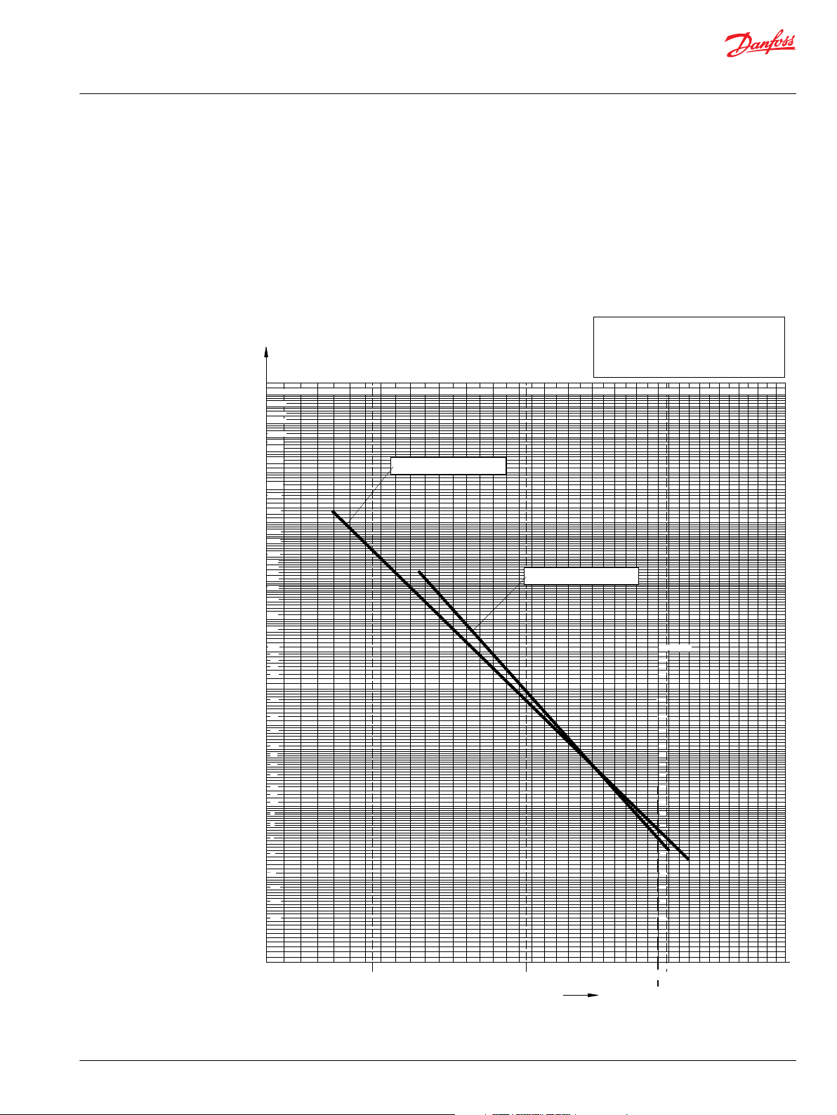
Hydraulic Fluid 2 VI 153
Hydraulic Fluid 1 VI 100
Technical Information
Hydraulic Fluids and Lubricants
General Information
Viscosity index (VI)
The viscosity index is a calculated number according to DIN ISO 2909, which describes the viscosity
change of a mineral oil based or a synthetic fluid in dependence of temperature.
a high viscosity index means a small viscosity change when the temperature changes
•
a low index means a large viscosity change when the temperature changes
•
Viscosity – temperature diagram according to Ubbelohde representing the temperature operating range
of hydraulic fluids with different viscosity index (VI).
Viscosity – Temperature diagram from Prof. Dr. Ubbelohde
©
Danfoss | July 2016 520L0463 | BC00000093en-US0801 | 7
Standard mineral oil based (Group I and Group II) hydraulic fluids have a VI value of 90 – 110.
Page 8

Technical Information
Hydraulic Fluids and Lubricants
General Information
Hydraulic fluids with a VI larger than 110, e.g. between 130 – 200, are not as sensitive to temperature
change. These hydraulic fluids distinguish themselves by starting up well and having minimal loss in
performance at low temperatures. At high temperatures a sufficient sealing effect and protection against
wear is achieved by using hydraulic fluids with high viscosity index. The high durability of a hydraulic
fluid with a high viscosity index avoids damage and machine breakdown, lowers the operating cost and
increases the life of hydrostatic transmissions and units.
Shear stability
Fluids using polymer viscosity index improver may noticeably shear down (> 20 %) in service. This will
lower the viscosity at higher temperatures below the originally specified value. The lowest expected
viscosity must be used when selecting fluids. Consult your fluid supplier for details on viscosity shear
down.
Pour point
The pour point according to ISO 3016 defines the temperature when the fluids stops to flow. Start up
temperature is recommended to be approximately 15 °C [59 °F] above hydraulic fluid pour point.
Density
The density has to be specified by the manufacturer of the hydraulic fluid. Using hydraulic fluid with a
high density requires the sufficient diameter of the suction line and/or elevated tank to provide positive
inlet pressure.
Examples for density at 15 °C [59 °F]
Hydraulic fluid type Density at 15 °C [59 °F]
Petroleum (mineral) based fluids
Syntetic ester
Rape seed oil
Water
Polyalkylenglykol
HFC
Polyethylenglykol
HFD (phosphate ester)
0.86 — 0.90 g/ml
0.92 — 0.926 g/ml
0.92 g/ml
1.00 g/ml
1.02 g/ml
1.08 g/ml
1.10 g/ml
1.13 g/ml
8 | © Danfoss | July 2016 520L0463 | BC00000093en-US0801
Page 9

Technical Information
Hydraulic Fluids and Lubricants
General Information
Sealing compatibility
The procedure for testing the compatibility of the seal material is described in ISO 6072. In general NBR
(Nitrile) or FPM (Fluorocarbon, Viton) is used as seal material for static and dynamic seals. For most
hydraulic fluids both seal materials are suitable, but for some hydraulic fluids only one kind is preferred.
Suitable seal material allocated to the hydraulic fluid is shown in the table below. When ordering
hydrostatic products the desired hydraulic fluid should be specified.
Sealing compatibility
Hydraulic fluid Suitable test material according to ISO 6072
Mineral based hydraulic fluids
Water-in-oil emulsions HFB
Polyol esters HFDU
Biodegradable synthetic esters HEES
Triglycerides (vegetable-oil-based) HETG
Poly(α-olefin) compounds and related hydrocarbons HEPR
Water/glycol mixtures HFC
Alkyl phosphate esters HFDR
Poly(alkylene glycol) compounds HEPG
*
Depending on the base fluid other seal material may be recommended. Please contact fluid and/or seal
manufacturer for other suitable materials.
Standards: NBR 1, NBR 2 and FPM 2
*
Standards: NBR 1, NBR 2
Standard FPM 2Aryl phosphate esters HFDR
©
Danfoss | July 2016 520L0463 | BC00000093en-US0801 | 9
Page 10
Technical Information
Hydraulic Fluids and Lubricants
General Information
Air in hydraulic fluid
Air in a system is regarded as a contaminant. Air increases the compressibility of the fluid, resulting in a
“spongy” system that is less responsive. Air creates a loss of transmitted power, higher operating
temperatures, increased noise levels, and loss of lubricity.
Air typically enters the circuit through the suction line if the seals and fittings are not tight. This free air
then may be dissolved in the hydraulic fluid. Mineral based hydraulic fluid may contain up to 9 % volume
percent dissolved air at atmospheric pressure.
If 1 l [0.264 US gal] of hydraulic fluid is compressed to 100 bar [1450 psi], it may dissolve 9 l [2.377 US gal]
of free air if offered.
This is not a problem unless the pressure drops down quickly to a lower level. Then the air becomes free
again and bubbles show up. These bubbles collapse when subjected to pressure, which results in
cavitation which causes erosion of the adjacent material. Because of this, the greater the air content
within the oil, and the greater the vacuum in the inlet line, the more severe will be the resultant erosion.
The bubbles may also result in a spongy system, slow response time, and poor controllability. Therefore
care must be taken to avoid air to enter the system. If air has entered a system the air release time and
foam characteristic becomes important.
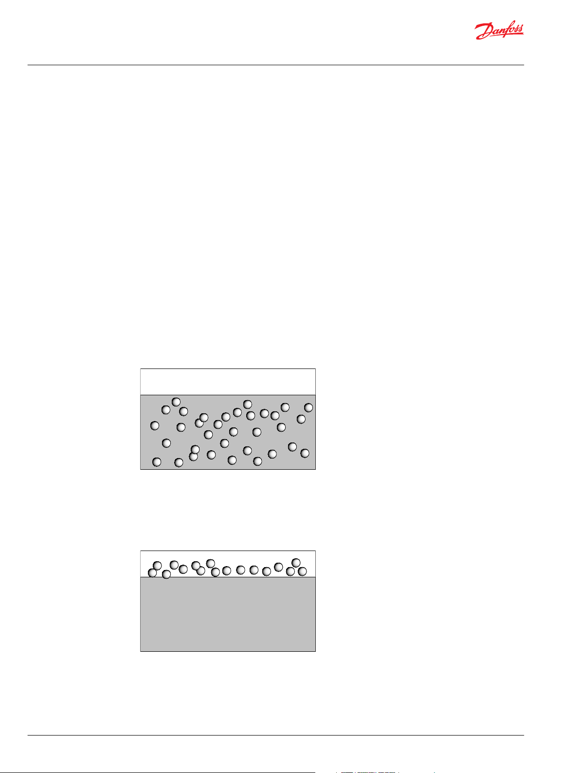
Air release
Air release is a measure for the time needed to release air bubbles (free air) contained in the fluid to the
surfaces. Air typically enters the circuit through the suction line if the seals are not tight as explained
above. Air release time is tested according to ISO 9120.
Foaming characteristic
Foaming characteristic defines the amount of foam collected on the surface in the reservoir and the air
bubble decomposition time. Foaming may become a problem when air has entered the circuit as
explained above, through an insufficient tight suction line. The foaming characteristic of a hydraulic fluid
is tested according to ISO 6247.
10 | © Danfoss | July 2016 520L0463 | BC00000093en-US0801
Page 11
Stiffer
Bulk modulus bar [psi]
increasing
oscillation
tendency,
Spongy
D pressure bar [psi]
20
o
C [68
o
F]
40
o
C [104
o
F]
80
o
C [176
o
F]
Technical Information
Hydraulic Fluids and Lubricants
General Information
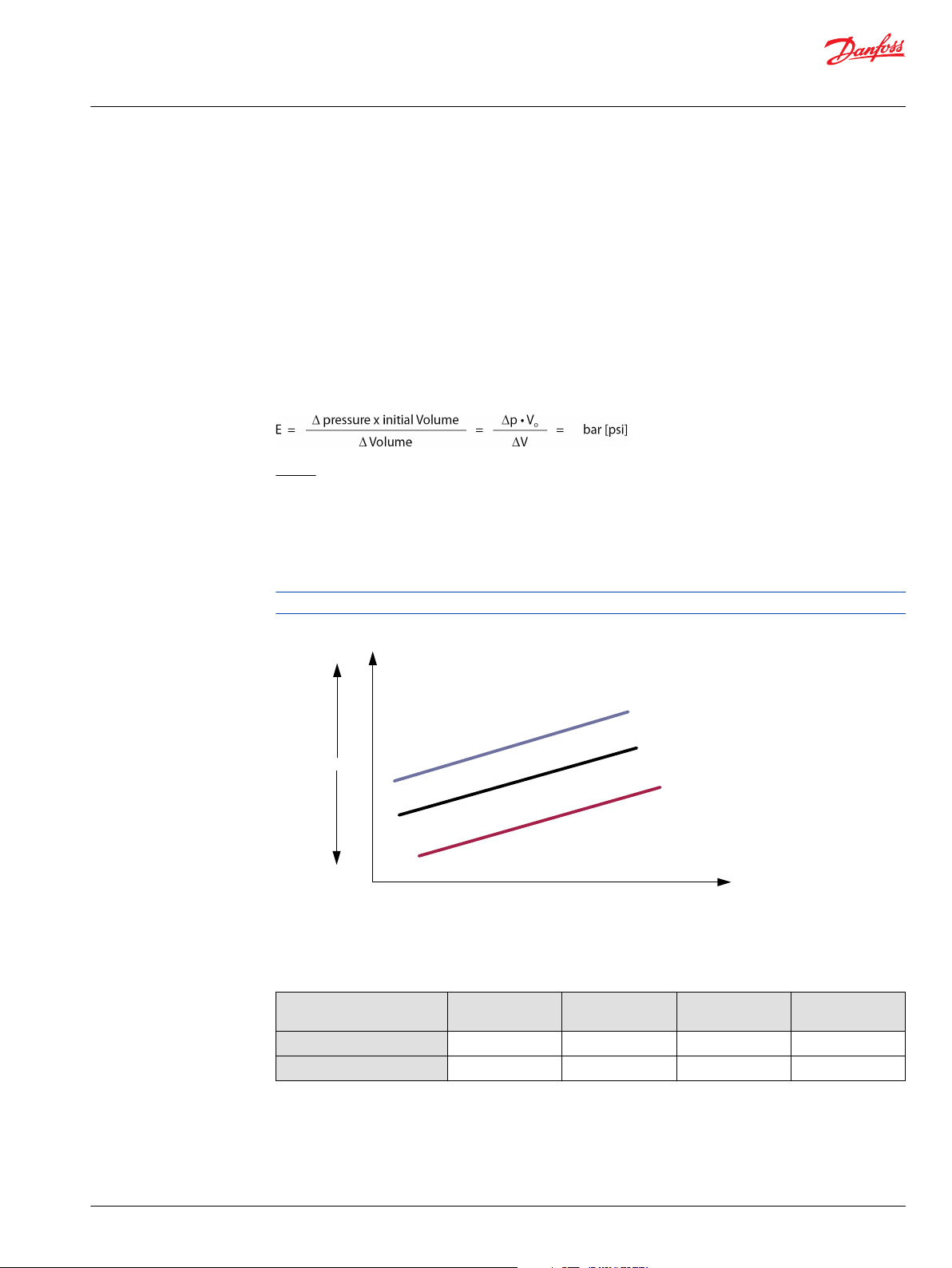
Bulk modulus
While fluids are usually considered incompressible, the pressures that can occur in hydrostatic systems
are of a magnitude that fluid compressibility can be significant. In applications that experience system
pressure fluctuations resulting in random high pressure rise rates, consideration must be given to fluid
compressibility when sizing a charge pump to ensure adequate charge pressure.
The amount that a specific fluid compresses for a given pressure increase is related to a fluid property
known as the bulk modulus. The bulk modulus is a measure of a fluids resistance to being compressed. It
depends on pressure and temperature. The air content is important as well especially below 50-100 bar
[725-1450 psi]. The higher the air content the more spongy the system (lower bulk modulus). For a given
pressure increase and fluid volume, a fluid with a large bulk modulus will experience a smaller reduction
in volume than a fluid with a low bulk modulus.
Mathematically, bulk modulus is defined as follows:
Where:
E = bulk modulus of the fluid bar [psi]
∆p = change in pressure bar [psi]
∆V = change in volume l [US gal]
Vo = volume of oil experiencing the change in pressure l [US gal]
Units for bulk modulus are the same as the units for pressure.
Bulk modulus vs. ∆ pressure for different temperatures
Bulk modulus increases with increasing pressure (stiffer) and decreases with increasing temperature
(spongy).
Examples for bulk modulus at 22 °C [71.6 °F]
@Pressure Water HFC HFD Mineral
140 bar [2031 psi]
300 bar [4351 psi]
©
Danfoss | July 2016 520L0463 | BC00000093en-US0801 | 11
11 000 15 500 16 000 15 000
15 000 19 000 19 500 16 000
(petroleum) HF
Page 12
100 bar
[1450 psi]
200 bar
[2901 psi]
DV
Technical Information
Hydraulic Fluids and Lubricants
General Information
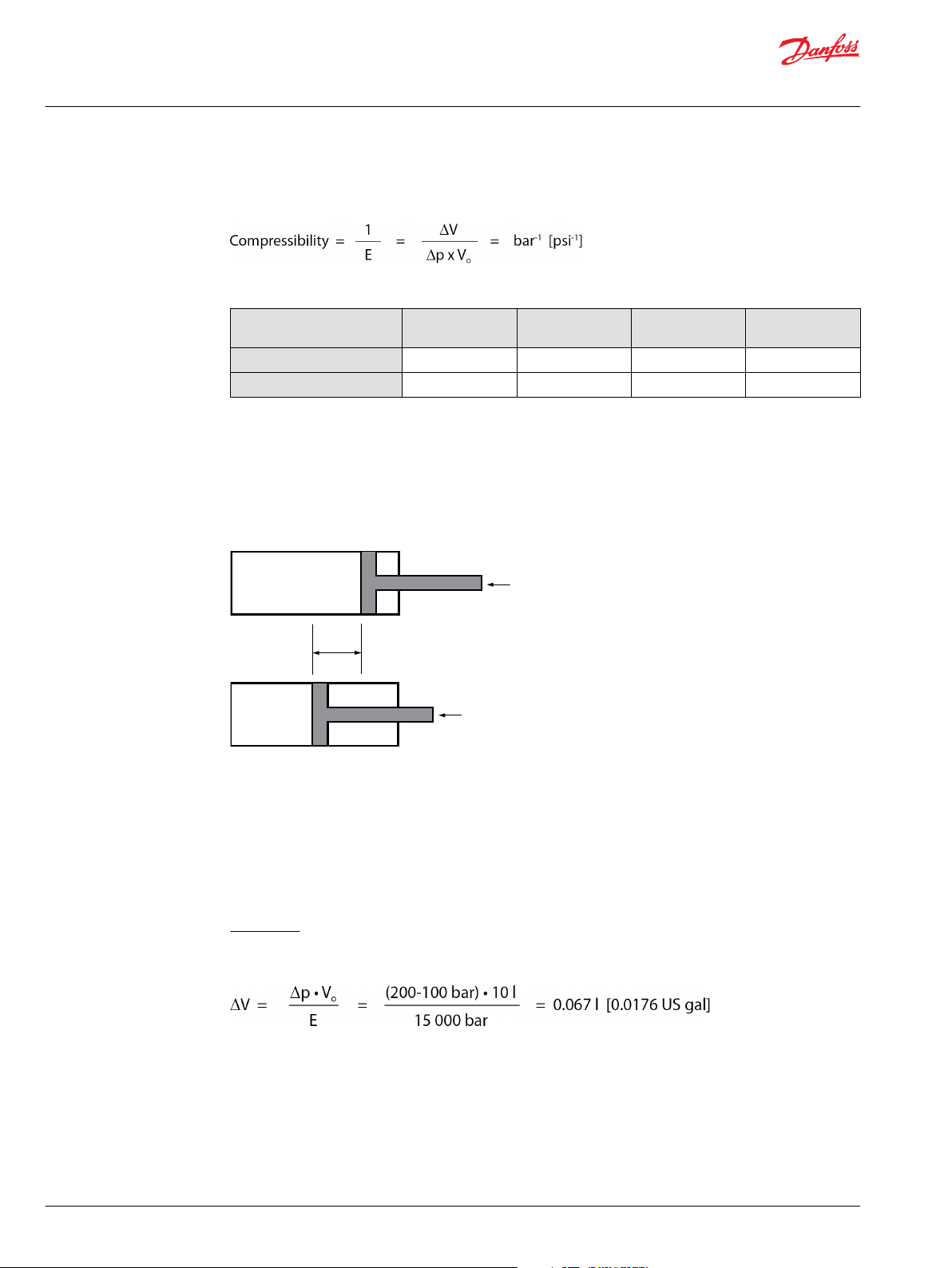
Compressibility
Compressibility is the reciprocal of the bulk modulus. It defines how much a fluid can be compressed.
Examples for compressibility at 22 °C [71.6 °F]
@Pressure Water HFC HFD Mineral
140 bar [2031 psi]
300 bar [4351 psi]
Fluid compressibility becomes a concern for a hydrostatic system which has large volumes of oil under
pressure, such as long or large system lines, and experiences high system pressure spikes during
operation.
To understand the nature of the problem that can be associated with fluid compressibility, consider what
happens when a system experiences an increase in load. An increase in load requires more torque from
the motor, and consequently, an increase in system pressure. When the system pressure increases, the
fluid in the high pressure side of the hydrostatic loop is compressed.
91 x 10
67 x 10
(petroleum) HF
-6
-6
65 x 10
53 x 10
-6
-6
63 x 10
51 x 10
-6
-6
67 x 10
63 x 10
-6
-6
The illustration shows a simple model consisting of a cylinder whose piston compresses the fluid to
create a pressure of 100 bar [1450 psi]. If a load forces the piston to move a small distance to the left, the
fluid compresses even more, resulting in the pressure increasing to 200 bar [2900 psi].
The fluid at this pressure now occupies a smaller volume than the fluid did at 100 bar [1450 psi]. At the
same time, the volume on the rod side of the piston increases. If we imagine that the rod side of the
piston is also filled with fluid, then a void is created on this side of the piston when the fluid against the
piston face is compressed. To keep the rod side of the piston full of fluid, additional fluid must be added
to this side of the piston.
Calculation:
The hydraulic fluid volume under pressure in the cylinder is 10 l [2.64 US gal]. As approach the bulk
modulus for 140 bar [2031 psi] as shown above is used.
12 | © Danfoss | July 2016 520L0463 | BC00000093en-US0801
Page 13
C
Technical Information
Hydraulic Fluids and Lubricants
General Information
Water contamination
Non-dissolved water in a fluid is to be considered as contamination. It is one of the frequent reasons for
the failure of a hydraulic system. Increased content of water in a lubricant can lead to corrosion of parts,
water vapor cavitation, foam formation, filter clogging, oxidation of the fluid, depleting of additives and
consequentially enhanced wear or a failure of the system.
Furthermore the polymer seal material could be attacked by the fluid leading to leakages.
The water contamination of the fluid can have different reasons as for example condensing of water,
leakage of rain water into the system, leakage of cooling water and others.
Water solubility
Base oils of different types have limited water solubility. Blending the base oils with additives leads to a
significant increase of the water solubility. Also the amount and the kind of used additive packages are
crucial for this property. There is a general thumb rule: the higher the amount of additives, the higher the
water solubility of a fluid. Consequently different fluid types have different water absorptive capacity,
which depends on the molecular structure and the additive packages of the fluid. Some fluid types are
able to dissolve more water by integrating it in the molecular structure, others less. When the absorbance
of water reaches the saturation point, residual water separates from the fluid forming free water.
Dissolved water in fluid is less harmfull than free water, since it is bound and has no reactivity. In case of
pressure or temperature fluctuations dissolved water can get undissolved leading to an enormous
change of fluid properties. The consequences of that are listed above. Strongly increased content of free
water in a fluid can be detected optically, since it is leading to a clouding of the fluid.
The water in a fluid can be measured by different methods. Traditionally, Karl-Fischer-titration is used,
which is used to determine the total water content. ISO 760 describes this procedure in general.
Measuring the total water content means, there is no possibility to distinguish between the dissolved and
undissolved water by using this method, making ppm values describing the water content often not
sufficient enough.
Examples for critical water content of different fluids:
Fluid type Critical water content
Mineral oil (HLP) 200 ppm — 500 ppm
Mineral oil with D-additives (HVLPD) 600 ppm — 1200 ppm
Biodegradable oil (HEES) 700 ppm
Fire resistant fluid (HFC=Water in Glycol emulsion) > 4000 ppm
Universal Tractor Transition Oil (UTTO) 1000 ppm — 2000 ppm
Caution
All numbers in this table are only rough guides, which strongly differ in dependency with the used base
oil, additive packages and the application of the hydraulic system.
©
Danfoss | July 2016 520L0463 | BC00000093en-US0801 | 13
Page 14

Technical Information
Hydraulic Fluids and Lubricants
Requirements for Hydraulic Fluids
Fluid type-related standards and specifications
Mineral oil based hydraulic fluids according to specification:
•
DIN 51524-2: Mineral oil hydraulic fluids of category HLP
•
DIN 51524-3: Mineral oil hydraulic fluids of category HVLP
•
ISO 11158: Mineral oil hydraulic fluids of category HM
•
ISO 11158: Mineral oil hydraulic fluids of category HV
Environmentally acceptable fluids according to specification ISO 15380 of category:
•
HEES (synthetic esters) meeting Annex B of ISO 15380 (shear stability test & yellow metal test)
•
HETG (tri-glycerides) meeting the same pour point specification as Category HEES and meeting
Annex B of ISO 15380 (shear stability test & yellow metal test)
•
HEPG (poly-glycols) meeting Annex B of ISO 15380 (shear stability test & yellow metal test)
•
HEPR (poly-alpha-olefins, PAO)
Automatic Transmission Fluids (ATF) according to OEM specification
In additional to the international standards there is a variety of OEM specifications for fluids.
To meet the basic requirements for fluids all of the below mentioned ATF fluids must additionally meet
the requirements of Table 3 in ISO 11158.
•
GM ATF A Suffix A VI
•
GM Dexron, which meets Allison C-4 and Caterpillar TO-4 test, downwards compatible with GM
Dextron II or III
•
Ford M2C33F and G
•
Mercon V, Mercon LV
•
ATF DW-1
•
SP-IV or SP4
•
Matic S, Matic L, Matic D
•
ATF T-IV
•
Toyota ATF-WS
•
Honda DW
Gear Oils
In additional to the international standards there is a variety of gear oil specifications for fluids, which are
described in ISO 12925-1. To meet the basic requirements for fluids both of the below mentioned gear
fluids must additionally meet the requirements of Table 3 in ISO 11158.
•
API GL-4
•
API GL-5
Engine Oils
In additional to the international standards there is a variety of engine oil specifications for fluids, which
are described in ISO 6743-15.
To meet the basic requirements for fluids all of the below mentioned engine oils must additionally meet
the requirements of Table 3 in ISO 11158.
•
Engine oils API Classification CI-4, CH-4, CG-4, CF-4 and CF (for diesel engines), where the latest
category usually – but not always – includes the performance properties of an earlier category.
•
Super Tractor Oil Universal (STOU), which meets the requirements up to API CF-4
•
API GL4 with Limited- Slip (LS) additives
14 | © Danfoss | July 2016 520L0463 | BC00000093en-US0801
Page 15

Technical Information
Hydraulic Fluids and Lubricants
Requirements for Hydraulic Fluids
The following fluid classes meet the necessary requirements for the usage in hydrostatic units, but
significant changes of the lifetime can be present:
•
Premium Turbine Oils
•
Tractor Oil Universal (TOU)
•
Fire resistant fluids HFA, HFB, HFC, and HFD are suitable at modified operating parameters, but not
with gear pumps and motors.
Contact the fluid manufacturer for more information about the suitability of a fluid in the expected
application.
Fluid cleanliness
The cleanliness of a fluid is one of the most important features to guarantee a satisfying performance of
the hydraulic system. Contamination of a fluid with solid particles can lead to a failure of the complete
hydraulic system by locking of the pistons or blocking the valves. Different systems have different
sensitivity to solid contamination of the fluid, so different levels of fluid cleanliness are determined by ISO
4406. The determination of the cleanliness level is made by counting the particles, distinguishing the
particle size.
Further information to fluid cleanliness, filter compatibility in a system and the cleanliness levels can be
found in the document Design Guidelines for Hydraulic Fluid Cleanliness, Technical Information,
BC00000095.
Fluid change intervals
Danfoss recommends the following fluid change intervals for all fluids except those mentioned below:
First change: 500 operating hours after start up
•
Second and subsequent change every: 2000 operating hours or once a year
•
For HFA, HFB, HFC, HFD and biodegradable hydraulic fluids HETG shorter fluid change intervals are
recommended:
First change: 500 operating hours after start up
•
Second and subsequent change every: 1000 operating hours or once a year
•
This recommendation applies for most applications. High temperatures and pressures will result in
accelerated fluid aging and an earlier fluid change may be required. At lower fluid pressure loads longer
change intervals are possible. Therefore we suggest taking a sample of the fluid at least one time,
preferably more, between scheduled fluid changes. This fluid sample then can be sent to the fluid
manufacturer or an appropriate laboratory for an analysis and a determination of its suitability for
continued use.
©
Danfoss | July 2016 520L0463 | BC00000093en-US0801 | 15
Page 16

Technical Information
Hydraulic Fluids and Lubricants
Requirements for Hydraulic Fluids
Traces of wear metals and contamination
Wear metals are the result of corrosive wear due to water and acids but also abrasive wear due to surface
roughness metal contact leading to welding. The table below shows typical amount of wear metals. In
some mobile applications for copper numbers up to 300 mg/kg and aluminum up to 80 mg/kg have
been found.
These metal traces are determined by Atom–Emission–Spectroscopy (AES) according to ASTM D5185-97.
Typically particles smaller than 5 µm are detected. Larger particles are discussed below in the fluid
cleanliness requirements section.
These metal traces may increase during operation. It is therefore important to monitor the wear metal
concentration during operation. A sudden increase is an indication for a soon wear failure or that parts
have been already damaged.
Typical values for traces of wear metal in hydraulic systems (mg/kg)
Fe Cr Sn Al Ni Cu Pb Mo
30 10 10 10 2 50 15 5
Silicium (Si) has the highest percentage in dust and is contamination in a system. Silicium is very abrasive
and a fluid change is recommended if 10–15 mg/kg are exceeded.
16 | © Danfoss | July 2016 520L0463 | BC00000093en-US0801
Page 17

Technical Information
Hydraulic Fluids and Lubricants
Requirements for Hydraulic Fluids
Viscosity and temperature limits
When using hydraulic fluid the viscosity and temperature limits in the table below are to be observed.
Under normal operating condition it is recommended to keep the temperature in the range of 30°C to
60°C.
Fluid temperature affects the viscosity of the fluid and resulting lubricity and film thickness. High
temperatures can also limit seal life, as most nonmetallic materials are adversely affected by use at
elevated temperatures.
Fluids may break down or oxidize at high temperatures, reducing their lubricity and resulting in reduced
life of the unit. As a rule of thumb, fluid temperature increase from 80 °C [176 °F] to 90 °C [194 °F] may
reduce fluid life by 50%.
Overview on viscosity and temperature limits
Product line Min. vicosity
H1B 5 [ 42.38] 115 [239] 12-80
H1P
Series 15
Open circuit
Series 20 7 [48.79] 95 [203] 1000 [4629] -40 [-40]
Series 40 105 [221] 1600 [7406]
Series 42 115 [239]
Series 45 9 [55.51] 105 [221] 1000 [4629]
Series 51 7 [48.79] 115 [239] 1600 [7406]
Series 90 7 [48.79] 115 [239] -40 [-40]
TMP/TMM
LV/LC/KV/KC 105 [221]
Hydrostatic
steerings
Proportional
valves
Electrohydraulic
valves
Spool valves 6 [45.59]
Orbital motors 12 [66.03]
*
For OMR, OMH, OMS, OMT, OMV, TMT
**
For OML, OMM, OMP
Max.
(intermit.)
mm2/s [SUS]
12 [66.03] 85 [185] 860 [3981] -20 [-4]
10 [58.91] 90 [194] 1000 [4629] -30 [-22]
4 [39.17] 460 [2129]
12 [66.03] 82 [180] 440 [2037]
*
20 [97.69]
**
temperature
(intermit.)
o
C [oF]
90 [194] 20-80
Recommended
viscosity
mm2/s [SUS]
[66.03-370.3]
[97.69-370.3]
Max. cold start
viscosity
mm2/s [SUS]
1600 [7406] -40 [-40]
1500 [6944]
Min.
temperature
o
C [oF]
Fire resistant fluids HFA, HFB, HFC, and biodegradable fluids HETG have limited temperature capabilities.
Please see the individual fluids information given in this manual and contact the fluid manufacturer.
Viscosity – Temperature diagrams on page 18 shown on the next seven pages are for a reference only.
Please check actual viscosity with fluid manufacturer.
For more information to specific product lines please check the technical information to corresponding
product on the official http://www.powersolutions.danfoss.com website.
©
Danfoss | July 2016 520L0463 | BC00000093en-US0801 | 17
Page 18

3,0
3,5
4,0
4,5
5
6
7
8
9
10
11
12
14
16
18
20
25
30
40
50
60
70
80
90
100
2,7
150
200
300
400
500
600
700
800
1000
1500
2000
3000
4000
5000
7000
10000
20000
30000
50000
70000
100000
200000
300000
500000
2000000
-50
-45
-40 -35 -30 -25 -20 -15 -10
-5
0+510 15 20 25
30
40
50
60
70 80 90 100 110 120 130 140 150 160
3
3,5
4
5
6
7
8
9
10
12
14
16
18
20
25
30
40
50
60
70
80
90
100
4,5
mm /s
2
-40 -30 -20 -10 0 10 20
30
40
50
60
70 80 90 100 110 120 130 140 150
1000000
Kinematic viscosity mm
2
/s
Recommended
viscosity range
12-80 mm2/s
for all components
except for
OML, OMH + OMP
Orbital motors
n
max
intermittentcold start
Temperature oC
* hydrostatic motor only
P002 051E
ISO VG 100 (VI = 98)
ISO VG 68 (VI = 100)
ISO VG 46 (VI = 103)
ISO VG 32 (VI = 107)
ISO VG 22 (VI = 105)
Series 10,20
Series 45
Series 60,LPM*
Series 15
Gear Pumps + Motors
Hydrostatic steering
Series 40, 42, 51, 90, CW5-8*
Orbital motors OMR, OMH, OMS, OMT, OMV, TMT
Orbital motors OML, OMM, OMP
Cartridge + Electrohydraulic valve
Proportional valve
Spool valve
n
min
Technical Information
Hydraulic Fluids and Lubricants
Requirements for Hydraulic Fluids
Viscosity – Temperature diagrams
Hydraulic fluid according to DIN 51 524-2 HLP
18 | © Danfoss | July 2016 520L0463 | BC00000093en-US0801
Page 19

Kinematic viscosity mm
2
/s
Temperature oC
* hydrostatic motor only
3,0
3,5
4,0
4,5
5
6
7
8
9
10
11
12
14
16
18
20
25
30
40
50
60
70
80
90
100
2,7
150
200
300
400
500
600
700
800
1000
1500
2000
3000
4000
5000
7000
10000
20000
30000
50000
70000
100000
200000
300000
500000
2000000
-50
-45
-40 -35 -30 -25 -20 -15 -10
-5
0
+5
10 15 20 25
30
40
50
60
70 80 90 100 110 120 130 140 150 160
3
3,5
4
5
6
7
8
9
10
12
14
16
18
20
25
30
40
50
60
70
80
90
100
4,5
mm /s
2
-40 -30 -20 -10 0 10 20
30
40
50
60
70 80 90 100 110 120 130 140 150
1000000
Gear Pumps + Motors
Series 10,20
Series 60, LPM *
Series 45
Series 40, 42, 51, 90, CW5-8 *
Series 15
ISO VG 100 (VI = 170)
ISO VG 68 (VI = 180)
ISO VG 46 (VI = 180)
ISO VG 32 (VI = 165)
P002 052E
Recommended
viscosity range
12-80 mm2/s
for all components
except for
OML, OMH + OMP
Orbital motors
n
max
intermittentcold start
Orbital motors OMR, OMH, OMS, OMT, OMV, TMT
Orbital motors OML, OMM, OMP
Cartridge + Electrohydraulic valve
Proportional valve
Spool valve
n
min
Technical Information
Hydraulic Fluids and Lubricants
Requirements for Hydraulic Fluids
Hydraulic fluid according to DIN 51 524-3 HVLP
©
Danfoss | July 2016 520L0463 | BC00000093en-US0801 | 19
Page 20

3,0
3,5
4,0
4,5
5
6
7
8
9
10
11
12
14
16
18
20
25
30
40
50
60
70
80
90
100
2,7
150
200
300
400
500
600
700
800
1000
1500
2000
3000
4000
5000
7000
10000
20000
30000
50000
70000
100000
200000
300000
500000
2000000
-50
-45
-40 -35 -30 -25 -20 -15 -10
-5
0+510 15 20 25
30
40
50
60
70 80 90 100 110 120 130 140 150 160
3
3,5
4
5
6
7
8
9
10
12
14
16
18
20
25
30
40
50
60
70
80
90
100
4,5
mm /s
2
-40 -30 -20 -10 0 10 20
30
40
50
60
70 80 90 100 110 120 130 140 150
1000000
Kinematic viscosity mm
2
/s
Recommended
viscosity range
12 - 80 mm2/s
for all components
except for
OML, OMH + OMP
Orbital motors
n
max
intermittentcold start
Temperature oC
* hydrostatic motor only
P002 053E
Series 10,20
Series 45
Series 60,LPM*
Series 15
Gear Pumps + Motors
Hydrostatic steering
Series 40, 42, 51, 90, CW5-8*
n
min
Orbital motors OMR, OMH, OMS, OMT, OMV, TMT
Orbital motors OML, OMM, OMP
Cartridge + Electrohydraulic valve
Spool valve
Proportional valve
TYP A, SUFFIX A (VI = 154)
Technical Information
Hydraulic Fluids and Lubricants
Requirements for Hydraulic Fluids
Automatic Transmission Fluids (ATF) typ A, SUFFIX A (GM)
20 | © Danfoss | July 2016 520L0463 | BC00000093en-US0801
Page 21

3,0
3,5
4,0
4,5
5
6
7
8
9
10
11
12
14
16
18
20
25
30
40
50
60
70
80
90
100
2,7
150
200
300
400
500
600
700
800
1000
1500
2000
3000
4000
5000
7000
10000
20000
30000
50000
70000
100000
200000
300000
500000
2000000
-50
-45
-40 -35 -30 -25 -20 -15 -10
-5
0+510 15 20 25
30
40
50
60
70 80 90 100 110 120 130 140 150 160
3
3,5
4
5
6
7
8
9
10
12
14
16
18
20
25
30
40
50
60
70
80
90
100
4,5
mm /s
2
-40 -30 -20 -10 0 10 20
30
40
50
60
70 80 90 100 110 120 130 140 150
1000000
Kinematic viscosity mm
2
/s
Recommended
viscosity range
12-80 mm
2
/s
for all components
except for
OML, OMH + OMP
Orbital motors
n
max
int
ermittent-
cold start
Temperature oC
* hydrostatic motor only
P002 054E
Series 10,20
Series 45
Series 60,LPM*
Series 15
Gear Pumps + Motors
Hydrostatic steering
Series 40, 42, 51, 90, CW5-8*
Orbital motors OMR, OMH, OMS, OMT, OMV, TMT
Orbital motors OML, OMM, OMP
Cartridge + Electrohydraulic valve
n
min
Proportional valve
Spool valve
DEXRON II (VI = 166)
Technical Information
H
ydraulic Fluids and Lubricants
Requirements for Hydraulic Fluids
Automatic Transmission Fluids (ATF) DEXRON II
©
Danfoss | July 2016
520L0463 | BC00000093en-US0801 | 21
Page 22

3,0
3,5
4,0
4,5
5
6
7
8
9
10
11
12
14
16
18
20
25
30
40
50
60
70
80
90
100
2,7
150
200
300
400
500
600
700
800
1000
1500
2000
3000
4000
5000
7000
10000
20000
30000
50000
70000
100000
200000
300000
500000
2000000
-50
-45
-40 -35 -30 -25 -20 -15 -10
-5
0+510 15 20 25
30
40
50
60
70 80 90 100 110 120 130 140 150 160
3
3,5
4
5
6
7
8
9
10
12
14
16
18
20
25
30
40
50
60
70
80
90
100
4,5
mm /s
2
-40 -30 -20 -10 0 10 20
30
40
50
60
70 80 90 100 110 120 130 140 150
1000000
Kinematic viscosity mm
2
/s
Recommended
viscosity range
12-80 mm2/s
for all components
except for
OML, OMH + OMP
Orbital motors
n
max
intermittentcold start
Temperature oC
* hydrostatic motor only
P002 056E
Series 10,20
Series 45
Series 60,LPM*
Series 15
Gear Pumps + Motors
Hydrostatic steering
Series 40, 42, 51, 90, CW5-8*
Orbital motors OMR, OMH, OMS, OMT, OMV, TMT
Orbital motors OML, OMM, OMP
Cartridge + Electrohydraulic valve
n
min
Proportional valve
Spool valve
M2C33F/G (VI = 185)
Technical Information
Hydraulic Fluids and Lubricants
Requirements for Hydraulic Fluids
Automatic Transmission Fluids (ATF) M2C33F/G, FORD
22 | © Danfoss | July 2016 520L0463 | BC00000093en-US0801
Page 23

3,0
3,5
4,0
4,5
5
6
7
8
9
10
11
12
14
16
18
20
25
30
40
50
60
70
80
90
100
2,7
150
200
300
400
500
600
700
800
1000
1500
2000
3000
4000
5000
7000
10000
20000
30000
50000
70000
100000
200000
300000
500000
2000000
-50
-45
-40 -35 -30 -25 -20 -15 -10
-5
0+510 15 20 25
30
40
50
60
70 80 90 100 110 120 130 140 150 160
3
3,5
4
5
6
7
8
9
10
12
14
16
18
20
25
30
40
50
60
70
80
90
100
4,5
mm /s
2
-40 -30 -20 -10 0 10 20
30
40
50
60
70 80 90 100 110 120 130 140 150
1000000
Kinematic viscosity mm
2
/s
Recommended
viscosity range
12-80 mm2/s
for all components
except for
OML, OMH + OMP
Orbital motors
n
max
intermittentcold start
Temperature oC
* hydrostatic motor only
P002 057E
Series 10,20
Series 45
Series 60,LPM*
Series 15
Gear Pumps + Motors
Hydrostatic steering
Series 40, 42, 51, 90, CW5-8*
Orbital motors OMR, OMH, OMS, OMT, OMV, TMT
Orbital motors OML, OMM, OMP
Cartridge + Electrohydraulic valve
n
min
Proportional valve
Spool valve
SAE 30 (VI = 95)
SAE 15W-40 (VI = 140)
SAE 20W-20 (VI = 102)
Technical Information
Hydraulic Fluids and Lubricants
Requirements for Hydraulic Fluids
Engine oil per API classification CI-4, CH-4, CG-4, CF-4 and CF
©
Danfoss | July 2016 520L0463 | BC00000093en-US0801 | 23
Page 24

3,0
3,5
4,0
4,5
5
6
7
8
9
10
11
12
14
16
18
20
25
30
40
50
60
70
80
90
100
2,7
150
200
300
400
500
600
700
800
1000
1500
2000
3000
4000
5000
7000
10000
20000
30000
50000
70000
100000
200000
300000
500000
2000000
-50
-45
-40 -35 -30 -25 -20 -15 -10
-5
0+510 15 20 25
30
40
50
60
70 80 90 100 110 120 130 140 150 160
3
3,5
4
5
6
7
8
9
10
12
14
16
18
20
25
30
40
50
60
70
80
90
100
4,5
mm /s
2
-40 -30 -20 -10 0 10 20
30
40
50
60
70 80 90 100 110 120 130 140 150
1000000
Kinematic viscosity mm
2
/s
Recommended
viscosity range
12-80 mm2/s
for all components
except for
OML, OMH + OMP
Orbital motors
n
max
intermittentcold start
Temperature oC
* hydrostatic motor only
P002 058E
Series 10,20
Series 45
Series 60,LPM*
Series 15
Gear Pumps + Motors
Hydrostatic steering
Series 40, 42, 51, 90, CW5-8*
Orbital motors OMR, OMH, OMS, OMT, OMV, TMT
Orbital motors OML, OMM, OMP
Cartridge + Electrohydraulic valve
n
min
Proportional valve
Spool valve
SAE 10W-30 (VI = 141)
Technical Information
Hydraulic Fluids and Lubricants
Requirements for Hydraulic Fluids
Multi Purpose Oil STOU - Super Tractor Oil Universal
24 | © Danfoss | July 2016 520L0463 | BC00000093en-US0801
Page 25

Technical Information
Hydraulic Fluids and Lubricants
Fire Resistant Hydraulic Fluids
HFA fluids – oil in water emulsions, according to ISO 12 922.
By application of this fluid type, some problems with bacterial control and corrosion could occur. Fluid
pH can become unstable and cause wear and chemical reaction with aluminum.
A positive head reservoir is required to maintain a positive inlet pressure when operating, and to keep air
out of internal passageways when shut down. HFA fluids are divided into two groups:
HFAE Oil-in-Water emulsions with low emulsion oil content according to ISO 12 922. Normally these
fluids contain 1 to 5% emulsion oil related to the volume.
HFAS Solutions with typically not more than 10% fluid concentrate in water according to ISO 12 922.
HFB fluids – water in oil emulsions, according to ISO 12 922.
These fluids can break down with repeated freezing and thawing. Also, heating above 60 °C [140 °F] can
cause emulsion breakdown. High specific gravity requires an elevated reservoir and increased inlet line
size.
Monitoring of fluid water content is necessary. Frequent additions may be necessary in order to
overcome evaporation losses. These fluids also show poor vapor phase corrosion inhibition.
HFC fluids – water polymers / water glycols, according to ISO 12 922.
They attack zinc and cadmium, and produces solvent action on some paints. For more information
contact the fluid manufacturer. Wear of aluminum in transmission parts sometimes occurs in the
presence of these fluids.
Viton seals are not recommended. High specific gravity requires an elevated reservoir and increased inlet
line size.
Water content and pH-number may be a problem.
HFD fluids – water free, synthetic fluids according to ISO 12 922.
Viton seals are required. Consult the fluid manufacturer to obtain a recommendation of the particular
fluid used. These fluids attack some plastics, zinc and cadmium. High specific gravity requires an elevated
reservoir and increased inlet line size. HFD fluids are divided into four groups:
HFDR Fluid based on Phosphorus acid Ester according to ISO 12 922. Used primarily in Great Britain in
the mining industry.
HFDS Fluid based on Chlorinated Hydrocarbons. Used primarily in hydrodynamic clutches.
HFDT Fluid based on mixtures of Phosphorus acid Ester and Chlorinated Hydrocarbons. Used primarily
in hydrostatic transmissions.
HFDU Other synthetic hydraulic fluids without water according to ISO 12 922. Used primarily in
aviation hydrostatic.
Some of these fluids have caused high wear of aluminum parts in transmissions.
Fluid conversion
Consult ISO 7745 and the fluid manufacturer guidelines when converting to another hydraulic fluid. Use
caution when converting an application to a different fluid. Thoroughly test the new fluid in the
application before committing to the change.
©
Danfoss | July 2016 520L0463 | BC00000093en-US0801 | 25
Page 26

Technical Information
Hydraulic Fluids and Lubricants
Fire Resistant Hydraulic Fluids
General operating parameters for fire resistant hydraulic fluids
Danfoss hydrostatic products, except gear pumps and gear motors, may be used with fire resistant fluids
under modified operating parameters as listed below.
In any case when ordering Danfoss products, please make sure you specify the desired fluid to be used.
The appropriate seals or other modification will then be provided.
Operating parameters for fire resistant hydraulic fluids according to ISO 12 922
Type of fluid
Operating
temperature
Water content
Typical roller
bearing life
*
The temperature range and the water content are based on the specific fluid properties.
**
Mineral based fluid is 100%.
*
*
**
HFA
Oil in water
emulsion
5 – 55 °C
[40 – 130 °F]
> 80% > 40% > 35% –
< 5% 30 – 35% 10 – 20% 50 – 100%
HFB
Water in oil
emulsion
5 – 60 °C
[40 – 140 °F]
HFC
Watery polymer
solution
-20 – 60 °C
[-4 – 140 °F]
HFD
Water free synthetic
10 – 70 °C
[50 – 160 °F]
26 | © Danfoss | July 2016 520L0463 | BC00000093en-US0801
Page 27

Technical Information
Hydraulic Fluids and Lubricants
Fire Resistant Hydraulic Fluids
Specific operating parameters for products running with fire resistant fluids
The specific operating parameters are based on the technical data shown in the Technical Information for
each product. Fluid change intervals are modified as shown earlier in fluid change interval section.
Axial piston pumps and bent axis motors
Type of fluid
Speed
Differential pressure
Inlet pressure (bar abs. [in Hg])
HFA HFB HFC HFD
65%
40% 70% 60% 100%
1 [0]
65% 65%
0.95 [1.5] 0.95 [1.5] 0.95 [1.5]
100%
Orbital motors
Type of fluid HFA HFB HFC HFD
OMM, OMP cont.
Max.
differential
pressure
bar [psi]
Estimated life time
(mineral based fluid is 100%)
*
The above mentioned recommendations for maximum temperature limits are a guideline for most of applications.
OMR cont.
*
OMS, OMT,
OMV
interm.
interm.
cont.
interm.
50 [725] 70 [1015]
70 [1015] 100 [1450] 100 [1450] 100 [1450]
70 [1015] 100 [1450]
100 [1450] 140 [2031] 140 [2031] 170 [2466]
100 [1450] 140 [2031]
140 [2031] 175 [2538] 175 [2538] 210 [3046]
2 - 5%
10 - 20% 10 - 15% 80 - 100%
70 [1015]
100 [1450]
140 [2031]
70 [1015]
100 [1450]
170 [2466]
Proportional valves
Fire resistant fluids may be used, but much lower lifetime, compared to mineral oil, may be expected.
Low viscosity and high pressure may increase the internal leakage. Increasing internal leakage may cause
erosion because of the higher fluid velocity. The wear caused by erosion is worsened if the fluid is
contaminated.
The density and steam pressure for fire resistant fluids are different from mineral oils, and this may
increase the risk of cavitation. Also the pressure drop is different, and this may influence the dynamics
and stability of the valve. Therefore it is recommended to minimize pressure drop and keep working
temperatures low.
Steering units
HFA, HFB, HFC and HFD-U fluids may be used, but much lower lifetime, compared to mineral oil, may be
expected. Steering units may not operate with HFD-R fluids (phosphate ester).
©
Danfoss | July 2016 520L0463 | BC00000093en-US0801 | 27
Page 28

W
Technical Information
Hydraulic Fluids and Lubricants
Biodegradable Hydraulic Fluids
Biodegradable hydraulic fluids according to ISO 15 380
The growing environmental awareness has increased the research and development for biodegradable
hydraulic fluids. Although these fluids have improved over the last years these are not yet ready to
replace mineral based hydraulic fluids. Still several performance issues need to be improved.
The minimum technical requirements for biodegradable hydraulic fluids are specified in the German
standard VDMA 24 568 – Rapidly Biologically Degradable Hydraulic Fluids Minimum Technical
Requirements
The ISO 15380 - lubricants, industrial oils and related products (class L) – family H (Hydraulic systems) –
describes the fluid categories HETG, HEPG, HEES and HEPR providing guidance for suppliers and users of
environmentally acceptable hydraulic fluids, and to advice manufacturers of hydraulic systems. This norm
also stipulates the requirements for environmentally acceptable hydraulic fluids at the time of delivery.
Warning
To avoid damage caused by the hydraulic fluid we recommend to take fluid samples every 150 – 200
operating hours. The fluid manufacturer should check the further fluid usability.
All biodegradable hydraulic fluids are subject to special disposal regulations similar to mineral based
hydraulic fluids. The legal national and international ordinances and regulations will apply. Particularly
the instructions of the fluid manufacturer must be followed.
Many fluid manufacturers voluntarily offer to take back the used fluids.
28 | © Danfoss | July 2016 520L0463 | BC00000093en-US0801
Page 29

W
Technical Information
Hydraulic Fluids and Lubricants
Biodegradable Hydraulic Fluids
HETG - Triglyceride hydraulic fluids
Features:
very good viscosity-temperature behavior
•
high biological degradability
•
water hazard class WGK 0
•
good corrosion protection
•
good compatibility with seals/gaskets
•
density approximately 0.92 g/ml
•
pour point approximately -10 °C to -25 °C [-50 to -77 °F].
•
(The fluid may become solid after extended storage at low temperatures. For further questions please
contact the fluid manufacturer.)
the minimum requirements of ISO 15 380 are generally met.
•
Operating data:
Under consideration of the HETG fluid properties the temperature range, however, is limited to -15 °C to
70 °C [-59 °F to 158 °F].
In order to avoid accelerated aging of the fluid , tank temperatures above 60 °C [140 °F] should be
avoided.
Warning
All hydraulic components are tested with mineral oil!
All housings must be drained completely before installation to avoid mixing of fluid types!
Change interval:
Fluid change intervals are modified as shown earlier in fluid change interval section.
Hints for transition:
ISO 15 380 and the appropriate guidelines of each individual hydraulic fluid manufacturer are applicable.
The remaining max residual volume as specified in ISO 15 380 must not be exceeded.
Requirements for biodegradable hydraulic fluids HETG:
The requirements concerning water content, Viscosity–Temperature limits, cleanliness level, which are
described in the section Requirements for Hydraulic Fluids on page 14 must be met in addition to above
mentioned requirements, especially the needed temperature limitations to prevent rapid fluid ageing.
©
Danfoss | July 2016 520L0463 | BC00000093en-US0801 | 29
Page 30

W
Technical Information
Hydraulic Fluids and Lubricants
Biodegradable Hydraulic Fluids
HEPG – Polyglycol hydraulic fluids
Features:
very good viscosity-temperature behavior
•
biologically degradable
•
water hazard class WGK 0
•
good corrosion protection
•
partially unacceptable compatibility with seals/gaskets
•
density > 1.0 g/ml
•
pour point approximately -10 °C to -25 °C [-50 to -77 °F]
•
the minimum requirements of ISO 15 380 are generally met.
•
Operating data:
Due to the higher density compared to mineral oil the permissible suction pressure must be strictly
adhered to.
Warning
All hydraulic components are tested with mineral oil!
All housings must be drained completely before installation to avoid mixing of fluid types!
Hints for transition:
Based on a few particular characteristics of poly glycol based fluids, as for example,
partially unacceptable paint incompatibility
•
low seal/gasket compatibility
•
no mixability with mineral oil
•
The exchange of fluids in existing installation may be very expensive. ISO 15 380, and the appropriate
guidelines of each individual hydraulic fluid manufacturer are applicable. The remaining max residual
volume as specified in ISO 15 380 must not be exceeded.
Requirements for biodegradable hydraulic fluids HEPG:
The requirements concerning water content, Viscosity–Temperature limits, cleanliness level, which are
described in the section Requirements for Hydraulic Fluids on page 14 must be met in addition to above
mentioned requirements.
30 | © Danfoss | July 2016 520L0463 | BC00000093en-US0801
Page 31

W
Technical Information
Hydraulic Fluids and Lubricants
Biodegradable Hydraulic Fluids
HEES – Synthetic ester based hydraulic fluids
Features:
very good viscosity-temperature behavior
•
biologically well degradable
•
water hazard class WGK 0
•
good corrosion protection
•
good compatibility with seals/gaskets
•
good lubricating characteristics
•
good aging resistance
•
density approximately 0.92 g/ml
•
pour point approximately -10 °C to -25 °C [-50 to -77 °F]
•
the minimum requirements of ISO 15 380 are generally met.
•
Operating data:
Due to the higher density compared to mineral oil the permissible suction pressure must be strictly
adhered to.
Warning
All hydraulic components are tested with mineral oil!
All housings must be drained completely before installation to avoid mixing of fluid types!
Hints for transition:
ISO 15 380, and the appropriate guidelines of each individual hydraulic fluid manufacturer are applicable.
The remaining max residual volume as specified in ISO 15 380 must not be exceeded.
Requirements for biodegradable hydraulic fluids HEES:
The requirements concerning water content, Viscosity–Temperature limits, cleanliness level, which are
described in the section Requirements for Hydraulic Fluids on page 14 must be met in addition to above
mentioned requirements, especially the needed temperature limitations to prevent rapid fluid ageing.
©
Danfoss | July 2016 520L0463 | BC00000093en-US0801 | 31
Page 32

W
Technical Information
Hydraulic Fluids and Lubricants
Biodegradable Hydraulic Fluids
HEPR – Polyalphaolefins and related hydrocarbon hydraulic fluids
Features:
very good viscosity–temperature behavior
•
reduced biologically degradability, especially at higher viscosities
•
water hazard class WGK 1 – 2
•
good corrosion protection
•
may be incompatible with some seals/gaskets, it is recommended to check seal compatibility
•
individually
good lubricating characteristics
•
good aging resistance
•
density approximately 0.86 g/ml
•
pour point approximately -20 °C to -40 °C [-68 to -104 °F]
•
the minimum requirements of ISO 15 380 are generally met.
•
Operating data:
Due to the higher density compared to mineral oil the permissible suction pressure must be strictly
adhered to.
Warning
All hydraulic components are tested with mineral oil!
All housings must be drained completely before installation to avoid mixing of fluid types!
Hints for transition:
ISO 15 380, and the appropriate guidelines of each individual hydraulic fluid manufacturer are applicable.
The remaining max residual volume as specified in ISO 15 380 must not be exceeded.
Requirements for biodegradable hydraulic fluids HEPR:
The requirements concerning water content, Viscosity–Temperature limits, cleanliness level, which are
described in the section Requirements for Hydraulic Fluids must be met in addition to above mentioned
requirements.
32 | © Danfoss | July 2016 520L0463 | BC00000093en-US0801
Page 33

3,0
3,5
4,0
4,5
5
6
7
8
9
10
11
12
14
16
18
20
25
30
40
50
60
70
80
90
100
2,7
150
200
300
400
500
600
700
800
1000
1500
2000
3000
4000
5000
7000
10000
20000
30000
50000
70000
100000
200000
300000
500000
2000000
-50
-45
-40 -35 -30 -25 -20 -15 -10
-5
0+510 15 20 25
30
40
50
60
70 80 90 100 110 120 130 140 150 160
3
3,5
4
5
6
7
8
9
10
12
14
16
18
20
25
30
40
50
60
70
80
90
100
4,5
mm /s
2
-40 -30 -20 -10 0 10 20
30
40
50
60
70 80 90 100 110 120 130 140 150
1000000
Kinematic viscosity mm
2
/s
Recommended
viscosity range
12 - 80 mm2/s
for all components
except for
OML, OMH + OMP
Orbital motors
n
max
intermittentcold start
Temperature oC
*hydrostatic motor only
P001 678E
ISO VG 100 (VI = 98)
ISO VG 68 (VI = 100)
ISO VG 46 (VI = 103)
ISO VG 32 (VI = 107)
ISO VG 22 (VI = 105)
Series 10,20
Series 45
Series 60,LPM*
Series 15
Gear Pumps + Motors
Hydrostatic steering
Series 40, 42, 51, 90, CW5-8*
Orbital motors OMR, OMH, OMS, OMT, OMV, TMT
Orbital motors OML, OMM, OMP
Cartridge + Electrohydraulic valve
Proportional valve
Spool valve
n
min
ISO VG 32 (VI = 200)
Biodegradable
Hydraulic Fluid
Technical Information
Hydraulic Fluids and Lubricants
Biodegradable Hydraulic Fluids
Viscosity – Temperature Diagram
©
Shown viscosity characteristics are for reference only. Please check actual viscosity with fluid
manufacturer.
Danfoss | July 2016 520L0463 | BC00000093en-US0801 | 33
Page 34

Technical Information
Hydraulic Fluids and Lubricants
Gear Lubricants
Features
Gear lubricants have to perform the following tasks:
Lubrication
•
Heat removal
•
When choosing a gear lubricant the following features are most important for consideration:
Viscosity
•
Temperature sensitivity or viscosity Index (VI)
•
Pour point
•
Anti-wear or extreme pressure capabilities
•
For any particular application the features of the lubricant must be appropriate to the operating
conditions of the unit and the regulations of the manufacturer.
For explanation of the terms Viscosity, Viscosity Index (VI) and Pour point see section Hydraulic fluids.
Gear lubricants specifications
The lubricants are to be chosen together with the gear manufacturer for each application. Danfoss
gearboxes may be operated with a variety of lubricants.
The following gear lubricants meet the basic requirements for application in Danfoss components:
Lubricant DIN 51 517, part 3 - CLP
•
Lubricant API-Classification GL4 or MIL-L-2105
•
Lubricant API-Classification GL5 or MIL-L-2005
•
34 | © Danfoss | July 2016 520L0463 | BC00000093en-US0801
Page 35

1000 500
200
1005030 10 5
Gear Ratio i
ges
Viscosity
190
180
170
140
120 100
80 60
30
mm
2
/s
[SUS]
1
2 150
Artificial line A
345
10 20
50 200
300
500
1000
2000
Output speed • n
2
1
[1.34]
2
4
10
[13.4]
20
[26.8]50[67]
100
[134]
3
5 200
500
1000
3000
Continuous power • P kW [hp]
1
2
5
3
min
-1
(rpm)
P000 599E
4
[879.5]
[833.3]
[786.9]
[648.1] [462.9]
[277.9]
[141.2]
W
Technical Information
Hydraulic Fluids and Lubricants
Gear Lubricants
Example for selecting the kinematic viscosity - transit mixer drive (agitate mode)
Nomograph for selection of kinematic viscosity for gear lubricants
©
Danfoss | July 2016 520L0463 | BC00000093en-US0801 | 35
Assumed:
1 Power: 15 kW [20 hp]
2 Output speed: 4 min-1 (rpm)
3 Gear ratio:i = 99 and Temperature: 55 °C [131 °F]
Nomograph:
5 Required viscosity at operating temperature: 180 mm2/s [833.3 SUS]
Viscosity–temperature diagram - required lubricant: CLP 460
Warning
Determination of the viscosity is only a reference value.
If the viscosity is between two different ISO viscosity grades, use the closests grade. For transit mixer
boxes EP-Gear lubricants according to API-Classification GL-5 should always be selected.
Normally gear lubricants with SAE viscosity grade 90 show sufficient performance. At higher
temperatures it is advisable to use Gear Lubricants with the SAE viscosity grade 140.
Page 36

Temperature oC
Kinematic viscosity mm
2
/s
3,0
3,5
4,0
4,5
5
6
7
8
9
10
11
12
14
16
18
20
25
30
40
50
60
70
80
90
100
2,7
150
200
300
400
500
600
700
800
1000
1500
2000
3000
4000
5000
7000
10000
20000
30000
50000
70000
100000
200000
300000
500000
2000000
-50
-45
-40 -35 -30 -25 -20 -15 -10
-5
0
+5
10 15 20 25
30
40
50
60
70 80 90 100 110 120 130 140 150 160
3
3,5
4
5
6
7
8
9
10
12
14
16
18
20
25
30
40
50
60
70
80
90
100
4,5
mm /s
2
-40 -30 -20 -10 0 10 20
30
40
50
60
70 80 90 100 110 120 130 140 150
1000000
Series RMF
Series TMG/LPM
Series PVG
n
min
Series RMF/CW/CT
Series TMG/LPM
Series PVG
P002 060E
Series CW/CT
CLP 460 (VI = 97)
CLP 220 (VI = 98)
CLP 68 ( VI = 101)
Recommended
viscosity range
n
max
intermittentcold start
Technical Information
Hydraulic Fluids and Lubricants
Gear Lubricants
Viscosity – Temperature diagrams
Lubricants according to DIN 51 517-3 - CLP
36 | © Danfoss | July 2016 520L0463 | BC00000093en-US0801
Page 37

Temperature oC
Kinematic viscosity mm
2
/s
3,0
3,5
4,0
4,5
5
6
7
8
9
10
11
12
14
16
18
20
25
30
40
50
60
70
80
90
100
2,7
150
200
300
400
500
600
700
800
1000
1500
2000
3000
4000
5000
7000
10000
20000
30000
50000
70000
100000
200000
300000
500000
2000000
-50
-45
-40 -35 -30 -25 -20 -15 -10
-5
0
+5
10 15 20 25
30
40
50
60
70 80 90 100 110 120 130 140 150 160
3
3,5
4
5
6
7
8
9
10
12
14
16
18
20
25
30
40
50
60
70
80
90
100
4,5
mm /s
2
-40 -30 -20 -10 0 10 20
30
40
50
60
70 80 90 100 110 120 130 140 150
1000000
Series RMF
Series TMG/LPM
Series PVG
n
min
Series RMF/CW/CT
Series TMG/LPM
Series PVG
SAE 140 (VI = 92)
SAE 85W-90 (VI = 97)
SAE 80W (VI = 104)
P002 059E
Series CW/CT
Recommended
viscosity range
n
max
intermittentcold start
Technical Information
Hydraulic Fluids and Lubricants
Gear Lubricants
Lubricants according to SAE API GL 4, MIL-L-2105, API GL5, MIL-2105 B
©
Danfoss | July 2016 520L0463 | BC00000093en-US0801 | 37
Page 38

Technical Information
Hydraulic Fluids and Lubricants
Gear Bearing Grease
Features
Gear bearing grease has to perform the following task – Lubrication. Roller bearing grease does not flow
out of the bearing housing. The free space of a roller bearing can be filled well due to the plastic, easily
deformable structure. The filled grease quantity lubricates for a long period of time, as the required
lubricant remains in the bearing.
Roller bearing greases serve to reduce friction wear and temperature and protect against corrosion.
Bearing grease seals against external influences such as dust and humidity.
The high durability of a gear bearing grease avoids damage and machinery breakdown and increase the
life of the gears. High-grade bearing grease has a wide range of uses. It distinguishes itself by constant
temperatures, being waterproof and work endurance consistency. Furthermore, grease has a good
oxidation stability and excellent corrosion protection.
Even at low temperatures the greases listed in the table are still easily transportable and render an easy
bearing start-up possible.
Dropping point (ISO 2176)
The dropping point of a bearing grease is the temperature at which the first drop of grease brought to
melting falls from an ISO 2176 standardized test unit. The dropping point of grease must always be above
the intended bearing temperature.
Miscibility of gear bearing grease
Mixing of different soapanification agents is to be avoided. To be checked by grease manufacturer if
desired. Such mixtures are often the cause of damage due to “liquefaction” or “hardening” of the grease
mixture. When adjusting or even renewing the grease, remove the “old” grease completely.
Storage of gear bearing grease
Store grease in a dry area, if possible indoor. Buckets, large canisters or barrels are to be sealed with the
lid immediately after use.
Consistency
The consistency index NGLI grade per ISO 6743-9 indicates how firm or soft a grease is. The following
table provides a good survey:
Bearing grease, worked penetration
Consistency index NGLI Consistency Application in equipment
000 very high flowability yes, central lubrication
00 high flowability yes, gear-flowable grease
0 flowable yes, gear-flowable grease
1 very soft seldom
2 soft yes, multipurpose grease
3 still soft higher temperature
4 medium firm no
5 firm no
6 very firm no
38 | © Danfoss | July 2016 520L0463 | BC00000093en-US0801
Page 39

W
Technical Information
Hydraulic Fluids and Lubricants
Preservation fluids and petroleum jelly
Features of preservation fluids
For longer periods of storage and shut down corrosion protection is necessary. Preservation fluids
guarantee long-lasting protection against corrosion for hydrostatic transmissions and gears. In order to
avoid corrosion which can result in shorter life and often high repair costs, corrosion protection is
generally provided for in the following applications:
For the dispatch of newly produced transmissions and gears and for longer time of transport,
•
especially at sea.
For the shutdown of transmissions and gears used periodically in vehicles, processing machines and
•
systems (e. g. harvesters, construction machines, sugar refineries).
For the dispatch of used vehicles and processing machines, e. g. to construction sites abroad.
•
Preservation fluids should be completely neutral as compared with hydraulic fluids or gear lubricants and
other lubricants. In some cases compatibility testing between lubricating fluid and preservation fluid is
required. When putting a machine into operation preservation fluid has to be drained. Additional
cleaning should not be necessary. Contact distributors of hydraulic fluid and/or lubricant.
Warning
Mixing of fluids of different brands is not allowed.
The effort necessary for preservation depends on the length of shutdown or type of transport and the
prevailing environmental conditions. Taking these factors into consideration, the following listed
preservation measures are recommended:
When filling transmissions and gears with hydraulic fluid, gear lubricant or preservation fluid use
•
recommended fluid in respect to the environmental conditions of the operation in question
(viscosity).
When reoperating, drain preservation fluid and refill recommended fluid in respect to the
•
environmental conditions of the operation in question.
Transport type Shutdown period
For dispatch of newly produced transmissions. Transport by rail or truck.
For dispatch of newly produced transmissions. Sea transport.
For shutdown of transmissions and gears used periodically in vehicles, process
machines.
For dispatch of gears and transmissions used in vehicles or process machines.
Transport by rail or truck.
For dispatch of gears and transmissions used in vehicles or process machines.
Sea transport.
*
For furter details about codes see the table below.
Code Preservation measure
A Fill component with recommended hydraulic fluid or gear lubricant.
B Change to recommended hydraulic fluid or gear lubricant.
C Fill component or gear with recommended preservation fluid.
D Change to recommended preservation fluid.
E Grease piston rod when erected.
F Preserve piston rod with long duration wax corrosion protection. Wrap air breather of transmissions and
G Install or change to new filters and/or air breathers.
gears with strong plastic foil.
e.g. transport time
up to 6 month A, E, G
up to 12 month A, F, G
up to 3 month A, F, G
up to 12 month C, F, G
up to 6 month B, E, G
up to 12 month B, F, G
up to 6 month B, E, G
up to 12 month B, F, G
up to 3 month B, F, G
up to 6 month D, F, G
Code
*
©
Danfoss | July 2016 520L0463 | BC00000093en-US0801 | 39
Page 40

Technical Information
Hydraulic Fluids and Lubricants
Preservation fluids and petroleum jelly
Features and application of petroleum jelly
Petroleum jelly is used for assembly assistance and should be dissolved in the hydraulic fluid during
operation of the hydrostatic unit. To ensure this, the application operating temperature should be above
freezing point of the jelly (contact lubricants manufacturer).
Locking nozzles and throttle areas can therefore be avoided. Nevertheless, avoid overflow of the
petroleum jelly between surfaces during assembly.
The mentioned petroleum jelly is used for adhering O-rings and seals when mounting hydrostatic
transmissions and gears so that they are fixed securely to the housing surfaces and in the annular
grooves and recesses.
40 | © Danfoss | July 2016 520L0463 | BC00000093en-US0801
Page 41

Technical Information
Hydraulic Fluids and Lubricants
©
Danfoss | July 2016 520L0463 | BC00000093en-US0801 | 41
Page 42

Technical Information
Hydraulic Fluids and Lubricants
42 | © Danfoss | July 2016 520L0463 | BC00000093en-US0801
Page 43

Technical Information
Hydraulic Fluids and Lubricants
©
Danfoss | July 2016 520L0463 | BC00000093en-US0801 | 43
Page 44

Danfoss
Power Solutions GmbH & Co. OHG
Krokamp 35
D-24539 Neumünster, Germany
Phone: +49 4321 871 0
Danfoss
Power Solutions ApS
Nordborgvej 81
DK-6430 Nordborg, Denmark
Phone: +45 7488 2222
Danfoss
Power Solutions (US) Company
2800 East 13th Street
Ames, IA 50010, USA
Phone: +1 515 239 6000
Danfoss
Power Solutions Trading
(Shanghai) Co., Ltd.
Building #22, No. 1000 Jin Hai Rd
Jin Qiao, Pudong New District
Shanghai, China 201206
Phone: +86 21 3418 5200
Products we offer:
Comatrol
www.comatrol.com
Schwarzmüller-Inverter
www.schwarzmuellerinverter.com
Turolla
www.turollaocg.com
Hydro-Gear
www.hydro-gear.com
Daikin-Sauer-Danfoss
www.daikin-sauer-danfoss.com
Bent Axis Motors
•
Closed Circuit Axial Piston
•
Pumps and Motors
Displays
•
Electrohydraulic Power
•
Steering
Electrohydraulics
•
Hydraulic Power Steering
•
Integrated Systems
•
Joysticks and Control
•
Handles
Microcontrollers and
•
Software
Open Circuit Axial Piston
•
Pumps
Orbital Motors
•
PLUS+1® GUIDE
•
Proportional Valves
•
Sensors
•
Steering
•
Transit Mixer Drives
•
Danfoss Power Solutions is a global manufacturer and supplier of high-quality hydraulic and
electronic components. We specialize in providing state-of-the-art technology and solutions
that excel in the harsh operating conditions of the mobile off-highway market. Building on
our extensive applications expertise, we work closely with our customers to ensure
exceptional performance for a broad range of off-highway vehicles.
We help OEMs around the world speed up system development, reduce costs and bring
vehicles to market faster.
Danfoss – Your Strongest Partner in Mobile Hydraulics.
Go to www.powersolutions.danfoss.com for further product information.
Wherever off-highway vehicles are at work, so is Danfoss. We offer expert worldwide support
for our customers, ensuring the best possible solutions for outstanding performance. And
with an extensive network of Global Service Partners, we also provide comprehensive global
service for all of our components.
Please contact the Danfoss Power Solution representative nearest you.
Local address:
Danfoss can accept no responsibility for possible errors in catalogues, brochures and other printed material. Danfoss reserves the right to alter its products without notice. This also applies to products
already on order provided that such alterations can be made without changes being necessary in specifications already agreed.
All trademarks in this material are property of the respective companies. Danfoss and the Danfoss logotype are trademarks of Danfoss A/S. All rights reserved.
©
Danfoss | July 2016 520L0463 | BC00000093en-US0801
 Loading...