

Page 1
Technical Information
Hydraulic Fan Drive Systems
www.danfoss.com
Page 2
Technical Information
Hydraulic Fan Drive Systems
Revision history Table of revisions
Date Changed Rev
Sept 2018 Rebrand to Engineering Tomorrow 0403
June 2015 Danfoss layout - update product information DA
November 2010 new back page CC
February 2010 Fix Osaka address CB
July 2009 updated manual adding new products CA
June 2008 deletions and illustration modifications BA
April 2008 added special tools part numbers AC
March 2008 minor edits and corrections AB
First edition AA
2 | © Danfoss | Sept 2018 520L0824 | BC00000115en-000403
Page 3

Technical Information
Hydraulic Fan Drive Systems
Contents
General Information
Market Leading Experience.......................................................................................................................................................... 5
Typical Applications........................................................................................................................................................................ 5
Reduced Power Consumption.....................................................................................................................................................6
Trimmed and Standby Fan Speed..............................................................................................................................................7
Flexible Mounting............................................................................................................................................................................ 7
Wide Range of Components........................................................................................................................................................ 7
Basic Operation................................................................................................................................................................................. 7
Intelligent Control............................................................................................................................................................................7
Balanced Fan Speed and Heat Generation............................................................................................................................. 8
Fan Drive Systems
Modulating Fan Drive Systems....................................................................................................................................................9
Gear Pump with Gear Motor and PLUS+1TM Fan Drive Controller.................................................................................9
Gear Pump with PLUS+1TM Controller......................................................................................................................................9
Variable Displacement Pump with Fan Drive Control......................................................................................................10
Variable Displacement Pump and HIC Cartridge Valve................................................................................................... 10
Closed Circuit System with Microcontroller.........................................................................................................................11
System Components
Gear Pumps......................................................................................................................................................................................12
Model Sizes and Capacities...................................................................................................................................................12
Configurations...........................................................................................................................................................................12
Series 45 Variable Displacement Axial Piston Pumps.......................................................................................................14
Series 45 Fan Drive Control........................................................................................................................................................ 15
D Series Motor.................................................................................................................................................................................16
SGM2Y Motor...................................................................................................................................................................................18
SGM3Y Motor...................................................................................................................................................................................18
L/K Frame Axial Piston Motors.................................................................................................................................................. 19
PLUS+1TM Controllers...................................................................................................................................................................21
Temperature Sensors....................................................................................................................................................................22
Models.......................................................................................................................................................................................... 23
Features........................................................................................................................................................................................23
PLUS+1 TM Compliance.......................................................................................................................................................... 23
System Design Parameters
Sizing Equations............................................................................................................................................................................. 25
Equations.....................................................................................................................................................................................25
Variables.......................................................................................................................................................................................25
System Design Data Form...........................................................................................................................................................26
Engine details.............................................................................................................................................................................26
Power steering...........................................................................................................................................................................26
Fan information.........................................................................................................................................................................27
Control preference...................................................................................................................................................................27
Reservoir...................................................................................................................................................................................... 27
Fluid...............................................................................................................................................................................................28
Filtration.......................................................................................................................................................................................28
Installation Guidelines
Pumps................................................................................................................................................................................................ 29
Pump Drives............................................................................................................................................................................... 29
Motors................................................................................................................................................................................................29
SGM2YN and SGM3YN Fan Drive Motors.........................................................................................................................29
D Series Fan Drive Motors......................................................................................................................................................29
L and K Variable Motors..........................................................................................................................................................30
Reverse Displacement Motors............................................................................................................................................. 30
Series 40 Fixed Displacement Motors............................................................................................................................... 30
Series 90 Fixed Displacement Motors............................................................................................................................... 30
Controls............................................................................................................................................................................................. 31
Pump Inlet..............................................................................................................................................................................29
Pump Outlet..........................................................................................................................................................................29
©
Danfoss | Sept 2018 520L0824 | BC00000115en-000403 | 3
Page 4

Technical Information
Hydraulic Fan Drive Systems
Contents
PLUS+1TM controller................................................................................................................................................................31
Series 45 Fan Drive Controls.................................................................................................................................................31
H1 Pump with Fan Drive Control........................................................................................................................................31
System................................................................................................................................................................................................32
Filtration.......................................................................................................................................................................................32
Operating Temperatures....................................................................................................................................................... 32
Fluids.............................................................................................................................................................................................32
Installation Drawings
D Series Pumps............................................................................................................................................................................... 34
D Series Gear Motor...................................................................................................................................................................... 38
SGM2YN Gear Motor ....................................................................................................................................................................39
PRV10-IS2 Valve for SGM2Y........................................................................................................................................................48
PRV12-IS2 Valve for SGM3Y........................................................................................................................................................49
Reverse Displacement Motors (RDM).....................................................................................................................................50
Cartridge Motor.........................................................................................................................................................................50
Port locations and gauge installation............................................................................................................................... 51
L and K Frame Variable Motor................................................................................................................................................... 52
Motor Rotation.......................................................................................................................................................................... 53
Schematics ................................................................................................................................................................................. 53
Series 40 Fixed Motors................................................................................................................................................................. 53
M35/M44 MF: mounting flange...........................................................................................................................................54
M35/M44 MF: axial ports, twin ports, loop flushing, speed sensor........................................................................ 54
Series 90 Fixed Motors................................................................................................................................................................. 55
90K55 Fixed Motor Cartridge Mount.................................................................................................................................56
Fan Drive Control Schematic..................................................................................................................................................... 58
Schematics
Fan Drive System Schematics....................................................................................................................................................59
Fan Drive System Related Literature
Overview........................................................................................................................................................................................... 60
Gear Pumps.................................................................................................................................................................................60
Open Circuit Piston Pumps................................................................................................................................................... 60
Closed Circuit Piston Pumps.................................................................................................................................................60
Gear Motors................................................................................................................................................................................ 60
Open Circuit Piston Motors...................................................................................................................................................60
Controllers...................................................................................................................................................................................60
System Guidelines....................................................................................................................................................................60
4 | © Danfoss | Sept 2018 520L0824 | BC00000115en-000403
Page 5

Technical Information
Hydraulic Fan Drive Systems
General Information
Market Leading Experience
Over a number of years, Danfoss has built up a wealth of experience with fan drive applications for
vehicles and machines operating on and off the highway. This knowledge has been gained by providing
system solutions which integrate our market leading hydraulic pumps, motors, valves and electrohydraulic controllers.
Danfoss Hydraulic Fan Drive Systems Provide:
•
•
•
•
•
•
•
•
•
•
On-Off and fully modulating controls
Increased engine reliability
Decreased fan noise
Flexible cooling pack positioning
Vehicle fuel savings
Design flexibility with multiple inputs for the electro-hydraulic controllers plus CAN bus per SAEJ
1939
Integrated systems
Lower operating costs
Ability to downsize the engine while maintaining system productivity
Ability to provide engine anti-stall and overspeed protection
Typical Applications
Due to the versatility, flexibility and reliability of Danfoss fan drive systems, they may be applied in
numerous applications, including the following.
Agriculture Machinery
•
On-Off and fully modulating controls
•
Increased engine reliability
•
Automatic or On-demand reversing
Construction Machinery
•
Backhoe loaders
•
Crawler dozer - Crawler loader
•
Wheel loaders
•
Dump trucks - Haulers
•
Excavators
•
Skid steer loaders
Material Handling Vehicles
•
Fork lift trucks
•
Rough terrain trucks
•
Telehandlers
Road Building Vehicles
•
Pavers
•
Graders
•
Road rollers
•
Crawlers
©
Danfoss | Sept 2018 520L0824 | BC00000115en-000403 | 5
Page 6
Engine speed
Idle
Max
P101 274E
A
v
a
i
l
a
b
l
e
e
n
g
i
n
e
p
o
w
e
r
D
i
r
e
c
t
-
d
r
i
v
e
f
a
n
p
o
w
e
r
Tri
mm
e
d f
an
po
we
r
E
n
g
i
n
e
c
o
o
l
i
n
g
d
e
m
a
n
d
Power
savings!
Fan sized to meet
this condition
Po
we
r
Technical Information
Hydraulic Fan Drive Systems
General Information
Forestry Machinery
•
•
•
•
On Highway Vehicles
•
•
•
•
High Power Specialty Vehicles
•
•
•
Reduced Power Consumption
Danfoss hydraulic fan drive systems allow cooling fan power consumption to be tailored to cooling
requirements. Our systems provide a precise, modulated cooling flow for a given set of monitored
conditions.
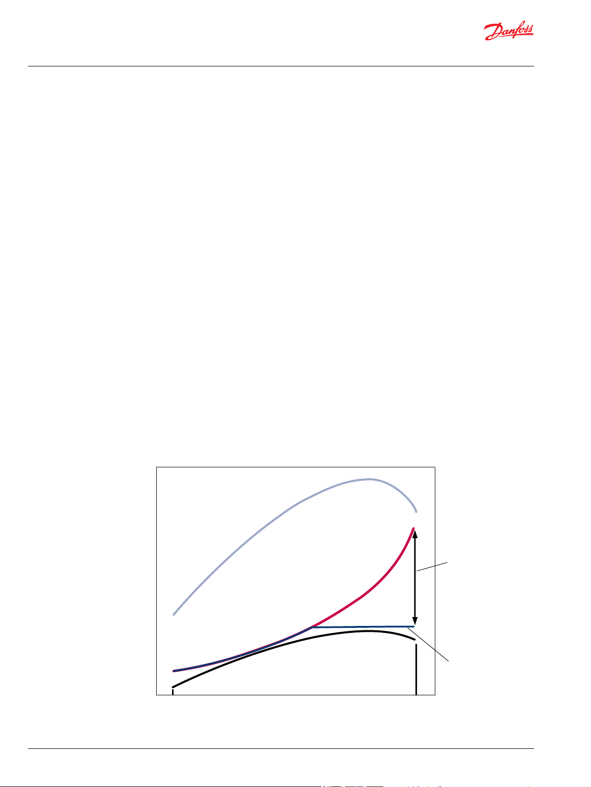
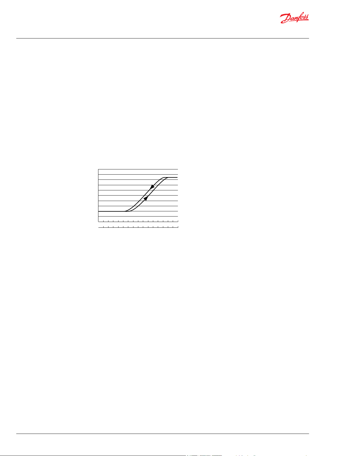
The power to drive a cooling fan rises as a cubic function of fan speed (doubling the fan speed requires
an eight-fold increase of input power). However, engine power and cooling demand decrease at higher
speeds. Because of this inverse relationship, a direct drive cooling fan must be sized to meet cooling
requirement at a relatively low engine speed and is therefore significantly oversized for cooling
requirements at higher speeds. Hydraulic fan drive systems allow fan speed to be trimmed so the fan can
be properly sized at low engine speeds without drawing excessive power at high speeds.
Power vs Engine Speed Curve
Feller bunchers
Forwarders
Harvesters
Log skidders
Buses
RV motorhomes
Garbage trucks
Sweepers
Marine
Oil and Gas drilling/Fracking
Mining
Fan systems are sized to provide required air flow at all engine speeds and operating conditions. Directdrive fans consume a great deal of power at higher engine speeds, without any advantage.
6 | © Danfoss | Sept 2018 520L0824 | BC00000115en-000403
Page 7
F
an speed
Fan standby speed
U
n
t
r
i
m
m
e
d
f
a
n
s
p
e
e
d
Trim at mid-range cooling demand
Set poin t
Trimmed fan speed
Engine speed
P101 275E
Technical Information
Hydraulic Fan Drive Systems
General Information
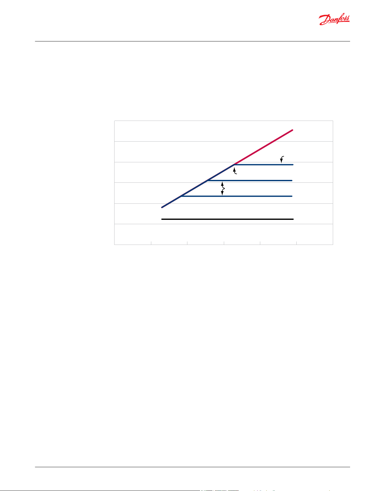
Trimmed and Standby Fan Speed
Under full cooling demand, maximum fan speed increases with engine speed, up to the set point of the
fan drive system (the point where further increase in speed yields no further gain). Beyond this point fan
speed does not increase, allowing greatly reduced power consumption compared to an untrimmed fan.
Under minimum cooling demand, standby fan speed can be set to provide very low, or minimal air flow.
Fan Speed vs Engine Speed
Flexible Mounting
Wide Range of Components
Basic Operation
Intelligent Control
The upper curves represent maximum cooling conditions; maximum fan speed is trimmed at the set
point. The lowest curve represents the standby condition; fan speed is maintained at a minimum value.
Hydraulic fan drives make it is possible to mount the radiator and fan just about anywhere on the vehicle.
This is advantageous in space conscious designs.
A fan drive system is sized to provide the required fan torque and speed. Danfoss has a wide range of
pumps, motors, controls, and sensors to meet your unique fan drive system needs.
In simplest terms, fan speed is controlled by regulating the amount of hydraulic oil passing through the
fan motor. The greater the flow, the greater the fan speed. The amount of flow is regulated based on one
or more inputs from the power system. Typically, engine coolant temperature is the main controlling
factor. Other system inputs may include hydraulic fluid temperature, charge air temperature and various
signals or switches. As inputs indicate a change in cooling demand, the system adjusts flow to the motor.
At the core of the Danfoss Fan Drive System is a controller that monitors relevant cooling parameters and
adjusts fan speed accordingly.
Fan Drive Controller
The Danfoss fan drive control system monitors cooling parameter inputs and provides an electronic
signal to a proportional hydraulic valve. The proportional valve relays a hydraulic signal either to the
©
Danfoss | Sept 2018 520L0824 | BC00000115en-000403 | 7
Page 8
205
0
200
400
600
800
1000
1200
1400
1600
1800
2000
170(F) 175 180 185 190 195 200
F
an speed (rpm)
Engine temperatur e
9580(C) 85 90
P101 276E
Technical Information
Hydraulic Fan Drive Systems
General Information
bypass valve on the motor or the displacement control of a variable displacement pump. Possible inputs
to the fan drive control system include engine coolant temperature, charge air temperature, engine or
transmission oil temperature, compartment temperature, ambient temperature, and various other
signals and switches. Also, many engine control systems provide a fan controlling signal or CAN message
which can serve as a cooling parameter input.
Balanced Fan Speed and Heat Generation
When an input, such as engine coolant temperature, rises above a predetermined level, signalling an
increase in cooling demand; fan speed is gradually increased. Coolant temperature and fan speed
continue to rise until heat generation and cooling are balanced. Under most conditions, this balance
occurs at a level below the maximum capability of the system.
Maximum fan speed is reached only under simultaneous conditions of maximum ambient temperature
and maximum engine load. These parameters are set as part of the cooling system design criteria.
Fan Speed Vs. Engine Temperature
Fan speed is increased as monitored temperature increases until balance is reached.
8 | © Danfoss | Sept 2018 520L0824 | BC00000115en-000403
Page 9
Microcontroller
(PLUS+1TM)
Filter
T3
T2
T1
Temperature
sensors
Gear pump
(SNP or D)
Fan drive
gear motor
(D or SGMY)
RESERVOIR
DIESEL ENGINE
P107 983E
Engine
Control
Module
CAN-BUS J1939
Engine Cooling Command
Technical Information
Hydraulic Fan Drive Systems
Fan Drive Systems
Modulating Fan Drive Systems
Monitoring various cooling system parameters enables the Danfoss modulating fan drive systems to
increase fan speed as required. As a modulating system, it ramps fan speed only to the level required,
providing only as much air flow as needed to maintain balance between heat generation and cooling.
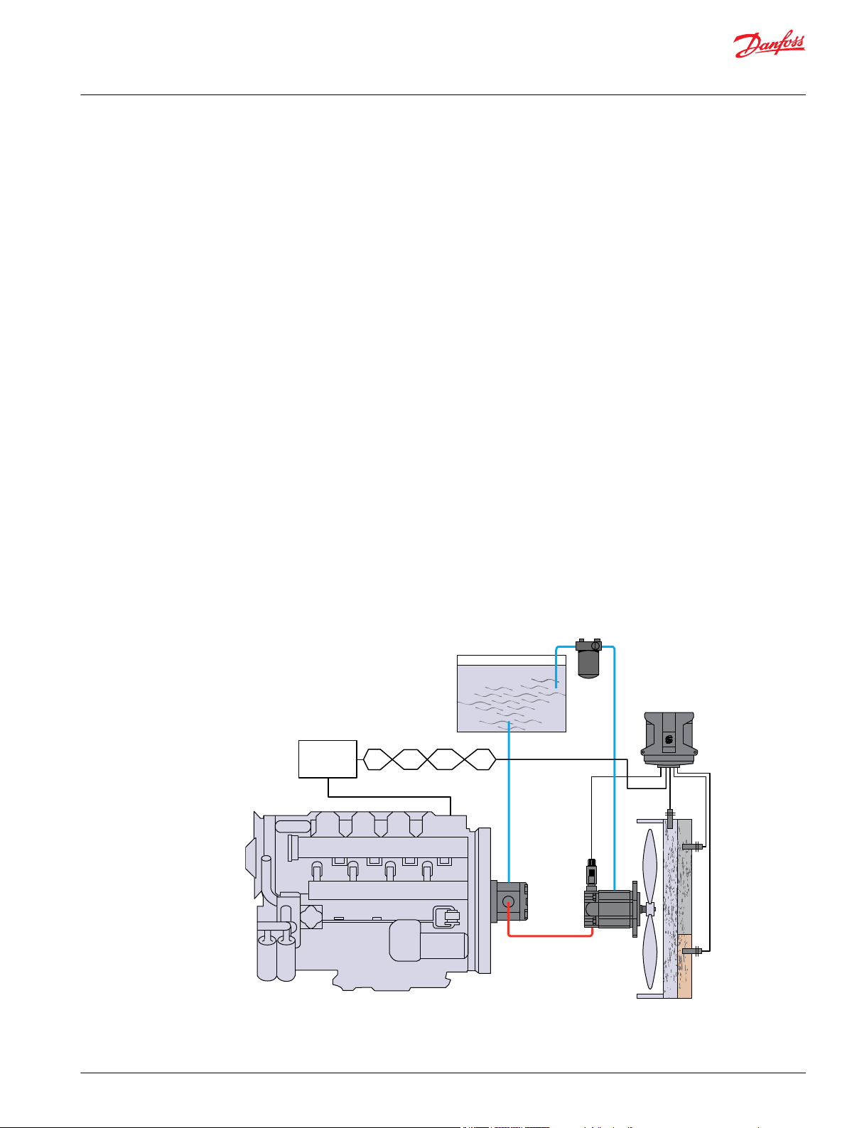
Gear Pump with Gear Motor and PLUS+1TM Fan Drive Controller
The pump receives oil directly from the reservoir through the inlet line. The output of the pump is
directed to a gear motor with an integral proportional relief valve.
The setting of the valve determines the maximum pressure in the system by bypassing oil (around the
motor’s gear set) directly to the return port of the motor. The proportional valve is normally closed and
requires the application of a PWM signal to reduce the bypass pressure. In a hydraulic fan drive system,
the pre-determined maximum pressure setting determines the maximum pressure to the motor, and the
maximum trim speed of the fan.
Applying a PWM signal to the valve allows the fan to run at speeds below its maximum trim speed,
regardless of the flow supplied by the pump.
Oil exiting the motor is directed back to the reservoir through a filter and a heat exchanger. Oil returning
to the reservoir must enter the reservoir well below the fluid level so air will not be entrained in the fluid.
The oil is diffused as it enters the reservoir to decelerate it to an acceptable level, to mix it with the fluid in
the reservoir, and to prevent the oil from flowing immediately back to the pump inlet. The return oil
should remain in the reservoir long enough to allow any entrained air in the fluid to rise to the surface
and dissipate back into the atmosphere. An anti-cavitation check valve prevents damage to the fan
motor in case of overrun. Fan overrun can occur when fan speed exceeds the speed commanded by the
system due to the fan windmilling in the vehicle’s air stream.
Gear Pump with PLUS+1TM Controller
PLUS+1TM System Illustration
©
Danfoss | Sept 2018 520L0824 | BC00000115en-000403 | 9
Page 10
T3
T2
T1
Temperature
sensors
RESERVOIR
Gear motor
(SNM)
Microcontroller
(PLUS+1TM)
Filter
DIESEL ENGINE
Variable pump
(Series 45)
P107 984E
RESERVOIR
Variable pump
(Series 45)
Selector
switch
Signal
lamp
Gear motor
(SNM)
Microcontroller
(PLUS+1TM)
Filter
DIESEL ENGINE
T3
T2
T1
Temperature
sensors
HIC
Cartridge valve
P107 985E
Technical Information
Hydraulic Fan Drive Systems
Fan Drive Systems
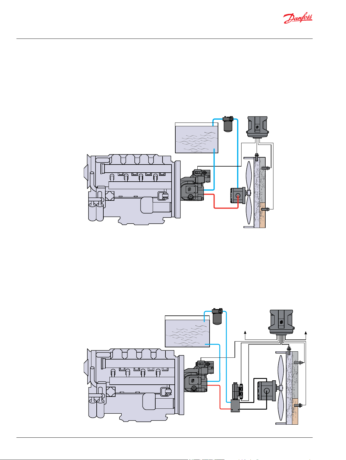
Variable Displacement Pump with Fan Drive Control
The variable displacement pump sends flow to the fan motor. Based on sensor and other inputs, the
microcontroller adjusts the proportional relief valve to regulate the pressure in the pilot port of the
pump’s load sensing control. Higher pressure in the pilot line results in increased flow to the fan motor.
The control has a pressure compensator feature which can be used to limit the fan’s trim speed. Trim
speed can also be set by software in the microcontroller.
Fan Drive Control System Illustration
Variable Displacement Pump and HIC Cartridge Valve
The system shown below is the same as the previous system with the addition of an electronically
controlled HIC cartridge valve between the pump and motor.
The HIC cartridge valve reverses the hydraulic flow to the motor, thus reversing the rotation of the fan.
This feature is commonly used to clean out the radiator if it becomes clogged with debris.
Variable Pump with HIC Cartridge Valve
10 | © Danfoss | Sept 2018 520L0824 | BC00000115en-000403
Page 11
T3
T2
T1
Temperature
sensors
RESERVOIR
Fixed displacement
piston motor
(S40 or S90)
Microcontroller
(PLUS+1TM)
Filter
DIESEL ENGINE
Piston pump
(H1 w/fan drive control)
P107 983E
Filter
Technical Information
Hydraulic Fan Drive Systems
Fan Drive Systems
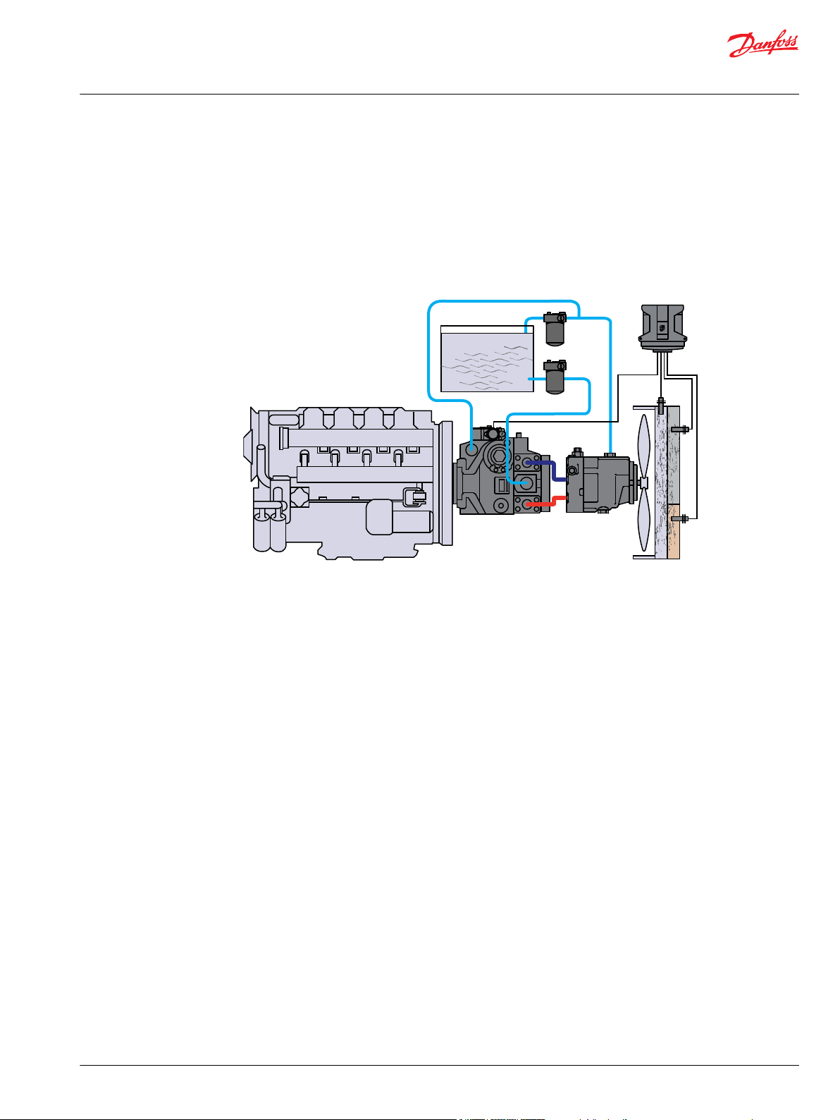
Closed Circuit System with Microcontroller
The variable displacement axial piston pump sends flow to the fixed displacement piston fan motor.
Based on temperature sensor and other inputs, the microcontroller regulates the displacement of the
axial piston pump. Higher coolant temperature results in increased flow to the fan motor. The pumps
displacement control has a pressure compensator feature which can be used to limit the maximum fan
trim speed in either direction. Trim speed can also be set by software in the microcontroller. The nature of
the closed-loop system prevents fan overrun. Zero fan speed is available on demand.
Variable Pump with Fixed Piston Motor
©
Danfoss | Sept 2018 520L0824 | BC00000115en-000403 | 11
Page 12
Technical Information
Hydraulic Fan Drive Systems
System Components
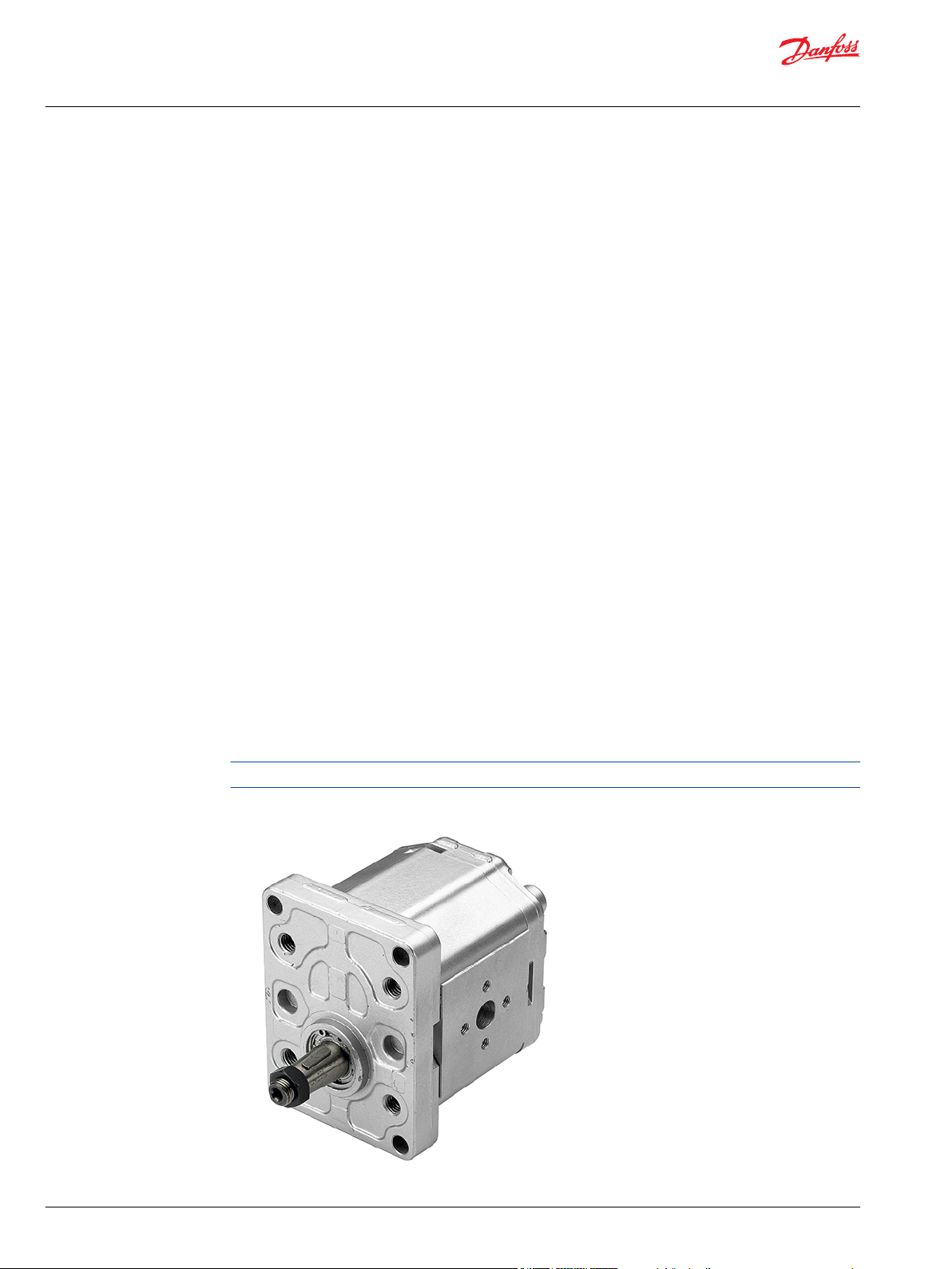
Gear Pumps
Danfoss offers gear pumps in a variety of models, sizes, capacities, and configurations. Integral priority
flow dividers are available which supply a constant flow for power assisted steering with the remainder
driving the fan drive motor.
Model Sizes and Capacities
Danfoss gear pumps are available in the following models and sizes.
Aluminum construction
•
•
Cast iron construction
•
Group 2
4 to 25 cm3/rev [0.24 to 1.53 in3/rev] displacement
Group 3
22 to 90 cm3/rev [1.34 to 5.49 in3/rev]
Group 2.5 (D Series)
7 to 45 cm3/rev [0.43 to 2.75 in3/rev]
Configurations
Single pump
•
Single pump with priority flow divider for power steering assist
•
Tandem pumps
•
Tandem pumps with priority flow divider for power steering assist
•
Multiple pumps (triple, quadruple, etc.)
•
Quadra-Flow pumps (digital displacement)
•
D Series pumps (single and tandem) are available with load sense and discrete flow options.
Group 2 aluminum gear pump
12 | © Danfoss | Sept 2018 520L0824 | BC00000115en-000403
Page 13
Technical Information
Hydraulic Fan Drive Systems
System Components
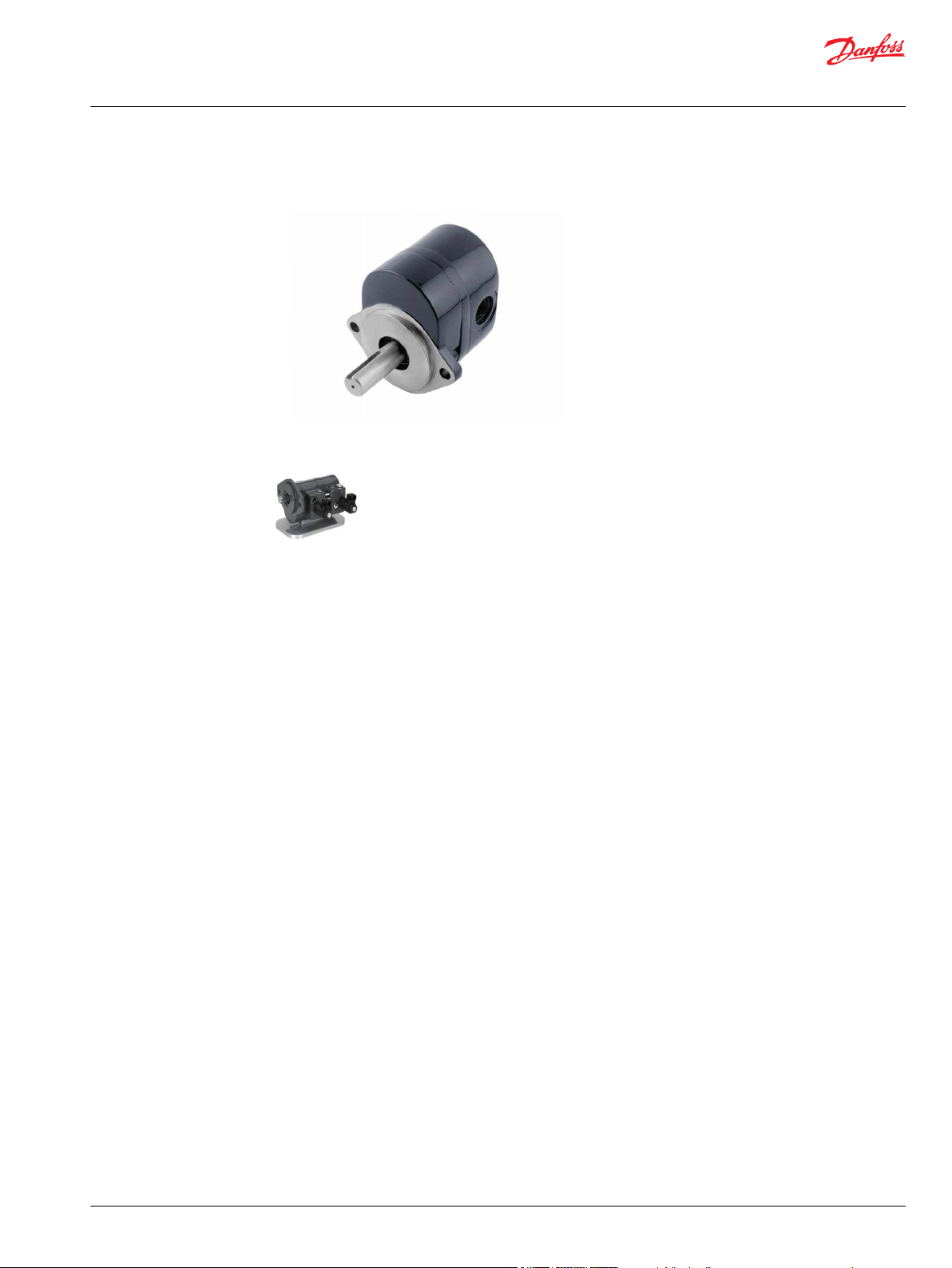
Group 2.5 D Series gear pump
Quadra-Flow gear pump
©
Danfoss | Sept 2018 520L0824 | BC00000115en-000403 | 13
Page 14
Technical Information
Hydraulic Fan Drive Systems
System Components
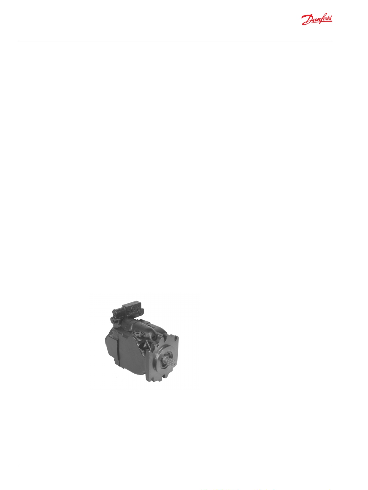
Series 45 Variable Displacement Axial Piston Pumps
Danfoss offers a complete family of variable displacement, open circuit, axial piston pumps. The Series 45
family offers a wide range of shafts, flanges, and porting options. Through drives are also available for
auxiliary pump drives. Load sensing (LS), pressure compensating (PC), remote pressure compensating
(RPC) and electro-proportional fan drive controls are available.
Frame K/L
•
25, 30, 38 and 45 cm3/rev [1.53, 1.83, 2.32, 2.75 in3/rev]
•
Operating pressures up to 260 bar [3770 psi]
•
Speeds to 3200 min-1(rpm)
Frame J
•
45, 51, 60, 65 and 75 cm3/rev [2.75 3.11, 3.66, 3.97, and 4.57 in3/rev]
•
Operating pressures to 310 bar [4495 psi]
•
Speeds to 2800 min-1(rpm)
Frame F
•
74 and 90 cm3/rev [4.52 and 5.49 in3/rev]
•
Operating pressures to 310 bar [4495 psi]
•
Speeds to 2400 min-1(rpm)
Frame E
•
100, 130, and 147 cm3/rev [6.10, 7.93 and 8.97 in3/rev]
•
Operating pressures to 310 bar [4495 psi]
•
Speeds to 2450 min-1(rpm)
Frame J
14 | © Danfoss | Sept 2018 520L0824 | BC00000115en-000403
Page 15
Technical Information
Hydraulic Fan Drive Systems
System Components
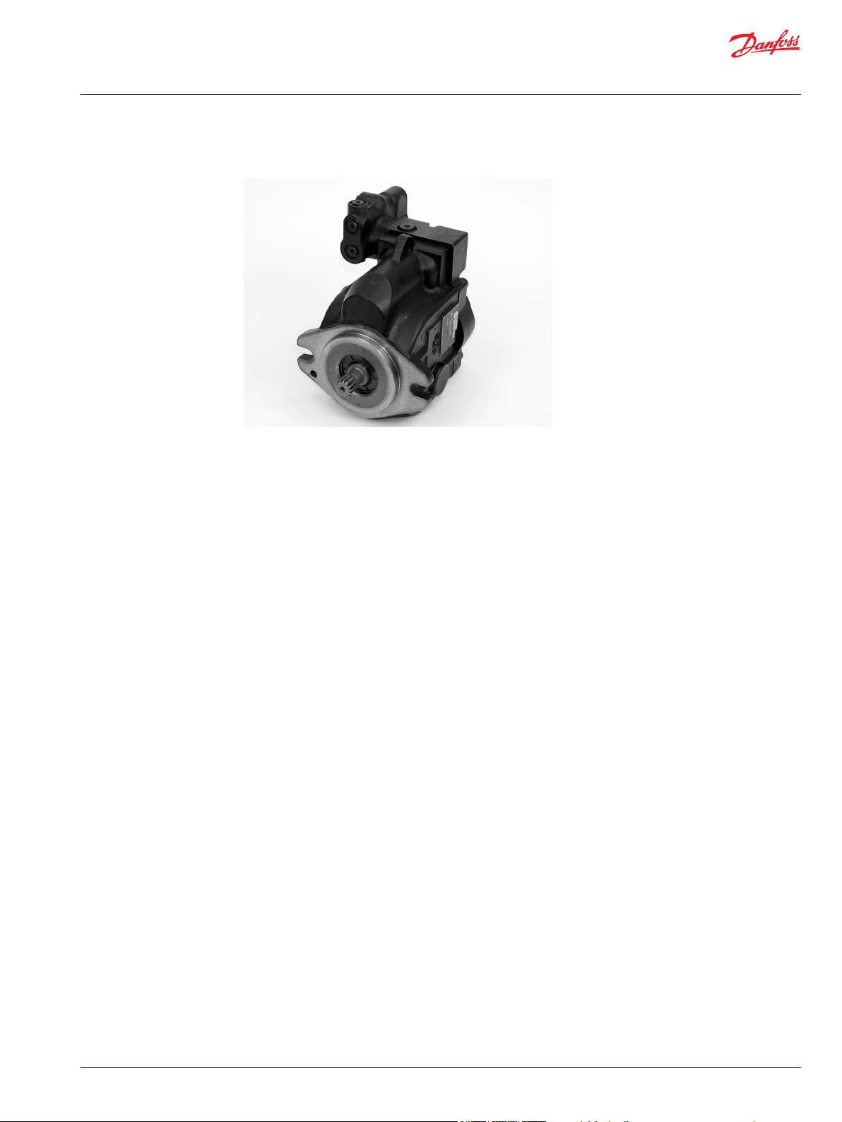
Frame K/L
Series 45 Fan Drive Control
The Series 45 fan drive control is an electric proportional control for Series 45 pumps. It controls the
pump based on various machine operating parameters. In a fan drive system, coolant temperature forms
the basis for pump control.
When the solenoid is de-energized, the pump operates in the high pressure standby (pressure
compensation) mode; when the solenoid is fully energized, the pump returns to the low pressure
standby mode of operation. This allows the system to minimize energy loss when the cooling system
does not require cooling fan operation, potentially using existing system control components
(temperature sensor or micro-controller).
The control is proportional. As the current applied to the solenoid increases, the regulated system
pressure gradually decreases until the full current is applied, achieving low standby pressure.
©
Danfoss | Sept 2018 520L0824 | BC00000115en-000403 | 15
Page 16
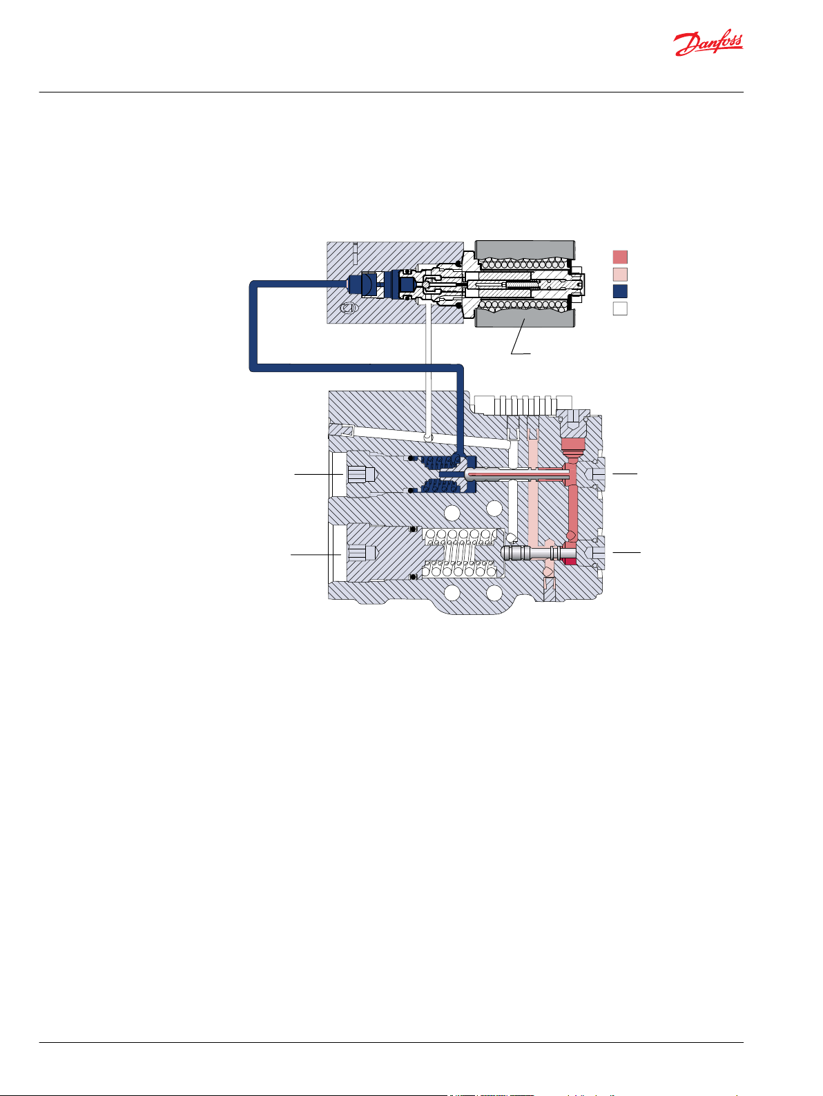
LS adjustment
PC adjustment
LS spool
PC spool
Proportional solenoid
P106 027E
System pressure
Pilot Pressure
Servo pressure
Drain
Technical Information
Hydraulic Fan Drive Systems
System Components
D Series Motor
D series fan drive motors are available in displacements from 17 cm3/rev [1.04 in3/rev]to 45 cm3/rev [2.75
in3/rev].
D series fan motors are PLUS+1 compliant.
16 | © Danfoss | Sept 2018 520L0824 | BC00000115en-000403
Page 17
Technical Information
Hydraulic Fan Drive Systems
System Components
D Series Motor
D Series Motor Technical Data
Ratings Units 17 19 21 23 25 29 32 36 38 41 45
Displacement cm3/rev 17.0 19.0 20.5 22.5 25.4 29.0 31.8 36.1 38.0 41.0 45.0
in3/rev 1.04 1.16 1.25 1.37 1.55 1.77 1.94 2.20 2.32 2.50 2.75
Rated pressure bar 276 276 276 276 276 276 276 276 276 241 210
psi 4000 4000 4000 4000 4000 4000 4000 4000 4000 3495 3045
Peak pressure bar 303 303 303 303 303 303 303 303 303 265 231
psi 4400 4400 4400 4400 4400 4400 4400 4400 4400 3843 3350
Speed at rated pressure maximum 3400 3400 3400 3400 3400 3400 3400 3400 3400 3000 3000
minimum* 600 600 600 600 600 600 600 600 600 600 600
Minimum shaft speed at 69 bar [1000 PSI] rpm 400 400 400 400 400 400 400 400 400 400 400
Standard Weight kg 8.53 8.66 8.80 8.94 9.07 9.38 9.53 9.84 9.93 10.16 10.43
lb 18.8 19.1 19.4 19.7 20.0 20.7 21.0 21.7 21.9 22.4 23.0
Mass moment of inertia of internal rotating
components
Theoretical torque at rated pressure N•m 65.7 73.4 79.2 87.0 98.2 112.1 122.9 139.6 146.9 138.4 132.4
Theoretical power at rated speed kW 23.4 26.1 28.2 31.0 35.0 39.9 43.8 49.7 46.1 43.5 41.6
x10-6 kg•m² 127 138 146 156 172 191 206 228 239 255 276
-6
x10
slug•ft²
lbf•ft 48.5 54.2 58.4 64.2 72.4 82.7 90.7 102.9 108.3 102.1 97.6
hp 31.2 34.9 37.6 41.3 46.6 53.2 58.4 66.3 61.1 58.0 55.5
94 102 107 115 127 141 152 168 176 188 204
©
Danfoss | Sept 2018 520L0824 | BC00000115en-000403 | 17
Page 18
Technical Information
Hydraulic Fan Drive Systems
System Components
D Series Motor Technical Data (continued)
Ratings Units 17 19 21 23 25 29 32 36 38 41 45
Case drain pressure bar 5.0 5.0 5.0 5.0 5.0 5.0 5.0 5.0 5.0 5.0 5.0
psi 72.5 72.5 72.5 72.5 72.5 72.5 72.5 72.5 72.5 72.5 72.5
* minimum speed at maximum pressure
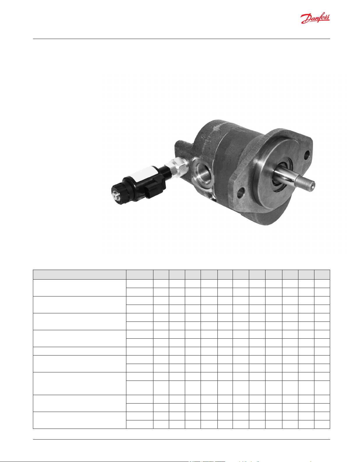
SGM2Y Motor
Group 2 fan drive motors are available in displacements from 8.4 cm3/rev [0.51 in3/rev]to 25 cm3/rev [1.54
in3/rev].
Configurations include European and SAE flanges; taper 1:8, 1:5, and straight shafts Ø15.875 mm [0.62 in].
Group 2 fan drive motors are PLUS+1 compliant.
SGM2Y Motor
SGM2Y technical data
Units Frame size
8.0 011 014 017 019 022 025
Displacement cm3/rev
[in3/rev]
Peak pressure bar [psi] 270 [3916] 270 [3916] 270 [3916] 250 [3626] 230 [3336] 200 [2900] 180 [2610]
Rated pressure 250 [3626] 250 [3626] 250 [3626] 230 [3336] 210 [3046] 180 [2610] 160 [2320]
Back pressure 150 [2176] 150 [2176] 150 [2176] 150 [2176] 130 [1885] 100 [1450] 100 [1450]
Maximum speed min-1 [rpm] 3500 3500 3500 3500 3500 3500 3500
Weight kg [lb] 4.73 [10.43] 4.83 [10.65] 5.03 [11.1] 5.18 [11.42] 5.23 [11.53] 5.33 [11.75] 5.53 [12.2]
Moment of inertia of
rotating components
Electrical connector model Deutsch DT 04-2P connectors (Protection rate IP 69K DIN 400050)
Electrical current signal A 0 to 1.1 A @ 12VDC, with coil resistance of 7.2 ohms @ 20°C [68°F]
PWM frequency Hz from 100 to 200
x 10-6 kg•m
[x 10-6 lbf•ft2]
8.4 [0.51] 10.8 [0.66] 14.4 [0.88] 16.8 [1.03] 19.2 [1.17] 22.8 [1.39] 25.2 [1.54]
2
32.4 [796] 38.4 [911] 47.3 [1122] 53.3 [1265] 59.2 [1405] 68.1 [1616] 74.1 [1758]
0 to 0.55 A @ 24VDC, with coil resistance of 28.8 ohms @ 20°C [68°F]
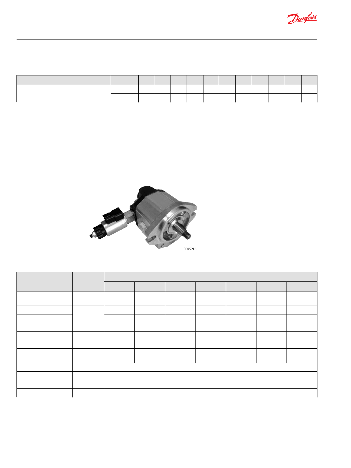
SGM3Y Motor
Group 3 fan drive motor available in displacements from 22.1 cm3/rev [1.34 in3/rev]to 44.1 cm3/rev [2.69
in3/rev].
Group 3 fan drive motors are PLUS+1 compliant.
18 | © Danfoss | Sept 2018 520L0824 | BC00000115en-000403
Page 19
Technical Information
Hydraulic Fan Drive Systems
System Components
SGM3Y Motor
SGM3Y technical data
Displacement cm3/rev
Peak pressure bar [psi] 210 [3046] 210 [3046] 210 [3046] 210 [3046] 210 [3046]
Rated pressure 190 [2756] 190 [2756] 190 [2756] 190 [2756] 190 [2756]
Maximum speed min
Weight kg [lb] 9.12 [20.11] 9.22 [20.33] 9.32 [20.55] 9.38 [20.68] 9.52 [21.0]
Moment of inertia
of rotating
components
Electrical connector model Deutsch DT 04-2P connectors (Protection rate IP 69K DIN 400050)
Electrical current
signal
PWM frequency Hz from 100 to 200
Units Frame size
022 026 033 038 044
22.1 [1.34] 26.2 [1.60] 33.1 [2.02] 37.9 [2.31] 44.1 [2.69]
[in3/rev]
Back pressure 120 [1740] 120 [1740] 120 [1740] 120 [1740] 120 [1740]
-1
[rpm]
-6
x 10
2
kg•m
-6
[x 10
lbf•ft2]
A 0 to 1.1 A @ 12VDC, with coil resistance of 7.2 ohms @ 20°C [68°F]
3500 2500 2500 2500 2500
198 [4699] 216 [5126] 246 [5838] 267.2 [6341] 294.2 [6981]
0 to 0.55 A @ 24VDC, with coil resistance of 28.8 ohms @ 20°C [68°F]
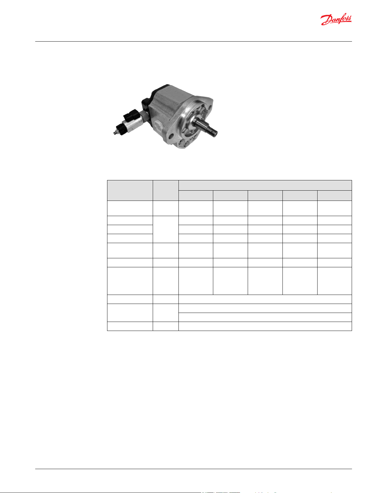
L/K Frame Axial Piston Motors
For higher power applications, Danfoss offers the L and K frame two position, axial piston motor. The KV
and LV motors can operate at two different displacements. Minimum displacement can be used when
high fan speed is required at low engine speed and maximum displacement can be used at high engine
speed. The K and L frame motors can also be used as single displacement motors.
This short, compact motor is configured ideally for installations requiring compact packaging and
optimized plumbing. All hydraulic ports are on one face of the motor. Axial or radial configurations are
available.
Mounting
SAE B-2 bolt and Danfoss cartridge
•
Shaft
SAE 0.875 diameter cylindrical and 1:8 taper keyed shafts
•
System Ports
©
Danfoss | Sept 2018 520L0824 | BC00000115en-000403 | 19
Page 20
Technical Information
Hydraulic Fan Drive Systems
System Components
•
Specifications
•
•
•
Control
•
•
•
Options
•
•
•
LV Motor
SAE O-ring boss, axial or twin radial locations
25, 30, 38 and 45 cm3/rev [1.52, 1.83, 2.14, 2.32 and 2.75 in3/rev] maximum displacements
Operating pressure up to 415 bar [6000 psi]
Speeds up to 5500 min-1(rpm)
Direct acting single line hydraulic displacement control
10 to 241 bar [150 to 3500 psi] shift pressure
Reverse Displacement Control (electric or hydraulic)
Speed sensor
Maximum displacement limiter
Integral over-pressure and anti-cavitation protection
20 | © Danfoss | Sept 2018 520L0824 | BC00000115en-000403
Page 21

Technical Information
Hydraulic Fan Drive Systems
System Components
LC Motor
PLUS+1TM Controllers
12 Pin Microcontroller
©
Danfoss | Sept 2018 520L0824 | BC00000115en-000403 | 21
Page 22

Technical Information
Hydraulic Fan Drive Systems
System Components
24 Pin Microcontroller
PLUS+1TM controllers and input/output expansion modules are designed to provide flexible, expandable,
powerful, and cost effective total machine management systems for off-highway vehicles. These modules
communicate with one another and other intelligent systems over a machine CAN (Controller Area
Network) data bus. PLUS+1TM hardware products are designed to be equally effective in a distributed
CAN network system, with intelligence in every node, or as stand-alone control for smaller machine
systems. PLUS+1TM systems are incrementally expandable: Additional modules can be easily added to the
machine CAN network to increase system capabilities or computational power.
Inputs
Each input pin allows one or more of these functional types. For pins with multiple functions, input
parameters are user programmable using PLUS+1TM GUIDE templates.
Digital (DIN)
•
Digital or Analog (DIN/AIN)
•
Digital or Analog or Frequency (DIN/AIN/FreqIN)
•
Analog or Temperature or Rheostat (AIN/Temp/Rheo)
•
Fixed Range Analog or CAN shield (AIN/CAN shield)
•
Outputs
PLUS+1TM control modules feature user-configurable universal output circuits. Output parameters are
configured using PLUS+1TM GUIDE templates. Refer to product data sheets for maximum current ratings
of individual modules. The following output types are supported:
•
Digital (DOUT)
•
PWM (PWMOUT)
•
Analog voltage suitable for driving Danfoss PVG valves (PVEOUT)
CAN Ports
All PLUS+1TM modules have CAN ports that conform to CAN 2.0b specifications, including CAN shield.
Temperature Sensors
The Danfoss family of analog temperature sensors is designed to operate in conjunction with Danfoss
Fan Drive Controls. The PLUS+1TM compliant sensors are thermistor-type temperature sensors.
22 | © Danfoss | Sept 2018 520L0824 | BC00000115en-000403
Page 23

Technical Information
Hydraulic Fan Drive Systems
System Components
Temperature sensors
Models
Two models are available: An air sensor typically used to measure engine charge air temperature, and a
liquid sensor typically used to measure engine coolant or oil temperature.
Features
Integrated connector and sensor body
•
Brass body construction
•
Anti-fouling air temperature sensor design
•
50° C to 125° C operating temperature
•
range, FDC software configurable
•
For proper operation, the air temperature sensor must be mounted at the top of the manifold pipe with
the sensor tip facing down.
Temperature versus resistance limits
Measured Temp, ° C
[°F]
50 [122] 810.9 ±5%
80 [176] 283.0 ±5%
100 [212] 152.9 ±8%
125 [257] 76.9 ±8%
PLUS+1 TM Compliance
The Danfoss temperature sensors are compliant with the larger microprocessors (for example the
MC050). The MC050 microprocessor has internal resistance in its four temperature inputs.
If you are using the Danfoss temperature sensors with the smaller microprocessors (for example the
MC012 and MC024), you will need to connect the sensors in series with an external resistor (Rv) as shown
in the following illustration.
Nominal Tolerance
Resistance, Ohms
©
Danfoss | Sept 2018 520L0824 | BC00000115en-000403 | 23
Page 24

Technical Information
Hydraulic Fan Drive Systems
System Components
Analog sensor voltage
For assistance in configuring the temperature sensors contact your Danfoss representative.
24 | © Danfoss | Sept 2018 520L0824 | BC00000115en-000403
Page 25

Based on SI units
= (l/min)
Input torque M = (N•m)
Input power P = (kW)
Motors
Based on SI units
Output torque M = (N•m)
Output power P = (kW)
Based on English units
= (US gal/min)
Input torque M = (lbf•in)
Input power P = (hp)
Based on English units
Output torque M = (lbf•in)
Output power P = (hp)
Vg • n • η
v
1000
Vg • ∆p
20 • π • η
m
Vg• n• ∆p
600 000 • η
m
Vg • n • η
v
231
Vg • ∆p
2 • π • η
m
Vg • ∆p • η
m
20 • π
Q • ∆p • ηt
600
Vg • ∆p • η
m
2 • π
Q • ∆p • η
t
1714
Pumps
Vg• n• ∆p
396 000 • η
m
Technical Information
Hydraulic Fan Drive Systems
System Design Parameters
Sizing Equations
Equations
Variables
SI units [English units]
Vg = Displacement per revolution cm3/rev [in3/rev]
pO = Outlet pressure bar [psi]
pi = Inlet pressure bar [psi]
∆p = pO - pi (system pressure) bar [psi]
n = Speed min-1 (rpm)
ηv = Volumetric efficiency
ηm = Mechanical efficiency
ηt = Overall efficiency (ηv • ηm)
SI unit formulas are based on cm3, bar, N, N•m, W.
English formulas are based on in3, psi, lbf•in, hp.
©
Danfoss | Sept 2018 520L0824 | BC00000115en-000403 | 25
Page 26

C
L
O
C
K
W
I
S
E
C
O
U
N
T
E
R
C
L
O
C
K
W
I
S
E
P106110
Model or Series
Belt Drive
(engine to pump)
Clockwise, Right hand
Counterclockwise, Anti-clockwise, Left hand
Manufacturer
Pump Drive
Pump Rotation
Speeds
Engine PTO
Ratio
:1
Low Idle
Governed
High Idle
RPM (rated)
RPM (rated)
RPM (max speed)
Input torque
limit:
P104 376E
US gal/min
bar
(maximum)
Controlled Flow Requirement
Steering Pressure
psi
l/min
Technical Information
Hydraulic Fan Drive Systems
System Design Parameters
System Design Data Form
Print this form. Fill in all the fields and check the appropriate check boxes. Fax the filled out form to your
Danfoss Power Solutions Technical Sales Representative.
Engine details
Power steering
(if applicable)
26 | © Danfoss | Sept 2018 520L0824 | BC00000115en-000403
Page 27

C
l
o
c
k
w
i
s
e
C
o
u
n
t
e
r
c
l
o
c
k
w
i
s
e
P101 344E
Model or Series
mm
Manufacturer
Fan Diameter
in
At speed
kW
Fan Input Power
HP
rpm
Fan Rotation
(viewed on motor shaft, see illustration)
Clockwise
Counterclockwise
Fan Trim Speed
rpm
Set Point at Fan Trim Speed
(engine speed where max heat load occurs)
rpm
Coolant Temperature at Fan Trim Speed
(coolant temp where max fan speed is required)
°F
°C
Note: To properly size and specify a fan drive system, fan power requirements must be stated as accurately as possible. Fan power requirements
can be determined from fan curves supplied by the manufacturer. Radiator and cooler manufacturers will supply air flow requirements based
on heat loads. Air flow information must include accurate air flow and static pressure to determine correct fan power requirements.
P104 377E
Single Input
Electro-Hydraulic Modulating Electro-Hydraulic ON/OFF
Multiple Inputs
P104 378E
US gal
Reservoir Capacity
liter
Technical Information
Hydraulic Fan Drive Systems
System Design Parameters
Fan information
Control preference
Reservoir
©
Danfoss | Sept 2018 520L0824 | BC00000115en-000403 | 27
Page 28

P104 379E
at 40° C [104°F]
Hydraulic Fluid Type
Viscosity
cSt
Maximum Fluid Temperature
°F
°C
SUS
at 100° C [212°F]
P104 380E
Inlet Line
Filter Position
Pressure Line
(recommended)
Return Line
Filter Rating
Full Flow
Filter Flow
Partial Flow
micron
x ratio
Note: Do not locate the filter cartridge inside the reservoir. This reduces the reservoir capacity and reduces the dwell time (the time the oil
spends in the resrevoir). It also increases the potential for damage to the hydraulic components due to aeration of the oil.
Technical Information
Hydraulic Fan Drive Systems
System Design Parameters
Fluid
Filtration
28 | © Danfoss | Sept 2018 520L0824 | BC00000115en-000403
Page 29

Technical Information
Hydraulic Fan Drive Systems
Installation Guidelines
Pumps
Pump Drives
Where possible, avoid radial and axial loads on the pump drive.
For in-line drives, place a suitable drive coupling between the prime mover (e.g. engine) and the pump
input shaft to remove radial and axial load potential. For belt driven pump applications an outrigger
bearing may be required to relieve the pump of radial loads. Outrigger bearings are available with ball or
roller bearing support for such applications. For Power Take Off (PTO) drives (where an external gear is
assembled to the pump), and for belt driven pump applications, consult your Danfoss representative.
In many applications the limiting factor for driving a pump is available torque. Pump drive shafts have a
torque limit based on material, design and system pressure. Likewise, pump drives such as air
compressors with PTOs also have torque limits. When planning to drive a pump on the back of an air
compressor, first check with the compressor supplier to understand their product torque limitations.
Most compressors do not have a constant torque capability across their speed range. Typically, the
torque capability of a compressor is lower at low engine speeds and increases to a speed where the
capability remains constant.
A number of pump drive shafts are generally available across the Danfoss product range. Consider
driveshaft selection carefully.
Motors
Pump Inlet
When designing the inlet portion of the hydraulic circuit, it is important to keep the pump inlet pressure
within published limits. To reduce the chances of inlet cavitation problems, observe the following
guidelines:
Position reservoir outlet above the pump inlet level whenever possible.
•
Make the inlet line (hose and fittings) as straight and as short as possible without inducing bending or
•
stress loads onto the inlet port.
Size the inlet line to keep fluid velocities and inlet pressure within the limits published in the
•
individual product literature.
To reduce the chances of port fitting leakage, we recommend using SAE split flange or O-ring boss
•
ports whenever possible.
Pump Outlet
•
Make the outlet line (hose and fittings) as straight and as short as possible without inducing bending
or stress loads onto the outlet port.
•
Ensure the outlet line is sized to keep fluid velocities within the limits published in the individual
product literature.
•
To reduce the chances of port-fitting leakage we recommend using SAE split flange or O-ring boss
ports whenever possible.
SGM2YN and SGM3YN Fan Drive Motors
SGM2Y and SGM3Y fan drive motors have the proportional solenoid bypass relief valve built into the rear
cover. Electrical connector is Deutsch DT 04-2P. Mount the motor so the relief valve is below the reservoir
oil level. Keep the relief valve in a horizontal position.
D Series Fan Drive Motors
D series fan drive motors are available with an integrated proportional or standard relief valve. Mount the
motor so the relief valve is below the reservoir oil level. Keep the relief valve in a horizontal position.
©
Danfoss | Sept 2018 520L0824 | BC00000115en-000403 | 29
Page 30

Technical Information
Hydraulic Fan Drive Systems
Installation Guidelines
L and K Variable Motors
L and K variable motors do not have over-pressure protection or an anti-cavitation valve integrated into
the motor. Both valve functions need to be provided externally.
L and K variable motors may be applied in open circuit systems without external back-pressure valves, as
long as the motor case pressure does not exceed the outlet pressure by more than 0.5 bar [7 psi].
Typically the motor's maximum displacement is used when the system is sized for maximum cooling
when the engine is at Full Load High Idle speed. The motor's minimum displacement is selected to
provide improved cooling when the engine is at its low idle speed.
Reverse Displacement Motors
The Reverse Displacement Motor is a unique design variation of the L and K variable motors.
It has been designed to reverse the direction of fan rotation without using an externally mounted four-
way directional control valve.
The motor is switched from maximum displacement in the forward direction to maximum displacement
in the reverse direction with an integrated solenoid valve.
Over-pressure protection and an anti-cavitation valve are integrated into the motors endcap.
Series 40 Fixed Displacement Motors
Series 40 motors are available with over-pressure protection and an anti-cavitation valve in a
unidirectional open circuit configuration.
They may be applied in open circuit systems without external back-pressure valves as long as the motor
case pressure does not exceed the outlet port pressure by more than 0.5 bar [7.0 psi].
Bi-directional open circuit operation is available, provided that a four-way directional control valve is
located between the pump and the motor.
Series 90 Fixed Displacement Motors
Series 90 fixed displacement motors are available without over-pressure protection or an anti-cavitation
valve in an open circuit configuration.
They may be applied in open circuit systems without external back-pressure valves, but
thrust, case pressure, and maximum shaft speed limits must be respected. (Consult your Danfoss
Technical Sales Representative for assistance when specifying a Series 90 fixed displacement motor in an
open circuit application.
specific axial
30 | © Danfoss | Sept 2018 520L0824 | BC00000115en-000403
Page 31

Technical Information
Hydraulic Fan Drive Systems
Installation Guidelines
Controls
PLUS+1TM controller
The Plus+1TM controller is designed to control many different hydraulic devices. Mount the Plus+1
TM
controller in a convenient, out of the way, location. A diagnostic connector is required to connect to the
Plus+1TM controller. Mount the connector in an easily accessible location in the operators cabin. Follow
the wiring guidelines found in Plus+1TM module technical literature.
Series 45 Fan Drive Controls
In Danfoss open circuit fan drives, fan speed is regulated by controlling the system pressure differential
across the fan motor. In Series 45 pumps, this is provided by using the Electric Proportional Control
variation. The Electric Proportional Control consists of a proportional solenoid integrated into the Remote
Pressure Compensated control housing. This control provides an output pressure proportional to the
current supplied to the solenoid and allows the pump to be operated at any pressure limit between the
load sense and pressure compensation settings by varying the current sent to the solenoid. Both
Normally Closed and Normally Open control configurations are available. The Normally Closed
configuration is usually applied in system cooling fan installations. It is desireable that the fan
fail to full
speed if there is an interruption of the electrical command to the solenoid, for any reason.
H1 Pump with Fan Drive Control
A fan drive control option is available for the H1 family of high power, closed circuit, variable
displacement pumps. The H1 Fan Drive Control is compatible with the PLUS+1TM controller and the fan
drive application block. The Fan Drive Control is designed with a single solenoid and uses a single control
input to regulate both the fan speed and direction of rotation.
When the pump speed is at the design set point, fan speed required for the desired cooling capacity is
determined by the pump's displacement. In many systems, the fan's speed at this condition may be close
to its maximum design speed. If the pump speed increases beyond the set point and the pump is
commanded to maximum displacement; then the fan speed will increase in proportion to the pump
speed ratio and the pressure drop across the fan motor will increase in proportion to the square of the
pump speed ratio. To prevent this from happening, the system designer is encouraged to limit the
maximum fan speed in each direction of rotation by adjusting the set pressure of the Pressure Limiters
for both directions of rotation.
The Fan Drive Control (FDC) has limitations on the maximum servo delta pressure developed, compared
to other types of controls, and so there are limitations to the operating conditions which can be achieved
in the various frame size H1 pumps. Typical fan drive systems are unusual in that they achieve peak
pressure only at high flows, so it is important that FDC equipped pumps not be applied beyond the
specified limits. (Refer to Fan Drive Design Guidelines 520L0926, Appendix H, for additional information,
or contact your Danfoss Technical Sales Representative for assistance.)
Fan drives are sized with reserve pump capacity so that peak fan speed can be maintained even when
engine speed is reduced, as illustrated below. This is a feature that is unique to the Danfoss H1 Fan Drive
Control; it allows the system to maintain a nearly constant fan speed without the need for additional
control algorithms in the fan drive controller. In this example, representing an engine lugging condition
(engine speed change of 20%), there was no significant reduction in fan speed.
©
Danfoss | Sept 2018 520L0824 | BC00000115en-000403 | 31
Page 32

3.0
RPM
x 10
Input speed
2.9
2.8
2.7
2.6
2.5
2.4
2.3
2.2
2.1
2.0
1.9
1.8
1.7
1.6
1.5
1.4
1.3
1.2
1.1
1.0
0.9
0.8
0.7
0.6
0.5
0.4
0.3
0.2
0.1
0.0
0
40
80
120
160
200
240
280
320
360
400
-40
-80
-120
-160
-200
-240
-280
-320
-360
-400
Bar
3
Degrees
0
2
4
6
8
10
12
14
16
18
20
-2
-4
-6
-8
-10
-12
-14
-16
-18
-20
0
1
2
3 4 5
7
8
9
10
11
12 13
14
15
16
17
18
19 20
6
Fan drive speed
Swashplate Angle
MA_MB_System_Press
M4_M5_Servo_Press
P108679
Bar
30
26
22
18
14
10
2
-14
-18
6
0
-2
-6
-10
-22
-26
-30
28
24
20
16
12
8
4
-4
-8
-12
-16
-20
-24
-28
Seconds
C
Technical Information
Hydraulic Fan Drive Systems
Installation Guidelines
Prime Mover Speed Change (2500 - 2000 - 2500 rpm)
System
Filtration
To prevent premature wear, it is imperative that only clean fluid enters the pump and hydraulic circuit. A
filter capable of controlling the fluid cleanliness to class 22/18/13 (per ISO 4406-1999) or better, under
normal operating conditions, is recommended. At initial start up, the system can be at Class 25/22/17 but
should not be run at high speed or pressure until the Class 22/18/13 is achieved through filtration. Since
the filter must be changed at regular intervals, the filter housing should be located in an accessible area.
32 | © Danfoss | Sept 2018 520L0824 | BC00000115en-000403
Appropriate filter change intervals may be determined by test or by gauges indicating excessive pressure
drop across the filter element.
For more information refer to Design Guideline for Hydraulic Fluid Cleanliness, Technical Information
520L0467.
Operating Temperatures
With Buna seals and normal operating conditions, the system temperature should not exceed 82 °C [180
°F] except for short periods to 93 °C [200 °F]. With optional Viton elastomer, the system may be operated
at continuous temperatures up to 107°C [225°F] without damage to the hydraulic components.
Caution
Operation in excess of 107 °C [225 °F] may cause external leakage or premature unit failure.
Fluids
A mineral based fluid is recommended that includes additives to resist corrosion, oxidation and foaming.
The oil should have a maximum viscosity commensurate with system pressure drop and pump suction
pressures. Since the fluid serves as a system lubricant, as well as transmitting power, careful selection of
the fluid is important for proper operation and satisfactory life of the hydraulic components. Hydraulic
Page 33

Technical Information
Hydraulic Fan Drive Systems
Installation Guidelines
fluids should be changed at appropriate intervals determined by test, supplier, or by change in color, or
odor, of the fluid.
Every 10°C [18°F] rise in continuous reservoir temperature over 80°C [176 °F] decreases the life of the oil
by ½.
For additional technical information on hydraulic fluids refer to Hydraulic Fluids and Lubricants 520L0463
Technical Information Bulletin and specific product technical bulletins.
For information relating to biodegradable fluids, see Danfoss publication Experience with Biodegradable
Hydraulic Fluids 520L0465 or consult the Danfoss Technical Services Department.
©
Danfoss | Sept 2018 520L0824 | BC00000115en-000403 | 33
Page 34

P106 103E
74.20
[2.92]
63.39
[2.50]
45.47
[1.79]
Illustration of left-hand (CCW) rotation
(SAE B mount available)
Priority flow port (CF)
3/4-16 UNF-2B SAE Str. thd.
for 1/2 in. O.D. tube
D
C
B
SAE B 13T:
*Except as noted
13 Tooth spline, 16/32 pitch
30° Pressure angle
Flat root side fit
Per ANSI B92.1-1970. Class 7
22.07
21.82
Ø
[0.869]
[0.859]
29.97
[1.18]
Eff. spline
39.91
[1.57]
Excess flow port (EF)
7/8-14 UNF-2B SAE Str. thd.
for 5/8 in. O.D. tube
47.75
[1.88]
133.87
[5.27]
20.32
[0.80]
Inlet port
1 5/16-12 UN-2B SAE Str. thd.
for 1 in. O.D. tube
12.45
[0.49]
10.41
[0.41]
6.1
[0.24]
82.55
82.50
[3.250]
[3.248]
Ø
A
106.38
[4.19]
95.5
[3.76]
Ø
53.17
[2.09]
11.18
[0.44]
2X R
20.63
[0.81]
22.55
[0.89]
61.76
[2.43]
41.15
[1.62]
11.68
[0.46]
2X Ø
Dimensions in mm [in]
*
Technical Information
Hydraulic Fan Drive Systems
Installation Drawings
D Series Pumps
D Series pump counterclockwise (CCW) rotation
For specifications and measurements for A, B, C, and D, refer to the folowing table.
34 | © Danfoss | Sept 2018 520L0824 | BC00000115en-000403
Page 35

P106 104E
74.60
[2.94]
63.39
[2.50]
45.47
[1.79]
Illustration of right-hand (CW) rotation
(SAE B mount available)
Priority flow port (CF)
3/4-16 UNF-2B SAE Str. thd.
for 1/2 in. O.D. tube
D
C
B
21.12
[0.83]
Excess flow port (EF)
7/8-14 UNF-2B SAE Str. thd.
for 5/8 in. O.D. tube
47.75
[1.88]
133.87
[5.27]
12.45
[0.49]
10.41
[0.41]
6.1
[0.24]
82.55
82.50
[3.250]
[3.248]
Ø
106.38
[4.19]
95.5
[3.76]
Ø
53.19
[2.09]
11.18
[0.44]
2X R
61.27
[2.41]
18.09
[0.71]
80.55
[3.17]
11.68
[0.46]
2X Ø
SAE A 11T:
*Except as noted
11 Tooth spline, 16/32 pitch
30° Pressure angle
Flat root side fit
Per ANSI B92.1-1970. Class 7
or better
18.64
18.52
Ø
[0.734]
[0.729]
26.42
[1.04]
Eff. spline
20.32
[0.80]
Inlet port
1 5/16-12 UN-2B SAE Str. thd.
for 1 in. O.D. tube
38.11
[1.50]
A
Dimensions in mm [in]
*
Technical Information
Hydraulic Fan Drive Systems
Installation Drawings
D Series Pump Clockwise (CW) Rotation
Nominal pump
displacement
cm3/rev
[in3/rev]
7.0 [0.43] 276 [4000] 303 [4400] 3400 80.5 [3.17] 92.0 [3.62] 94.5 [3.72] 116.1 [4.57]
Maximum
continuous
pressure
bar [psi]
9.5 [0.58] 276 [4000] 303 [4400] 3400 82.9 [3.27] 94.4 [3.72] 96.9 [3.82] 118.5 [4.67]
12.6 [0.77] 276 [4000] 303 [4400] 3400 86.1 [3.39] 97.5 [3.84] 100.1 [3.94] 121.7 [4.79]
14.3 [0.87] 276 [4000] 303 [4400] 3400 87.8 [3.46] 99.2 [3.91] 101.7 [4.01] 123.3 [4.86]
17.0 [1.04] 276 [4000] 303 [4400] 3400 90.4 [3.56] 101.9 [4.01] 104.4 [4.11] 126.0 [4.96]
©
Danfoss | Sept 2018 520L0824 | BC00000115en-000403 | 35
Maximum
pressure
bar [psi]
Maximum speed
min-1 (rpm)
A
mm [in]
B
mm [in]
C
mm [in]
D
mm [in]
Page 36

P108899
Inlet port
Outlet port
145.5
[5.73]
132.6
[5.22]
198.6
[7.82]
75.7
[2.98]
151.4
[5.96]
Technical Information
Hydraulic Fan Drive Systems
Installation Drawings
Nominal pump
displacement
cm3/rev
[in3/rev]
Maximum
continuous
pressure
bar [psi]
Maximum
pressure
bar [psi]
Maximum speed
min-1 (rpm)
A
mm [in]
B
mm [in]
C
mm [in]
19.0 [1.16] 276 [4000] 303 [4400] 3400 92.5 [3.64] 103.9 [4.09] 106.4 [4.19] 128.0 [5.04]
20.5 [1.25] 276 [4000] 303 [4400] 3400 94.0 [3.70] 105.4 [4.15] 108.0 [4.25] 129.6 [5.10]
22.5 [1.37] 276 [4000] 303 [4400] 3400 95.8 [3.77] 107.3 [4.22] 109.8 [4.32] 131.4 [5.17]
25.4 [1.55] 276 [4000] 303 [4400] 3400 98.8 [3.89] 110.2 [4.34] 112.8 [4.44] 134.4 [5.29]
29.0 [1.77] 276 [4000] 303 [4400] 3200 102.4 [4.03] 113.8 [4.48] 116.4 [4.58] 138.0 [5.43]
31.8 [1.94] 276 [4000] 303 [4400] 3000 105.2 [4.14] 116.6 [4.59] 119.1 [4.69] 140.7 [5.54]
36.0 [2.20] 241 [3500] 265 [3850] 2750 109.4 [4.31] 120.9 [4.76] 123.4 [4.86] 145.0 [5.71]
38.0 [2.32] 228 [3300] 250 [3630] 2750 111.4 [4.39] 122.8 [4.84] 125.4 [4.94] 147.0 [5.79]
41.0 [2.50] 207 [3000] 228 [3300] 2500 114.4 [4.50] 125.8 [4.95] 128.4 [5.05] 150.0 [5.90]
45.1 [2.75] 190 [2750] 209 [3025] 2500 118.6 [4.67] 130.1 [5.12] 132.6 [5.22] 154.2 [6.07]
Quadra-Flow Pump
D
mm [in]
36 | © Danfoss | Sept 2018 520L0824 | BC00000115en-000403
Page 37

CF
EF
P106105
P107897
CF
EF
LS
Technical Information
Hydraulic Fan Drive Systems
Installation Drawings
D Series Pumps with Priority Flow Schematic
D Series Pump with Load Sensing Schematic
©
Danfoss | Sept 2018 520L0824 | BC00000115en-000403 | 37
Page 38

P108900
P107 882E
CW motor shown. For CCW motor, valve is on the opposite side.
B
44.4
[1.75]
85.1
[3.35]
A
C
Motor is also
available with
cavities only
(no valve)
20.32
[0.8]
170.0
[6.69]
2 pin
Deutsch
connector
14.23
Ø
[0.56]
88.9
[3.50]
44.4
[1.75]
External drain - drive side
Inlet port and outlet port
sized identically
External drain - idler side
Technical Information
Hydraulic Fan Drive Systems
Installation Drawings
Quadra-Flow Schematic
D Series Gear Motor
D Series Motor Dimensions
Dimensions Units 17 19 21 23 25 29 32 36 38 41 45
DimensionAmm 88.9 90.9 92.5 94.2 97.3 100.8 103.6 107.7 109.7 112.8 117.1
in 3.50 3.58 3.64 3.71 3.83 3.97 4.08 4.24 4.32 4.44 4.61
Dimension B mm 91.7 93.8 95.3 97.0 100.1 103.6 106.4 110.7 112.5 115.6 119.9
in 3.61 3.69 3.75 3.82 3.94 4.08 4.19 4.36 4.43 4.55 4.72
Dimension C mm 154.4 156.5 158.0 160.0 162.8 166.4 169.2 173.5 175.5 178.6 182.6
in 6.08 6.18 6.22 6.30 6.41 6.55 6.66 6.83 6.91 7.03 7.19
Dimensions in table are maximum dimensions.
38 | © Danfoss | Sept 2018 520L0824 | BC00000115en-000403
Page 39

Inlet
Outlet
26
F
Drain: 9/16–18UNF–2B
(SAE J1926/1 O-Ring boss)
12.7 [0.5] min. full thread
G M6-6H
12 [0.47] min.
full thread
P005 400E
Connector: Deutsch DT 04-2P
Voltage: 12V DC (Current 1.1 A)
24V DC (Current 0.55 A)
PWM 100-200 Hz
[1.02 ±0.04
]
[0.62
±0.02
]
89 max
[3.504 max.]
92 max
[3.622 max.]
156 max
[6.142 max.]
12.5
[ 0.49 ]
B
A
D
15.7
Ø 80
[
Ø3.15
]
-0.002
-0.004
-0.06
-0.106
X
7.2
±1
±1
±0.039
±0.25
±0.5
±0.5 [±0.02]
E
+0.5
0
±1[±0.04]
B
±1[±0.04]
C
+1.5 [+0.059] max
[0.28 ±0.01]
±0.2 [±0.008]
R 0.8 max.
[0.03 max.]
45
o
[0.62
±0.02
]
15.7
±0.5
Ø 0.75
X
120 [4.72] max.
103 [4.055] max.
(100 [3.94])
65.5
[2.59]
72
[2.83]
34.5
[1.36]
9
+0.5
0
[0.35 ]
+0.02
0
36.2 max.
[1.425 max.
]
67.6 max.
[2.66 max.
]
+0.02
0
][
Valve type: PRV10–IS2
CW motor shown. For CCW motor, valve is on the opposite side.
Technical Information
Hydraulic Fan Drive Systems
Installation Drawings
SGM2YN Gear Motor
02AA
©
Danfoss | Sept 2018 520L0824 | BC00000115en-000403 | 39
SGM2YN - 02AA dimensions
Frame size 8.0 011 [0.67] 014 [0.95] 017 [1.04] 019 [1.16] 022 [1.34] 025 [1.53]
Dimension
mm [in]
Inlet port D 7/8-14 UNF-2B (SAE J1926/1 O-ring boss); 16.7 [0.66] min. full thread
A 47 [1.85] 49 [1.93] 52 [2.05] 54 [2.13] 56 [2.17] 59 [2.32] 61 [2.40]
B 95.5 [3.76] 99.5 [3.91] 105.5
C 118.5
[4.66]
122.5
[4.83]
[4.15]
128.5
[5.05]
109.5 [4.31] 113.5
132.5 [5.22] 136.5
[4.47]
[5.37]
119.5
[4.70]
142.5
[5.61]
123.5
[4.86]
146.5
[5.77]
Page 40

M12x1.25-6g
11.5 [0.453] min.
full thread
13
±0.5
[0.51 ±0.02]
3.7 max
[0.14 max]
5.7
±0.75
[0.22 ±0.029]
16.5
±0.75
[0.65 ±0.029]
A-A
Detail ‘P’
P
Ø 0.35
X
90 ±0.25
[3.54
±0.01]
[0.118 ]
3
0
-0.025
0
-0.001
[0.354 ]
9
+0.3
-0.1
+0.012
-0.004
[Dia 0.687]
Ø 17.46
1: 5
A
H
A
38 ±1
[1.5 ±0.04]
(19.3)
([0.76])
Inlet D
(SAE J1926/1 O-Ring boss)
16.7 [0.66] min. full thread
Detail ‘H’
P005 401E
39.5
±0.25
[1.555
±0.01]
Ø 34 [Dia 1.34]
Depth 5 [0.2] max
Technical Information
Hydraulic Fan Drive Systems
Installation Drawings
SGM2YN - 02AA dimensions (continued)
Outlet port E 15 [0.59] 20 [0.79]
Frame size 8.0 011 [0.67] 014 [0.95] 017 [1.04] 019 [1.16] 022 [1.34] 025 [1.53]
F 35 [1.38] 40 [1.57]
G M6-6H; 12[0.47] min. full thread
Drain port 9/16 18UNF-2B (SAE J1925/1 O-ring boss) 12.7 [0.50] min. full threads
For more information regarding SGM2Y gear motors, refer to SGM2Y and SGM3Y Fan Drive Motors
Technical Information 11040345.
40 | © Danfoss | Sept 2018 520L0824 | BC00000115en-000403
Page 41

Inlet D
26
Outlet E
(SAE J1926/1 O-Ring boss)
F min. full thread
Drain: 9/16–18UNF–2B
(SAE J1926/1 O-Ring boss)
12.7 [0.5] min. full thread
Valve Type: PRV10-IS2
P005 402E
[1.02 ±0.04 ]
[0.62
±0.02
]
89 max
[3.504 max.]
12
[ 0.47 ]
B
A
15.7
6.35
±1
±1
±0.04
-0.5
0
-0.02
0
±0.5
±0.5 [±0.02]
±1 [±0.04]
C
+1.5 [+0.06] max.
[0.25 ]
R 0.8 max.
[0.03 max.]
[0.62
±0.02
]
15.7
±0.5
Ø 0.75
X
36.2 max.
[1.43] max.
19.5 max.
[0.77] max.
R 12.7 max.
[0.5] max.
R 48 max.
[1.89] max.
115.5 max.
[4.55] max.
67.6 max.
[2.66] max.
103 max.
[4.055] max.
11–11.6
[0.43–0.46]
Ø 82.55
[Ø3.25 ]
0
+0.05
0
+0.002
X
132 max
[5.2 max.]
156 max
[6.142 max.]
106.38
[4.19]
Connector: Deutsch DT 04-2P
Voltage: 12V DC (Current: 1.1 A)
24V DC (Current: 0.55 A)
PWM: 100–200 Hz
CW motor shown. For CCW motor, valve is on the opposite side.
Technical Information
Hydraulic Fan Drive Systems
Installation Drawings
06BA
SGM2Y - 06BA dimensions
Frame size 8.0 011 [0.67] 014 [0.95] 017 [1.04] 019 [1.16] 022 [1.34] 025 [1.53]
Dimension
mm [in]
Inlet port D 7/8-14 UNF-2B (SAE J1926/1 O-ring boss); 16.7 [0.66] min. full thread
A 47 [1.85] 49 [1.93] 52 [2.05] 54 [2.13] 56 [2.17] 59 [2.32] 61 [2.40]
B 95.5 [3.76] 99.5 [3.91] 105.5
C 116 [4.57] 120 [4.72] 126 [4.96] 130 [5.11] 134 [5.28] 140 [5.51] 144 [5.67]
Outlet port E 7/8-14 UNF-2B 1 1/16-12 UN-2B
F 16.7 [0.66] min. full thread 19 [0.75] min. full thread
Drain port 9/16 18UNF-2B (SAE J1925/1 O-ring boss) 12.7 [0.50] min. full threads
[4.15]
109.5 [4.31] 113.5
[4.47]
119.5
[4.70]
123.5
[4.86]
©
Danfoss | Sept 2018 520L0824 | BC00000115en-000403 | 41
Page 42

P005 403E
Inlet D
(SAE J1926/1 O-Ring boss)
16.7 [0.66] min. full thread
M12x1.25-6g
11 [0.433] min.
full thread
12.5
±0.5
[0.49 ±0.02]
6.3
±0.75
[0.25 ±0.029]
17
±0.75
[0.67 ±0.029]
A-A
P
Ø 0.35
X
90 ±0.25
[3.54 ±0.01
]
[0.16 ]
Ø 34 [Dia 1.34]
Depth 5 [0.2] max
4
5.7 max.
[0.22 max.]
0
-0.03
0
-0.0012
[0.37 ]
9.5
+0.15
-0.25
+0.006
-0.0098
[Dia 0.687
]
Ø 17.46
39.5 ±0.25
[1.56 ±0.01]
1: 8
A
H
A
40.5 ±1
[1.59 ±0.04]
Detail ‘P’
Detail ‘H’
(19.3)
([0.76])
Technical Information
Hydraulic Fan Drive Systems
Installation Drawings
For more information regarding SGM2Y gear motors, refer to SGM2Y and SGM3Y Fan Drive Motors
Technical Information 11040345.
42 | © Danfoss | Sept 2018 520L0824 | BC00000115en-000403
Page 43

Ø 0.75
X
Inlet D
11-11.6
[0.43-0.46]
19.5 max
[0.77 max]
115.5 max
[4.55 max]
Drain 9/16-18UNF-2B
(SAE J1926/1 O-Ring boss)
12.7 [0.5] min full thread
[0.62
±0.0
2
]
B
A
15.
7
Ø 82.55
[Dia 3.25
]
0
-0.001
0
-0.05
X
K
6.35
12.0
±1
[0.47±0.04]
±0.5
±0.5 [±0.02]
C
±1.5 [±0.06] max.
156 [6.14] max.
R 0.8 [0.03] max.
R 48 [1.89] max.
R 12.7 [0.5] max.
P005 404E
132 [5.2] max.
106.38
[4.19]
±1 [±0.04]
[0.62
±0.0
2 ]
15.7
±0.
5
[1.02 ±0.0
4
]
26
±1
89 [3.5] max
67.6 [2.66] max
36.2 [1.42] max
103 [4.05] max
-0.5
0
[0.25 ]
-0.02
0
Valve Type: PRV10-IS2
Connector: Deutsch DT 04-2P
Voltage: 12V DC (Current: 1.1 A)
24V DC (Current: 0.55 A)
PWM: 100–200 Hz
Outlet E
(SAE J1926/1 O-Ring boss)
F min. full thread
CW motor shown. For CCW motor, valve is on the opposite side.
Technical Information
Hydraulic Fan Drive Systems
Installation Drawings
06GB
SGM2YN - 06GB dimensions
Frame size 8.0 011 [0.67] 014 [0.95] 017 [1.04] 019 [1.16] 022 [1.34] 025 [1.53]
Dimension
mm [in]
Inlet port D 7/8-14 UNF-2B (SAE J1926/1 O-ring boss); 16.7 [0.66] min. full thread
Outlet port E 7/8-14 UNF-2B 1 1/16-12-UN-2B
A 47 [1.85] 49 [1.93] 52 [2.05] 54 [2.13] 56 [2.17] 59 [2.32] 61 [2.40]
B 95.5 [3.76] 99.5 [3.91] 105.5
C 116 [4.57] 120 [4.72] 126 [4.96] 130 [5.11] 134 [5.28] 140 [5.51] 144 [5.67]
[4.15]
109.5 [4.31] 113.5
[4.47]
119.5
[4.70]
F 16.7 [0.66] min. full thread 19 [0.75] min. full thread
Drain port 9/16 18UNF-2B (SAE J1925/1 O-ring boss) 12.7 [0.50] min. full threads
©
Danfoss | Sept 2018 520L0824 | BC00000115en-000403 | 43
123.5
[4.86]
Page 44

P005405
0
-0.025
[0.62 ]
39.5
±0.25
±0.01
Ø 15.875
0
-0.001
[Dia 0.625 ]
7.9
±0.75
[0.51
±0.029
]
50.8
±0.25
[2.0
±0.01
]
58.0
±1
[2.31
±0.04
]
[0.16 ]
-0.001
4
-0.025
17.475–17.729
[0.688–0.698]
Inlet
D
(SAE J1926/1 O-Ring boss)
16.7 [0.66] min. full thread
Ø 34 [Dia 1.34]
Depth 5 [0.2] max.
M6 - 6H
16 min.
[0.63 min.]
H
90
[3.54
±0.01
]
B
B
A
A
A-A
B-B
±0.25
Ø 0.35
X
Ø 0.1 / 25.4
K
0
0
Detail ‘H’
Technical Information
Hydraulic Fan Drive Systems
Installation Drawings
For more information regarding SGM2Y gear motors, refer to SGM2Y and SGM3Y Fan Drive Motors
Technical Information 11040345.
44 | © Danfoss | Sept 2018 520L0824 | BC00000115en-000403
Page 45

Outlet E
(SAE J1926/1 O-Ring boss)
F min. full thread
Inlet
D
Drain: 9/16–18UNF–2B
(SAE J1926/1 O-Ring boss)
12.7 [0.5] min. full thread
Connector: Deutsch DT 04-2P
Voltage:12 V DC (Current: 1.1A)
24 V DC (Current: 0.55A)
PWM 100-200 Hz
[0.875 ±0.02
]
115 max
[4.53 max.]
13.5 ±1
[0.532 ±0.04]
22.22
Ø 101.6
[Dia 3.999 ]
0
-0.05
0
-0.002
X
9.65
A
B
C
±1 [±0.04]
±1.5 [±0.06] max.
±0.5 [±0.02]
B
±1 [±0.0394]
-0.5
-0.02
±0.
5
[0.38 ]
[0.875 ±0.02 ]
22.22
±0.
5
Ø 0.75
X
176.5 max
[6.949 max]
115 max
[4.53 max]
168.5 max
[6.63 max]
123 min.
[4.84 min.]
146.05 [5.75]
14.15 - 14.75
P005 406E
[0.557 - 0.581]
R 0.8 max.
[0.03 max.]
R 15.3 max.
[0.602 max.
]
R 61 max.
[2.4 max.]
R 141 max.
[5.55 max.]
148 ma
x
[5.83 max]
157 ma
x
[6.18 max]
97.2 ma
x
[3.83 max]
52.8 ma
x
[2.08 max]
27 ma
x
[1.06 max]
12.8 max
[0.504 max]
[0.875 ±0.0394
]
22.22
±1
Valve type: PRV12–IS2
0
0
CW motor shown. For CCW motor, valve is on the opposite side.
Technical Information
Hydraulic Fan Drive Systems
Installation Drawings
07BC
SGM3YN - 07BC dimensions
Frame size 022 026 033 038 044
Dimension
mm [in]
A 63 64.5 67 68.8 71
B 127.1 130.1 135.1 138.6 143
C 20 [0.787] 20 [0.787] 27 [1.063] 27 [1.063] 27 [1.063]
Inlet port D 1-1/16-12UN-2B
Outlet port E 1-1/16-12UN-2B
F 19 [0.75] min. full thread
Drain port 9/16 18UNF-2B (SAE J1925/1 O-ring boss) 12.7 [0.50] min. full threads
©
Danfoss | Sept 2018 520L0824 | BC00000115en-000403 | 45
Page 46

Inlet D
(SAE J1926/1 O-Ring boss)
19 [0.748] min. full thread
5/8–18UNF–2A
21.5 [0.846]
min. full thread
67.5
±1
[2.657 ±0.04]
42.9
±0.25
[1.69
±0.01
]
28.4
±0.5
[1.12
±0.02
]
15.9
±0.75
[0.59
±0.029
]
A
A
A-A
H
Detail ‘H’
Ø 0.35
X
23.1
P005407
[0.91]
115
±0.25
[4.53
±0.01
]
52.6
±0.
5
[2.07
±0.02
]
6.375
3.33 – 3.07
[0.13 – 0.12]
Ø 4
±0.1
[Dia 0.16
±0.004
]
Ø 41 [Dia 1.61]
Depth 5 [0.2] max.
[0.25 ]
0
-0.025
0
-0.001
[Dia 0.875]
Ø 22.225
1: 8
Outlet
Technical Information
Hydraulic Fan Drive Systems
Installation Drawings
For more information regarding SGM3Y gear motors, refer to SGM2Y and SGM3Y Fan Drive Motors
Technical Information 11040345.
46 | © Danfoss | Sept 2018 520L0824 | BC00000115en-000403
Page 47

A
B
C
Drain: 9/16–18UNF–2B
(SAE J1926/1 O-Ring boss)
12.7 [0.5] min. full thread
[0.875 ±0.02
]
115 max
[4.53 max.]
13.5 ±1
[0.532 ±0.04]
23
±0.3
[0.906 ±0.012]
22.22
Ø 101.6
[Dia 3.999 ]
0
-0.0
5
0
-0.002
X
9.65
±1 [±0.04]
±1.5 [±0.059] max.
-0.5
-0.02
±0.5
±0.5 [±0.02]
[0.38 ]
[0.875
±0.02 ]
22.22
±0.5
Ø 0.75
X
176.5 max
[6.949 max]
115 max
[4.53 max]
168.5 max
[6.63 max]
123 min.
[4.84 min.]
146.05 [5.75]
14.15 - 14.75
P005 408E
[0.557 - 0.581]
R 0.8 max.
[0.03 max.]
R 15.3 max.
[0.602 max.
]
R 61 max.
[2.4 max.]
R 141 max.
[5.55 max.]
B
±1 [±0.0394]
148 ma
x
[5.83 max]
157 max
[6.18 max]
27 max
[1.06 max]
12.8 max
[0.504 max]
[0.875 ±0.0394 ]
22.22
±1
Outlet E
(SAE J1926/1 O-Ring boss)
F min. full thread
97.2 max
[3.83 max]
52.8 max
[2.08 max]
Valve type: PRV12–IS2
23
±0.3
[0.906 ±0.012]
Inlet D
Connector: Deutsch DT 04-2P
Voltage:12 V DC (Current: 1.1A)
24 V DC (Current: 0.55A)
PWM 100-200 Hz
0
0
CW motor shown. For CCW motor, valve is on the opposite side.
Technical Information
Hydraulic Fan Drive Systems
Installation Drawings
07GB
SGM3YN - 07GB dimensions
Frame size 022 026 033 038 044
Dimension
mm [in]
Inlet port D 1 1/16-12UN-2B
Outlet port E 1 1/16-12UN-2B
©
Danfoss | Sept 2018 520L0824 | BC00000115en-000403 | 47
Drain port 9/16 18UNF-2B (SAE J1925/1 O-ring boss) 12.7 [0.50] min. full threads
A 61 63 64.5 66.5 69.5
B 132.5 135.5 140.5 144.0 148.5
C 20 [0.787] 20 [0.787] 27 [1.063] 27 [1.063] 27 [1.063]
F 19 [0.748] min. full thread
Page 48

1/4–20UNC–2B
49.2
±1
[1.937
±0.04
]
33.3
±0.25
[1.31
±0.01
]
15.9
±0.75
[0.59
±0.029
]
C
C
B
B
C-C
B-B
H
Ø 0.35
X
P005 409E
Ø 0.1 / 25.4
K
115
±0.25
[4.53
±0.01
]
52.6
±0.5
[2.07 ±0.02]
6.375
24.76 – 25.07
[0.975 – 0.987]
25 min.
[0.98]
Outlet
Ø 41 [Dia 1.61]
Depth 5 [0.2] max
[0.25 ]
0
-0.025
0
-0.001
[Dia 0.875
]
Ø 22.225
Inlet D
(SAE J1926/1 O-Ring boss)
19 [0.748] min. full thread
Detail ‘H’
115.4 [4.54]
7.5 [0.3]
Ø 37 [Dia 1.46]
Ø 26.5
[Dia 1.04]
31.5 [1.24]
P005 396E
50 [1.97]
30 [1.18]
54.5 [2.15]
36 [1.42]
7/8−14UNF−2A
Hexagon 27
Connector type:
Deutsch DT04-2P, IP69K
12 point SOCKET 26 mm
Tightening 3÷5 N·m
Tightening 45÷50 N·m
Technical Information
Hydraulic Fan Drive Systems
Installation Drawings
For more information regarding SGM3Y gear motors, refer to SGM2Y and SGM3Y Fan Drive Motors
Technical Information 11040345.
PRV10-IS2 Valve for SGM2Y
48 | © Danfoss | Sept 2018 520L0824 | BC00000115en-000403
Page 49

114.4 [4.504]
7 [0.28]
Ø 37 [Dia 1.46]
Ø 31.5
[Dia 1.24]
45 [1.77]
P005 397E
50 [1.97]
29 [1.14]
54.5 [2.15]
36 [1.42]
1-1/16−12UN−2A
Hexagon 32
12 point SOCKET 26 mm
Tightening 3÷5 N·m
Tightening 68÷75 N·m
Connector type:
Deutsch DT04-2P, IP69K
Technical Information
Hydraulic Fan Drive Systems
Installation Drawings
PRV12-IS2 Valve for SGM3Y
©
Danfoss | Sept 2018 520L0824 | BC00000115en-000403 | 49
Page 50

P108915
Approximate
Center of Gravity
44.5
68.5 ± 0.8
67 ± 0.3 6.22
Case drain
port
83148.3 ± 2.5 ± 0.12
101.6 ± 0.8
2x 37.5
± 0.8
Case Drain
port
System Port B
± 0.8
System Port
A
54.6
22
102.1 ± 1.5
77 ± 1.5
± 0.5
2x 86.9
72 ± 0.8
78.3 ± 1.5
108.3 ± 1.5
± 1.5
87.4 ± 0.8
Solenoid Connector
57.4
Deutsch DT04-2P
± 0.8
2x 14.2 ± 0.5
2x 80 ± 0.2
Approximate
Center of Gravity
Technical Information
Hydraulic Fan Drive Systems
Installation Drawings
Reverse Displacement Motors (RDM)
Cartridge Motor
Recommended mounting hardware
Bolt size Grade Torque N•m [lbf•ft]
1/2 inch 5 86 [64]
Use hardened washer under each bolt head.
8 122 [90]
Mounting circle diameter
160 mm [6.299 in]
50 | © Danfoss | Sept 2018 520L0824 | BC00000115en-000403
Page 51

P108844
X1
MA
MB
B
A
F
L1
L1
Technical Information
Hydraulic Fan Drive Systems
Installation Drawings
Port locations and gauge installation
Pressure measurements can be obtained by installing tee fittings to the connections at the locations
listed in the table below. Recommended gauge sizes are listed.
Twin radial port locations
Port information
Port identifier Metric
X1 ISO 6941-1, M 18x1.5
L1 ISO 6941-1, M 14x1.5
A/B ISO 6941-1, M 27x2
MA/MB ISO 11926-1, 7/16 - 20 System gauge port 600 [10,000]
F ISO 11926-1, 7/16-20 Brake release port -
©
Danfoss | Sept 2018 520L0824 | BC00000115en-000403 | 51
Inch
ISO 11926-1, 3/4-16
ISO 11926-1, 9/16-18
ISO 11926-1, 1-1/16-12
Pressure obtained Gauge size, bar [psi]
Control signal 600 [10 000]
Case drain 10 [100]
System pressure 600 [10 000]
Page 52

Case drain port L2
3/4 - 16 UNF - 2Bthd.
28 mm
[1.10 in]
2x
Control port X1
Shift to min. angle
9/16-18 UNF - 2B
31.5 mm
[1.24 in]
System pressure port A
1-1/16-12 UNF - 2Bthd.
38 mm
[1.50 in]
22 mm
[0.87 in]
19.5 mm
[0.77 in]
15 mm
[0.59 in]
108 mm
[4.25 in]
105 mm
[4.13 in]
89 mm
[3.5 in]
R1 Max.
[0.039]
83.7mm
[3.30 in]
182.4 mm
[7.18 in]
9.6 mm
[0.38 in]
TWIN ENDCAP OPTION
38 mm
[1.50 in]
61.2 mm
[2.41 in]
2X
66.25 mm
[2.61 in]
2X
2x
+0.20
-0.13
ø14.3 mm
+0.01
-0.005
[0.563 in]
73 mm
[2.87 in]
2x
-0.002
174 mm
[6.85 in]
ø101.6 mm
[4.000 in]
+0.000
-0.05
+0.000
ø22.22 mm
[0.875 in]
Gauge ø
ø9.33 mm
[0.367 in]
ø Gauge
34.50 mm
[1.358 in]
per SAE J501
Nominal ø25.4
[ø 1.00]
0.750-16 UNF - 2A
thd.
Woodruff key
6.3+0.025/-0
x ø22.2
8.82 mm [0.347 in]
Fan hub must not
Protrude beyond this point
26.71 mm
[1.052 in]
43.74 mm
[1.722 in]
57.82 mm
[2.276 in]
70.71 mm
[2.784 in]
178.1 mm
[7.01 in]
182.4 mm
[7.18 in]
ø4.00 mm
[0.157 in]
P101298
Dimensions in mm [in]
System pressure port B
1-1/16-12 UNF - 2Bthd.
thd.
Taper 1:8
AXIAL ENDCAP OPTION
160.9 mm
[6.33 in]
128.45 mm
[5.06 in]
90.7 mm
[3.57 in]
45 mm
[1.77 in]
Case drain port L1
3/4 -16 UNF - 2B
thd.
25 mm
[0.98 in]
19.5 mm
[0.77 in]
Control port X2
9/16-18 UNF - 2B
System pressure port A
1-1/16 - 12 UNF -2B
40.6 mm
[1.6 in]
40.6 mm
[1.6 in]
1-1/16-12 UNF - 2B
Control port X1
Shift to min. angle
9/16-18 UNF - 2B
thd.
System pressure port B
thd.
thd.
Shift to max. angle
thd.
Case drain port L2
3/4-16 UNF - 2B thd.
Technical Information
Hydraulic Fan Drive Systems
Installation Drawings
L and K Frame Variable Motor
52 | © Danfoss | Sept 2018 520L0824 | BC00000115en-000403
Page 53

A
B
L1
M2
M1
L2
X1
P107 784
MIN
A
B
L1
M2
M1
X2
L2
X1
P107 785
MIN
Technical Information
Hydraulic Fan Drive Systems
Installation Drawings
Motor Rotation
L and K Frame variable motors are fully bidirectional. The table gives the direction of rotation with
respect to flow direction through the motor.
Rotation by Flow Direction
Schematics
Motor schematic, single line control
Mount SAE-B Cartridge
Flow A→B CCW CW
Flow B→A CW CCW
Motor schematic, dual line control
Series 40 Fixed Motors
©
Danfoss | Sept 2018 520L0824 | BC00000115en-000403 | 53
Page 54

66.55 [2.620]
Case drain - L1 and L2
both sides
70.36
[2.77]
(2) places
87.25
[3.435]
(2) places
14.27 dia.
[0.562] (2) places
Approx. center of
gravity
CW
CCW
4.06
[0.16]
P100569E
Technical Information
Hydraulic Fan Drive Systems
Installation Drawings
M35/M44 MF: mounting flange
*All ports are SAE straight thread o-ring ports per SAE J514, unless otherwise specified.
Shaft rotation is determined by viewing motor from output shaft end.
Contact Danfoss Application Engineering for specific installation drawings.
M35/M44 MF: axial ports, twin ports, loop flushing, speed sensor
Flow direction
Motor shaft rotation Port A Port B
Clockwise In Out
Counterclockwise Out In
54 | © Danfoss | Sept 2018 520L0824 | BC00000115en-000403
Page 55

77.1
[3.04]
79.5
[3.13]
71.9
[2.83]
Port A
77.7
[3.06]
(2) Places
Port B
7/16 -20*
System pressure
gauge port - M1
7/16 -20*
System pressure
gauge port - M2
23.9
[0.94]
(2) Places
Loop flushing
valve (option)
78.2
[3.08]
1-1/16 -12
(2) places
154.6
[6.08]
186.3
[7.34]
92.1
[3.63]
12.8
[0.51]
99.1
[3.90]
Loop flushing
shuttle valve (option)
44.4
[1.75]
71.9
[2.83]
84.8
[3.34]
1-1/16 -12
O-ring boss
Per SAE J514
(2) places
40.1
[1.58]
(2) places
184.9
[7.28]
186.8
[7.34]
30.
5
[1.200]
7/8 -14
Case drain - L3
O-ring boss
Per SAE J514
Axial Ported Endcap
Twin Ports
92.1
[3.62]
7/8 -14
Alternate case drain - L2
O-ring boss
Per SAE J514
Technical Information
Hydraulic Fan Drive Systems
Installation Drawings
M35-M44 MF dimensions
*All ports are SAE straight thread o-ring ports per SAE J514, unless otherwise specified.
Shaft rotation is determined by viewing motor from output shaft end.
Contact Danfoss Application Engineering for specific installation drawings.
Series 90 Fixed Motors
©
Danfoss | Sept 2018 520L0824 | BC00000115en-000403 | 55
Page 56

[6.2982±
0.001]
159.975±0.025
"Y"
"Z"
"X"
View “Z”
(rear view)
axial ported
Port “A”
Port “B”
11.2
[0.44]
End cap ports
25.4 [1.00 dia.] – 6000 psi
(4) bolt split flange type per
SAE J518 (Code 62) except
20.8 [0.82] minimum
full thread depth
41.8
[1.64]
41.8
[1.64]
0.5625 – 18 straight
system pressure
gauge port M11
18.8
[0.74]
0.875 – 14 straight
case outlet port L1
1
63.7
[2.51]
83.14 ± 0.54
[3.273 ± 0.021]
130.80 ± 0.023
[5.150 ± 0.001]
0.5625 – 18 straight
system pressure
gauge port M21
Loop flushing
relief valve
View “Y”
(top view)
View"Z"
(rear view)
twin ported
0.5625 – 18 straight thread
O-ring boss system pressure
gauge port M21
Port “A”
Port “B”
91.4
[3.60]
ports
“A”&“B”
82.3
[3.24]
82.3
[3.24]
99
[3.90]
View “W”
(bottom view)
114.31
[4.50]
63.71
[2.51]
17
[0.67]
Port “A”
0.875 – 14 straight
thread O-ring boss
case outlet port L2
1
41.78
[1.645]
41.78
[1.645]
18.8
[0.74]
Port “B”
0.5625 – 18 straight
End cap options:
C = Twin-no loop flush
1 = Twin code 61
8 = Twin
25.4 [1.00 dia.] – 6000 psi
(4) bolt split flange type
per SAE J518 (Code 62)
except 20.8 [0.82]
minimum full depth
“W”
left side view
Twin ported
Axial ported
51.8
[2.04]
86.4
[3.40]
R. 0.0 [0.0] maximum
108
[4.25]
152.4
[6.00]
146.8
[5.78]
13
[0.512]
6.3
[0.248]
O-ring seal
153.7
[6.05]
Ports “A”& “B”
P101 438
thread O-ring boss
thread O-ring boss
thread O-ring boss
speed sensing port
1
D = Twin-metric ports
1.00 – 6000 psi (4) bolt
split flange tupe per
SAE J518 (Code 62)
except M12x1.75
thread 0.87 [22]
minimum full thread
Loop flushing
shuttle valve
Technical Information
Hydraulic Fan Drive Systems
Installation Drawings
90K55 Fixed Motor Cartridge Mount
All SAE straight thread O-rings ports per SAE J1926 (fittings per SAE 514). Shaft rotation is determined by
viewing motor from output shaft end. Contact your Danfoss representative for specific installation
drawings
56 | © Danfoss | Sept 2018 520L0824 | BC00000115en-000403
Page 57

35°
CCW
CW
"T" dia. maximum
"V" dia.
"U"
Coupling must not
protrud e beyond
this surface
R. 2.54
[R 0.10] maximum
Splined shaft option
s
(see tables)
61.86
[2.435]
Coupling must not protrud e
beyon d 58.1 [2.29] maximum
7.938 [0.3125] square key
x
38.1 [1.5] long
Ø34.900
[Ø1.3740]
Shaft option K1
176
[6.93]
100
[3.94]
100
[3.94]
80
[3.15]
case
outlet
86.1
[3.39]
case outlet
(alternate po sition)
Port “B”
Port "A"
View “X”
(front view)
Speed senso r connector
(4) places
230
[9.06]
17.1
[0.67
P101439
+0.5
-0.25
+0.02
-0.01
]
2 places
Technical Information
Hydraulic Fan Drive Systems
Installation Drawings
Splined output shaft options
Output shaft
option
S1 24.9
C6 29
Flow direction
Shaft rotation Flow direction
Clockwise (CW) Out In
Counterclockwise (CCW) In Out
Shaft diameter T Full spline
length U
27.9
[0.98]
[1.10]
32.5
[1.14]
[1.28]
Major diameterVPitch diameterWNumber of
teeth Y
31.13
[1.2258]
34.42
[1.3550]
29.634
[1.1667]
33.338
[1.3125]
14 12/24
21 16/32
Port “A” Port “B”
Pitch Z
©
Danfoss | Sept 2018 520L0824 | BC00000115en-000403 | 57
Page 58

P108870
PLUS+1TM Microcontroller
temp. sensors
switches
engine PWM
Fan drive motor
S45 Frame J pump with PRV control
M2
L2
S
L1
X
B
12
Technical Information
Hydraulic Fan Drive Systems
Installation Drawings
Fan Drive Control Schematic
58 | © Danfoss | Sept 2018 520L0824 | BC00000115en-000403
Page 59

P104 375E
M2
L2
S
L1
X
P106 012
B
Technical Information
Hydraulic Fan Drive Systems
Schematics
Fan Drive System Schematics
Gear Motor (with proportional control) Schematic
S45 Fan Drive Controller Schematic
©
Danfoss | Sept 2018 520L0824 | BC00000115en-000403 | 59
Page 60

Technical Information
Hydraulic Fan Drive Systems
Fan Drive System Related Literature
Overview
Fan drive systems may consist of a variety of pump, motor, valve and control combinations. The product
codes shown on the following pages are for components that have been designed specifically for fan
drive systems. Refer to the literature listed below for product code information and specifications for
other Danfoss components that may be utilized in a fan drive system.
Gear Pumps
SNP 2 (group 2) Gear Pumps 520L0560
•
D Series Gear Pumps 520L0781
•
Group 1 thru 3 Gear Pumps and Motors 520L0557
•
SNP 3 (group 3) Gear Pumps 520L0569
•
Open Circuit Piston Pumps
Series 45 Open Circuit Axial Piston Pumps 520L0519
•
Closed Circuit Piston Pumps
Series 42 Variable Piston Pumps 11022637
•
Series 90 Axial Piston Pumps and Motors 520L0603
•
H1 Pumps with Fan Drive Control - (045-100 cm3) 11062168
•
Gear Motors
SGM2Y and SGM3Y Fan Drive Gear Motors 11040345
•
D Series Gear Motors Including Fan Drive 11044656
•
Open Circuit Piston Motors
L and K Frame Variable Motors 520L0627
•
Series 40 Axial Piston Motors 520L0636
•
Series 90 Axial Piston Motors 520L0604
•
RDM Motors L1424445
•
Controllers
Fan Drive Control Temperature Sensors BLN-95-9063
•
Electronic Fan Drive Controller (FDC) 11005336
•
Electronic Fan Drive Controller Assembly (FDCA) 11005337
•
PLUS+1TM Controller Family 520L0719
•
System Guidelines
Design Guidelines for Hydraulic Fluid Cleanliness 520L0467
•
Design Guidelines for Hydraulic Fan Drive Systems 520L0926
•
60 | © Danfoss | Sept 2018 520L0824 | BC00000115en-000403
Page 61

Technical Information
Hydraulic Fan Drive Systems
©
Danfoss | Sept 2018 520L0824 | BC00000115en-000403 | 61
Page 62

Technical Information
Hydraulic Fan Drive Systems
62 | © Danfoss | Sept 2018 520L0824 | BC00000115en-000403
Page 63

Technical Information
Hydraulic Fan Drive Systems
©
Danfoss | Sept 2018 520L0824 | BC00000115en-000403 | 63
Page 64

Danfoss
Power Solutions GmbH & Co. OHG
Krokamp 35
D-24539 Neumünster, Germany
Phone: +49 4321 871 0
Danfoss
Power Solutions ApS
Nordborgvej 81
DK-6430 Nordborg, Denmark
Phone: +45 7488 2222
Danfoss
Power Solutions (US) Company
2800 East 13th Street
Ames, IA 50010, USA
Phone: +1 515 239 6000
Danfoss
Power Solutions Trading
(Shanghai) Co., Ltd.
Building #22, No. 1000 Jin Hai Rd
Jin Qiao, Pudong New District
Shanghai, China 201206
Phone: +86 21 3418 5200
Products we offer:
Comatrol
www.comatrol.com
Turolla
www.turollaocg.com
Hydro-Gear
www.hydro-gear.com
Daikin-Sauer-Danfoss
www.daikin-sauer-danfoss.com
DCV directional control
•
valves
Electric converters
•
Electric machines
•
Electric motors
•
Hydrostatic motors
•
Hydrostatic pumps
•
Orbital motors
•
PLUS+1® controllers
•
PLUS+1® displays
•
PLUS+1® joysticks and
•
pedals
PLUS+1® operator
•
interfaces
PLUS+1® sensors
•
PLUS+1® software
•
PLUS+1® software services,
•
support and training
Position controls and
•
sensors
PVG proportional valves
•
Steering components and
•
systems
Telematics
•
Danfoss Power Solutions is a global manufacturer and supplier of high-quality hydraulic and
electric components. We specialize in providing state-of-the-art technology and solutions
that excel in the harsh operating conditions of the mobile off-highway market as well as the
marine sector. Building on our extensive applications expertise, we work closely with you to
ensure exceptional performance for a broad range of applications. We help you and other
customers around the world speed up system development, reduce costs and bring vehicles
and vessels to market faster.
Danfoss Power Solutions – your strongest partner in mobile hydraulics and mobile
electrification.
Go to www.danfoss.com for further product information.
We offer you expert worldwide support for ensuring the best possible solutions for
outstanding performance. And with an extensive network of Global Service Partners, we also
provide you with comprehensive global service for all of our components.
Local address:
Danfoss can accept no responsibility for possible errors in catalogues, brochures and other printed material. Danfoss reserves the right to alter its products without notice. This also applies to products
already on order provided that such alterations can be made without subsequent changes being necessary in specifications already agreed.
All trademarks in this material are property of the respective companies. Danfoss and the Danfoss logotype are trademarks of Danfoss A/S. All rights reserved.
©
Danfoss | Sept 2018 520L0824 | BC00000115en-000403
 Loading...