

Page 1
Technical Information
Hydraulic Brakes
BK, AB, FB, SB, RP Series
www.danfoss.com
Page 2

Technical Information
Hydraulic Brakes
Revision history Table of revisions
Date Changed Rev
June 2019 Spelling and grammatical updates 0103
Nov 2017 Updated SB 930 max. release pressure rating 0102
Mar 2017 First edition 0101
2 | © Danfoss | June 2019 BC00000383en-000103
Page 3

Technical Information
Hydraulic Brakes
Contents
Technical Information
BK 913 and 915 Series
AB 920 Series
FB 925 Series
SB 930 Series
RP 960 Series
Operating Recommendations..................................................................................................................................................... 4
Oil Type...........................................................................................................................................................................................4
Fluid Viscosity and Filtration...................................................................................................................................................4
Installation and Start-up...........................................................................................................................................................4
Hydraulic Motor Safety Precaution.......................................................................................................................................4
Hydraulic Brake Precaution..................................................................................................................................................... 4
Allowable Bearing and Shaft Loading.......................................................................................................................................5
Vehicle Drive Calculations.............................................................................................................................................................6
Induced Side Load............................................................................................................................................................................9
Hydraulic Equations......................................................................................................................................................................10
Shaft Nut Information...................................................................................................................................................................11
BK 913 and 915 Series Housings...............................................................................................................................................14
BK 913 and 915 Series Technical Information......................................................................................................................14
BK 913 and 915 Series Shafts..................................................................................................................................................... 16
BK 913 and 915 Series Ordering Information...................................................................................................................... 16
AB 920 Series Housings................................................................................................................................................................17
AB 920 Series Technical Information...................................................................................................................................... 18
AB 920 Series Shafts......................................................................................................................................................................19
AB 920 Series Ordering Information....................................................................................................................................... 19
FB 925 Series Housings................................................................................................................................................................ 20
FB 925 Series Technical Information.......................................................................................................................................21
FB 925 Series Shafts.......................................................................................................................................................................22
FB 925 Series Ordering Information........................................................................................................................................22
SB 930 Series Housings................................................................................................................................................................ 24
SB 930 Series Shafts.......................................................................................................................................................................25
SB 930 Series Technical Information.......................................................................................................................................26
SB 930 Series Installation Information....................................................................................................................................26
SB 930 Series Ordering Information........................................................................................................................................27
RP 960 Series Ordering Information........................................................................................................................................29
©
Danfoss | June 2019 BC00000383en-000103 | 3
Page 4

C
Technical Information
Hydraulic Brakes
Technical Information
Operating Recommendations
Oil Type
Hydraulic oils with anti-wear, anti-foam and demulsifiers are recommended for systems incorporating
Danfoss motors. Straight oils can be used but may require VI (viscosity index) improvers depending on
the operating temperature range of the system. Other water based and environmentally friendly oils may
be used, but service life of the motor and other components in the system may be significantly
shortened. Before using any type of fluid, consult the fluid requirements for all components in the system
for compatibility. Testing under actual operating conditions is the only way to determine if acceptable
service life will be achieved.
Fluid Viscosity and Filtration
Fluids with a viscosity between 20 - 43 cSt [100 - 200 S.U.S.] at operating temperature is recommended.
Fluid temperature should also be maintained below 85°C [180° F]. It is also suggested that the type of
pump and its operating specifications be taken into account when choosing a fluid for the system. Fluids
with high viscosity can cause cavitation at the inlet side of the pump. Systems that operate over a wide
range of temperatures may require viscosity improvers to provide acceptable fluid performance.
Danfoss recommends maintaining an oil cleanliness level of ISO 17-14 or better.
Installation and Start-up
When installing a Danfoss motor it is important that the mounting flange of the motor makes full contact
with the mounting surface of the application. Mounting hardware of the appropriate grade and size must
be used. Hubs, pulleys, sprockets and couplings must be properly aligned to avoid inducing excessive
thrust or radial loads. Although the output device must fit the shaft snug, a hammer should never be
used to install any type of output device onto the shaft. The port plugs should only be removed from the
motor when the system connections are ready to be made. To avoid contamination, remove all matter
from around the ports of the motor and the threads of the fittings. Once all system connections are
made, it is recommended that the motor be run-in for 15-30 minutes at no load and half speed to remove
air from the hydraulic system.
Hydraulic Motor Safety Precaution
A hydraulic motor must not be used to hold a suspended load. Due to the necessary internal tolerances,
all hydraulic motors will experience some degree of creep when a load induced torque is applied to a
motor at rest. All applications that require a load to be held must use some form of mechanical brake
designed for that purpose.
Hydraulic Brake Precaution
Caution
Danfoss’ brakes are intended to operate as static or parking brakes. System circuitry must be designed to
bring the load to a stop before applying the brake.
To achieve proper brake release operation, it is necessary to bleed out any trapped air and fill brake
release cavity and hoses before all connections are tightened. To facilitate this operation, all motor/
brakes feature two release ports. One or both of these ports may be used to release the brake in the unit.
Motor/brakes should be configured so that the release ports are near the top of the unit in the installed
position.
Once all system connections are made, one release port must be opened to atmosphere and the brake
release line carefully charged with fluid until all air is removed from the line and motor/brake release
cavity. When this has been accomplished the port plug or secondary release line must be reinstalled. In
the event of a pump or battery failure, an external pressure source may be connected to the brake release
port to release the brake, allowing the machine to be moved.
4 | © Danfoss | June 2019 BC00000383en-000103
Page 5

9000
8000
7000
6000
5000
4000
3000
2000
1000
lb
4000
3500
3000
2500
2000
1500
1000
500
daN
445 daN [1000 lb]
445 daN [1000 lb]
BEARING
SHAFT
-100
-50 -25 0 25 50 75 100
mm
-75
-100
-50 -25 0 25 50 75 100
mm
-75
P109320
Technical Information
Hydraulic Brakes
Technical Information
Allowable Bearing and Shaft Loading
This catalog provides curves showing allowable radial loads at points along the longitudinal axis of the
motor. They are dimensioned from the mounting flange. Two capacity curves for the shaft and bearings
are shown. A vertical line through the centerline of the load drawn to intersect the x-axis intersects the
curves at the load capacity of the shaft and of the bearing.
In the example below, the maximum radial load bearing rating is between the internal roller bearings
illustrated with a solid line. The allowable shaft rating is shown with a dotted line.
The bearing curves for each model are based on laboratory analysis and testing conducted at Danfoss.
The shaft loading is based on a 3:1 safety factor and 330 Kpsi tensile strength. The allowable load is the
lower of the curves at a given point. For instance, one inch in front of the mounting flange the bearing
capacity is lower than the shaft capacity. In this case, the bearing is the limiting load. The motor user
needs to determine which series of motor to use based on their application knowledge.
ISO 281 Ratings vs. Manufacturer's Ratings
Published bearing curves can come from more than one type of analysis. The ISO 281 bearing rating is an
international standard for the dynamic load rating of roller bearings. The rating is for a set load at a speed
of 33 1/3 RPM for 500 hours (1 million revolutions). The standard was established to allow consistent
comparisons of similar bearings between manufacturers. The ISO 281 bearing ratings are based solely on
the physical characteristics of the bearings, removing any manufacturers specific safety factors or
empirical data that influences the ratings.
Manufacturers’ ratings are adjusted by diverse and systematic laboratory investigations, checked
constantly with feedback from practical experience. Factors taken into account that affect bearing life are
material, lubrication, cleanliness of the lubrication, speed, temperature, magnitude of the load and the
bearing type.
The operating life of a bearing is the actual life achieved by the bearing and can be significantly different
from the calculated life. Comparison with similar applications is the most accurate method for bearing life
estimations.
©
Danfoss | June 2019 BC00000383en-000103 | 5
Page 6
Technical Information
Hydraulic Brakes
Technical Information
Example Load Rating for Mechanically Retained Needle Roller Bearings
Vehicle Drive Calculations
Bearing Life L
L
10
10
(C/P)p [106 revolutions]
nominal rating life
C dynamic load rating
P equivalent dynamic load
Life Exponent p 10/3 for needle bearings
Bearing Load Multiplication Factor Table
RPM Factor
50 1.23
100 1.00
200 0.81
300 0.72
400 0.66
500 0.62
600 0.58
700 0.56
800 0.50
When selecting a wheel drive motor for a mobile vehicle, a number of factors concerning the vehicle
must be taken into consideration to determine the required maximum motor RPM, the maximum torque
required and the maximum load each motor must support. The following sections contain the necessary
equations to determine this criteria. An example is provided to illustrate the process.
Sample application (vehicle design criteria)
vehicle description 4 wheel vehicle
vehicle drive 2 wheel drive
GVW 1,500 lbs.
weight over each drive wheel 425 lbs.
rolling radius of tires 16 in.
desired acceleration 0-5 mph in 10 sec.
top speed 5 mph
gradability 20%
worst working surface poor asphalt
To determine maximum motor speed
RPM = (2.65 x KPH x G) / rm or RPM = (168 x MPH x G) / ri
KPH max. vehicle speed (kilometers/hr)
MPH max. vehicle speed (miles/hr)
6 | © Danfoss | June 2019 BC00000383en-000103
Page 7
Technical Information
Hydraulic Brakes
Technical Information
G gear reduction ratio (if none, G = 1)
rm rolling radius of tire (meters)
ri rolling radius of tire (inches)
RPM = (168 x 5 x 1) / 16 = 52.5
To determine maximum torque requirement of motor
To choose a motor(s) capable of producing enough torque to propel the vehicle, it is necessary to
determine the Total Tractive Effort (TE) requirement for the vehicle. To determine the total tractive effort,
the following equation must be used:
TE = RR + GR + FA + DP (lbs or N)
TE Total tractive effort
RR Force necessary to overcome rolling resistance
GR Force required to climb a grade
FA Force required to accelerate
DP Drawbar pull required
The components for this equation may be determined using the following steps.
Step One: Determine Rolling Resistance
Rolling Resistance (RR) is the force necessary to propel a vehicle over a particular surface. It is
recommended that the worst possible surface type to be encountered by the vehicle be factored into the
equation.
RR = (GVW / 1000) x R (lb or N)
GVW gross (loaded) vehicle weight (lb or kg)
R surface friction (value from Rolling Resistance on page 7)
Rolling Resistance
Concrete (excellent) 10
Concrete (good) 15
Concrete (poor) 20
Asphalt (good) 12
Asphalt (fair) 17
Asphalt (poor) 22
Macadam (good) 15
Macadam (fair) 22
Macadam (poor) 37
Cobbles (ordinary) 55
Cobbles (poor) 37
Snow (2 inch) 25
Snow (4 inch) 37
Dirt (smooth) 25
Dirt (sandy) 37
Mud 37 to 150
©
Danfoss | June 2019 BC00000383en-000103 | 7
Page 8

Technical Information
Hydraulic Brakes
Technical Information
Rolling Resistance (continued)
Sand (soft) 60 to 150
Sand (dune) 160 to 300
Step Two: Determine Grade Resistance
Grade Resistance (GR) is the amount of force necessary to move a vehicle up a hill or “grade.” This
calculation must be made using the maximum grade the vehicle will be expected to climb in normal
operation.
To convert incline degrees to % Grade:
% Grade = [tan of angle (degrees)] x 100
GR = (% Grade / 100) x GVW (lb or N)
Example: GR = (20 / 100) x 1500 lbs = 300 lbs
Step Three: Determine Acceleration Force
Acceleration Force (FA) is the force necessary to accelerate from a stop to maximum speed in a desired
time.
FA = (KPH x GVW (N)) / (35.32 x t) or FA = (MPH x GVW (lb)) / (22 x t)
t time to maximum speed (seconds)
Example: FA = (5 x 1500 lbs) / (22 x 10) = 34 lbs
Step Four: Determine Drawbar Pull
Drawbar Pull (DP) is the additional force, if any, the vehicle will be required to generate if it is to be used
to tow other equipment. If additional towing capacity is required for the equipment, repeat steps one
through three for the towable equipment and sum the totals to determine DP.
Step Five: Determine Total Tractive Effort
The Tractive Effort (TE) is the sum of the forces calculated in steps one through three above. On low
speed vehicles, wind resistance can typically be neglected. However, friction in drive components may
warrant the addition of 10% to the total tractive effort to insure acceptable vehicle performance.
TE = RR + GR + FA + DP (lb or N)
Example: TE = 33 + 300 + 34 + 0 (lbs) = 367 lbs
Step Six: Determine Motor Torque
The Motor Torque (T) required per motor is the Total Tractive Effort divided by the number of motors
used on the machine. Gear reduction is also factored into account in this equation.
T = (TE x rm) / (M x G) Nm per motor or T = (TE x ri) / (M x G) lb-in per motor
M number of driving motors
Example: T = (367 x 16) / (2 x 1) lb-in/motor = 2936 lb-in
Step Seven: Determine Wheel Slip
To verify that the vehicle will perform as designed in regards to tractive effort and acceleration, it is
necessary to calculate wheel slip (TS) for the vehicle. In special cases, wheel slip may actually be desirable
to prevent hydraulic system overheating and component breakage should the vehicle become stalled.
TS = (W x f x rm) / G (Nm per motor) or TS = (W x f x ri) / G (lb-in per motor)
8 | © Danfoss | June 2019 BC00000383en-000103
Page 9
Radius 76 mm [3.00 in]
Torque
1129 Nm
[10000 lb-in]
P109321
Technical Information
Hydraulic Brakes
Technical Information
f coefficient of friction (see Coefficient of friction (f) on page 9)
W loaded vehicle weight over driven wheel (lb or N)
Example: TS = (425 x .06 x 16) / 1 = lb-in/motor = 4080 lbs
Coefficient of friction (f)
Steel on steel 0.3
Rubber tire on dirt 0.5
Rubber tire on a hard surface 0.6 - 0.8
Rubber tire on cement 0.7
To determine radial load capacity requirement of motor
When a motor used to drive a vehicle has the wheel or hub attached directly to the motor shaft, it is
critical that the radial load capabilities of the motor are sufficient to support the vehicle. After calculating
the Total Radial Load (RL) acting on the motors, the result must be compared to the bearing/shaft load
charts for the chosen motor to determine if the motor will provide acceptable load capacity and life.
RL = sqrt(W2 + (T / ri)2) lb or RL = sqrt(W2 + (T / rm)2) kg
Example: RL = sqrt(4252 + (2936 / 16)2) = 463 lbs
Once the maximum motor RPM, maximum torque requirement, and the maximum load each motor must
support have been determined, these figures may then be compared to the motor performance charts
and to the bearing load curves to choose a series and displacement to fulfill the motor requirements for
the application.
Induced Side Load
In many cases, pulleys or sprockets may be used to transmit the torque produced by the motor. Use of
these components will create a torque induced side load on the motor shaft and bearings. It is important
that this load be taken into consideration when choosing a motor with sufficient bearing and shaft
capacity for the application.
©
Danfoss | June 2019 BC00000383en-000103 | 9
Page 10
Distance
Side Load =
Side Load = 14855 Nm [3333 lbs]
Torque
Radius
P109322
Technical Information
Hydraulic Brakes
Technical Information
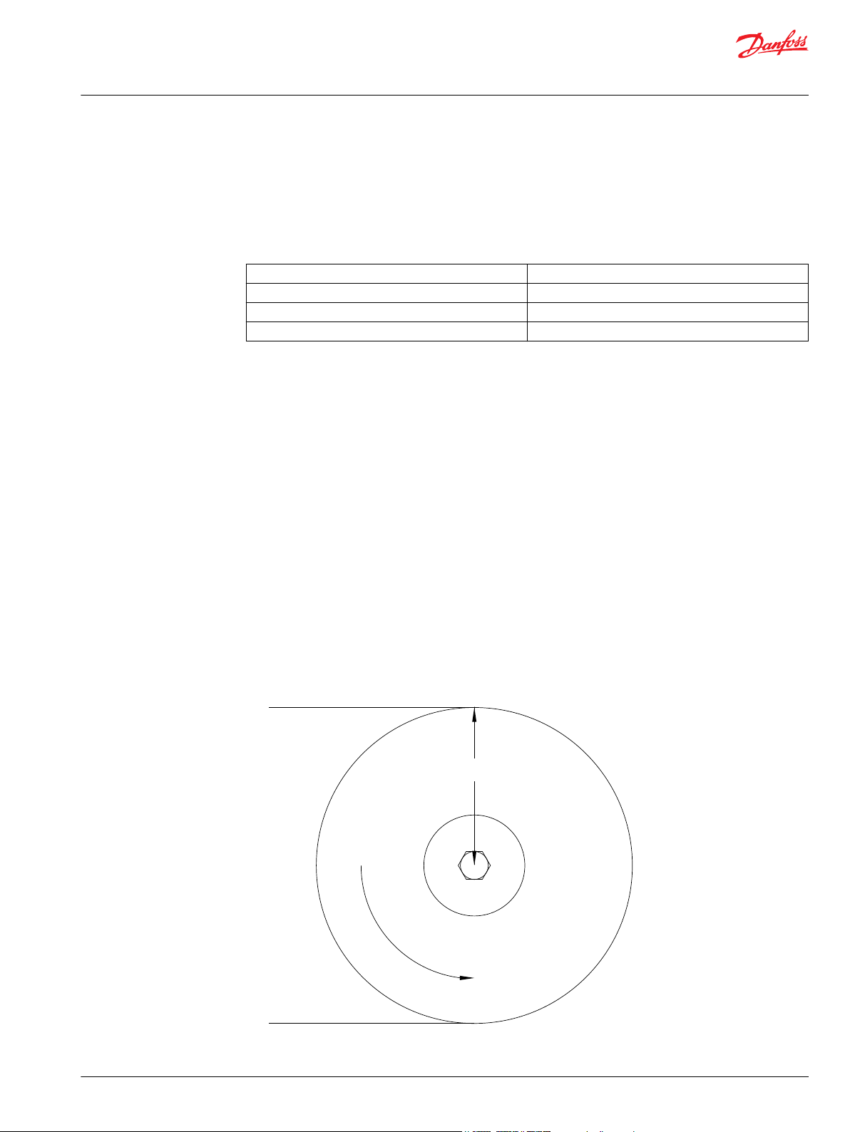
To determine the side load, the motor torque and pulley or sprocket radius must be known. Side load
may be calculated using the formula below. The distance from the pulley/sprocket centerline to the
mounting flange of the motor must also be determined. These two figures may then be compared to the
bearing and shaft load curve of the desired motor to determine if the side load falls within acceptable
load ranges.
Hydraulic Equations
Multiplication Factor Abbreviation Prefix
12
10
10
10
10
10
10
10
10
9
6
3
2
1
-1
-2
T tera
G giga
M mega
K kilo
h hecto
da deka
d deci
c centi
Theo. Speed (RPM) (1000 x LPM) / Displacement (cm3/rev)
(231 x GPM) / Displacement (in3/rev)
Theo. Torque (lb-in) (Bar x Disp. (cm3/rev)) / 20 pi
(PSI x Disp. (in3/rev) / 6.28
Power In (HP) (Bar x LPM) / 600
(PSI x GPM) / 1714
Power Out (HP) (Torque (Nm) x RPM) / 9543
10 | © Danfoss | June 2019 BC00000383en-000103
Page 11

Incorrect
Correct
P109323
Technical Information
Hydraulic Brakes
Technical Information
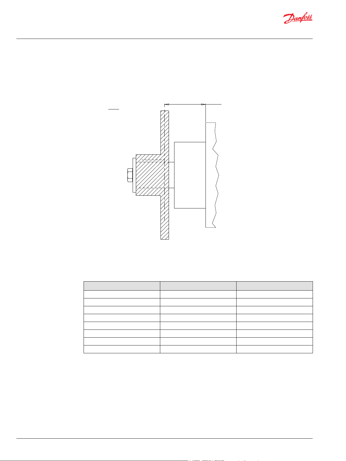
Shaft Nut Information
(Torque (lb-in) x RPM) / 63024
The tightening torques listed with each nut should only be used as a guideline. Hubs may require higher
or lower tightening torque depending on the material. Consult the hub manufacturer to obtain
recommended tightening torque. To maximize torque transfer from the shaft to the hub, and to
minimize the potential for shaft breakage, a hub with sufficient thickness must fully engage the taper
length of the shaft.
Hub engagement
©
Danfoss | June 2019 BC00000383en-000103 | 11
Page 12

A Slotted Nut
35MM TAPERED SHAFTS
B Lock Nut
B Lock Nut
B
Lock Nut
C
Solid Nut
C
Solid Nut
C Solid Nut
M24 x 1.5 Thread
A
Slotted Nut
1” TAPERED SHAFTS
3/4-28 Thread
A Slotted Nut
1-1/4” TAPERED SHAFTS
1-20 Thread
A Slotted Nut
1-3/8” & 1-1/2” TAPERED SHAFTS
1 1/8-18 Thread
33 [1.29]
5 [.19]
6 [.24]
12 [.48]
Torque Specifications: 20 - 23 daNm [150 - 170 ft.lb.]
29 [1.13]28 [1.12]
42 [1.64]
6 [.22]
6 [.24]
15 [.59]
Torque Specifications: 32.5 daNm [240 ft.lb.]
36 [1.42]
16 [.63]
3.5 [.14]
33 [1.29]
28 [1.11]
12 [.47]
33 [1.28]
23 [.92]
24 [.95]
28 [1.10]
Torque Specifications: 24 - 27 daNm [180 - 200 ft.lb.]
Torque Specifications: 20 - 23 daNm [150 - 170 ft.lb.]
44 [1.73]
5 [.19]
6 [.25]
14 [.55]
Torque Specifications: 38 daNm [280 ft.lb.] Max.
35 [1.38]38 [1.48]
16 [.63]
4 [.16]
40 [1.57]
38 [1.48]
14 [.55]
44 [1.73]
29 [1.14]
30 [1.18]
34 [1.34]
Torque Specifications: 33 - 42 daNm [240 - 310 ft.lb.] Torque Specifications: 38 daNm [280 ft.lb.] Max.
48 [1.90]
5 [.19]
6 [.22]
15 [.61]
Torque Specifications: 41 - 54 daNm [300 - 400 ft.lb.]
44 [1.73]42 [1.66]
16 [.63]
4 [.16]
51 [2.00]
42 [1.66]
15 [.61]
48 [1.90]
35 [1.38]
36 [1.42]
44 [1.73]
Torque Specifications: 34 - 48 daNm [250 - 350 ft.lb.]
Torque Specifications: 41 - 54 daNm [300 - 400 ft.lb.]
P109324
Technical Information
Hydraulic Brakes
Technical Information
12 | © Danfoss | June 2019 BC00000383en-000103
Page 13

P109449
Technical Information
Hydraulic Brakes
BK 913 and 915 Series
Overview
With safety an increasingly important factor in the design and manufacture of equipment, it has become
necessary to add a brake to many critical machine functions. In response to that concern, Danfoss offers
BK Series brakes. Based on technology proven in Danfoss integrated motor/brakes, this spring-applied,
hydraulically released brake provides up to 1500 Nm [13,300 lb-in] of holding torque for static brake
applications.
Other features contribute to the superior operation and durability of the BK brakes. All internal
components, including roller bearings, brake disks, springs and seals were chosen for maximum
durability. To further extend the life of the unit and reduce noise, all internal components run in an oil
bath. Two brake release ports are also provided to simplify plumbing and bleeding of the brake release
circuit during installation. All of these features combine to make BK Series brakes a top choice for any
static brake application requiring up to 1500 Nm [13,300 lb-in] of holding torque.
Features / Benefits
Heavy-duty roller bearings support high shaft loads and provide long life.
•
Dual release ports allow easier bleeding of brake release cavity.
•
Oil-filled cavity immerses all components providing quiet operation and reduced wear.
•
Typical Applications
Wheel drives, positioners, conveyors, door openers, swing drives, aerial work platforms and more
Specifications
913 Series Holding Torque 1130 Nm [10,000 lb-in]
915 Series Holding Torque 1500 Nm [13,300 lb-in]
Release Pressure 28 bar [400 psi]
Maximum Release Pressure 207 bar [3,000 psi]
Release Volume 11.5 cm3 [0.7 in3]
Max. Speed 250 rpm
Max. Operating Temperature 82 °C [180 °F]
Weight 16.8 kg [37 lb]
Fluid Type Mineral based oil
©
Danfoss | June 2019 BC00000383en-000103 | 13
Page 14

Ø 178 [7.00]
90°
50 [1.95]
25 [1.00]
Ø 200 [7.88]
7/16-20 Fill Hole
Port Plug Installed
(4) Ø 13 [.52]
13 [.50]
59 [2.34]
14.2 [.558]
11.3 [.443]
101.6 [3.999]
101.5 [3.997]
(2) SAE J51 4b
7/16-20 Release Ports,
Min. Depth 11 [.45]
913 Series - 107 [4.21]
915 Series - 117 [4.61]
4-HOLE, BRAKE MOUNT, ALIGNED PORTS
K30
7/16-20 UNF
P109450
Technical Information
Hydraulic Brakes
BK 913 and 915 Series
BK 913 and 915 Series Housings
Dimensions shown are without paint. Paint thickness can be up to 0.13 [.005].
4-Hole, Brake Mount, Aligned Ports
BK 913 and 915 Series Technical Information
Allowable Shaft Load / Bearing Curve
The bearing curve represents allowable bearing loads based on ISO 281 bearing capacity for an L10 life of
2,000 hours at 100 rpm. Radial loads for speeds other than 100 rpm may be calculated using the Bearing
Load Multiplication Factor Table on page 6.
14 | © Danfoss | June 2019 BC00000383en-000103
Page 15

3000
9000
913 SERIES BRAKE - SIDE LOAD CHART
7000
8000
6000
5000
4000
lb
2000
1000
1000
4000
3000
3500
2500
2000
1500
daN
500
8 in90 761 53
200 mm2251751500 25 12575
2 4
50 100
445 daN [1000 lb]
445 daN [1000 lb]
BEARING
SHAFT
P109451
3000
9000
915 SERIES BRAKE - SIDE LOAD CHART
7000
8000
6000
5000
4000
lb
2000
1000
1000
4000
3000
3500
2500
2000
1500
daN
500
8 in90 761 53
200 mm2251751500 25 12575
2 4
50 100
445 daN [1000 lb]
445 daN [1000 lb]
BEARING
SHAFT
P109452
Technical Information
Hydraulic Brakes
BK 913 and 915 Series
BK 913 Series Brake - Side Load Chart
BK 915 Series Brake - Side Load Chart
©
Danfoss | June 2019 BC00000383en-000103 | 15
Page 16

913 Series - 176 [6.92]
915 Series - 185 [7.29]
4 [.15]
8.0 [.314]
8.0 [.313]
45 [1.78]19 [.75]
Ø4 [.17]
5 [.20]
38.1 [1.499]
38.0 [1.498]
1:8 Taper
31.8 [1.250]
30.5 [1.200]
Max. Torque: 2700 Nm [19900 lb-in]
31
1-1/2” Tapered
A slotted hex nut is standard on this
shaft.
P109453
1 2 3 4 5 6 7 8
Standard
Black
No Paint
Standard
Solid Hex Nut
None
4-Hole, Brake Mount, Aligned Ports, 7/16-20 UNF
1-1/2” Tapered
4. SELECT A SHAFT OPTION
31
None
8. SELECT A MISCELLANEOUS OPTION
AA
000
1. CHOOSE SERIES DESIGNATION
2. SELECT A HOLDING TORQUE OPTION
3. SELECT A MOUNT & PORT OPTION
5. SELECT A PAINT OPTION
A
Z
6. SELECT A VALVE CAVITY / CARTRIDGE OPTION
7. SELECT AN ADD-ON OPTION
A
C
A
K30
Hydraulic Brake
Hydraulic Brake
913
915
P109454
Technical Information
Hydraulic Brakes
BK 913 and 915 Series
BK 913 and 915 Series Shafts
BK 913 and 915 Series Ordering Information
16 | © Danfoss | June 2019 BC00000383en-000103
Page 17

P109449
Technical Information
Hydraulic Brakes
AB 920 Series
Overview
The AB series is a multi-wet-disc-brake that provides superior performance; all internal components are
fully immersed in pre-filled fluid and are environmentally sealed to prevent contamination and corrosion
while providing brake durability and maintaining proper holding capacity. Compact design and large
holding torque along with a lower release pressure and lower free turn torque saves your space and
reduces cost. Two brake release ports provide simple plumbing and the bleeding of the brake release
circuit during installation.
Features / Benefits
Compact design.
•
Ball bearings support higher shaft loads and provide longer life shaft seal life.
•
Dual release ports allow easier bleeding of brake release cavity.
•
Oil-filled cavity immerses all components providing quiet operation.
•
Large holding torque with lower release pressure and free turn torque.
•
Typical Applications
Wheel drives, positioners, conveyors, door openers, swing drives, aerial work platforms and more
Specifications
Holding Torque 475 Nm [4,200 lb-in]
Release Pressure 20 bar [290 psi]
Maximum Release Pressure 207 bar [3,000 psi]
Release Volume 9.0 cm3 [0.55 in3]
Max. Speed 250 rpm
Max. Operating Temperature 82 °C [180 °F]
Weight 9.25 kg [20.4 lb]
Fluid Type Mineral based oil
AB 920 Series Housings
Dimensions shown are without paint. Paint thickness can be up to 0.13 [.005].
©
Danfoss | June 2019 BC00000383en-000103 | 17
Page 18

Ø149.35 [5.880]
Ø149.10 [5.870]
30°
30°
47 [1.85] Max.
Ø178 [6.99]
Ø82 [3.23]
Max.
Ø110 [4.33]
Max.
Ø95.28 [3.750]
Ø95.12 [3.746]
(2) 7/16-20 UNF Release Port,
Min. Depth 12 [.45]
(2) 1/8-28 Fill Port
82.41 [3.244]
81.39 [3.204]
30° 30°
30°
Ø13.7 [.539]
Ø13.5 [.532]
4-HOLE, BRAKE MOUNT
K30
7/16-20 UNF
P109456
1200
2800
920 SERIES BRAKE - SIDE LOAD CHART
2400
2000
1600
lb
800
400
400
1200
1000
800
600
daN
200
8 in90 761 53
200 mm2251751500 25 12575
2 4
50 100
111 daN [250 lb]
111 daN [250 lb]
BEARING
P109457
Technical Information
Hydraulic Brakes
AB 920 Series
4-Hole, Brake Mount
AB 920 Series Technical Information
Allowable Shaft Load / Bearing Curve
The bearing curve represents allowable bearing loads based on ISO 281 bearing capacity for an L10 life of
2,000 hours at 100 rpm. Radial loads for speeds other than 100 rpm may be calculated using the Bearing
Load Multiplication Factor Table on page 6.
AB 920 Series Brake - Side Load Chart
18 | © Danfoss | June 2019 BC00000383en-000103
Page 19

3/4-16 UNF Slotted Hex Nut
6.35 [.250]
6.30 [.248]
2.65 [.108]
2.63 [.100]
Ø25.425 [1.001]
Ø25.375 [.999]
90.47 [3.562]
87.43 [3.442]
Ø3.96 [.156]
35.18 [1.384]
34.68 [1.366]
35.15 [1.383]
34.65 [1.365]
19 [.75]
4.7 [.185]
19 [.75]
4.7 [.185]
31.75 [1.250]
31.70 [1.248]
Taper 1:8
31.70 [1.248]
31.38 [1.235]
88.64 [3.489]
85.59 [3.369]
31.70 [1.248]
31.38 [1.235]
7.95 [.313]
7.93 [.312]
3.30 [.130]
3.09 [.121]
1-20 UNEF Slotted Hex Nut
Ø4.42 [.174]
Taper 1:8
13 1” Tapered 22 1-1/4” Tapered
P109458
1 2 3 4 5 6 7 8
475 Nm [4200 lb-in]
Black
Black, Unpainted Mounting Surface
Standard
None
4-Hole, Brake Mount, 7/16-20 UNF
1” Tapered
1-1/4” Tapered
4. SELECT A SHAFT OPTION
13
22
1.50 [.060] Pilot Height (Standard)
3.18 [.125] Pilot Height
6.35 [.250] Pilot Height
Single Throttle Valve With Standard Pilot Height
Two Throttle Valves With Standard Pilot Height
8. SELECT A MISCELLANEOUS OPTION
AA
AY
AZ
TC
TD
000
1. CHOOSE SERIES DESIGNATION
2. SELECT A HOLDING TORQUE OPTION
3. SELECT A MOUNT & PORT OPTION
5. SELECT A PAINT OPTION
A
B
6. SELECT A VALVE CAVITY / CARTRIDGE OPTION
7. SELECT AN ADD-ON OPTION
A
A
K30
Hydraulic Brake
920
P109459
Technical Information
Hydraulic Brakes
AB 920 Series
AB 920 Series Shafts
AB 920 Series Ordering Information
©
Danfoss | June 2019 BC00000383en-000103 | 19
Page 20

P109460
Technical Information
Hydraulic Brakes
FB 925 Series
Overview
The FB series is a multi-wet-disc-brake that provides superior performance; all internal components are
fully im- mersed in pre-filled fluid and are environmentally sealed to prevent contamination and
corrosion while providing brake durability and maintaining proper holding capacity. Compact design and
large holding torque along with a lower release pressure and lower free turn torque saves your space and
reduces cost.
Features / Benefits
Compact design.
•
Heavy-duty roller bearings support higher shaft loads and provide longer life shaft seal life.
•
Oil-filled cavity immerses all components providing quiet operation.
•
Large holding torque with lower release pressure and free turn torque.
•
Typical Applications
Wheel drives, positioners, conveyors, door openers, swing drives, aerial work platforms and more
Specifications
Release Pressure 20 bar [290 psi]
Maximum Release Pressure 207 bar [3,000 psi]
Release Volume 9.0 cm3 [0.55 in3]
Max. Speed 250 rpm
Max. Operating Temperature 82 °C [180 °F]
Weight 10.9 kg [24 lb]
Fluid Type Mineral based oil
FB 925 Series Housings
Dimensions shown are without paint. Paint thickness can be up to 0.13 [.005].
20 | © Danfoss | June 2019 BC00000383en-000103
Page 21

Ø159 [6.26]
10.4 [.409]
8.6 [.339]
Ø186 [7.32] Max.
Ø110 [4.33]
Max.
47 [1.85] Max.
Ø114.25 [4.498]
Ø114.20 [4.496]
1/8-28 Fill Port
85.1 [3.350]
84.7 [3.334]
15°
45°
Ø13.8 [.540]
Ø13.2 [.520]
7/16-20 UNF Release Port,
Min. Depth 11.5 [.45]
87.3 [3.44]
86.7 [3.42]
4-HOLE, BRAKE MOUNT
K30
7/16-20 UNF
P109461
925 SERIES BRAKE - SIDE LOAD CHART
lb daN
8 in90 761 53
200 mm2251751500 25 12575
2 4
50 100
5000
9000
8000
7000
6000
3000
4000
2000
1000
1000
4000
3500
2500
3000
2000
1500
500
111 daN [250 lb]
111 daN [250 lb]
BEARING
P109462
Technical Information
Hydraulic Brakes
FB 925 Series
4-Hole, Brake Mount
FB 925 Series Technical Information
Allowable Shaft Load / Bearing Curve
The bearing curve represents allowable bearing loads based on ISO 281 bearing capacity for an L10 life of
2,000 hours at 100 rpm. Radial loads for speeds other than 100 rpm may be calculated using the Bearing
Load Multiplication Factor Table on page 6.
FB 925 Series Brake - Side Load Chart
©
Danfoss | June 2019 BC00000383en-000103 | 21
Page 22

7.95 [.313]
7.93 [.312]
3.30 [.130]
3.09 [.122]
Ø38.10 [1.500]
Ø38.05 [1.498]
150.50 [5.925]
148.78 [5.857]
Ø4.4 [.173]
42.25 [1.663]
41.75 [1.644]
36.25 [1.427]
35.75 [1.408]
5.5 [.217]
21 [.83]
5.5 [.217]
32.00 [1.260]
31.95 [1.258]
Taper 1:8
31.70 [1.248]
31.38 [1.235]
144.50 [5.689]
142.75 [5.621]
31.70 [1.248]
31.38 [1.235]
7.95 [.313]
7.93 [.312]
3.30 [.130]
3.09 [.122]
1-20 UNEF Slotted Hex Nut
Ø4.4 [.173]
Taper 1:8
21 [.83]
1-1/8-18 UNEF Slotted Hex Nut
31 1-1/2” Tapered D7 32mm Tapered
P109463
1 2 3 4 5 6 7 8
350 Nm [3100 lb-in]
550 Nm [4900 lb-in]
650 Nm [5750 lb-in]
Black
Black, Unpainted Mounting Surface
Standard
None
4-Hole, Brake Mount, 7/16-20 UNF
1-1/2” Tapered
32mm Tapered
4. SELECT A SHAFT OPTION
31
D7
None
8. SELECT A MISCELLANEOUS OPTION
AA
350
550
650
1. CHOOSE SERIES DESIGNATION
2. SELECT A HOLDING TORQUE OPTION
3. SELECT A MOUNT & PORT OPTION
5. SELECT A PAINT OPTION
A
B
6. SELECT A VALVE CAVITY / CARTRIDGE OPTION
7. SELECT AN ADD-ON OPTION
A
A
K30
Hydraulic Brake
925
P109464
Technical Information
Hydraulic Brakes
FB 925 Series
FB 925 Series Shafts
FB 925 Series Ordering Information
22 | © Danfoss | June 2019 BC00000383en-000103
Page 23

P109465
Technical Information
Hydraulic Brakes
SB 930 Series
Overview
The SB Series is a multiple-wet-disc-brake that provides superior performance in an extremely compact
package. Unlike conventional brakes offered today, the SB brake is performance-matched to fit the full
range of small-frame SAE A mount motors available today. With an overall diameter of less than 137mm
[5.4 in] the SB has a holding capacity in excess of 620 Nm [5,500 lb-in] and is easily mated to a variety of
global industry standard motor mounting and shaft options. In addition, the SB Series can be used as a
stand-alone brake solution without an input drive motor. This option further opens design flexibility to
meet a wider variety of application needs.
Features / Benefits
All wear components are fully immersed in fluid (wet multi-disc design)
•
Performance-matched to fit small-frame motors with SAE A mounts
•
Release pressure independent of motor pressure
•
Brake directly coupled to the output shaft
•
Wide-variety of input and output shaft options
•
Environmentally sealed / factory prefilled with oil
•
Proven, Quiet, Trouble-Free Operation
•
Compact, Cost-Effective Package
•
Simplifies System Circuits - Eliminates Need for Pressure- Reducing Valve
•
Series Operating Capability
•
Reliable Performance - Fewer Critical Components
•
Design Flexibility
•
Global Interchangeability
•
Suited for “Stand Alone” Brake Applications
•
Ease of Installation
•
Typical Applications
Wheel drives, positioners, conveyors, door openers, swing drives, aerial work platforms and more
©
Danfoss | June 2019 BC00000383en-000103 | 23
Page 24

Cast Dimensions are ± 0.8 mm [.030 in.] *Fill and drain ports for filling and draining the brake only.
No system connections are to be made to the fill and drain ports. These ports are not suitable for use in a cooling loop.
13.7 [.54]
71.8 [2.83]
95.3 [3.75]
17°
106.4 [4.19]
Brake Release Port
130.8 [5.15]
129.3 [5.09]
82.6 [3.250]
82.5 [3.248]
6 [.24]
115.1 [4.53] Max.
82.7 [3.255]
82.6 [3.253]
130.8 [5.15]
129.3 [5.09]
(2) M12 x 1.75
Mounting Holes
(2) M12 x 1.75
Mounting Holes
22.6 [.89]
9.5 [.374]
*(4) Fill and Drain Ports
A10 - 42.3 [1.67]
A11 - 41.6 [1.64]
13.7 [.54]
71.8 [2.83]
130.1 [5.12]
17°
106.4 [4.19]
Brake Release Port
82.6 [3.250]
82.5 [3.248]
6 [.24]
115.1 [4.53] Max.
82.7 [3.255]
82.6 [3.253]
130.8 [5.15]
129.3 [5.09]
22.6 [.89]
9.5 [.374]
*(4) Fill and Drain Ports
A30 - 42.3 [1.67]
A31 - 41.6 [1.64]
A11 G 1/4
2-HOLE, SAE A BRAKE MOUNT
A10
7/16-20 UNF
A31
G 1/4
A30
7/16-20 UNF
4-HOLE, SAE A BRAKE MOUNT
P109466
Technical Information
Hydraulic Brakes
SB 930 Series
SB 930 Series Housings
Specifications
Code 225 315 415 520 620
Holding Torque 225 Nm [2,000 lb-
in]
Max. Release
Pressure
Full Release
207 bar [3,000
psi]
23 bar [330 psi] 23 bar [330 psi] 23 bar [330 psi] 36 bar [520 psi] 36 bar [520 psi]
315 Nm [2,800 lbin]
207 bar [3,000
psi]
415 Nm [3,700 lbin]
207 bar [3,000
psi]
520 Nm [4,600 lbin]
207 bar [3,000
psi]
620 Nm [5,500 lbin]
207 bar [3,000
psi]
Pressure
Release Volume 8.3 cm3 [.51 in3] 8.3 cm3 [.51 in3] 8.3 cm3 [.51 in3] 8.3 cm3 [.51 in3] 8.3 cm3 [.51 in3]
Max. Speed 250 rpm 250 rpm 250 rpm 250 rpm 250 rpm
Unit Weight 8 kg [17.6 lb] 8 kg [17.6 lb] 8 kg [17.6 lb] 8 kg [17.6 lb] 8 kg [17.6 lb]
Dimensions shown are without paint. Paint thickness can be up to 0.13 [.005].
24 | © Danfoss | June 2019 BC00000383en-000103
Page 25

12 [.46]
32.6 [1.285]
31.4 [1.235]
10.0 [.394]
9.9 [.392]
25.4 [.999]
25.4 [.998]
20 [.78] Min.
5/16-18 UNC,
Min. Depth 18 [.70]
34.8 [1.372]
34.5 [1.359]
Ø32.0 [1.260]
Ø31.9 [1.259]
Ø25.3 [.996]
Ø25.2 [.992]
43 [1.68]
52 [2.03]
52 [2.03]
43 [1.68]
67 [2.62]
M8 x 1.25, Min. Depth 18 [.70]
56 [2.22]
6B Spline
SAE J499 Standard
6.4 [.251]
6.4 [.250]
28.2 [1.110]
28.0 [1.101]
5 [.18]
25.9 [1.02]
24.6 [.970]
5/16-18 UNC,
Min. Depth 18 [.70]
5 [.21]
30.9 [1.218]
29.7 [1.168]
8.0 [.315]
8.0 [.313]
28.0 [1.102]
27.7 [1.091]
Ø25.0 [.984]
Ø25.0 [.983]
52 [2.03]
M8 x 1.25, Min. Depth 18 [.70]
43 [1.68]
58.6 [2.3]
6.3 [2.5]
Ø 25.4 [1.00]
58.6 [2.3]
28.4 [1.12]
Ø 25.1 [.99]
8.1 [.319]
26.6 [1.047]
10.1 [.398]
Mounting
Surface
26.6 [1.047]
10.1 [.398]
Mounting
Surface
Ø29.9 [1.177]
Ø29.9 [1.177]
ZZ 6B Spline, 6B Input
ZW
1” Straight, 6B Input
ZX
32mm Straight, 25mm Input
ZU
32mm Straight, 6B Input
ZY 25mm Straight, 25mm Input ZT 25mm Straight, 6B Input
6B INPUT DIMENSIONS 25MM INPUT DIMENSIONS
P109468
Technical Information
Hydraulic Brakes
SB 930 Series
SB 930 Series Shafts
Cast Dimensions are ± 0.8 mm [.030 in.] *Fill and drain ports for filling and draining the brake only.
No system connections are to be made to the fill and drain ports. These ports are not suitable for use in a
cooling loop.
©
Danfoss | June 2019 BC00000383en-000103 | 25
Page 26

3000
8000
930 SERIES BRAKE - SIDE LOAD CHART
7000
6000
5000
4000
lb
2000
1000
1000
3500
3000
2500
2000
1500
daN
500
2 in3-4 10-3 -1-2
50 mm75-100 250-75 -25-50
145 daN [320 lb]
145 daN [320 lb]
BEARING
P109467
Technical Information
Hydraulic Brakes
SB 930 Series
SB 930 Series Technical Information
Allowable Shaft Load / Bearing Curve
The bearing curve represents allowable bearing loads based on ISO 281 bearing capacity for an L10 life of
2,000 hours at 100 rpm. Radial loads for speeds other than 100 rpm may be calculated using the Bearing
Load Multiplication Factor Table on page 6.
SB 930 Series Brake - Side Load Chart
SB 930 Series Installation Information
The SB Brake is a wet multi-disc type static brake and is shipped factory filled with fluid. The fluid used is a
standard SAE 20 hydraulic fluid. A hydraulic motor can be mounted to the SB Brake to provide a complete
motor/brake package. A shipping cover protects and seals the input interface until it is ready for
installation. The shipping cover is removed by removing the two cap screws and following the motor
installation procedure below. Mounting pilot surfaces need to be free of paint or other substances for
proper assembly and leak-free performance. Standard SB brakes are sold unpainted with an easy to
remove shipping cover. Stand-alone SB brakes come standard painted and factory installed cover.
The input interface must be sealed to keep the brake environmentally protected and bearings fully
26 | © Danfoss | June 2019 BC00000383en-000103
immersed in fluid for proper lubrication and long life. Standard SAE 20 hydraulic oil is used in the brake
cavity as well as typically used in hydraulic systems.
An internal seal is provided to seal long-pilot motors. When a short-pilot motor is used, an o-ring face seal
is needed to properly seal the motor/brake interface. Two mounting bolts (M12 x 1.75 thread) and an oring seal with mounting instructions are included in the brake installation kit 930999001 and shipped
with each SB Brake.
Page 27

2.3 [.090]
2.1 [.084]
2.54 [.100]
Face Seal
Factory Installed
Pilot Seal
To remove cover, pierce and
pry with a sharp awl.
When using the 930 Series as a
Stand-Alone unit, this cover is
not to be removed. It retains oil
needed to lubricate the bearings.
930 SERIES BRAKE INSTALLATION
The factory installed pilot seal may be left in place. However, this seal will not provide proper sealing for motors with
short pilot mounts, therefore, the face seal contained in the mounting kit must be used.
P109470
1 2 3 4 5 6 7 8
225 Nm [2000 lb-in]
315 Nm [2800 lb-in]
415 Nm [3700 lb-in]
Hydraulic Brake
520 Nm [4600 lb-in]
620 Nm [5500 lb-in]
2-Hole, SAE A Brake Mount, 7/16-20 UNF
2-Hole, SAE A Brake Mount, G 1/4
4-Hole, SAE A Brake Mount, 7/16-20 UNF
4-Hole, SAE A Brake Mount, G 1/4
25mm Straight, 6B Input
32mm Straight, 6B Input
1” Straight, 6B Input
Black
Black, Unpainted Mounting Surface
No Paint
Standard
Standard
None
32mm Straight, 25mm Input
25mm Straight, 25mm Input
6B Spline, 6B Input
P109469
930
1. CHOOSE SERIES DESIGNATION
2. SELECT A HOLDING TORQUE
225
315
415
520
620
3. SELECT A MOUNT & PORT OPTION
A10
A11
A30
A31
4. SELECT A SHAFT OPTION
ZT
ZU
ZW
ZX
ZY
ZZ
5. SELECT A PAINT OPTION
A
B
Z
6. SELECT A VALVE CAVITY / CARTRIDGE OPTION
7. SELECT AN ADD-ON OPTION
A
8. SELECT A MISCELLANEOUS OPTION
AA
A
Technical Information
Hydraulic Brakes
SB 930 Series
930 Series Brake Installation
SB 930 Series Ordering Information
The factory installed pilot seal may be left in place. However, this seal will not provide proper sealing for
motors with short pilot mounts, therefore, the face seal contained in the mounting kit must be used.
©
Danfoss | June 2019 BC00000383en-000103 | 27
Page 28
B1
RIGHT BRAKE
LEFT BRAKE
P109471
Technical Information
Hydraulic Brakes
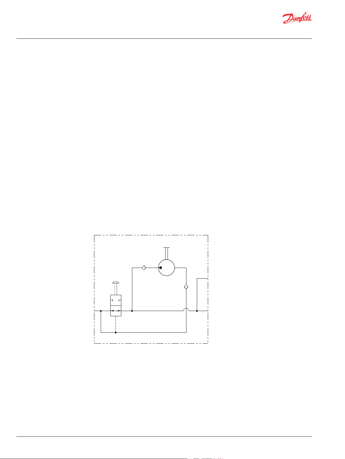
RP 960 Series
Overview
The 960 Series is a device designed to replace existing, costly and complicated hydraulic brake release
hand pumps that are present on various types of mobile equipment. It is typically used to release various
types of spring applied/ hydraulically released brakes. Depending on the brake, typically 1-5 pumps of
the 960 will release the brake. This enables equipment to be moved to a service area or a recharge/refuel
station.
To operate, the equipment operator must depress the valve rod until it is firmly seated. The operator
must then pump the pump rod until the brakes are released. If the hydraulic circuit is pressurized at any
time during or after the 960 has released the brakes, the valve rod will automatically pop out and the
mobile equipment will revert to its normal operation. This serves as a built in safety feature that ensures
the equipment’s normal braking operation is never accidentally disabled.
The 960 is a simplified product compared to competitive brands that are currently available. In addition,
the product is a cost competitve alterative that offers superior performance and design flexibility.
Specifications
Typical output flow 1cm3 [.06 in3] - 2cm3 [.12 in3] per stroke depending upon oil viscosity, speed of
•
stroke, and pressure.
Maximum working pressure of 276 bar [4000 psi].
•
Schematic
28 | © Danfoss | June 2019 BC00000383en-000103
Page 29

45 [1.78]
26 [1.04]
Stroke
35 [1.38]
76 [3.00]
(2) 3/8-16 UNC
Through Mounting Holes
28 [1.10]
24 [.95]
99 [3.90]
25 [1.00]
22 [.85]
Pump Rod
Valve Rod
9 [.36]
9 [.27]
9 [.38]
14 [.55]
41 [1.62]
ORDER CODES 960020A10AAAA 960020A12AAAA960020A11AAAA
The 960020A10AAAA has 7/16-20 UNF Ports. The 960020A11AAAA has #4 JIC fittings pre-installed. The 960020A12AAAA has G 1/4 Ports.
P109472
Technical Information
Hydraulic Brakes
RP 960 Series
RP 960 Series Ordering Information
©
Danfoss | June 2019 BC00000383en-000103 | 29
Page 30

Technical Information
Hydraulic Brakes
30 | © Danfoss | June 2019 BC00000383en-000103
Page 31

Technical Information
Hydraulic Brakes
©
Danfoss | June 2019 BC00000383en-000103 | 31
Page 32

Technical Information
Hydraulic Brakes
32 | © Danfoss | June 2019 BC00000383en-000103
Page 33

Danfoss
Power Solutions GmbH & Co. OHG
Krokamp 35
D-24539 Neumünster, Germany
Phone: +49 4321 871 0
Danfoss
Power Solutions ApS
Nordborgvej 81
DK-6430 Nordborg, Denmark
Phone: +45 7488 2222
Danfoss
Power Solutions (US) Company
2800 East 13th Street
Ames, IA 50010, USA
Phone: +1 515 239 6000
Danfoss
Power Solutions Trading
(Shanghai) Co., Ltd.
Building #22, No. 1000 Jin Hai Rd
Jin Qiao, Pudong New District
Shanghai, China 201206
Phone: +86 21 3418 5200
Products we offer:
Hydro-Gear
www.hydro-gear.com
Daikin-Sauer-Danfoss
www.daikin-sauer-danfoss.com
DCV directional control
•
valves
Electric converters
•
Electric machines
•
Electric motors
•
Hydrostatic motors
•
Hydrostatic pumps
•
Orbital motors
•
PLUS+1® controllers
•
PLUS+1® displays
•
PLUS+1® joysticks and
•
pedals
PLUS+1® operator
•
interfaces
PLUS+1® sensors
•
PLUS+1® software
•
PLUS+1® software services,
•
support and training
Position controls and
•
sensors
PVG proportional valves
•
Steering components and
•
systems
Telematics
•
Danfoss Power Solutions is a global manufacturer and supplier of high-quality hydraulic and
electric components. We specialize in providing state-of-the-art technology and solutions
that excel in the harsh operating conditions of the mobile off-highway market as well as the
marine sector. Building on our extensive applications expertise, we work closely with you to
ensure exceptional performance for a broad range of applications. We help you and other
customers around the world speed up system development, reduce costs and bring vehicles
and vessels to market faster.
Danfoss Power Solutions – your strongest partner in mobile hydraulics and mobile
electrification.
Go to www.danfoss.com for further product information.
We offer you expert worldwide support for ensuring the best possible solutions for
outstanding performance. And with an extensive network of Global Service Partners, we also
provide you with comprehensive global service for all of our components.
Local address:
Danfoss can accept no responsibility for possible errors in catalogues, brochures and other printed material. Danfoss reserves the right to alter its products without notice. This also applies to products
already on order provided that such alterations can be made without subsequent changes being necessary in specifications already agreed.
All trademarks in this material are property of the respective companies. Danfoss and the Danfoss logotype are trademarks of Danfoss A/S. All rights reserved.
©
Danfoss | June 2019 BC00000383en-000103
 Loading...