

Page 1
Installation Instructions
Remote Mounting of LCP
®
VLT
Items Supplied
•
•
•
•
•
•
Length [m (ft)] Ordering number
3 (10) 134B5223
5 (16) 134B5224
10 (33) 134B5225
HVAC Drive FC 102
LCP cables with 2 M12 connectors (90° male connector and straight female connector). Cable lengths: 3 m, 5 m, and 10 m
(10 ft, 16 ft, 33 ft). See also Tab le 1.1.
Blind cover with M12 female connector.
Base plate with D-sub connector and M12 male connector.
Two gaskets and 1 nut for the D-sub connector.
Intermediate cover with the front cover.
Disassembly tool.
Table 1.1 Cable Ordering Numbers
More Items Required
Local control panel (LCP).
•
Four M4 self-tapping screws for mounting.
•
NOTICE
This instruction is valid for frequency converters that were ordered with the LCP. Front covers of frequency converters that
were ordered without LCPs do not have holes for mounting the blind covers.
Safety Instructions
For important information about safety precautions for installation, refer to the product-specic operating guide.
WARNING
DISCHARGE TIME
The frequency converter contains DC-link capacitors, which can remain charged even when the frequency converter is not
powered. High voltage can be present even when the warning LED indicator lights are o. Failure to wait the specied time
after power has been removed before performing service or repair work can result in death or serious injury.
Stop the motor.
•
Disconnect AC mains and remote DC-link power supplies, including battery back-ups, UPS, and DC-link connections to
•
other frequency converters.
Disconnect or lock PM motor.
•
Wait for the capacitors to discharge fully. The minimum duration of waiting time is specied in .
•
Before performing any service or repair work, use an appropriate voltage measuring device to make sure that the
•
capacitors are fully discharged.
Danfoss A/S © 11/2017 All rights reserved. MI05A202
Page 2
Installation Instructions
Voltage [V] Minimum waiting time (minutes)
4 7 15 20 30 40
200–240 1.1–3.7 kW
(1.50–5 hp)
380–480 1.1–7.5 kW
(1.50–10 hp)
400 – – – 90–315 kW
500 – – – 110–355 kW
525 – – – 75–315 kW
525–600 1.1–7.5 kW
(1.50–10 hp)
690 – – – 90–315 kW
525–690 – 1.1–7.5 kW
(1.50–10 hp)
Remote Mounting of LCP
®
HVAC Drive FC 102
VLT
–5.5–45 kW
(7.5–60 hp)
– 11–90 kW
(15–121 hp)
(121–450 hp)
(150–500 hp)
(100–450 hp)
– 11–90 kW
(15–121 hp)
(100– 350 hp)
11–90 kW
(15–121 hp)
–––
– – 315–1000 kW
–––
–400–1400 kW
(450–1350 hp)
––
––
––
––
–
(500–1550 hp)
450–1400 kW
(600–1550 hp)
Table 1.2 Discharge Time, VLT® HVAC Drive FC 102
Mechanical Installation
NOTICE
The guidelines in this instruction are applicable for a
frequency converter in a standard conguration without any
modications.
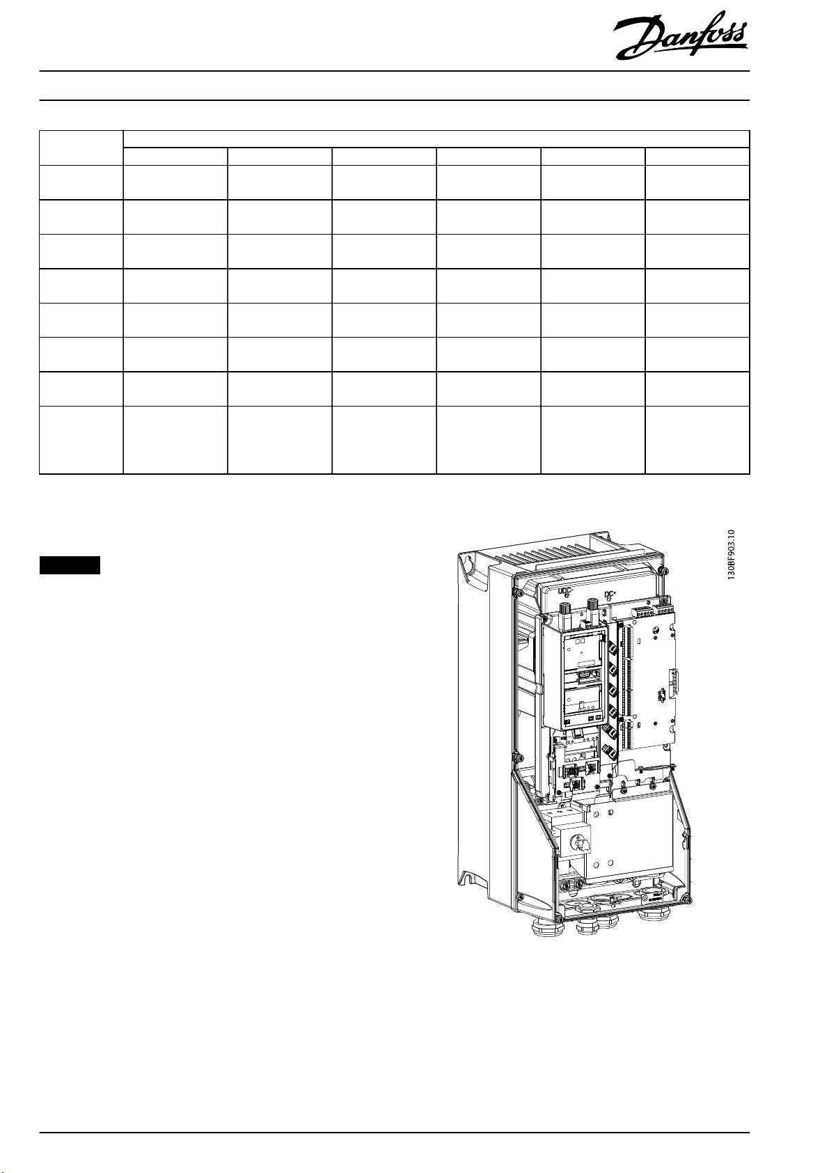
Installing the blind cover
1. Remove the front cover from the frequency converter
and then remove the LCP, see Illustration 1.1.
Illustration 1.1 Frequency Converter with the LCP Removed
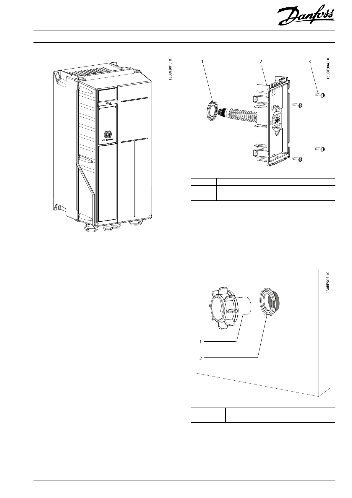
2. Install the blind cover with the gasket and the M12
connector.
3. Install the front cover on the frequency converter, see
Illustration 1.2.
2
Danfoss A/S © 11/2017 All rights reserved. MI05A202
Page 3
Installation Instructions
Remote Mounting of LCP
®
HVAC Drive FC 102
VLT
1Gasket
2 Base plate
3Screws
Illustration 1.2 Frequency Converter with the Blind Cover
Mounting the remote LCP
1. Drill the hole in the wall that holds the LCP. The hole
diameter: 24 mm ±1 mm (1 in ±0.04 in). To ensure
that the base plate adjoins the wall, drill the hole
perpendicular to the wall (±1°). The kit is suitable for
insulated walls 30–90 mm (1.2–3.5 in) thick and solid
walls 1–20 mm (0.04–0.8 in) thick.
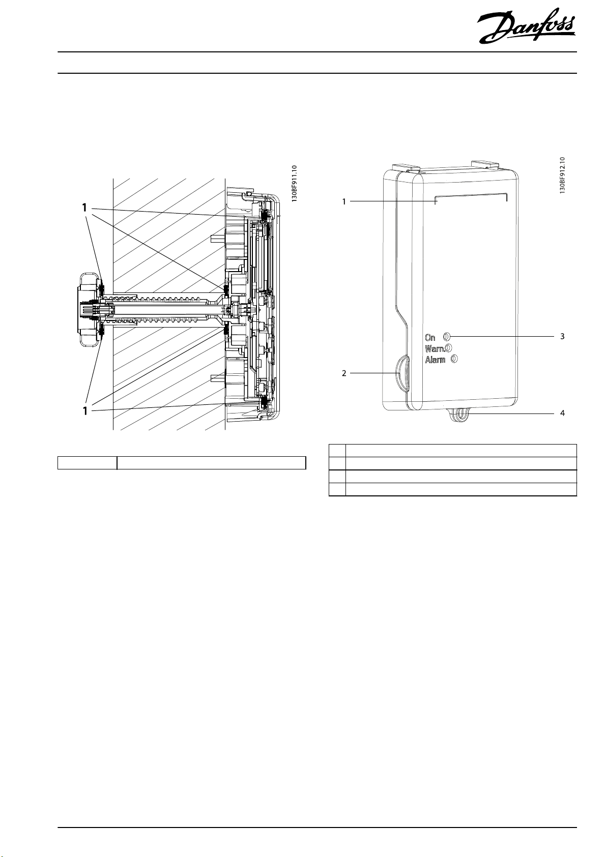
2. Install the base plate with the D-sub connector. Use
the gasket and 4 self-tapping screws to secure the
plate. See Illustration 1.3.
Illustration 1.3 Base Plate with D-sub Connector
3. Put the nut on the D-sub connector and tighten it
with torque of 1.5 Nm (13 in-lb). Ensure that the base
plate and the nut are tight on both sides of the wall.
For very thin walls, the nut can also be turned 180°.
See Illustration 1.4 and Illustration 1.5.
1Nut
2Gasket
Illustration 1.4 The Nut, Standard Position, for Thick/Insulated
Wall s
MI05A202 Danfoss A/S © 11/2017 All rights reserved.
3
Page 4
Installation Instructions
Illustration 1.5 The Nut, Turned 180°, for Thin Walls
Remote Mounting of LCP
VLT
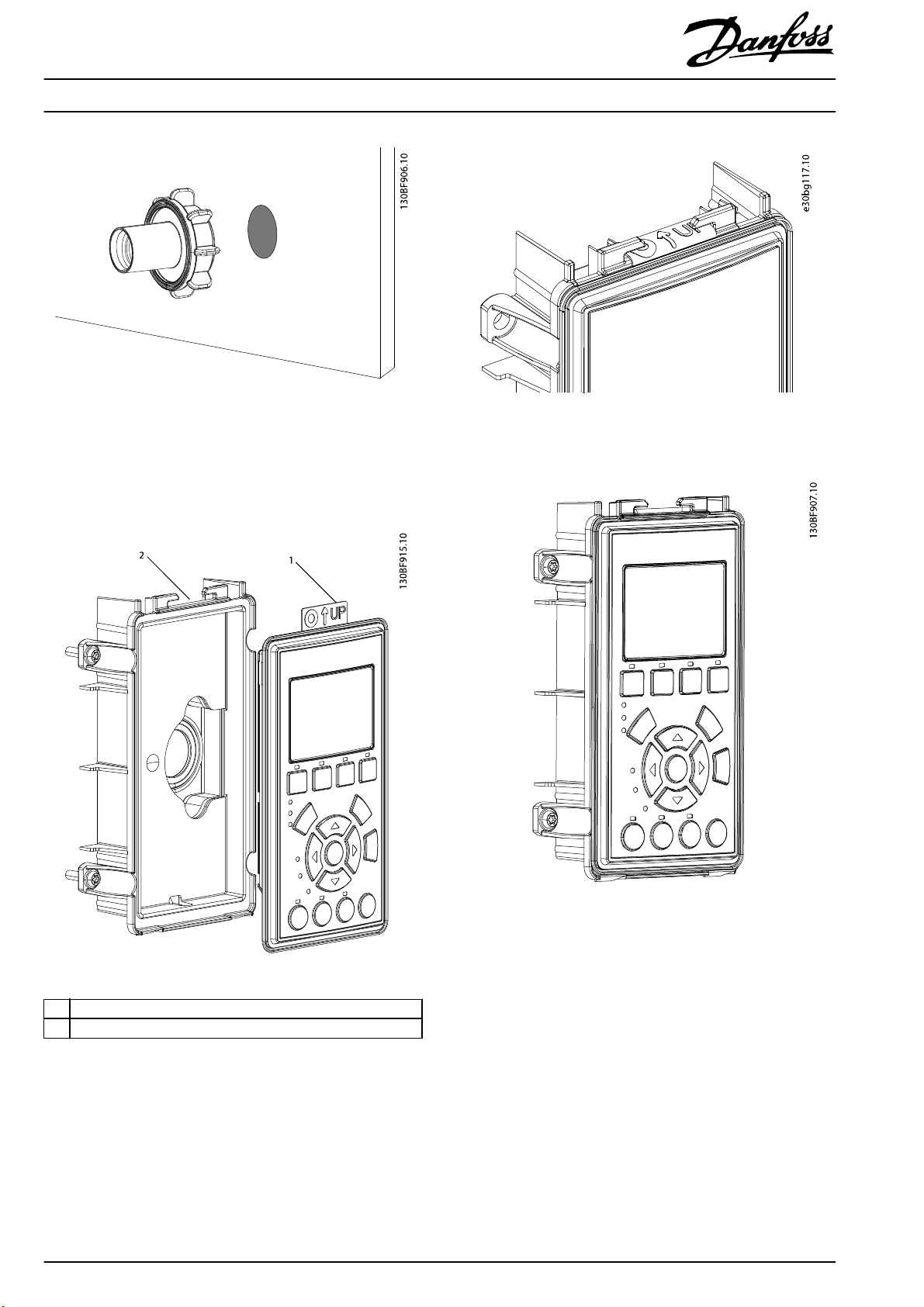
4. Mount the LCP with the gasket on the base plate.
Insert the rubber ap in the opening at the top of
the cradle, see Illustration 1.6 and Illustration 1.7.
Illustration 1.8 shows the base plate with the LCP.
®
HVAC Drive FC 102
Illustration 1.7 Rubber Flap in the Opening
1 Rubber ap
2 Opening at the top of the cradle
Illustration 1.6 Insert the Rubber Flap into the Opening
4
Danfoss A/S © 11/2017 All rights reserved. MI05A202
Illustration 1.8 Base Plate with LCP
Page 5

Installation Instructions
Remote Mounting of LCP
®
VLT
5. Mount the intermediate cover and lid on the base
plate. The cover has a click-on type connection.
Connect the top of the lid to the cradle and then
push it until it clicks. The unit with this cover has
rating IP54. See Illustration 1.9, and Illustration 1.10.
HVAC Drive FC 102
Illustration 1.9 Connect the Lid with the Front Cover
Illustration 1.10 Base Plate with the Covers
MI05A202 Danfoss A/S © 11/2017 All rights reserved.
5
Page 6
Installation Instructions
Remote Mounting of LCP
®
HVAC Drive FC 102
VLT
Electrical Installation
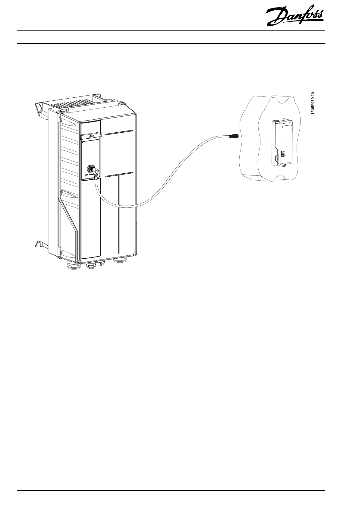
Connect the M12 connectors on the blind cover and the LCP with the supplied cable. See Illustration 1.11.
Illustration 1.11 Remote Connection of the LCP
6
Danfoss A/S © 11/2017 All rights reserved. MI05A202
Page 7
Installation Instructions
Remote Mounting of LCP
®
HVAC Drive FC 102
VLT
Areas with Gaskets on the Remote Unit
To make the remote unit more secure, the following areas are
tightened with gaskets:
Using the Remote LCP
The cover on the remote LCP has the following features:
1Gasket
Illustration 1.12 Remote Unit with Gaskets
1 Place for a label
2 Groove for opening the cover
3 Openings for the indicator lights
4 Rings for locking the cover
Illustration 1.13 Remote LCP with the Cover
The On, Warn., and Alarm indicator lights are visible
•
with the closed front cover. Lights are visible at an
angle up to 45°.
Lock the front cover using the rings at the bottom of
•
the cover. See Illustration 1.15.
Open the front cover using the groove at the side of
•
the cover. See Illustration 1.14.
The cover has a place for a label.
•
MI05A202 Danfoss A/S © 11/2017 All rights reserved.
7
Page 8

Installation Instructions
Remote Mounting of LCP
®
HVAC Drive FC 102
VLT
1 Disassembly tool
2 Holes for the disassembly tool
Illustration 1.14 Front Cover and Disassembly Tool
Illustration 1.15 Front Cover with Padlock
8
Danfoss A/S © 11/2017 All rights reserved. MI05A202
Page 9

Installation Instructions
Remote Mounting of LCP
®
HVAC Drive FC 102
VLT
Drilling Template
Place the drilling template against the wall to mark the hole locations. The scale of the template is 1:1.
Illustration 1.16 Drilling Template, Scale of 1:1
MI05A202 Danfoss A/S © 11/2017 All rights reserved.
9
Page 10

Danfoss can accept no responsibility for possible errors in catalogues, brochures and other printed material. Danfoss reserves the right to alter its products without notice. This also applies to products already on
order provided that such alterations can be made without subsequential changes being necessary in specifications already agreed. All trademarks in this mate rial are property of the respective companies. Danfoss
and the Danfoss logotype are trademarks of Danfoss A/S. All rights reserved.
Danfoss A/S
Ulsnaes 1
DK-6300 Graasten
vlt-drives.danfoss.com
MI05A202130R0796 11/2017
*MI05A202*
 Loading...