

Page 1
Datasheet
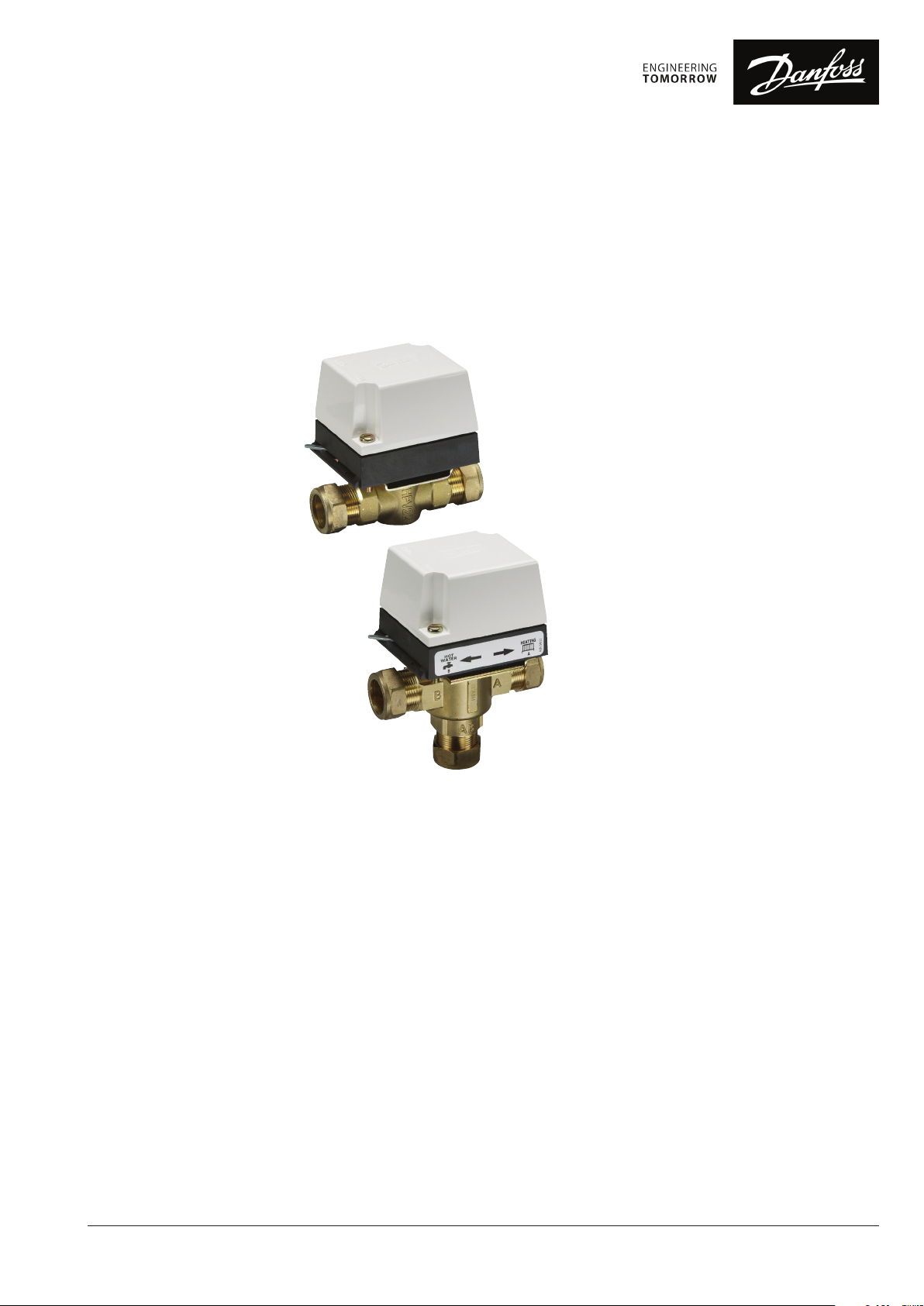
H Series Motorised Valves
Rotary-Shoe and Paddle Types
Features
These valves are developed to provide robustness,
dependability and operating efficiency. Designed
to withstand higher-than-usual test pressures,
support bearings at both top and bottom
of the shoe and paddle spindles and tough
polycarbonate actuator covers are some of the
features which ensure this added quality.
H Series valves are normally purchased as separate
valve bodies and actuators, but are available as sets
for some of the more popular combinations, see
Product Selection Guide for details. Actuators are
fitted to the valve bodies on site for convenience
of installation and serviceability.
The H Series Motorised Valves, working in
conjunction with time controls and thermostats,
are used in domestic and commercial central
heating, hot water and chilled water systems to
control the flow of water in the system.
They are designed and built for long term operation
under arduous conditions of high temperatures
and rapid pressure fluctuations.
Available as either rotary-shoe or paddle types,
H Series valves offer the specifier and installer
whatever he decides is appropriate for the job.
The range includes 2-port, 3-port diverter or midposition, metric sizes 15mm, 22mm and 28mm
with copper compression fittings and imperial
sizes 3/4” and 1” BSP threaded.
• Suitable for heating and cooling applications
• Proven reliability
• Long working life
• Actuators and valve bodies supplied separately
for convenience
• Easy installation and wiring
• Industry-standard fittings and wiring colours
• Robust construction
© Danfoss HS | 02/2019 | VDSKA312
1
1
Page 2
Datasheet
H Series Motorised Valves
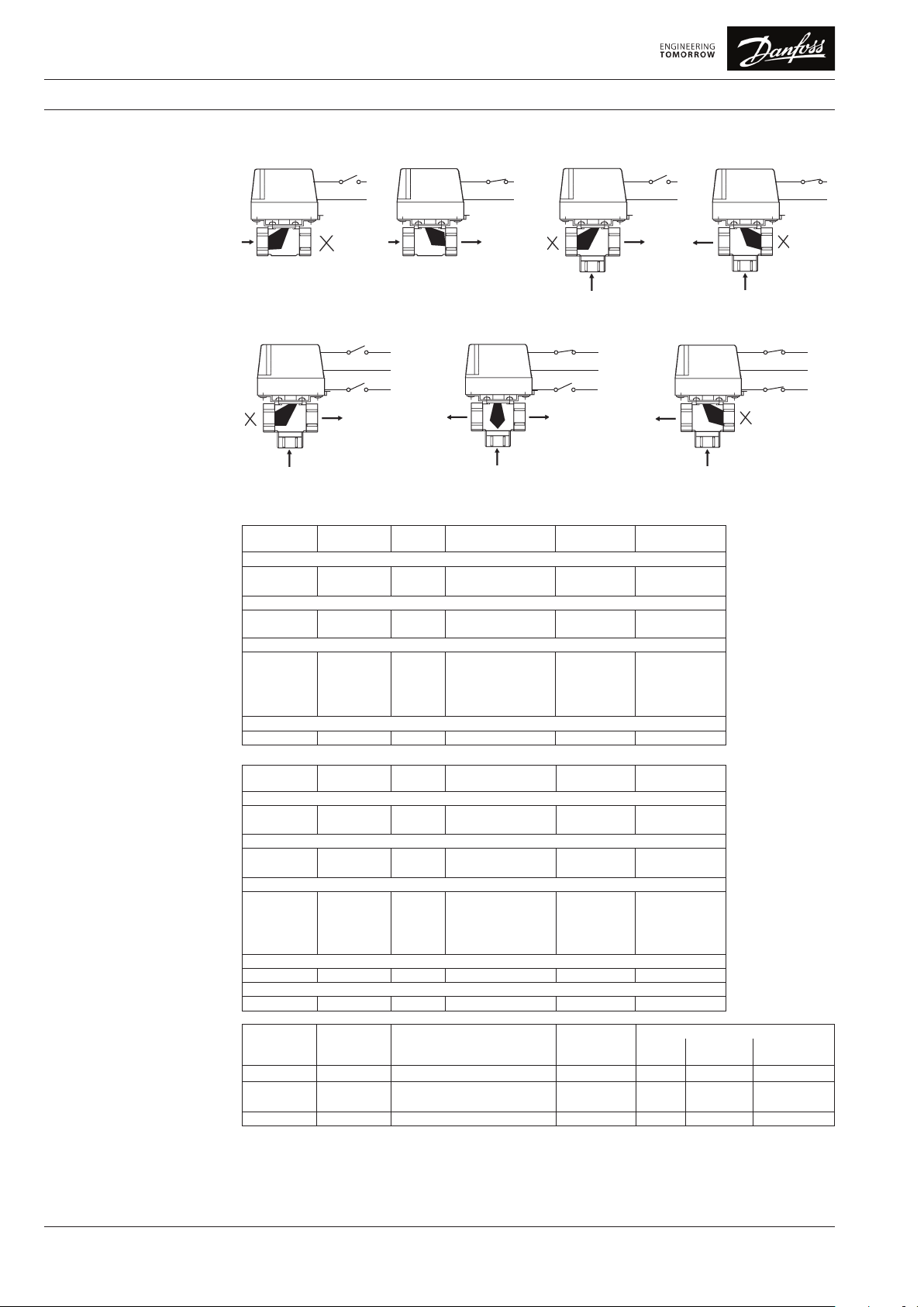
Valve/Actuator Configuration 2-Port Valves
A
3-Port Mid-Position Valves
A
AB
Ordering Codes
Valve Bodies Only
Note: All valve bodies can be used in
chilled water applications using 60/40%
Glycol/Water mix.
Type Order Code Size Description Kv (m3/hr)
Paddle Valves - 2 Port
HPV22B
HPV28B
Paddle Valves - 3 port
HSV3B22
HSV3B28
Shoe Valves - 2 Port
HPV15
HPV22
HPV28
HPV0.75
HPV1.0
Shoe Valve - 3 Port
HSV3 087N659900 22mm External compression 6.8 1.0
B
B
Brown
Blue
Brown
Blue
Grey
087N662200
087N662400
087N662500
087N663000
087N659600
087N659700
087N659800
087N659400
087N659500
3-Port Diverter Valves
L
N
A
L
N
L
22mm
28mm
22mm
28mm
15mm
22mm
28mm
¾”
1”
Brown
Blue
B
External compression
External compression
External compression
External compression
Internal compression
External compression
External compression
BSP
BSP
L
N
B
A
AB
A
Brown
Blue
Grey
15.0
15.0
Brown
Blue
B
AB
L
N
A
L
N
L
B
A
AB
Max. Differential
Pressure (Bar)
5.8
7.9
6.1
7.9
3.3
8.2
8.2
1.0
0.7
1.0
0.7
1.0
1.0
0.7
1.0
0.7
AB
Brown
Blue
Grey
Brown
Blue
B
L
N
L
N
L
Valve Body and Actuator Complete
Actuators Only
Type Order Code Size Description Kv (m3/hr)
Paddle Valves - 2 Port
HP22B
HP28B
Paddle Valves - 3 Port - Mid Position
HS3B
HS3B28
Shoe Valves - 2 Port
HP15
HP22
HP28
HP0.75
HP1.0
Shoe Valve - 3 Port
HS3D 087N661400 22mm External compression 6.8 1.0
Shoe Valves - 3 Port - Mid Position
HS3 087N661300 22mm External compression 6.8 1.0
Type Order Code Description
HPA2
HSA3D
HSA3CD
HSA3 087N658700 3 port, mid-position valve actuator SPST (Int. linked) •
087N664200
087N664400
087N664600
087N665100
087N660800
087N660900
087N661100
087N660200
087N660400
087N657900
087N658900
087N658800
22mm
External compression
28mm
External compression
22mm
External compression
28mm
External compression
15mm
Internal compression
22mm
External compression
28mm
External compression
¾”
BSP
1”
BSP
2 port, N.C. spring return actuator SPST •
3 port, diverter valve actuator
3 port, diverter valve actuator
5.8
7.9
6.1
7.9
3.3
8.2
15.0
8.2
15.0
Aux. Sw.
Details
SPST
SPDT
Max. Differential
Pressure (Bar)
1.0
0.7
1.0
0.7
1.0
1.0
0.7
1.0
0.7
Valve Body Compatibility
HPV...
HSV... 3 port
2 port
as diverter
•
•
HSV... 3 port
as mid-position
2
© Danfoss HS | 02/2019 | VDSKA312
Page 3

Datasheet
H Series Motorised Valves
Specifications
Actuator Wiring Detail
(Three-Port)
Valve Body Specifications
Body and trims
Top Seal Gasket
Spindle O Ring Seals
Paddle Material (Paddle type)
Shoe Material (Shoe type)
Max. Working Pressure (Bar)
Max. Operating Temperature (oC)
Maximum bypass/leakage through closed port
(shoe valves only)
Valve Actuator Specifications
Voltage Rating*
Maximum Power Consumption
Maximum Ambient Temperature
Opening Time
Closing Time
Auxiliary Switch Rating (if fitted)
Enclosure Rating
HSA3
Mid-Position
(Standard)
Blue (N)
Brown/White
(HTG Call)
Orange
(HWS Call)
Grey
(HWS Sat.)
HSA3D
M
Diverter
(Standard)
Hot stamped or die cast brass
THK-Ethylene propylene
Flurobon Fluro-elastomer
Nitrile elastomer
Carbon filled PTFE
10.0
95
15mm (inc. 1/2”) & 22mm (inc 3/4”) - 1 lt/hr @ 1 Bar Differential Pressure
28mm (inc 1”) - 1 lt/hr @ 0.7 Bar Differential Pressure
220/240 Vac, 50/60Hz
6 watts
45°C
< 35 seconds
< 20 seconds
3 (1) A, 220/240 Vac, 50/60 Hz
IP40
HSA3CD
Brown (L)
Blue (N)
Grey
Orange
M
Diverter
(Optional)
Brown (L)
Blue (N)
Orange
White
Grey
Actuator Wiring Detail
HPA2
(Two-Port)
M
(Standard)
Brown (L)
Blue (N)
Grey
Orange
Sizing The pressure drop across an H Series valve can be
determined from this Kv diagram.
The chart, which shows the Kv values of all H Series
valves as diagonal lines, can be used to determine
pressure drop when the flow rate is known (m3/h).
It can also be used to read off pressure drop values
when the heating load (kW) is known.
A vertical axis, scaled in kW for systems working at
temperature differences of either 11°C or 20°C, is
included in the chart.
Alternatively, pressure drop values can be
calculated using the formula:
∆P = Q
Kv
2
( )
Where:
Q = Flow rate (m3/h)
Kv = Co-efficient of Flow (m3/h)
∆P = Pressure Drop across the valve (bar)
Kv values of each valve type and size are shown in
the table opposite.
By following a vertical line downwards from this
point, a pressure drop of 0.11 bar can be read off
the horizontal axis at the base of the chart.
2) To determine the pressure drop across a 22mm.
2-port paddle valve (Kv = 5.8), for a 20 kW heating
load in a system working at an 11°C temperature
difference, follow the horizontal line from the 20
kW point on the appropriate right-hand vertical
axis until it crosses the diagonal 5.8 Kv line.
By following a vertical line downwards from this
point, a pressure drop of 0.072 bar can be read
off the horizontal axis at the base of the chart.
Examples of chart use:
1) To determine the pressure drop across a 22mm.
3-port paddle valve (Kv = 6.1), at a flow rate of
2.0 m3/h, follow the horizontal line from the 2.0
m3/h point on the left-hand vertical axis until it
crosses the diagonal 6.1 Kv line.
© Danfoss HS | 02/2019 | VDSKA312
3
Page 4

Datasheet
86.6
C
H Series Motorised Valves
Dimensions
3-PORT
63.0
D
63.0
D
86.6
73.4
A
BCH HW
73.4
Offset 8mm
Shoe Valves Paddle Valves2-PORT
73.4
A
73.4
CH HW
C
B
Offset 8mm
Valve Body Connections A B C D
Paddle Valves
Two-Port
HPV22B 22mm Ext. Comp. 90.6 17.5 112.5 27.6
HPV28B 28mm Ext. Comp. 90.6 22.4 128.0 27.6
Three-Port
HSV3B22 22mm Ext. Comp. 90.6 57.0 112.5 27.6
HSV3B28 28mm Ext. Comp. 90.6 71.5 128.0 27.6
Shoe Valves
Two-Port
HPV15 15mm Int. Comp. 87.1 13.8 83.5 24.1
HPV22 22mm Ext. Comp. 90.4 17.5 110.0 27.4
HPV28 28mm Ext. Comp. 93.6 24.3 108.0 30.6
HPV0.75 ¾” BSP 90.5 17.0 77.5 27.5
HPV1.0 1” BSP 93.6 20.6 87.3 30.6
Three-Port
HSV3 28mm Ext. Comp. 90.7 56.0 110.0 27.7
Valve bodies and actuators may be purchased separately for ease of installation and
serviceability, or in convenient sets. Actuators are fitted to valve bodies on site.
All dimensions are shown in millimetres.
Danfoss Limited
Heating Segment • heating.danfoss.co.uk • +44 (0)330 808 6888
Danfoss c an accept no respons ibility for pos sible errors in ca talogues, bro chures and other pr inted material. Da nfoss reserve s the right to alter its p roducts with out notice. This als o applies to
produc ts already on ord er provided that su ch alterations ca n be made without su bsequential cha nges being neces sary in speci cations alread y agreed.
All trade marks in this mate rial are proper ty of the respec tive companies . Danfoss and all Danf oss logotyp es are trademark s of Danfoss A/S. A ll rights reser ved.
44
© Danfoss HS | 02/2019 | VDSKA312
• E-mail: customerservice.uk@danfoss.com
 Loading...