

Page 1
Classified as Business
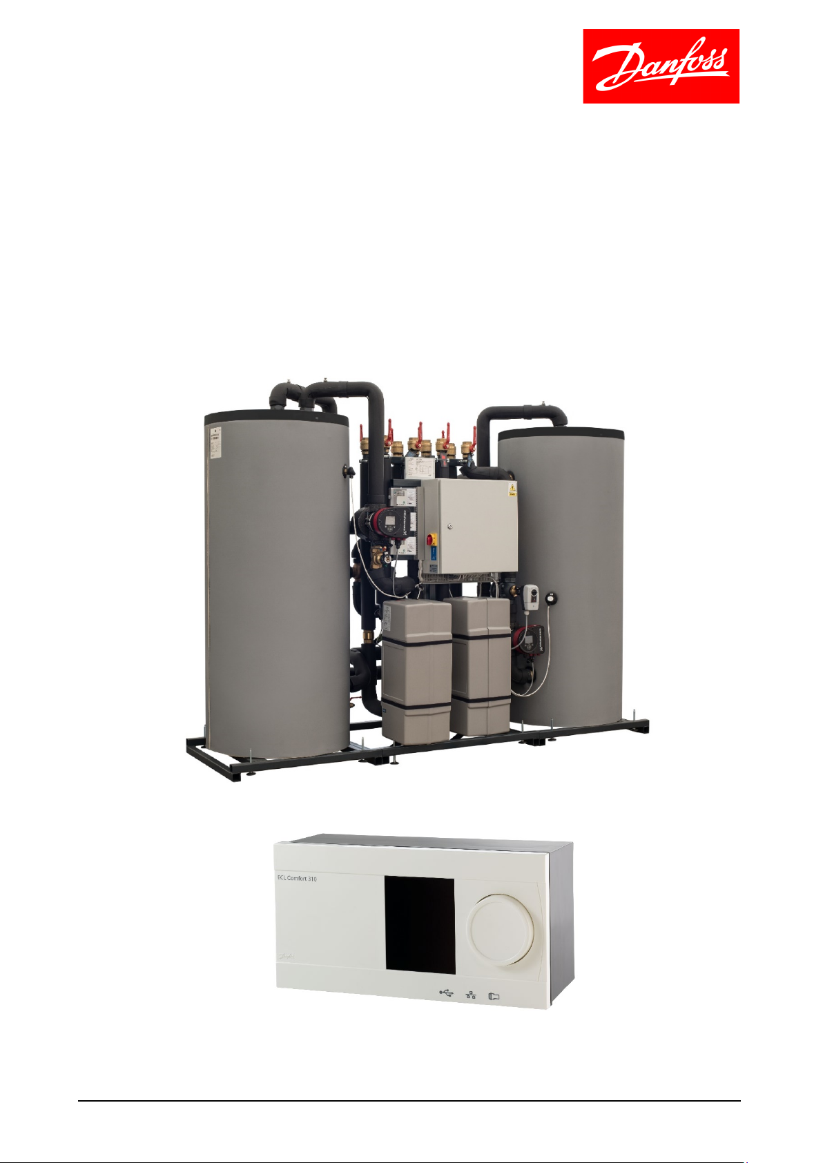
Operating Guide
HRU – Heat Recovery Unit
controlled with ECL Comfort 310 – P501.12 application
1
Page 2

Classified as Business
Contents
HRU Unit with ECL Comfort 310 – P501.12 ........................................................................................ 3
Primary function .............................................................................................................................. 4
Function description P501.12 ............................................................................................................. 5
Operation ......................................................................................................................................... 5
Control ............................................................................................................................................. 5
ECL operating mode .................................................................................................................... 5
Regulation ....................................................................................................................................... 6
Flow temperature ........................................................................................................................ 6
Sale of excess heat ....................................................................................................................... 6
Energy monitoring ...................................................................................................................... 6
Alarms .......................................................................................................................................... 7
Sensor overview .............................................................................................................................. 7
Configuration guide: ........................................................................................................................... 8
Heating circuit: ................................................................................................................................ 8
REMEMBER ................................................................................................................................... 8
Flow meter F1, F2 and F3 configuration ......................................................................................... 9
Configuration parameters for flow temperature from the HRU unit (S3) ................................... 10
Configuration parameters for the return temperature controller............................................... 11
Configuration parameters for optimisation ................................................................................. 12
Reg. parameter 1 applies to M1 controls ...................................................................................... 13
Reg. parameter 2 applies to M2 controls ...................................................................................... 14
Circuit 1, heating circuit ................................................................................................................ 15
Circuit 1, schedule 1 ...................................................................................................................... 16
Tank temperature. ......................................................................................................................... 17
Compensation T. ........................................................................................................................... 18
Reg. recovery. ................................................................................................................................ 19
Control par., export ....................................................................................................................... 20
Boost. ............................................................................................................................................. 21
Circuit 2, schedule 2....................................................................................................................... 22
Circuit 3, tank temperature. .......................................................................................................... 23
Circuit 3, schedule 3....................................................................................................................... 24
Connection of ECL 310 to ECL portal. ........................................................................................... 25
Integration with the cooling plant. ............................................................................................... 27
Configuration of heat requirement signals from HRU unit ............................................................. 27
Safety function. .............................................................................................................................. 27
2
Page 3
Classified as Business
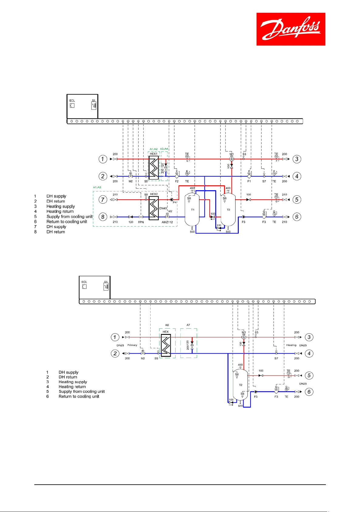
HRU Unit with ECL Comfort 310 – P501.12
Versions A1- A4
Versions A6- A7
3
Page 4

Classified as Business
Primary function
Utilisation of excess heat from CO2 refrigeration plants.
The unit prioritises heating of own plant before any sales to e.g. district heating suppliers.
In order to balance different usage patterns (temperatures and heating requirements) on the
heating side and the production of excess heat on the cooling side, the unit has been designed
as a buffer charging circuit.
This results in very stable and uniform charging, also ensuring a long service life for the CO2 heat
exchanger.
The flow temperature from the HRU unit is controlled by the building requirements (heating, hot
water or ventilation), either via signals from other ECLs or via Modbus from an existing SCADA
system.
In the event of possible sale of excess heat to the district heating supplier or other buyers, this
can be managed in such a way that a constant temperature is supplied to these buyers.
The HRU unit can send a reference signal to the cooling plant indicating how much heat can be
accumulated.
A safety function has been embedded to protect against boiling over on the water side.
4
Page 5

Classified as Business
Function description P501.12
Operation
The system is configured and monitored via the ECL Comfort 310 regulator or a PC/Mac/mobile
via the ECL portal.
Link to the ECL portal: ecl.portal.danfoss.com (Internet connection required)
Control
ECL operating mode
The mode of operation of the unit can be selected:
: AUTO The unit switches between comfort/saving mode via a time program.
Or this can be done via a heating request from a slave regulator (ECL Comfort 310)
The mode of operation for this application must be AUTO.
5
Page 6

Classified as Business
Regulation
Flow temperature
The flow temperature can be controlled using the following principles:
1. Fixed flow temperature or flow temperature based on the outdoor temperature from
the HRU unit
2. Determined by external reference (via Modbus)
3. Determined by references from other ECL 310 regulators for domestic hot water,
heating or ventilation units via ECL 485 bus communication
The control intelligence ensure that predominantly heat from buffer tanks is used. If, during
certain periods, this is not adequate, auxiliary heat can be added from external heating sources
such as district heating or boiler systems, etc.
The charging temperature is controlled in accordance with the desired buffer temperature and
the cooling plant load, so that maximum energy is transferred from the cooling plant at all times.
This ensures that minimal energy is discharged from the gas cooler on the roof.
Cooling circuit
A signal is transmitted to the cooling plant about how much energy can be accumulated so that,
during periods without the possibility for accumulation, energy is not transferred from the CO2
exchangers to the buffer charging system.
Sale of excess heat
In the event of sale or export of excess heat, energy is pumped out via the same supply
connection used to buy heat using a frequency-controlled booster pump controlled by the
differential pressure and the desired sales flow temperature.
Energy monitoring
If desired, consumption data can be collected via the ECL 310 from heat, water and electricity
meters via M-bus connections. The data is transferred to Danfoss' ECL portal.
The energy data is logged on an hourly basis and can also be retrieved for use with third-party
energy management systems, in which it may be possible to create an overview of the total
energy consumption, corrected for heating degree days, allowing for comparison of the energy
consumption of buildings in connection with energy management.
6
Page 7
Classified as Business
S1
Outdoor temperature
S2
Return temperature, CO2 to gas cooler
S3
Flow temperature from HRU to the heating
circuit
S4
Charging temperature to accumulation tank
S5
Return temperature to district heating
S6
Top temperature in the accumulation tank
S7
Return temperature from the heating circuit
S8
Bottom temperature in the accumulation tank
S9
Flow temperature, sale of excess heat
S10
Return temperature from the accumulation
tank
S11
CO2 temperature from the cooling
compressor
Alarms
Flow failure in charging circuit
An alarm can be configured so that, in the event of a flow failure in the charging circuit (flow
meter F3), can stop the circulation pump P3, and at the same time 0V will be transmitted to the
cooling plant so that the three-way valve on the CO2 side leads the gas directly to the gas cooler
on the roof.
The alarm is given in accordance with the configured time delay.
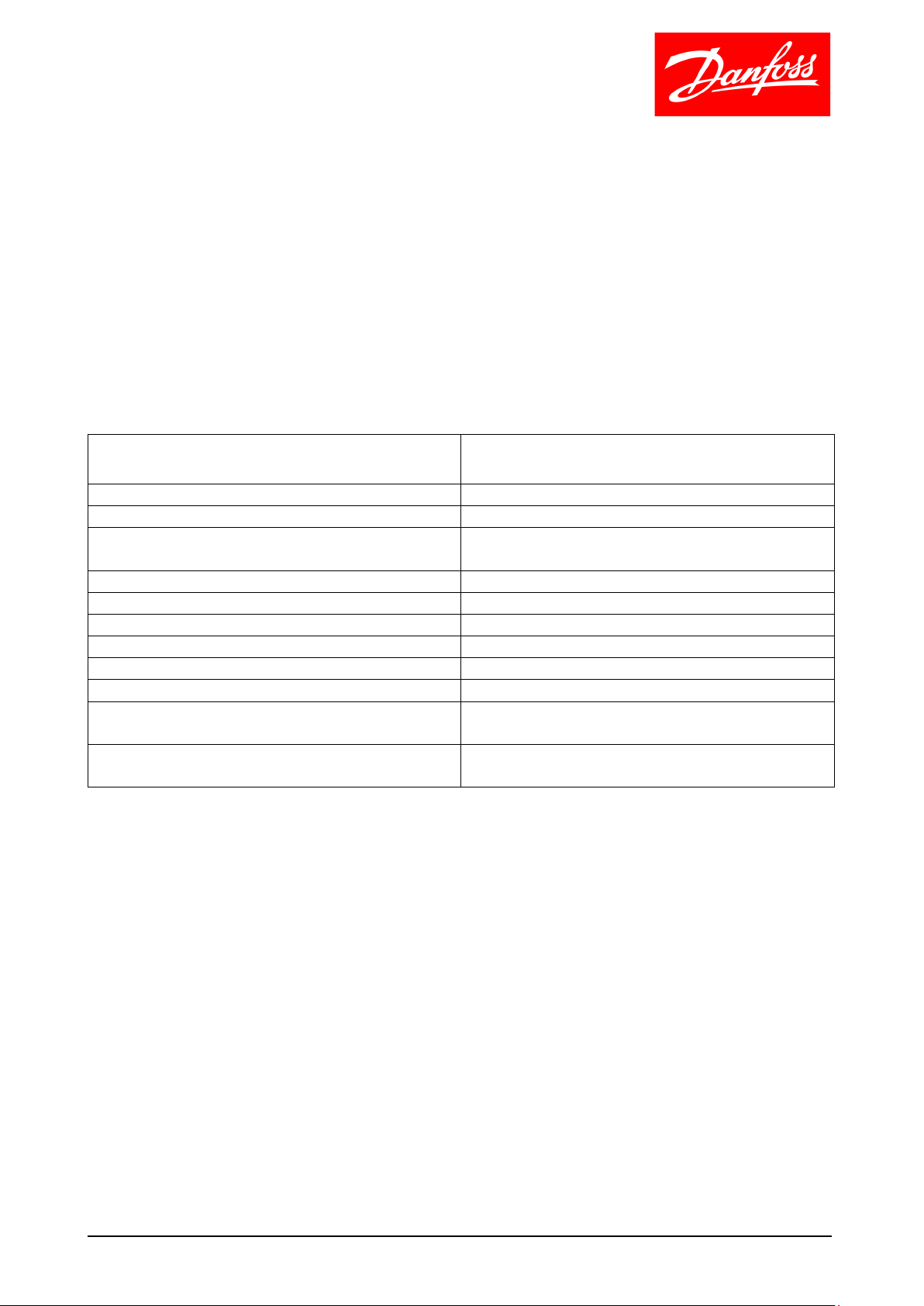
Sensor overview
Sensor ID Sensor description
7
Page 8

Classified as Business
Configuration guide:
Heating circuit:
The mixing circuit (M1) operates in three phases:
1: 100% use of recovered heat
2: mixture of recovered heat and auxiliary heat
3: 100% use of auxiliary heat
Note: in the event of 100% use of recovered heat, mixing takes place via the purchase exchanger with
a closed M2 valve.
REMEMBER
The return temperature from the heating plant (S7) must always be as low as possible, as only
five degrees lower could have a major impact on the utilisation of CO2 heat recovery. For radiator
heating, the return temperature at S7 should ideally be around 30-35 degrees, and for
underfloor heating it should be 20-25 degrees.
It is therefore crucial to the utilisation of excess heat that the heating circuit is optimised and
correctly configured.
The mixing circuit (M1) is configured as an ordinary mixing circuit. The desired flow temperature
from the HRU unit (R3 reference) can be configured as a fixed temperature or a flow
temperature based on the outdoor temperature. It can also originate from another ECL 310 or
via Modbus from an existing SCADA system.
Remember to configure night setback in the heating system. This means that less energy is used
from the accumulation tanks at night. Several refrigerators are now also covered at night and, in
such situations, less energy is generated for heat recovery.
8
Page 9
Classified as Business
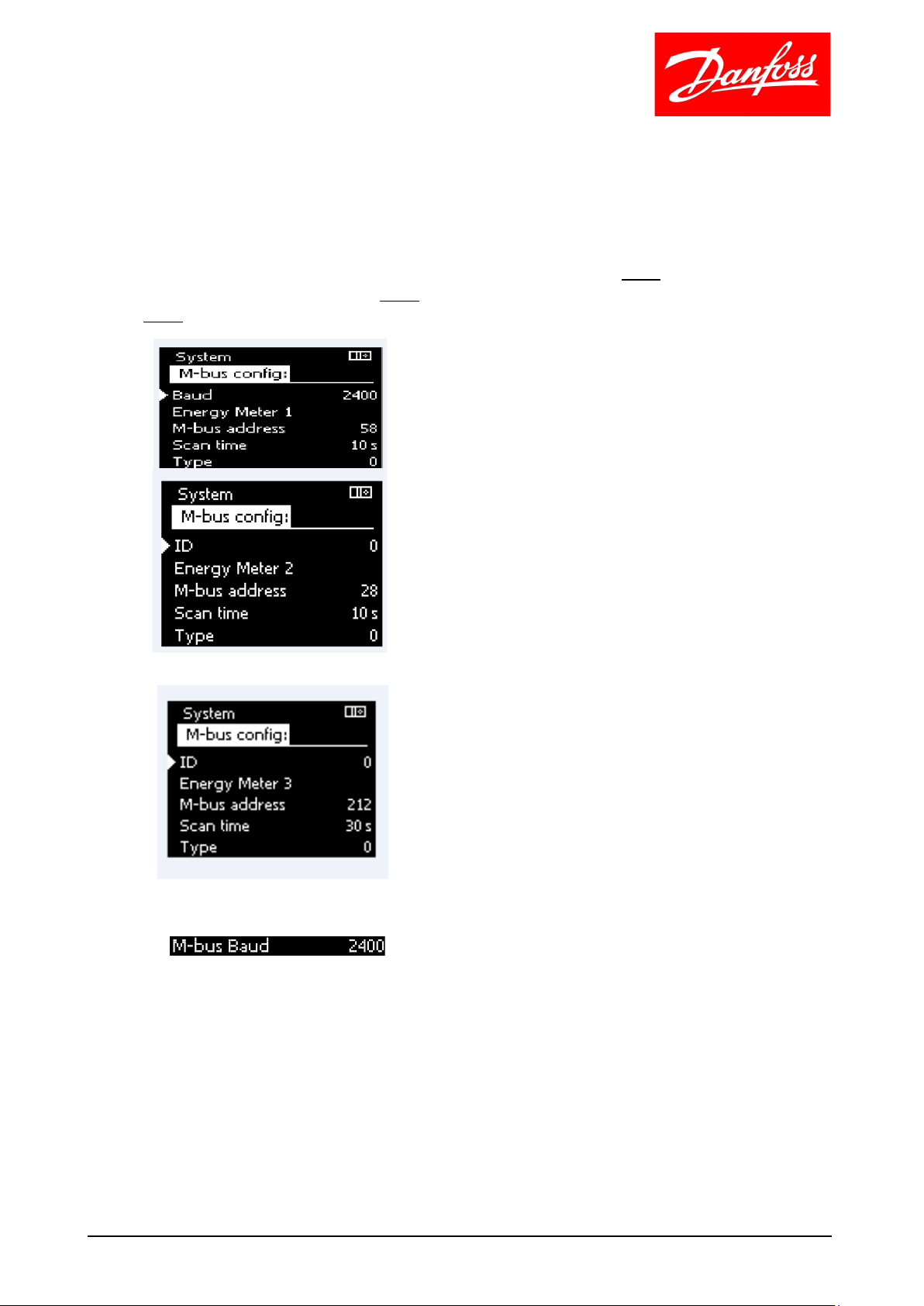
Flow meter F1, F2 and F3 configuration
Menu -> Settings -> Flow temperature
• The M-bus from flow meters is connected to the terminals 37 and 38 in the ECL 310.
• All flow meters must be configured in settings. Flow meter F1 must be configured as
Energy meter 1, flow meter F2 must be configured as Energy meter 2 and flow meter F3
must be configured as Energy meter 3.
• Energy meter F3 - shows how much energy is being recovered.
• It is important to ensure that the Baud rate has been set to 2400 for all connected meters.
9
Page 10

Classified as Business
Configuration parameters for flow temperature from the HRU unit (S3)
Menu -> Circuit 1 -> Settings -> Flow temperature
The weather compensated flow temperature can be configured here
"Frost protection T" is the minimum temperature for S3.
"Desired T" if external override has been created for an available input, the desired fixed flow
temperature (R3) from the HRU unit can be configured here.
The minimum and maximum flow temperature (R3) can be configured here.
10
Page 11

Classified as Business
Configuration parameters for the return temperature controller
Menu -> Circuit 1 -> Settings -> Return temp. Limit
The return temperature controller applies to the temperature at sensor S5.
Here you configure the highest permitted temperature desired at S5.
When this limit is exceeded, the 'Max. amplification' setting can be adjusted to determine the
impact this will have on R3.
11
Page 12

Classified as Business
Configuration parameters for optimisation
Menu -> Circuit 1 -> Settings -> Optimisation
If an external signal indicating the desired flow temperature (R3) is not received, these settings
will apply together with the "Flow temperature" settings.
If a schedule has been configured for comfort/saving mode:
• "Auto-save" will gradually reduce the reduction size and saving mode is cancelled when
the configured value is reached.
• "Ramp", change from saving to comfort mode can take place slowly over the configured
time.
12
Page 13

Classified as Business
Reg. parameter 1 applies to M1 controls
Menu -> Circuit 1 -> Settings -> Reg. parameter 1
*Parameters apply to the M1 temperature controls (S3).
*Parameters apply to the mixing phase, i.e. when mixing of recovered heat and purchased heat
takes place. Flow is associated with flow meter F2. Temperature controls (S3) are controlled by
M2.
*Here, the anticipated flow temperature from auxiliary heat (district heating, boiler or other) is
configured.
13
Page 14
Classified as Business
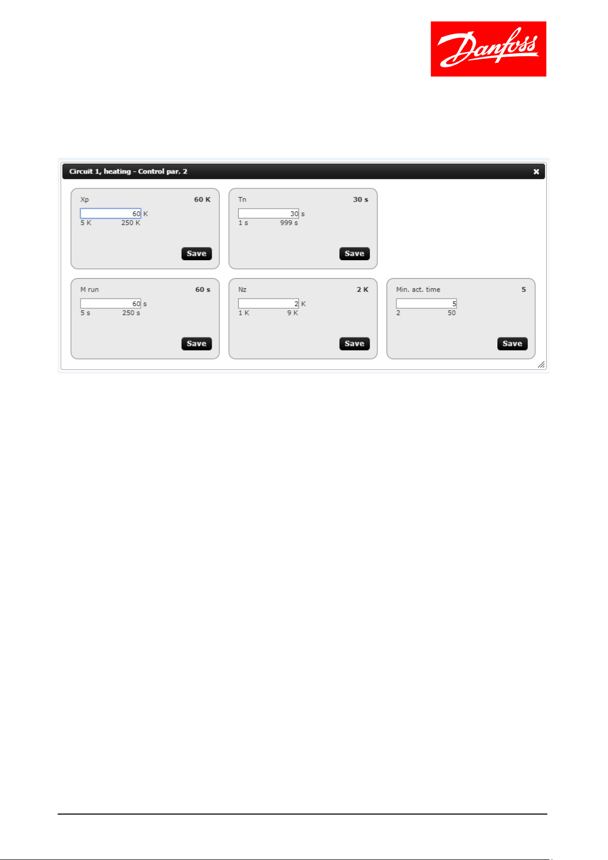
Reg. parameter 2 applies to M2 controls
Menu -> Circuit 1 -> Settings -> Reg. parameter 2
Here, control parameters (M2) are configured for the desired flow temperature R3.
14
Page 15

Classified as Business
Circuit 1, heating circuit
Menu -> Circuit 1 -> Settings -> Application
"Slave, difference" is the temperature that is added to the highest temperature requirement that
may be received from one or more slave regulators.
"Mode of operation" – Here you select the mode of operation in which the HRU unit will run
1: All three phases: recovered / mix / auxiliary heat
2: Phases: recovered / auxiliary heat
3: 100% use of recovered heat
15
Page 16

Classified as Business
Circuit 1, schedule 1
Menu -> Circuit 1 -> Settings -> Schedule 1
If an external signal indicating the desired flow temperature (R3) is not received, this schedule
will apply to the configured comfort and saving mode temperatures.
16
Page 17

Classified as Business
Tank temperature.
Menu -> Circuit 2 -> Settings -> Tank temperature
Here, you configure the desired temperature in the buffer/charger tanks and when charging
should start and stop.
17
Page 18

Classified as Business
Compensation T.
Menu -> Circuit 2 -> Settings -> Compensation T
The permitted difference between temperatures S10 and S2 at high and low charging
temperature respectively ("High X" and "Low X") can adjust the desired charging temperature
(R4) with a desired amplification factor "Max. amplification".
18
Page 19

Classified as Business
Reg. recovery.
Menu -> Circuit 2 -> Settings -> Reg. recovery
The desired charging temperature in relation to the tank temperature is configured in "Charging
difference".
In "V out. min." you can configure the desired minimum charging flow given by P3.
If the setting "Intgr. Time" is configured as other than "0", the "My running time" and "PWM
period" settings can be configured to specify how often the pump will stop and start to achieve
less flow.
19
Page 20

Classified as Business
Control par., export
Menu -> Circuit 2 -> Settings -> Control par., export
The desired sale/export temperature is configured in "Desired T".
Requirements for the tank top temperature (S6) before export must be configured in "Start T".
Requirements for the tank bottom temperature before export must be configured in "Start
difference" as "Start T" + "Start difference".
As shown, export starts when both requirements have been met:
S6 > ”Start T” > 72 °C
S8 > ”Start T” + ”Start difference” > 72-22 = 50 °C
As shown, export stops when:
S6 < ”Start T”+ ”Stop difference” < 72-3 = 69 °C
Or if domestic hot water requirements are received from another ECL 310 if the setting "VV
priority" is ON.
20
Page 21

Classified as Business
Boost.
Menu -> Circuit 2 -> Settings - > Boost
Boost is an expression of how much energy the HRU unit can buffer via heat recovery. This signal
(0-10VDC) the ECL 310 sends to the cooling plant.
During operation, the minimum signal ("V out. min."), here shown as 20%, and the cooling plant
will switch the bypass valve next to the CO2 exchanger. If the buffer charging tanks were to fill up
completely, 0% (0 VDC) will be transmitted to the cooling plant.
"V out. min. and max." in the abovementioned 20-70% corresponds to 2-7 VDC.
"Depended on export" ON: This setting can increase the "Boost" signal to the cooler in the event
of export/sale of recovered heat. This happens if the tank temperature (S6) is lower than the
desired start temperature for export "Start T," or if the current charging temperature (S4) is lower
than the desired tank temperature (R6).
"Depended on export" OFF: This setting can increase the "Boost" signal to the cooler. This
happens only if the current charging temperature (S4) is lower than the desired tank
temperature (R6).
21
Page 22

Classified as Business
Circuit 2, schedule 2.
Menu -> Circuit 2 -> Settings -> Schedule 2
Here, you can configure a Schedule for when you want to be able to export excess energy.
22
Page 23

Classified as Business
Circuit 3, tank temperature.
Menu -> Circuit 3 -> Settings -> Tank temperature
If a hot water tank is installed between the CO2 exchanger and the HRU unit, comfort and saving
temperatures can be configured here.
Here, you can also configure when the hot water tank will start and stop charging.
23
Page 24

Classified as Business
Circuit 3, schedule 3.
Menu -> Circuit 3 -> Settings -> Schedule 3
Here, you can configure a schedule for when you want comfort and saving temperatures in the
hot water tank.
24
Page 25

Classified as Business
Connection of ECL 310 to ECL portal.
Menu -> System -> Address type
Connect the network cable with the Internet connection to your ECL Comfort 310
Activate automatic network addressing
Set "ECL Portal" to "ON" and view your serial number and access code under "Server info"
25
Page 26

Classified as Business
Start your PC and open the link ecl.portal.danfoss.com , create a user account by pressing on the
'new user' link and follow the instructions on screen.
You only need to do this the first time you subscribe an ECL Comfort 310
Subscribe the ECL using the serial number and access code.
You are now ready to remote control and monitor your HRU unit.
26
Page 27

Classified as Business
Integration with the cooling plant.
Note:
It is important to install a 6 bar safety valve as close as
possible to the CO2 exchanger in the charging circuit.
An S4 sensor must be installed in the CO2 exchanger as
shown in the image below.
Configuration of heat requirement signals from HRU unit
The galvanically separated 0-10VDC signal from the ECL 310 informs the cooling plant of how
much energy the HRU unit can recover.
It is important that this signal is configured in the cooling plant automation so that the CO2 gas
bypasses the CO2 exchanger and is directed to the gas cooler when no more heat can be
recovered in the HRU unit.
The configuration should be set up as follows:
0VDC CO2 100% bypasses the heat recovery exchanger
0.5 – 2.5VDC CO2 is directed 100% through the heat recovery exchanger
2.5 – 10VDC can be used to increase the operating pressure in the cooling plant to make more
heat available for recovery
Safety function.
If the flow in the charging circuit during charging is zero for a longer period than configured, the
ECL 310 in the HRU unit will send 0VDC to the cooling plant automation, which will switch the
bypass valve so that the CO2 gas is led directly to the gas cooler on the roof.
The cooling plant automation must be equipped with a sensor on the water side of the CO2
exchanger to protect against boiling.
27
 Loading...