

Page 1
Data sheet
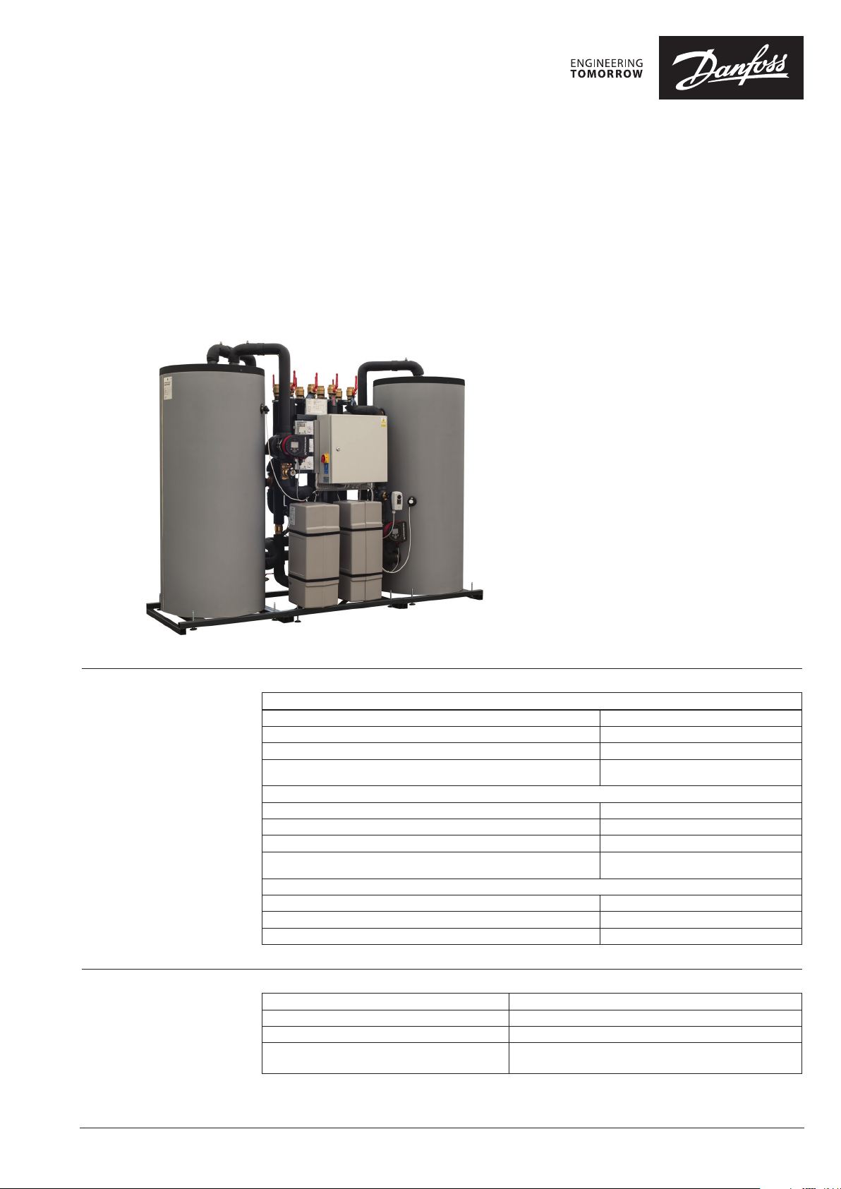
HRU – Heat Recovery Unit
General description
and application
Danfoss Heat Recovery Unit provide the link
between a CO₂ refrigeration systems and the
heating installation. It is developed and designed
for recovery of waste heat from refrigeration
installations, where CO₂ is used as medium, to
heat supermarkets (hot tap water, heating, air
handling units) and enables selling surplus heat
back to the district heating network. Danfoss
HRU can be used in installations with different
external heat supply, such as District energy,
boiler or other heat source.
Characteristic:
• Heating demand: 22-540 kW
• Maximum recovered heat from C0₂ pack up
to 50-400kW
Two different solutions based on store size:
1. one- tank solution - for small stores up to 1500 m
2. two-tanks solution - for medium and large stores
Standard layout in 6 versions:
• indirect connection (type A2,A6) or directly
connection (type A4,A7).
• indirect connection (type A1) or connection
to DHU (type A3), designed for areas where it is
possible to sell heat to DHU network.
Maximum operating
parameters
Materials
Primary
Maximum permissible supply temperature, primary* 90 °C
Maximum permissible operating pressure, primary 10 bar
Rated pressure, primary PN 10
Maximum permissible flow primary
Secondary heating
Maximum permissible temperature, secondary* 90 °C
Maximum permissible operating pressure, secondary (A1, A2) – 6 bar, (A3, A4, A6, A7) – 10 bar
Minimum required pressure (static), water supply 1,0 bar
Maximum permissible flow secondary
CO heat supply
Maximum permissible temperature secondary 90 °C
Maximum permissible operating pressure, secondary (A1, A2) – 6 bar, (A3, A4, A6, A7) – 10 bar
Minimum required pressure (static), water supply 1,0 bar
* For higher te mperatures – contac t Danfoss
Pipes, fittings, flanges, valves (Primary side) P235GH, EN-GJL-250 (GG25), CuZn36Pb2As
Pipes, fittings, flanges, valves (Heating side) P235GH, EN-GJL-250 (GG25), CuSn5Pb5Zn5-C (RG-5)
Heat exchanger 1.4404 with Cu solder
Insulation Elstomeric Foam (Nitrile Rubber) – λ = 0.035 W/mK (piping)
PU foam – λ = 0.029 W/mK (heat exchanger)
15 m³/h for v= 1,2 m/s ( A1, A2, A3, A4)
3 m³/h for v= 1,2 m/s ( A6,A7)
15 m³/h for v= 1,2 m/s ( A1, A2, A3, A4)
3 m³/h for v= 1,2 m/s ( A6,A7)
© Danfoss | 2018.08
VD.MG.D2.02 | 1
Page 2
Data sheet HRU – Heat Recovery Unit
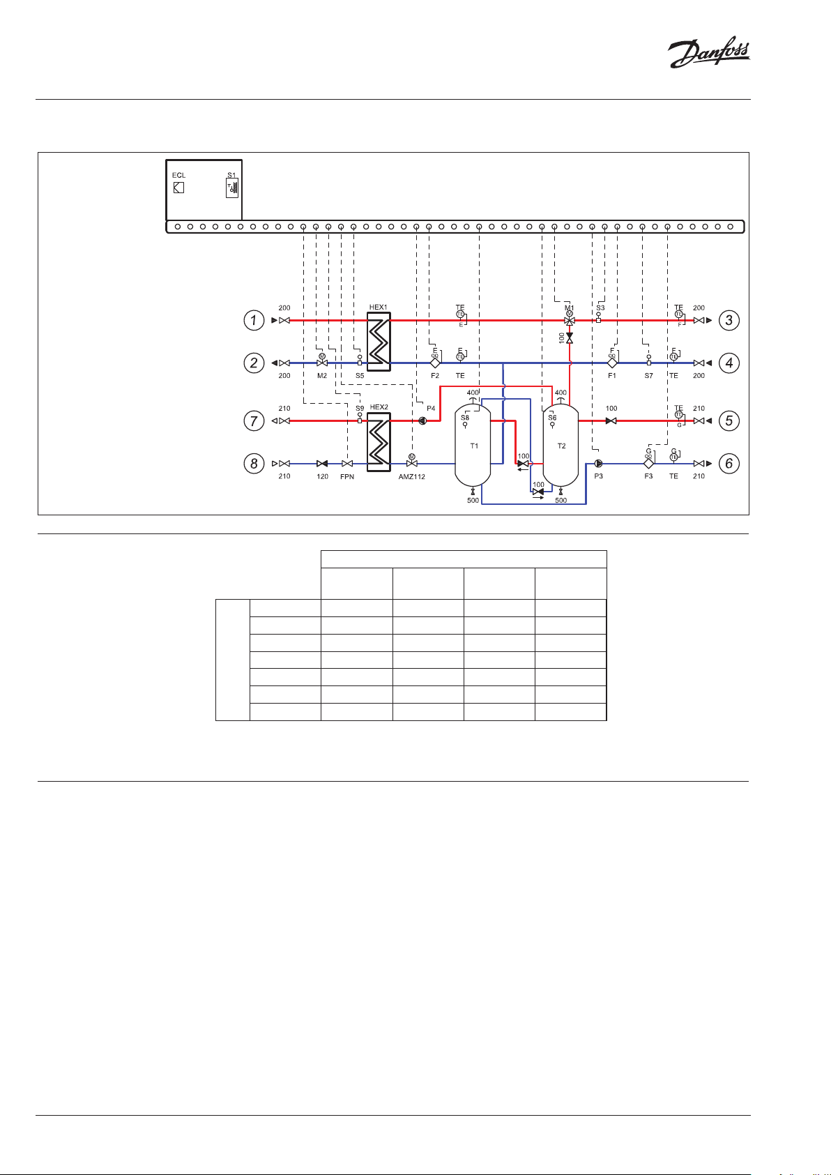
Circuit diagram A1 Indirect connection to DHU network with possibility of transfer heat outside heating system
Twotanks solution
1 DH supply
2 DH return
DN40
*
DN40
3 Heating supply
4 Heating return
5 Supply from
cooling unit
Return to
cooling unit
DN40
DN40
7 DH supply
DH return
* Connections DH⁄HE: up to 216 KWDN 40 up to 337 kWDN50 up to 540 kWDN65
*
A1 selection list
CO2 output [kW] (sales demand)
up to
100
up to
150
up to 22 146B9108 146B9109
up to 54 146B9120 146B9121 146B9122 146B9123
up to 85 146B9126 146B9127 146B9128 146B9129
up to 135 146B9132 146B9133 14 6B9134 146B9135
[kW]
up to 216 146B9138 146B9139 146B9140 146B9141
up to 337 146B9144 146B9145 146B9146 146B9147
Heating demand
up to 540 14 6B9150 146B9151 14 6B9152 14 6B9153
Function Waste heat from CO system is transferred via
CO heat exchanger * using water as medium,
into supply storage tanks T2 and T1.
The temperature sensor (S6) check the
temperature in tank (T2) and send a signal to
a 3-way valve (M1), which will open and heat
accumulated in tanks will be transferred into the
heating circuit.
Lower demand for heat will cause closing of the
controlling valve (M2) and reduce or cut the need
for energy from the external heat source. The
temperature sensor (S8) control the pump (P3)
and when the temperature reaches the desired
level and no more heat can be accumulated.
Secondary heat meters (F1 and F2) are measuring
flow and heat meter F3 on the charging circuit
calculates the recovered energy.
up to
300
up to
400
The primary function is to recover as much
energy as possible and secondary as high
temperature as possible
We always prioritize usage of heat
recovered from cooling unit before
supplying from external heat source
A1 version offers returning heat back into
the DHU network or other external network
via heat exchanger HEX2
If the recovered energy is more than the
stores can reuse the pump P4 is activated
so this energy can be sold to the district
heating
2 | © Danfoss | 2018.08
* CO₂ HEX is not included in the d elivery of HRU, but is part of the coolin g unit
VD.MG.D2.02
Page 3
Data sheet HRU – Heat Recovery Unit
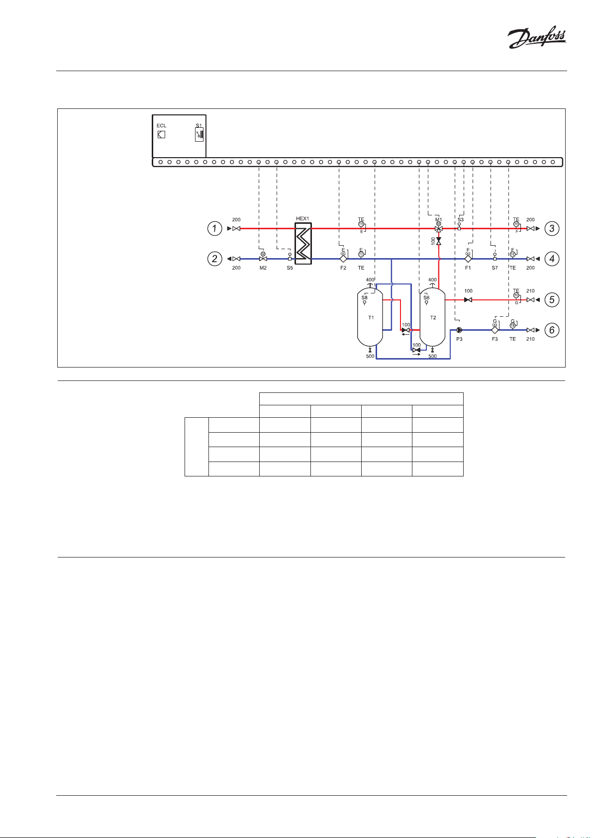
Circuit diagram A2 Indirect connection to DHU network
Twotanks solution
DN40* DN40*
1 DH supply
2 DH return
3 Heating supply
4 Heating return
5 Supply from
cooling unit
Return to
cooling unit
DN40
* Connections DH⁄HE: up to 216 KWDN 40 up to 337 kWDN50 up to 540 kWDN65
A2 selection list
CO2 output [kW]
up to 100 up to 150 up to 300 up to 400
up to 135 146B9164 146B9165
up to 216 146B9168 146B9169 146B9170
up to 337 14 6B9173 146B9174 146B9175 146B9176
Heating
up to 540 146B9179 146B9180 146B9181 146B9182
demand [kW]
Function Waste heat from CO₂ system is transferred via
CO₂ heat exchanger * using water as medium,
into supply storage tanks T2 and T1.
The temperature sensor (S6) check the
temperature in tank (T2) and send a signal to
a 3-way valve (M1), which will open and heat
accumulated in tanks will be transferred into the
heating circuit. Lower demand for heat will cause
closing of the controlling valve (M2) and reduce
or cut the need for energy from the external heat
source.
The temperature sensor (S8) controls the pump
with PWM signal (P3) and when the temperature
reaches the desired level and no more heat can
be accumulated.
In two-tanks solution application, secondary
heat meters (F1 and F2) are measuring flow and
heat meter F3 on the charging circuit calculates
the recovered energy.
* CO₂ HEX is not inclu ded in the delivery of H RU, but is part of the cooling uni t)
The primary function is to recover as much
energy as possible, and secondary as high
temperature as possible.
We always prioritize usage of heat recovered
from cooling unit, before supplying from
external heat source.
VD.MG.D2.02
© Danfoss | 2018.08 |PL
Page 4

Data sheet HRU – Heat Recovery Unit
Circuit diagram A3 Direct connection to DHU network with possibility of transfer heat outside heating system
Twotanks solution
1 DH supply
2 DH return
3 Heating supply
DN40* DN40*
4 Heating return
5 Supply from
Cooling unit
Return to
cooling unit
7 DH supply
DN40 DN40
DH return
* Connections DH⁄HE: up to 216 KWDN 40 up to 337 kWDN50 up to 540 kWDN65
A3 selection list
CO2 output [kW] (Sales demand)
up to
100
up to
150
up to 22 146B9191 146B9192
up to 54 146B9203 14 6B9204 146B9205 146B9206
up to 85 146B9209 146B9210 146 B9211 146B9212
up to 135 146B9215 146B9216 146B9217 146B9218
[kW]
up to 216 146B9221 146B9222 146B9223 146B9224
up to 337 146B9227 146B9228 146B9229 146B9230
Heating demand
up to 540 146B9233 146B9234 146B9235 146B9236
Function Waste heat from CO system is transferred via
CO heat exchanger * using water as medium,
into supply storage tanks T2 and T1.
The temperature sensor (S6) check the
temperature in tank (T2) and send a signal to
a 3-way valve (M1), which will open and heat
accumulated in tanks will be transferred into the
heating circuit.
Lower demand for heat will cause closing of the
controlling valve (M2) and reduce or cut the need
for energy from the external heat source. The
temperature sensor (S8) control the pump (P3)
and when the temperature reaches the desired
level and no more heat can be accumulated.
Secondary heat meters (F1 and F2) are measuring
flow and heat meter F3 on the charging circuit
calculates the recovered energy.
up to
300
up to
400
The primary function is to recover as much
energy as possible and secondary as high
temperature as possible
We always prioritize usage of heat recovered
from cooling unit before supplying from
external heat source
A3 version offers returning heat back into the
DHU network or other external network via
heat exchanger HEX2
If the recovered energy is more than the
stores can reuse the pump P4 is activated so
this energy can be sold to the district heating
4 | © Danfoss | 2018.08
* CO₂ HEX is not included in the d elivery of HRU, but is part of the coolin g unit
VD.MG.D2.02
Page 5

Data sheet HRU – Heat Recovery Unit
Circuit diagram A4 Direct connection to DHU network
Twotanks solution
1 DH supply
2 DH return
3 Heating supply
DN40* DN40*
4 Heating return
5 Supply from
Cooling unit
Return to
cooling unit
7 DH supply
DH return
* Connections DH⁄HE: up to 216 KWDN 40 up to 337 kWDN50 up to 540 kWDN65
DN40
A4 selection list
CO2 output [kW]
up to 100 up to 150 up to 300 up to 400
up to 135 14 6B9247 146B924 8
up to 216 146B9251 14 6B9252 146B9253
up to 337 146B9256 146B9257 14 6B9258 146B9259
Heating
up to 540 146B9262 146B9263 146B9264 14 6B9265
demand [kW]
Function Waste heat from CO₂ system is transferred via
CO₂ heat exchanger * using water as medium,
into supply storage tanks T2 and T1.
The temperature sensor (S6) check the
temperature in tank (T2) and send a signal to
a 3-way valve (M1), which will open and heat
accumulated in tanks will be transferred into the
heating circuit. Lower demand for heat will cause
closing of the controlling valve (M2) and reduce
or cut the need for energy from the external heat
source.
The temperature sensor (S8) controls the pump
with PWM signal (P3) and when the temperature
reaches the desired level and no more heat can
be accumulated.
In two-tanks solution application, secondary
heat meters (F1 and F2) are measuring flow and
heat meter F3 on the charging circuit calculates
the recovered.
* CO HEX is not included in the delivery of HRU but is part of the cooling unit
The primary function is to recover as much
energy as possible, and secondary as high
temperature as possible.
We always prioritize usage of heat recovered
from cooling unit, before supplying from
external heat source.
VD.MG.D2.02
© Danfoss | 2018.08 |PL
Page 6

Data sheet HRU – Heat Recovery Unit
Circuit diagram A6 Direct connection to DHU network with possibility of transfer heat outside heating system
Onetank solution
1 DH supply
2 DH return
3 Heating supply
4 Heating return
5 Supply from
Cooling unit
Return to
cooling unit
A6 selection list
CO2 output [kW]
up to 100
up to 22 146B940 0
up to 54 146B9401
Heating
up to 85 146B94 02
demand [kW]
Function Waste heat from CO₂ system is transferred via
CO₂heat exchanger * using water as medium,
into supply storage tank T2. The temperature
sensor (S6) check the temperature in tank (T2)
and send a signal to a 3-way valve (M1), which
will open and heat accumulated in tank will
be transferred into the heating circuit. Lower
demand for heat will cause closing of the
controlling valve (M2) and reduce or cut the
need for energy from the external heat source.
The temperature sensor (S8) control the pump
with PWM signal (P3) and when the temperature
reaches the desired level and no more heat
can be accumulated. In one-tank solution
application, heat meter F3 on the charging circuit
calculates the recovered energy.
The primary function is to recover as much
energy as possible, and secondary as high
temperature as possible.
We always prioritize usage of heat recovered
from cooling unit, before supplying from
external heat source.
6 | © Danfoss | 2018.08
* CO₂ HEX is not included in the d elivery of HRU, but is part of the coolin g unit
VD.MG.D2.02
Page 7

Data sheet HRU – Heat Recovery Unit
Circuit diagram A7 Direct connection to DHU network
Onetank solution
1 DH supply
2 DH return
3 Heating supply
4 Heating return
5 Supply from
Cooling unit
Return to
cooling unit
A7 selection list
CO2 output [kW]
up to 100
up to 22 146B9403
up to 54 146B940 4
Heating
up to 85 146B9405
demand [kW]
Function Waste heat from CO₂ system is transferred via
CO₂heat exchanger * using water as medium,
into supply storage tank T2. The temperature
sensor (S6) check the temperature in tank (T2)
and send a signal to a 3-way valve (M1), which
will open and heat accumulated in tank will
be transferred into the heating circuit. Lower
demand for heat will cause closing of the
controlling valve (M2) and reduce or cut the
need for energy from the external heat source.
The temperature sensor (S8) control the pump
with PWM signal (P3) and when the temperature
reaches the desired level and no more heat
can be accumulated. In one-tank solution
application, heat meter F3 on the charging circuit
calculates the recovered energy.
The primary function is to recover as much
energy as possible, and secondary as high
temperature as possible.
We always prioritize usage of heat recovered
from cooling unit, before supplying from
external heat source.temperature as possible.
We always prioritize usage of heat recovered
from cooling unit, before supplying from
external heat source.
VD.MG.D2.02
* CO₂ HEX is not included in the d elivery of HRU, but is part of the coolin g unit
© Danfoss | 2018.08 |PL
Page 8

Data sheet HRU – Heat Recovery Unit
Dimensions
Twotanks solution (A1 A2 A3 A4)
max. 2000 mm
max. 2800 mm
8
23
5
Component overview
max. 1200 mm
4
1
67
Item ( see circuit diagram) Description
100, 120, 125 Check valve
200, 210 Shut-off Ball valve
AMZ112 Motorized ON/OFF ball valve
FPN Flowswitch DN25
400 Air vent
500 Drain
F1F2F3 Heat meter
M1 Motorized Control valve HE 3way VRB+AMV
M2 M3 Motorized Combi valve AHQM + AMV
P3 Pump
P4 Pump ver A1 A3
S1 Outdoor temperature sensor ESMT
S3 S5 S7S9 Surface temperature sensor ESM
S6 S Immersion temperature sensor ESMU 250
T1 T2 Tank 6 bar( ver A1 A2) Tank 10 bar( A A
HEX1 Heat exchanger XB 37⁄XB (ver A1 A2
HEX Heat exchanger XB 37⁄XB59 (ver A1 A3
ECL Electronic controller+ A501
8 | © Danfoss | 2018.08
VD.MG.D2.02
Page 9

Data sheet HRU – Heat Recovery Unit
1
2
3
45
6
max. 2000 mm
max. 1500 mm
max. 800 mm
Dimensions
Onetank solution (A6, A7)
Component overview
Item ( see circuit diagram) Description
100, 120 Check valve
200, 210 Shut-off Ball valve
400 Air vent
500 Drain
F3 Heat meter
M1 Motorized Control valve HE 3way VRB+AMV
M2 Motorized Combi valve AHQM + AMV
P3 Pump
S1 Outdoor temperature sensor ESMT
S3 S5 S7 Surface temperature sensor ESM
S6 S Immersion temperature sensor ESMU 250
T2 Tank 10 bar( ver A6 A7)
HEX Heat exchanger XB 37⁄XB (ver A6
ECL Electronic controller+ P501
VD.MG.D2.02
© Danfoss | 2018.08 |PL
Page 10

Data sheet HRU – Heat Recovery Unit
10 | © Danfoss | DHS-SMCT/PL | 2018.08
VD.MG.D2.02
 Loading...