

Page 1
Service Manual
H1T 045/053, 060/068
Axial Piston Tandem Pumps
www.danfoss.com
Page 2
Service Manual
H1T 045/053, 060/068 Axial Piston Tandem Pumps
Revision history Table of revisions
Date Changed Rev
December 2021 Added HDC control 0501
September 2020 Changed document number from 'AX00000103' to 'AX152886481761' and added
important info about PL screens
November 2018 Major layout update. 0401
June 2018 Angle sensor topics added. 0303
August 2017 Minor update. 0302
May 2017 Added frames H1T 060/068 0301
Oct. 2007-March 2015 Various changes. AB-BD
Jun 2007 First edition. AA
0405
2 | © Danfoss | December 2021 AX152886481761en-000501
Page 3

Service Manual
H1T 045/053, 060/068 Axial Piston Tandem Pumps
Contents
Introduction
Hydrostatics Servicing Overview................................................................................................................................................ 5
General Servicing Instructions.....................................................................................................................................................5
Safety Precautions............................................................................................................................................................................6
Independent Braking System................................................................................................................................................. 6
High Inlet Vacuum...................................................................................................................................................................... 6
Manufacturer’s Warranty..........................................................................................................................................................6
The Basic Closed Circuit................................................................................................................................................................. 7
Case Drain and Heat Exchanger..................................................................................................................................................7
Tandem Pumps Design.................................................................................................................................................................. 8
H1T pumps pictorial diagram...................................................................................................................................................... 9
H1T Tandem Pumps Schematics..............................................................................................................................................10
System Schematic for Tandem Pumps...................................................................................................................................11
Operation
Pressure Limiter Valves................................................................................................................................................................ 12
Pressure Limiter Sectional View.......................................................................................................................................... 12
High Pressure Relief Valve (HPRV) and Charge Check Valve.......................................................................................... 13
HPRV/Charge Check Valve Sectional View...................................................................................................................... 13
Charge Pressure Relief Valve (CPRV)....................................................................................................................................... 15
Electrical Displacement Control (EDC)................................................................................................................................... 15
EDC Operation...........................................................................................................................................................................16
Hydraulic Displacement Control (HDC)................................................................................................................................. 17
HDC principle.............................................................................................................................................................................17
HDC operation...........................................................................................................................................................................17
Manual Override (MOR)............................................................................................................................................................... 19
Manual Displacement Control (MDC) ....................................................................................................................................19
MDC operation.......................................................................................................................................................................... 20
MDC Torque................................................................................................................................................................................21
Neutral start switch (NSS)...................................................................................................................................................... 21
Case Gauge Port M14..............................................................................................................................................................21
Control-Cut-Off (CCO) and Brake Release Valves............................................................................................................... 21
Operating Parameters
Input Speed......................................................................................................................................................................................24
Independent Braking System...............................................................................................................................................24
System Pressure..............................................................................................................................................................................24
Servo Pressure.................................................................................................................................................................................26
Charge Pressure..............................................................................................................................................................................26
Charge Pump Inlet Pressure.......................................................................................................................................................26
Case Pressure...................................................................................................................................................................................26
External Shaft Seal Pressure....................................................................................................................................................... 27
Temperature.................................................................................................................................................................................... 27
Viscosity.............................................................................................................................................................................................27
Technical Specifications
H1 Pumps General Specification..............................................................................................................................................28
Technical Data for H1 Tandem Pumps...................................................................................................................................28
Operating parameters for H1 Tandem Pumps....................................................................................................................29
Fluid Specification......................................................................................................................................................................... 30
Fluid and Filter Maintenance Recommendations
Pressure Measurements
Port locations and gauge installation - 045/053.................................................................................................................32
Port locations and gauge installation - 060/068.................................................................................................................33
Initial Startup Procedures
Start-Up Procedure........................................................................................................................................................................34
Troubleshooting
Safety Precautions......................................................................................................................................................................... 36
©
Danfoss | December 2021 AX152886481761en-000501 | 3
Page 4

Service Manual
H1T 045/053, 060/068 Axial Piston Tandem Pumps
Contents
High Inlet Vacuum....................................................................................................................................................................36
Unintended machine movement....................................................................................................................................... 36
Independent Braking System...............................................................................................................................................36
Manufacturer’s Warranty....................................................................................................................................................... 36
Electrical Troubleshooting..........................................................................................................................................................37
Integral Filter Bypass.....................................................................................................................................................................37
Neutral Difficult or Impossible to Find................................................................................................................................... 37
Transmission Operates Normally in One Direction Only.................................................................................................37
System Operating Hot..................................................................................................................................................................38
System Will Not Operate in Either Direction........................................................................................................................38
System Noise or Vibration...........................................................................................................................................................39
Sluggish System Response.........................................................................................................................................................39
Adjustments
Standard Procedures.................................................................................................................................................................... 40
Charge Pressure Relief Valve Adjustment.............................................................................................................................41
Pressure Limiter..............................................................................................................................................................................44
Pressure Limiter Screens........................................................................................................................................................ 44
Pressure Limiter Adjustment (060/068 only)..................................................................................................................44
Charge check / HPRV adjustment............................................................................................................................................ 47
Engaging the Bypass Function..................................................................................................................................................48
Displacement Limiter Adjustment for Tandem Pumps................................................................................................... 49
Control Neutral Adjustment.......................................................................................................................................................51
Mechanical Neutral Adjustment...............................................................................................................................................53
Pump setup.................................................................................................................................................................................53
Servo Adjustment for Tandem Pumps...................................................................................................................................54
Minor repair
Standard Procedures at Removing Pump.............................................................................................................................57
EDC/HDC Control Repair............................................................................................................................................................. 57
EDC/HDC Control Installation.............................................................................................................................................. 58
Control Solenoids Repair.............................................................................................................................................................59
MDC Control Repair.......................................................................................................................................................................60
MDC Control Assembly...........................................................................................................................................................61
Angle sensor on EDC Repair.......................................................................................................................................................62
EDC with Angle Sensor Repair...................................................................................................................................................63
Shaft, Seal and Bearing Repair...................................................................................................................................................65
Shaft, Seal and Bearing Installation....................................................................................................................................66
Charge Pump Repair (045/053 only).......................................................................................................................................67
Charge Pump Installation......................................................................................................................................................68
Charge Check and HPRV Repair (045/053)............................................................................................................................69
HPRV Port Relationship...........................................................................................................................................................70
HPRV (60/68)....................................................................................................................................................................................71
Pressure Limiter Screens........................................................................................................................................................ 71
HPRV Repair (060/068)............................................................................................................................................................71
Charge Pressure Relief Valve Repair........................................................................................................................................73
Control Cut-off Valve / Brake Valve Repair............................................................................................................................74
Torque Chart
Fasteners and Plugs...................................................................................................................................................................... 76
Fastener Size and Torque Chart................................................................................................................................................77
Plug Size and Torque Chart........................................................................................................................................................78
4 | © Danfoss | December 2021 AX152886481761en-000501
Page 5
Service Manual
H1T 045/053, 060/068 Axial Piston Tandem Pumps
Introduction
Hydrostatics Servicing Overview
This manual includes information on installation, maintenance, and minor repair of the . It includes a
description of the unit and its individual components, troubleshooting information, and minor repair
procedures.
Performing minor repairs may require the unit to be removed from the vehicle/machine. Thoroughly
clean the unit before beginning maintenance or repair activities. Since dirt and contamination are the
greatest enemies of any type of hydraulic equipment, follow cleanliness requirements strictly. This is
especially important when changing the system filter and when removing hoses or plumbing.
A worldwide network of Danfoss Global Service Partners is available for major repairs. Danfoss trains and
certifies Global Service Partners on a regular basis. You can locate your nearest Global Service Partner
using the distributor locator at http://www.danfoss.com.
For detailed technical information about the , please see the relevant technical information document.
Attention
Major repairs requiring the removal of a unit’s center section, servo sleeves, or front flange voids the
warranty unless a Danfoss Authorized Service Center performs them.
General Servicing Instructions
Follow these general procedures when repairing this product:
Icon Description Instructions
If necessary, remove the unit from the vehicle/machine.
•
Chock the wheels on the vehicle or lock the mechanism to inhibit movement.
•
Remove the unit
Keep it clean
Replace O-ring,
gasket
Secure the unit
Be aware that hydraulic fluid may be under high pressure and/or hot.
•
Inspect the outside of the pump and fittings for damage.
•
Cap hoses after removal to prevent contamination.
•
Cleanliness is a primary means of assuring satisfactory pump life, on either
•
new or repaired units.
Clean the outside of the pump thoroughly before disassembly.
•
Take care to avoid contamination of the system ports.
•
Cleaning parts by using a clean solvent wash and air drying is usually
•
adequate.
As with any precision equipment, keep all parts free of foreign materials and
•
chemicals.
Protect all exposed sealing surfaces and open cavities from damage and
•
foreign material.
If left unattended, cover the pump with a protective layer of plastic.
•
Danfoss recommends that you replace all O-rings, seals and gaskets.
•
Lightly lubricate all O-rings with clean petroleum jelly prior to assembly.
•
For repair, place the unit in a stable position with the shaft pointing
•
downward.
It will be necessary to secure the pump while removing and torquing end
•
covers, controls, and valves.
©
Danfoss | December 2021 AX152886481761en-000501 | 5
Page 6

Service Manual
H1T 045/053, 060/068 Axial Piston Tandem Pumps
Introduction
Safety Precautions
Always consider safety precautions before beginning a service procedure. Protect yourself and others
from injury. Take the following general precautions whenever servicing a hydraulic system.
Unintended machine movement
Unintended movement of the machine or mechanism may cause injury to the technician or bystanders.
Secure the machine or disable/disconnect the mechanism while servicing to protect against unintended
movement.
Independent Braking System
Unintended vehicle or machine movement hazard. Exceeding maximum speed may cause a loss of
hydrostatic drive line power and braking capacity.
Machine manufacturer is responsible to provide a braking system, redundant to the hydrostatic
transmission, sufficient to stop and hold the vehicle or machine in the event of hydrostatic drive power
loss. The braking system must also be sufficient to hold the machine in place when full power is applied.
High Inlet Vacuum
High inlet vacuum causes cavitation which can damage internal pump components.
Manufacturer’s Warranty
Contamination can damage internal components and void the manufacturer’s warranty.
Take precautions to ensure system cleanliness when removing and installing system lines.
Fluid Under Pressure
Escaping hydraulic fluid under pressure can have sufficient force to penetrate your skin causing serious
injury and/or infection. This fluid may also be hot enough to cause burns.
Relieve pressure in the system before removing hoses, fittings, gauges, or components. Never use your
hand or any other body part to check for leaks in a pressurized line. Use caution when dealing with
hydraulic fluid under pressure. Seek medical attention immediately if you are cut by hydraulic fluid.
Flammable cleaning solvents
Some cleaning solvents are flammable.
Do not use cleaning solvents in an area where a source of ignition may be present to avoid possible fire.
Personal safety
Protect yourself from injury whenever servicing a hydraulic system.
Use proper safety equipment, including safety glasses, at all times.
Hazardous material
Hydraulic fluid contains hazardous material.
Avoid prolonged contact with hydraulic fluid. Always dispose of used hydraulic fluid according to state,
and federal environmental regulations.
6 | © Danfoss | December 2021 AX152886481761en-000501
Page 7

Service Manual
H1T 045/053, 060/068 Axial Piston Tandem Pumps
Introduction
The Basic Closed Circuit
Hydraulic lines connect the main ports of the pump to the main ports of the motor. Fluid flows in either
direction from the pump to the motor and back. Either of the hydraulic lines can be under high pressure.
In pumping mode the position of the pump swashplate determines which line is high pressure as well as
the direction of fluid flow.
Case Drain and Heat Exchanger
The pump and motor require case drain lines to remove hot fluid from the system. The pump and motor
drain from the topmost port to ensure the cases remain full of fluid.
The motor case drain can connect to the lower drain port on the pump housing or it can tee into the case
drain line upstream of the heat exchanger. A heat exchanger with bypass valve cools the case drain fluid
before it returns to the reservoir.
©
Danfoss | December 2021 AX152886481761en-000501 | 7
Page 8
P106 146E
Slipper
Piston
Cylinder block
Swashplat e
Rear shaft
Electric displacement control
Servo piston
Valve plates
Shaft coupling
Swashplate feedback pin
Front sha ft
Electric displacement control
Servo piston
Swashplate feedback pin
Piston
Slipper
Shaft seal
Swashplat e
Cylinder block
Swashplate bearing
Swashplate bearing
Front shaft bearing
Center shaft bearings
Rear shaft bearing
Service Manual
H1T 045/053, 060/068 Axial Piston Tandem Pumps
Introduction
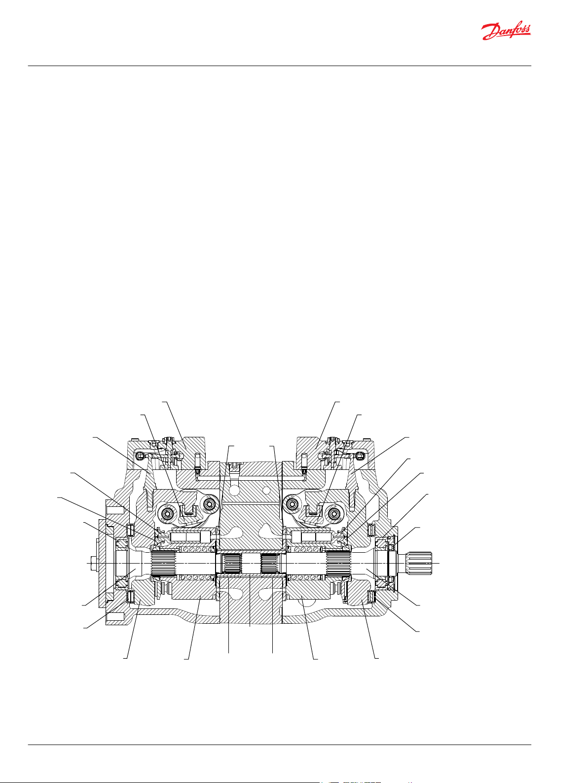
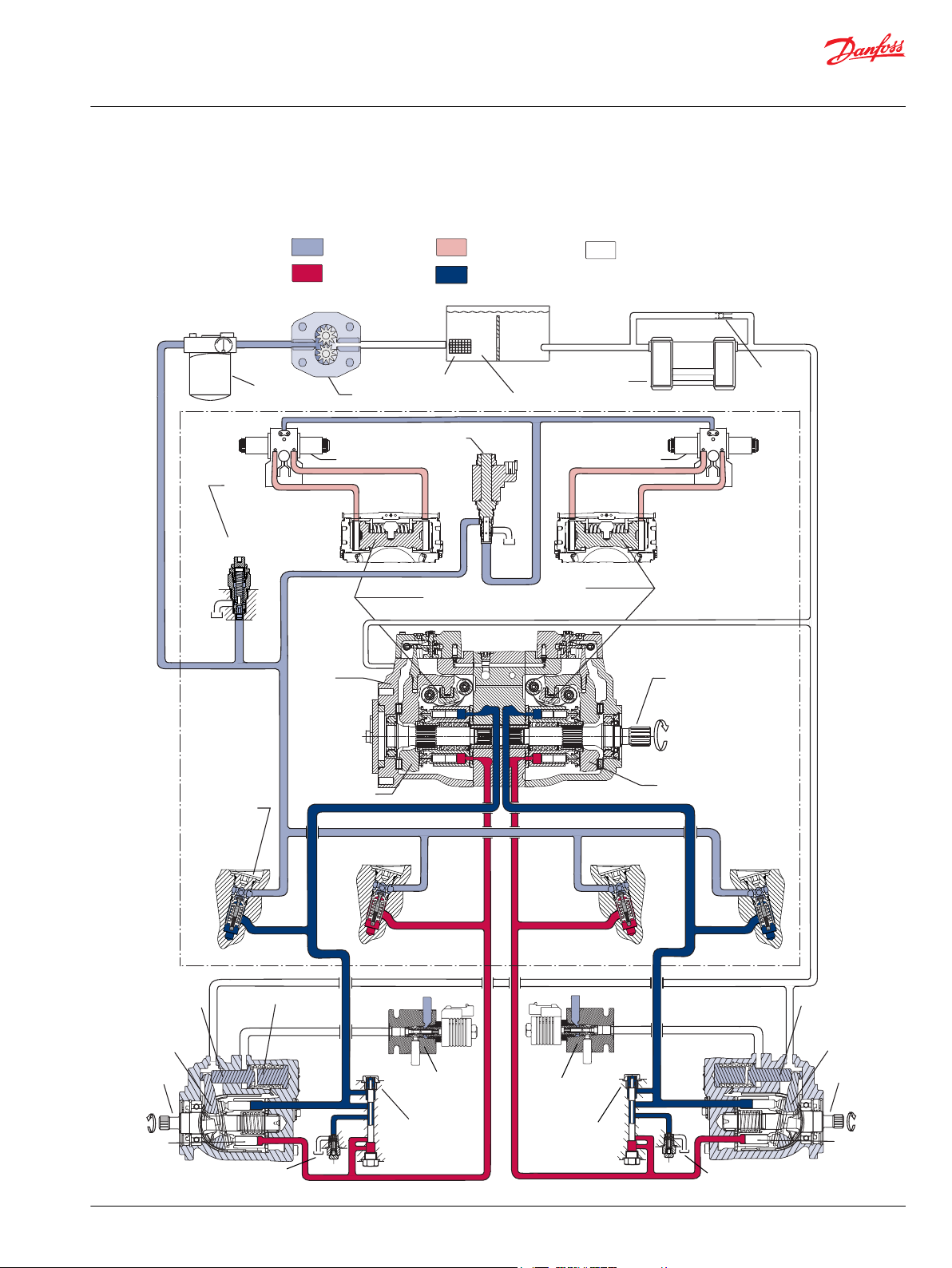
Tandem Pumps Design
Danfoss H1 tandem closed circuit piston pumps convert input torque to hydraulic power. The tandem
design powers two independent drive trains for dual-path propel applications.
The two-piece input shaft transmits rotational force to the cylinder block. A splined coupling connects
the front and rear shafts. Bearings at the front, rear, and center of the pump support the shaft. Splines
connect each shaft to a cylinder block. A lip-seal at the front end of the pump prevents leakage where the
shaft exits the pump housing. The spinning cylinder block contains nine reciprocating pistons. Each
piston has a brass slipper connected at one end by a ball joint. The block spring, ball guide, and slipper
retainer hold the slippers to the swashplate. The reciprocating movement of the pistons occurs as the
slippers slide against the inclined swashplates during rotation.
Via the valve plates, one half of each cylinder block is connected to port A or C and the other half to port
B or D. Front and rear sections have independent porting in the center section. As each piston cycles in
and out of its bore, fluid is drawn from one port and displaced to the other thereby imparting hydraulic
power into the system. A small amount of fluid is allowed to flow from the cylinder block/valve plate and
slipper/swashplate interfaces for lubrication and cooling. Case drain ports return this fluid to the
reservoir. An external charge pump (not shown) provides clean, cool fluid to makeup this lubricating flow
and to maintain minimum loop pressure.
The angle of each swashplate controls the volume and direction of fluid displaced into the system. The
servo pistons control the angle of the swashplates. Each pump control, by varying the pressure at the
servo pistons, controls each piston’s position. An electric signal to the control coils transmits the
command from the operator to the pump. Mechanical feedback of the swashplate position to the control
through the feedback pins allows for very precise displacement control and increases overall system
stability. Non-feedback control options do not use the mechanical feedback link.
Cross section view
8 | © Danfoss | December 2021 AX152886481761en-000501
Page 9
Servo Control
Cylinder
Displacement Control
Servo Control
Cylinder
Displacement Control
Reservoir
Suction
Screen
Filter
Bypass check
Heat exchanger
To Pump
Case
To Pump
Case
Variable
Displacement
Pump
Input
Shaft
Pump Swashplate
Charge Pump
Pump Swashplate
Charge
Pressure
Relief
Valve
Charge check /
HPRV valve
Control
Cutoff
Valve
System Pressure
Servo Pressure
Low Loop Pressure
Suction/Case Drain/
System Return
Charge Pressure
Cylinder
block
assembl y
Motor
swashplat e
Output
shaft
Motor
servo
piston
P106147
Loop
Flushing
Valve
To
Motor
Case
Motor
servo
piston
Motor
swashplate
Output
shaft
Cylinder
block
assembly
Displacement
limiter
Loop
Flushing
Valve
Motor
displacement
control valve
Motor
displacement
control valve
To
Motor
Case
Service Manual
H1T 045/053, 060/068 Axial Piston Tandem Pumps
Introduction
H1T pumps pictorial diagram
©
Danfoss | December 2021 AX152886481761en-000501 | 9
Page 10
P106 148E
M4
M5
M5
M4
M3
L3
MBMC
MA
MD
C
D
B
A
E
X7
C1
C2
C1
C2
CW
CW
Flow
out C
Flow
out A
M5
M4
A
MA
MD
D
B MB
MC
C
M5
M4
H1 Tandem
E
M3
ccw
flow out B flow out D
C1 C2
M14
C1C2
M14
1
2
Supply/Ground
CONTROL SOLENOID C1
Ground/Supply
1
2
Supply/Ground
Ground/Supply
CONTROL SOLENOID C2
1
2
Supply/Ground
CONTROL SOLENOID C2
Ground/Supply
1
2
Supply/Ground
Ground/Supply
CONTROL SOLENOID C1
X7
1
2
Supply/Ground
Ground/Supply
CCO SOLENOID
1
2
Supply/Ground
Ground/Supply
BRAKE SOLENOID
L1
L3
P109541
Service Manual
H1T 045/053, 060/068 Axial Piston Tandem Pumps
Introduction
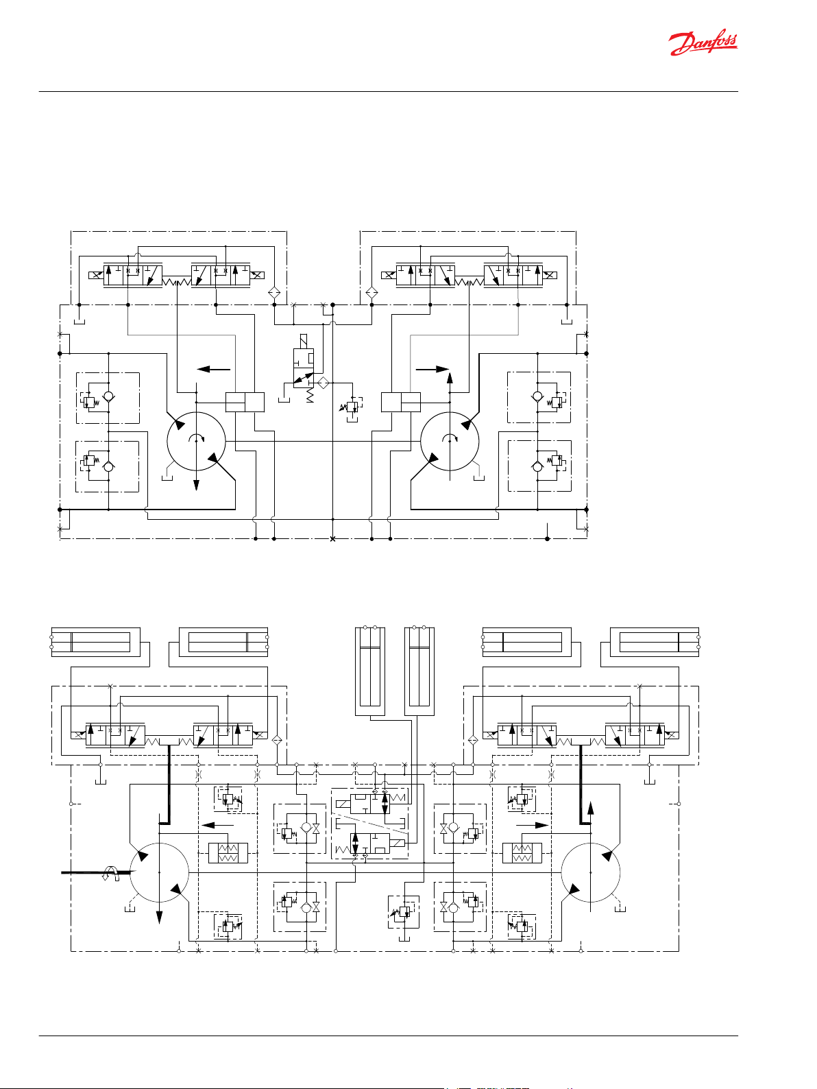
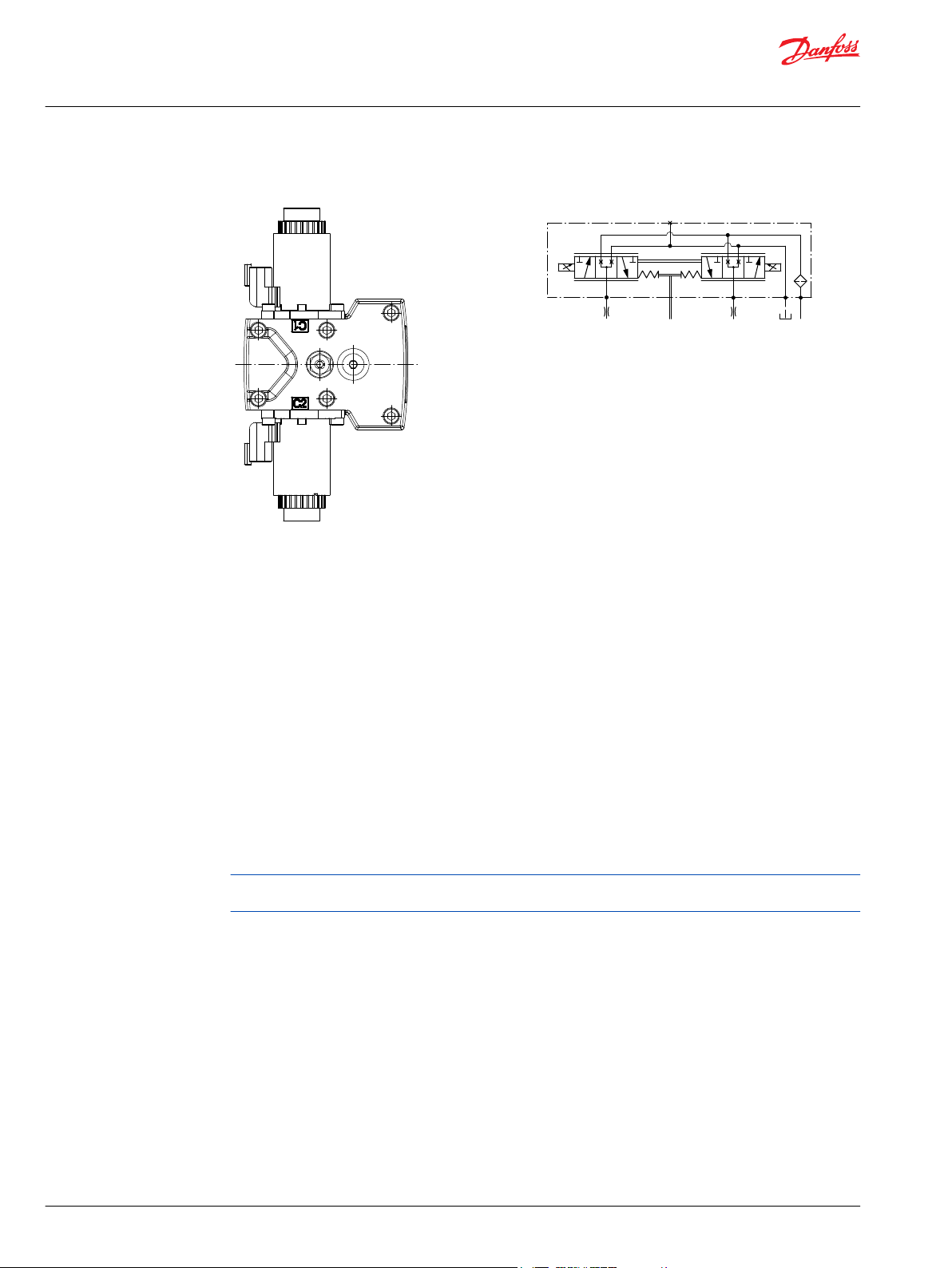
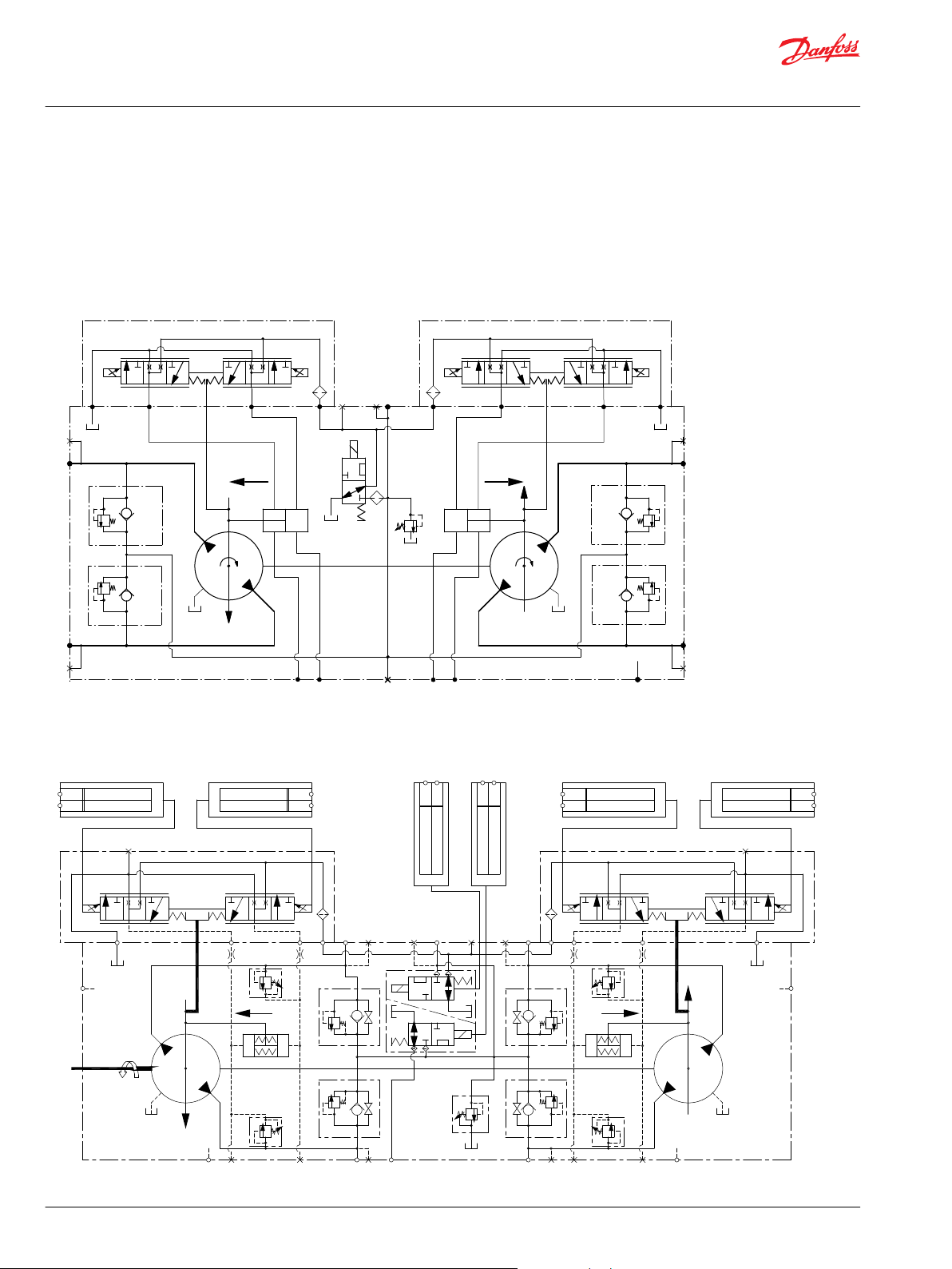
H1T Tandem Pumps Schematics
The schematics below show the function of an H1 tandem axial piston variable displacement pump with
electric displacement control (EDC) and optional control cut-off valve.
045/053 Tandem
060/068 Tandem
10 | © Danfoss | December 2021 AX152886481761en-000501
Page 11
C1
C1
C2C2
M14
M14
CW
F00B
F00A
F00B F00A
A
B
MA
E
C D
MD
MB
M3
L3
MC
M4
M5
M4
M5
PTO
X7
P003 207E
Service Manual
H1T 045/053, 060/068 Axial Piston Tandem Pumps
Introduction
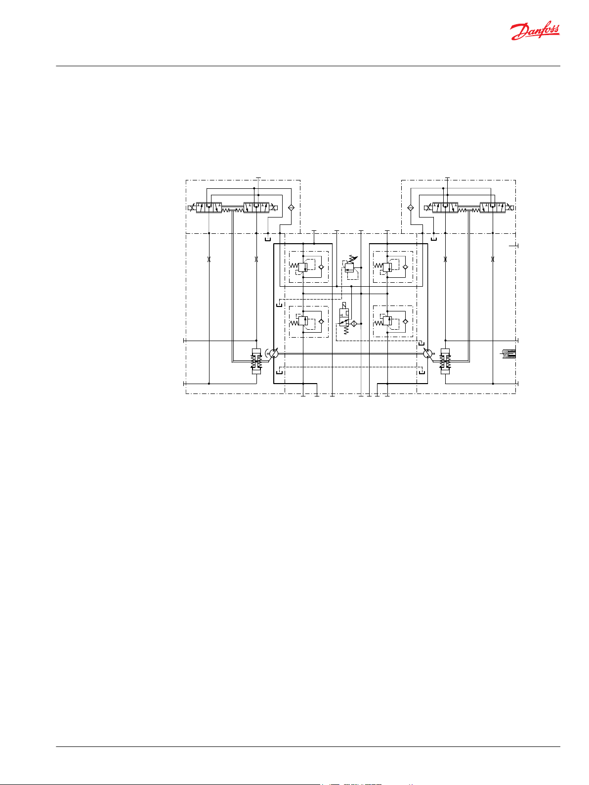
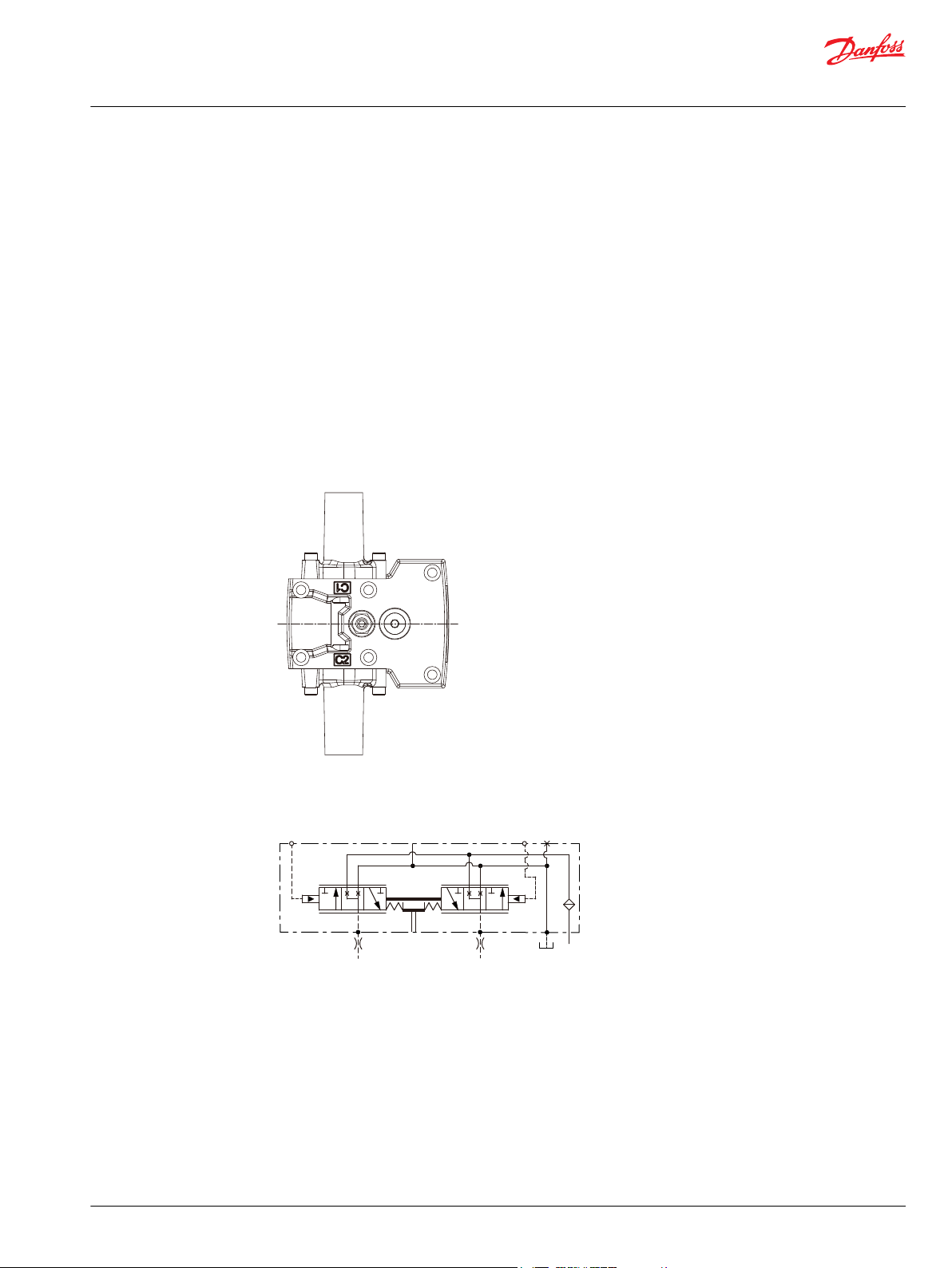
System Schematic for Tandem Pumps
The schematic below shows the function of H1T axial piston variable displacement tandem pumps with
electric displacement control (EDC).
System schematic, tandem pumps
©
Danfoss | December 2021 AX152886481761en-000501 | 11
Page 12
Service Manual
H1T 045/053, 060/068 Axial Piston Tandem Pumps
Operation
Pressure Limiter Valves
Pressure limiter valves provide system pressure protection by compensating the pump swash plate
position when the set pressure of the valve is reached. A pressure limiter is a non-dissipative (non heat
generating) pressure regulating system.
Each side of the transmission loop has a dedicated pressure limiter valve that is set independently. A
pump configured with pressure limiter must have pressure limiters on both sides of the system pressure
loop. The pump order code allows for different pressure settings to be used at each system port.
The pressure limiter setting is the maximum differential pressure between the high and low loops. When
the pressure limiter setting is reached, the valve ports oil to the low-pressure side of the servo piston. The
change in servo differential pressure rapidly reduces pump displacement. Fluid flow from the valve
continues until the resulting drop in pump displacement causes system pressure to fall below the
pressure limiter setting.
An active pressure limiter destrokes a pump to near neutral when the load is in a stalled condition. The
pump swash-plate moves in either direction necessary to regulate the system pressure, including into
stroke (overrunning) or over-center (winch payout).
The pressure limiter is optional on H1 pumps (except H1T 045/053 tandem pumps).
Pressure Limiter Sectional View
12 | © Danfoss | December 2021 AX152886481761en-000501
Page 13
P003 268
P003 269
P109187
1
2
P109188
1
2
Service Manual
H1T 045/053, 060/068 Axial Piston Tandem Pumps
Operation
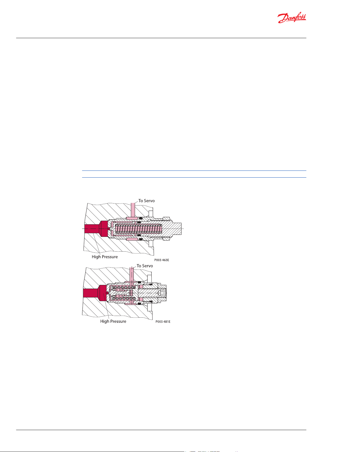
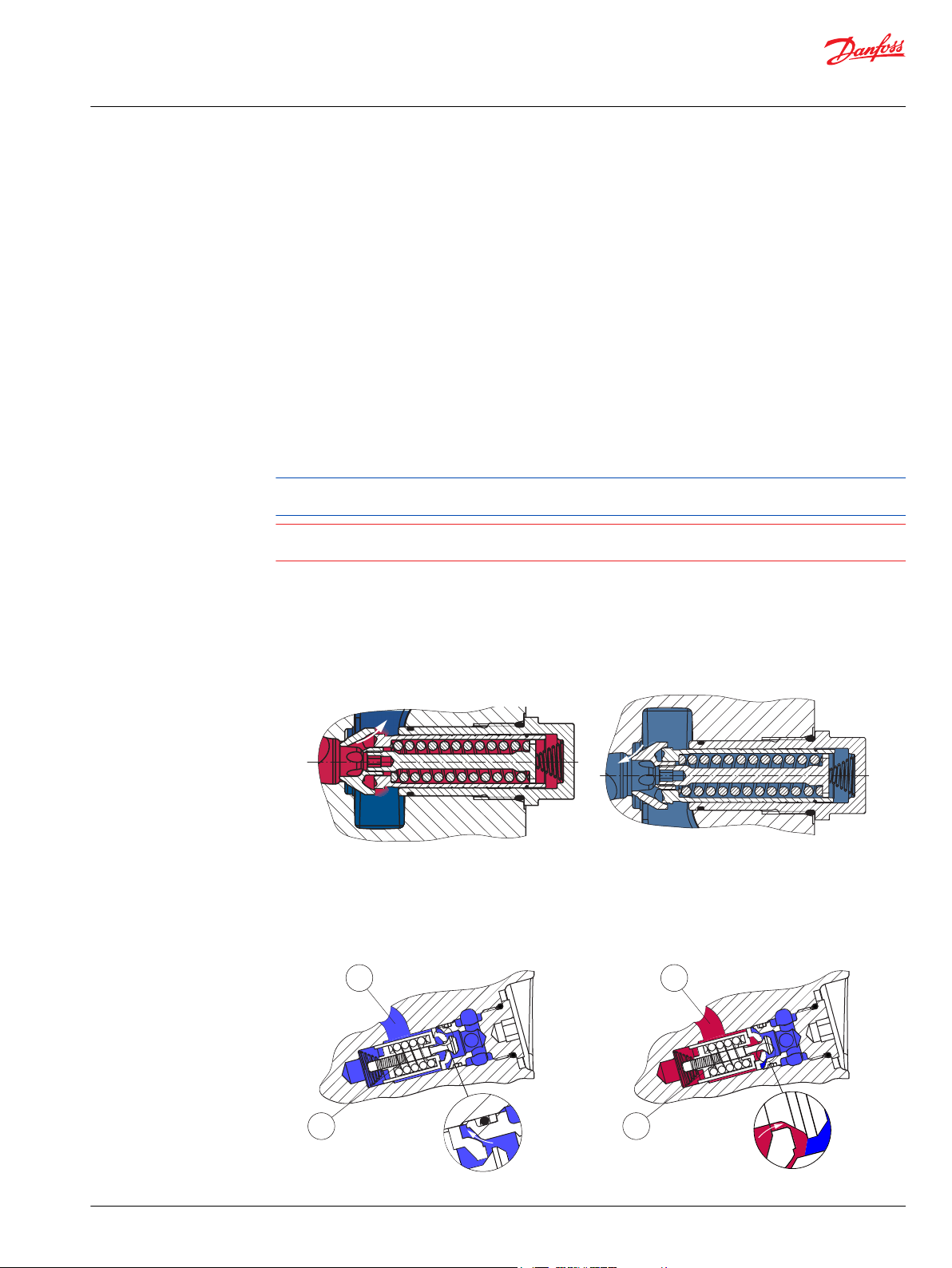
High Pressure Relief Valve (HPRV) and Charge Check Valve
All H1 pumps have a combination high pressure relief and charge check valve. The high pressure relief
function is a dissipative (heat generating) pressure control valve for the purpose of limiting excessive
system pressures. The charge check function replenishes the low pressure side of the working loop with
charge oil.
Each side of the transmission loop has a dedicated HPRV valve that is non-adjustable with a factory set
pressure. When system pressure exceeds the factory setting of the valve, oil is passed from the high
pressure system loop, into the charge gallery, and into the low pressure system loop via the charge
check.
The pump may have different pressure settings to be used at each system port. When an HPRV valve is
used in conjunction with a pressure limiter, the HPRV valve is always factory set above the setting of the
pressure limiter. The system pressure shown in the order code for pumps with only HPRV is the HPRV
setting.
The system pressure shown in the order code for pumps with pressure limiter and HPRV is a reflection of
the pressure limiter setting:
HPRVs are set at low flow condition. Any application or operating condition which leads to elevated HPRV
flow will cause a pressure rise with flow above the valve setting. Consult factory for application review.
Excessive operation of the HPRV will generate heat in the closed loop and may cause damage to the
internal components of the pump.
HPRV/Charge Check Valve Sectional View
HPRV and Charge Check Valve with Bypass Function (except 045/053)
Relief mode
Charging mode
HPRV and Charge Check Valve with Bypass Function (except H1P 045/053)
Charging mode
Relief mode
©
Danfoss | December 2021 AX152886481761en-000501 | 13
Page 14

Service Manual
H1T 045/053, 060/068 Axial Piston Tandem Pumps
Operation
1. Low pressure side of working loop
2. Charge check and HPRV
1. High pressure side of working loop
2. Charge check and HPRV
14 | © Danfoss | December 2021 AX152886481761en-000501
Page 15
Service Manual
H1T 045/053, 060/068 Axial Piston Tandem Pumps
Operation
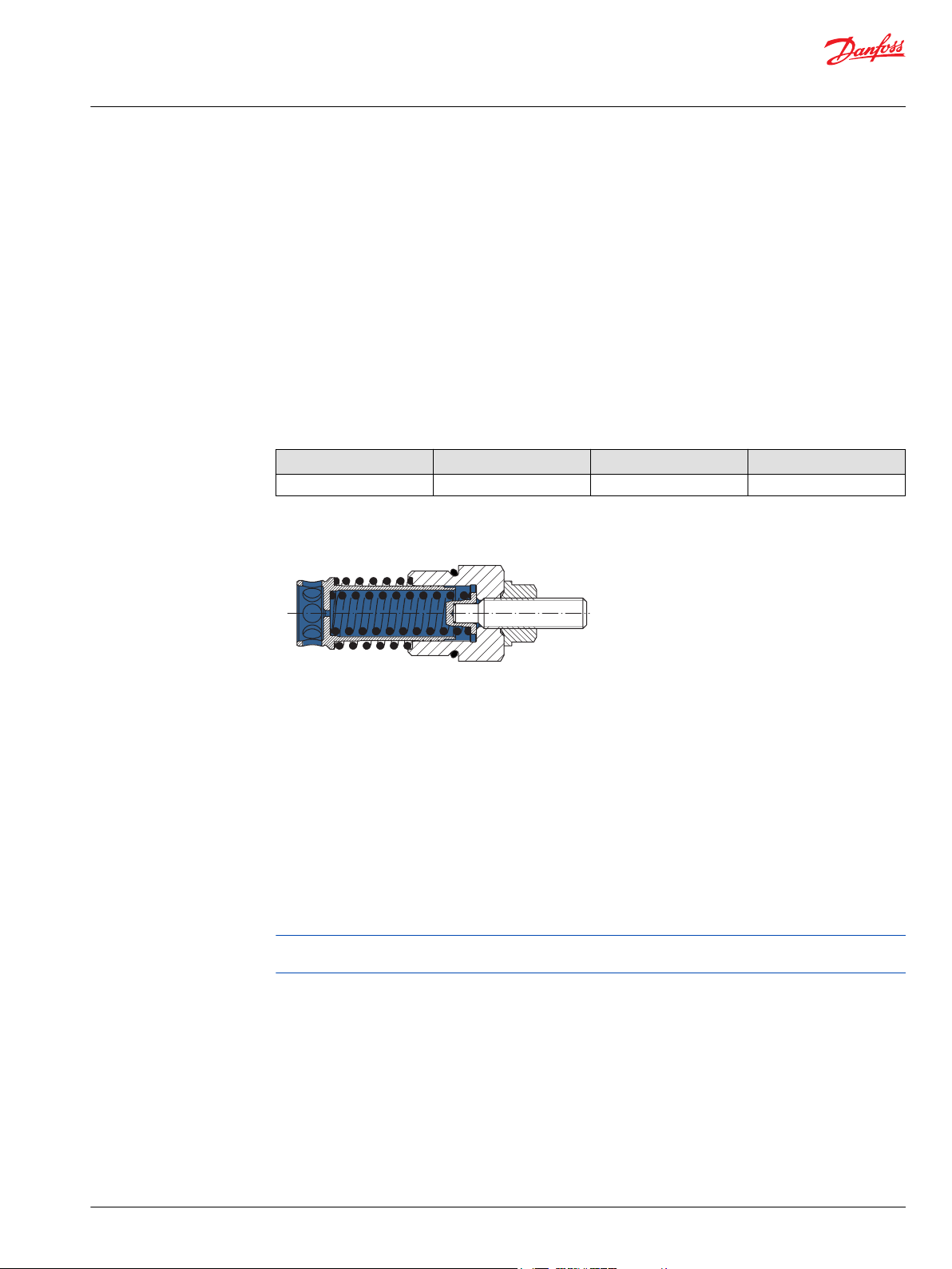
Charge Pressure Relief Valve (CPRV)
The charge pressure relief valve is a direct acting poppet valve that opens and discharges fluid to the
pump case when pressure exceeds a designated level. The charge pressure relief valve maintains charge
pressure at a designated level above case pressure.
This level is nominally set with the pump running at 1800 min-1(rpm), and with a fluid viscosity of 32
mm²/s [150 SUS]. In forward or reverse, charge pressure will be slightly lower than in neutral position. The
model code of the pump specifies the charge pressure relief valve setting. Typical charge pressure
increase from 1.2-1.5 bar per 10 l/min [17.4-21.8 psi per 2.64 US gal/min]. For external charge flow the
CPRV is set according to the table below:
Standard level setting is ∆p = 21 ± 1.1 bar [304 ± 16 psi] with the pump running at 1500 min-1(rpm) and
flow = 23.80 - 29.5 l/min [ 6.3 - 7.8 US gal/min]. Typical charge pressure increase is 2 bar per 10 l/min [29
psi per 2.64 US gal/min].
CPRV flow setting for external charge supply
Tandem 045/053 Single 045/053 Single 060—165 Single 210/250/280
30 l/min [7.9 US gal/min] 15 l/min [3.9 US gal/min] 22.7 l/min [6.0 US gal/min] 40.0 l/min [10.6 US gal/min]
Charge pressure relief valve
Electrical Displacement Control (EDC)
An EDC is a displacement (flow) control. Pump swash plate position is proportional to the input
command and therefore vehicle or load speed (excluding influence of efficiency), is dependent only on
the prime mover speed or motor displacement.
The Electrical Displacement Control (EDC) consists of a pair of proportional solenoids on each side of a
three-position, four-way porting spool. The proportional solenoid applies a force input to the spool,
which ports hydraulic pressure to either side of a double acting servo piston. Differential pressure across
the servo piston rotates the swash plate, changing the pump‘s displacement from full displacement in
one direction to full displacement in the opposite direction.
A serviceable 170 μm screen is located in the supply line immediately before the control porting spool.
Under some circumstances, such as contamination, the control spool could stick and cause the pump to
stay at some displacement.
©
Danfoss | December 2021 AX152886481761en-000501 | 15
Page 16
P003 191
Feedback from
Swash plate
PTF00B
M14
C1 C2
F00A
P003 478E
Service Manual
H1T 045/053, 060/068 Axial Piston Tandem Pumps
Operation
Electrical Displacement Control
EDC schematic, feedback from swash plate
EDC Operation
H1 EDC’s are current driven controls requiring a Pulse Width Modulated (PWM) signal. Pulse width
modulation allows more precise control of current to the solenoids.
The PWM signal causes the solenoid pin to push against the porting spool, which pressurizes one end of
the servo piston, while draining the other. Pressure differential across the servo piston moves the
swashplate.
A swashplate feedback link, opposing control links, and a linear spring provide swashplate position force
feedback to the solenoid. The control system reaches equilibrium when the position of the swashplate
spring feedback force exactly balances the input command solenoid force from the operator. As
hydraulic pressures in the operating loop change with load, the control assembly and servo/swashplate
system work constantly to maintain the commanded position of the swashplate.
The EDC incorporates a positive neutral deadband as a result of the control spool porting, preloads from
the servo piston assembly, and the linear control spring. Once the neutral threshold current is reached,
the swashplate is positioned directly proportional to the control current. To minimize the effect of the
control neutral deadband, we recommend the transmission controller or operator input device
incorporate a jump up current to offset a portion of the neutral deadband.
The neutral position of the control spool does provide a positive preload pressure to each end of the
servo piston assembly.
When the control input signal is either lost or removed, or if there is a loss of charge pressure, the springloaded servo piston will automatically return the pump to the neutral position.
16 | © Danfoss | December 2021 AX152886481761en-000501
Page 17
P400520
P400519
X1
F00B
F00A
Feedback from
Swashplate
T P
X2M14
Service Manual
H1T 045/053, 060/068 Axial Piston Tandem Pumps
Operation
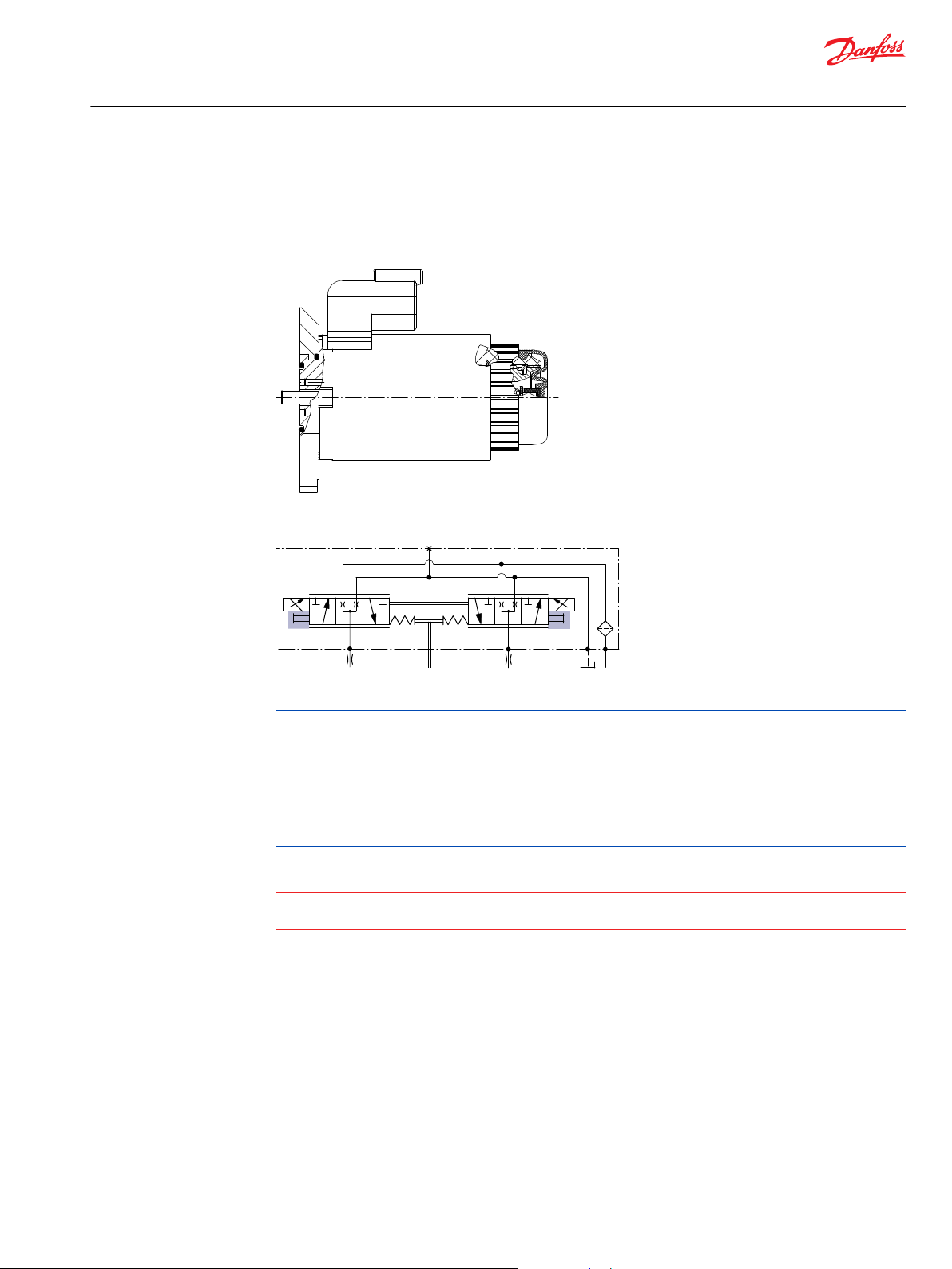
Hydraulic Displacement Control (HDC)
HDC principle
An HDC is a Hydraulic Displacement Control. Pump swashplate position is proportional to the input
command and therefore vehicle speed or load speed (excluding influence of efficiency), is dependent
only on the prime mover speed or motor displacement.
The HDC control uses a hydraulic input signal to operate a porting spool, which ports hydraulic pressure
to either side of a double acting servo piston. The hydraulic signal applies a force input to the spool
which ports hydraulic pressure to either side of a double acting servo piston. Differential pressure across
the servo piston rotates the swashplate, changing the pump’s displacement from full displacement in
one direction to full displacement in the opposite direction. Under some circumstances, such as
contamination, the porting spool could stick and cause the pump to stay at some displacement.
A serviceable 175 μm screen is located in the supply line immediately before the control porting spool.
HDC control
HDC schematic
HDC operation
HDC’s are hydraulically driven control which ports hydraulic pressure to either side of a porting spool,
which pressurizes one end of the servo piston, while draining the other end to case. Pressure differential
across the servo piston moves the swashplate.
A swashplate feedback link, opposing control linkage, and a linear spring provide swashplate position
force feedback to the hydraulic pressure. As hydraulic pressures in the operating loop change with load,
the control assembly and servo/swashplate system work constantly to maintain the commanded position
of the swashplate.
©
Danfoss | December 2021 AX152886481761en-000501 | 17
Page 18
"0"
Signal pressure
Displacement
100 %
a b
-b -a
100 %
P102 031E
Service Manual
H1T 045/053, 060/068 Axial Piston Tandem Pumps
Operation
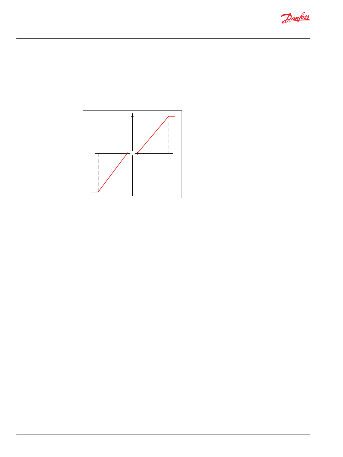
The HDC incorporates a positive neutral dead band as a result of the control spool porting, preloads from
the servo piston assembly, and the linear control spring. Once the neutral threshold point is reached, the
swashplate is positioned directly proportional to the control pressure.
When the control input is either lost or removed, or if there is a loss of charge pressure, the spring loaded
servo piston will automatically return the pump to the neutral position.
Pump displacement vs signal pressure
18 | © Danfoss | December 2021 AX152886481761en-000501
Page 19
P003 204
PTF00B
M14
C2
C1
F00A
W
Service Manual
H1T 045/053, 060/068 Axial Piston Tandem Pumps
Operation
Manual Override (MOR)
All controls are available with a manual override functionality, either as a standard or as an option for
temporary actuation of the control to aid in diagnostics.
Control with manual override
MOR schematic (EDC control shown)
Feedback from swash plate.
The MOR plunger has a 4 mm diameter and must be manually depressed to be engaged. Depressing the
plunger mechanically moves the control spool which allows the pump to go on stroke. The MOR should
be engaged anticipating a full stroke response from the pump.
An o-ring seal is used to seal the MOR plunger where initial actuation of the function will require a force
of 45 N to engage the plunger. Additional actuation typically require less force to engage the MOR
plunger.
Proportional control of the pump using the MOR should not be expected.
Warning
Unintended MOR operation will cause the pump to go into stroke; example: vehicle lifted off the ground.
The vehicle or device must always be in a safe condition when using the MOR function.
Refer to control flow table for the relationship of solenoid to direction of flow.
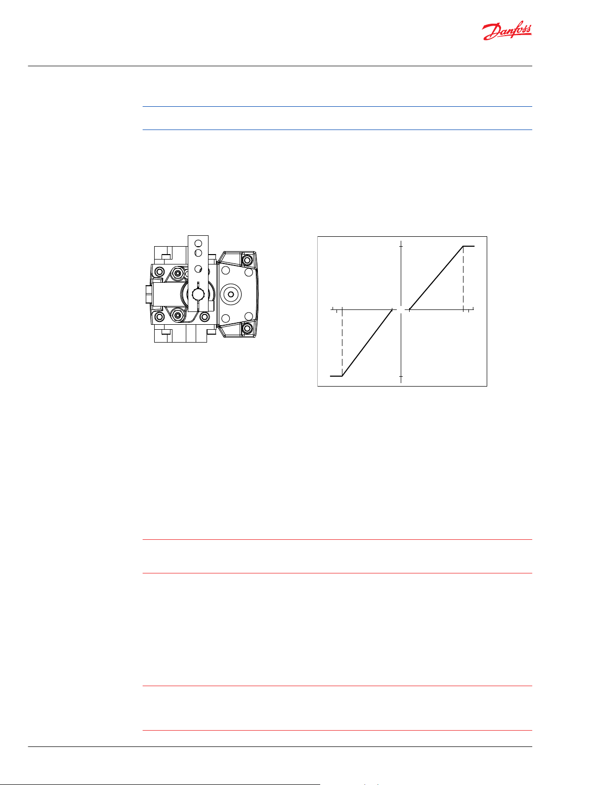
Manual Displacement Control (MDC)
A Manual proportional Displacement Control (MDC) consists of a handle on top of a rotary input shaft.
The shaft provides an eccentric connection to a feedback link. This link is connected on its one end with a
porting spool. On its other end the link is connected the pumps swashplate.
This design provides a travel feedback without spring. When turning the shaft the spool moves thus
providing hydraulic pressure to either side of a double acting servo piston of the pump.
Differential pressure across the servo piston rotates the swash plate, changing the pump’s displacement.
Simultaneously the swashplate movement is fed back to the control spool providing proportionality
between shaft rotation on the control and swash-plate rotation. The MDC changes the pump
displacement between no flow and full flow into opposite directions.
©
Danfoss | December 2021 AX152886481761en-000501 | 19
Page 20
"0"
Lever rotation
"A"
Displacement
100 %
a
-a
100 %
"B"
-b
-d
b
c
d
-c
P301 752
C
Service Manual
H1T 045/053, 060/068 Axial Piston Tandem Pumps
Operation
Under some circumstances, such as contamination, the control spool could stick and cause the pump to
stay at some displacement.
For the MDC with CCO option the brake port (X7) provides charge pressure when the coil is energized to
activate static function such as a brake release. The X7 port must not be used for any continuous oil
consumption.
The MDC is sealed by means of a static O-ring between the actuation system and the control block. Its
shaft is sealed by means of a special O-ring which is applied for low friction. The special O-ring is
protected from dust, water and aggressive liquids or gases by means of a special lip seal.
Manual Displacement Control Pump displacement vs. control lever rotation
Deadband on B side: a = 3° ±1°
Maximum pump stroke: b = 30° +2/-1°
Required customer end stop: c = 36° ±3°
Internal end stop: d = 40°
MDC operation
The MDC provides a mechanical dead-band required to overcome the tolerances in the mechanical
actuation. The MDC contains an internal end stop to prevent turning the handle into any inappropriate
position.
The MDC provides a permanent restoring moment appropriate for turning the MDC input shaft back to
neutral position only. This is required to take the backlash out of the mechanical connections between
the Bowden cable and the control.
High case pressure may cause excessive wear and the NSS to indicate that the control is not in neutral
position. In addition, if the case pressure exceeds 5 bar there is a risk of an insufficient restoring moment.
The MDC is designed for a maximum case pressure of 5 bar and a rated case pressure of 3 bar.
Customers must install some support to limit the setting range of their Bowden cable to avoid an
•
overload of the MDC.
Customers can apply their own handle design but they must care about a robust clamping
•
connection between their handle and the control shaft and avoid overload of the shaft.
Customers can connect two MDC’s on a tandem unit in such a way that the actuation force will be
•
transferred from the pilot control to the second control. The kinematic of the linkages must ensure
that either control shaft is protected from torque overload.
Caution
Using the internal spring force on the input shaft is not an appropriate way to return the customer
connection linkage to neutral, or to force a Bowden cable or a joystick back to neutral position. It is not
applicable for any limitation of the Bowden cable stroke, except the applied torque to the shaft will never
exceed 20 N•m.
20 | © Danfoss | December 2021 AX152886481761en-000501
Page 21
C
P005 702
M14
M5
M4
M3
Service Manual
H1T 045/053, 060/068 Axial Piston Tandem Pumps
Operation
MDC Torque
Description Value
Torque required to move handle to maximum displacement 1.4 N•m [12.39 lbf•in ]
Torque required to hold handle at given displacement 0.6 N•m [5.31 lbf•in]
Maximum allowable input torque 20 N•m [177 lbf•in]
Caution
Volumetric efficiencies of the system will have impacts on the start and end input commands.
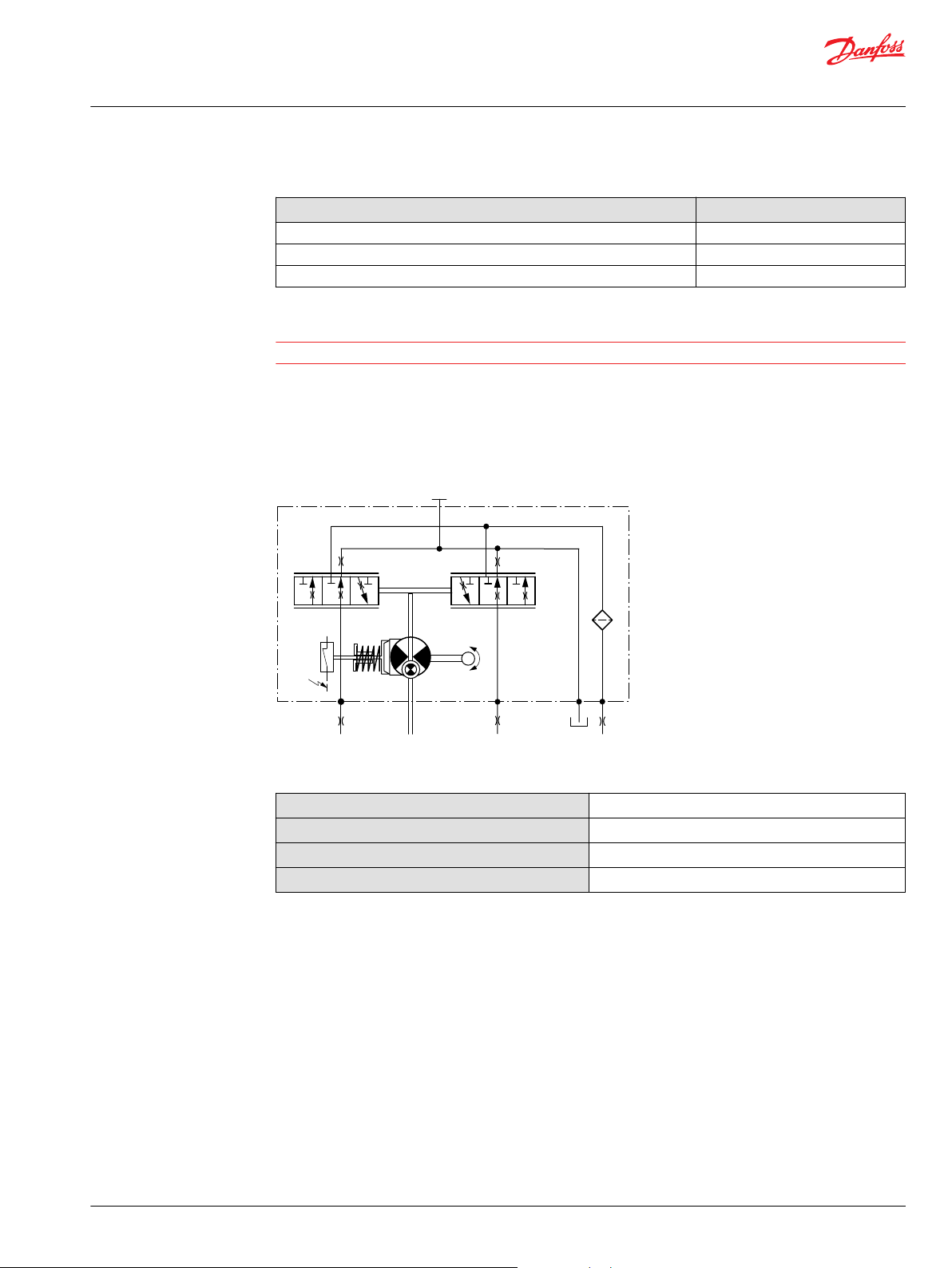
Neutral start switch (NSS)
The Neutral Start Switch (NSS) contains an electrical switch that provides a signal of whether the control
is in neutral. The signal in neutral is Normally Closed (NC).
Neutral start switch schematic
Neutral start switch data
Max. continuous current with switching
Max. continuous current without switching
Max. voltage
Electrical protection class
8.4 A
20 A
36 V
DC
IP67 / IP69K with mating connector
Case Gauge Port M14
The drain port should be used when the control is mounted on the unit’s bottom side to flush residual
contamination out of the control.
Control-Cut-Off (CCO) and Brake Release Valves
The H1 tandem pumps offer an optional Control-Cut-Off valve integrated into the pump center section
and a separate brake release valve allowing the controls to be activated before activating any auxiliary
functions.
The CCO valve shunts charge pressure from the pump controls allowing the servo springs to de-stroke
both pumps. The valve is normally open for fail-safe operation. The solenoid must be energized for the
pump to operate. When the machine control circuits energize the CCO solenoid, it connects charge
supply from the charge gallery to the pump controls.
©
Danfoss | December 2021 AX152886481761en-000501 | 21
Page 22
P106 148E
M4
M5
M5
M4
M3
L3
MBMC
MA
MD
C
D
B
A
E
X7
C1
C2
C1
C2
CW
CW
Flow
out C
Flow
out A
M5
M4
A
MA
MD
D
B MB
MC
C
M5
M4
H1 Tandem
E
M3
ccw
flow out B flow out D
C1 C2
M14
C1C2
M14
1
2
Supply/Ground
CONTROL SOLENOID C1
Ground/Supply
1
2
Supply/Ground
Ground/Supply
CONTROL SOLENOID C2
1
2
Supply/Ground
CONTROL SOLENOID C2
Ground/Supply
1
2
Supply/Ground
Ground/Supply
CONTROL SOLENOID C1
X7
1
2
Supply/Ground
Ground/Supply
CCO SOLENOID
1
2
Supply/Ground
Ground/Supply
BRAKE SOLENOID
L1
L3
P109541
Service Manual
H1T 045/053, 060/068 Axial Piston Tandem Pumps
Operation
The 045/053 tandem also supplies charge pressure to the port X7 for auxiliary operation of devices such
as spring applied/pressure released brakes. The control cut off valve also shunts pressure away from port
X7.
The 060/068 tandem offers a separate brake release valve that operates independently of the CCO valve
allowing the controls to be activated before activating any auxiliary functions. When the 60/68 brake
valve is deactivated the X7 port shunts to case.
045/053 Tandem
060/068 Tandem
22 | © Danfoss | December 2021 AX152886481761en-000501
Page 23
1 2
Service Manual
H1T 045/053, 060/068 Axial Piston Tandem Pumps
Operation
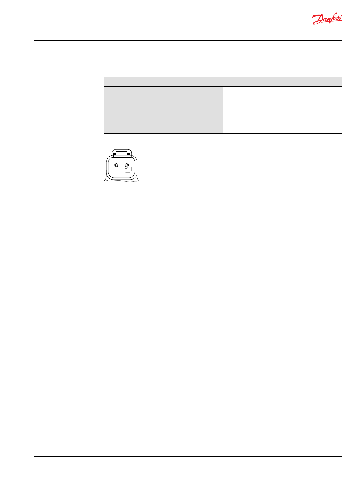
Solenoid data
Description 12 V 24 V
Minimum supply voltage
Maximum supply voltage (continuous)
IP Rating IEC 60 529
DIN 40 050, part 9
Pin connector
For additional information, please contact Danfoss.
9 V
DC
16 V
DC
IP 67
IP 69K with mating connector
any order
18 V
32 V
DC
DC
©
Danfoss | December 2021 AX152886481761en-000501 | 23
Page 24

W
Service Manual
H1T 045/053, 060/068 Axial Piston Tandem Pumps
Operating Parameters
Input Speed
Minimum
speed
Rated speed is the highest input speed recommended at full power condition. Operating at or
Maximum
speed
During hydraulic braking and downhill conditions, the prime mover must be capable of providing
sufficient braking torque in order to avoid pump over speed. This is especially important to consider for
turbo-charged and Tier 4 engines.
For more information please see Pressure and Speed Limits, BC152886484313, when determining speed
limits for a particular application.
Independent Braking System
is the lowest input speed recommended during engine idle condition. Operating below
minimum speed limits the pump’s ability to maintain adequate flow for lubrication and
power transmission.
below this speed should yield satisfactory product life.
Operating conditions between rated and maximum speed should be restricted to less
than full power and to limited periods of time.
is the highest operating speed permitted. Exceeding maximum speed reduces product
life and can cause loss of hydrostatic power and braking capacity. For most drive
systems, maximum unit speed occurs during downhill braking or negative power
conditions.
Warning
Never exceed the maximum speed limit under any operating conditions.
System Pressure
Unintended vehicle or machine movement hazard. Exceeding maximum speed may cause a loss of
hydrostatic drive line power and braking capacity.
Machine manufacturer is responsible to provide a braking system, redundant to the hydrostatic
transmission, sufficient to stop and hold the vehicle or machine in the event of hydrostatic drive power
loss. The braking system must also be sufficient to hold the machine in place when full power is applied.
Hydraulic unit life depends on the speed and normal operating — or weighted average — pressure that
can only be determined from a duty cycle analysis.
System pressure is the differential pressure between high pressure system ports. It is the dominant
operating variable affecting hydraulic unit life. High system pressure, which results
from high load, reduces expected life.
Application
pressure
Maximum
working
pressure
is the high pressure relief or pressure limiter setting normally defined within the
order code of the pump. This is the applied system pressure at which the drive line
generates the maximum calculated pull or torque in the application.
is the highest recommended application pressure and is not intended to be a
continuous pressure. Propel systems with application pressures at, or below this
pressure should yield satisfactory unit life given proper component sizing.
Application pressures above maximum working pressure will only be considered
with duty cycle analysis and factory approval.
Pressure spikes are normal and must be considered when reviewing maximum
working pressure.
24 | © Danfoss | December 2021 AX152886481761en-000501
Page 25

Service Manual
H1T 045/053, 060/068 Axial Piston Tandem Pumps
Operating Parameters
Maximum
pressure
Minimum low
loop pressure
is the highest intermittent pressure allowed under any circumstances. Applications
with applied pressures between rated and maximum require factory approval with
complete application, duty cycle, and life expectancy analysis.
must be maintained under all operating conditions to avoid cavitation.
All pressure limits are differential pressures referenced to low loop (charge) pressure.
Subtract low loop pressure from gauge readings to compute the differential.
©
Danfoss | December 2021 AX152886481761en-000501 | 25
Page 26

Service Manual
H1T 045/053, 060/068 Axial Piston Tandem Pumps
Operating Parameters
Servo Pressure
Servo pressure is the pressure in the servo system needed to position and hold the pump on stroke. It
depends on system pressure and speed. At minimum servo pressure the pump will run at reduced stroke
depending on speed and pressure.
Minimum servo pressure at corner power holds the pump on full stroke at max speed and max
pressure.
Maximum servo pressure is the highest pressure typically given by the charge pressure setting.
Charge Pressure
An internal charge relief valve regulates charge pressure. Charge pressure supplies the control with
pressure to operate the swashplate and to maintain a minimum pressure in the low side of the
transmission loop.
The charge pressure setting listed in the order code is the set pressure of the charge relief valve with the
pump in neutral, operating at 1800 min-1 (rpm), and with a fluid viscosity of 32 mm2/s [150 SUS].
Pumps configured with no charge pump (external charge supply) are set with a charge flow of 30 l/min
[7.93 US gal/min] and a fluid viscosity of 32 mm2/s [150 SUS].
The charge pressure setting is referenced to case pressure. Charge pressure is the differential pressure
above case pressure.
Charge Pump Inlet Pressure
Case Pressure
Minimum
charge
pressure
Maximum
charge
pressure
At normal operating temperature charge inlet pressure must not fall below rated charge inlet pressure
(vacuum).
Minimum charge inlet
pressure
Maximum charge inlet
pressure
Under normal operating conditions, the rated case pressure must not be exceeded. During cold start case
pressure must be kept below maximum intermittent case pressure. Size drain plumbing accordingly.
The auxiliary pad cavity of axial pumps configured without integral charge pumps is referenced to case
pressure. Units with integral charge pumps have auxiliary mounting pad cavities referenced to charge
inlet (vacuum).
is the lowest pressure allowed to maintain a safe working condition in the low side of
the loop. Minimum control pressure requirements are a function of speed, pressure,
and swashplate angle, and may be higher than the minimum charge pressure shown
in the Operating parameters tables.
is the highest charge pressure allowed by the charge relief adjustment, and which
provides normal component life. Elevated charge pressure can be used as a
secondary means to reduce the swashplate response time.
is only allowed at cold start conditions. In some applications it is
recommended to warm up the fluid (e.g. in the tank) before starting the
engine and then run the engine at limited speed.
may be applied continuously.
Possible component damage or leakage.
Operation with case pressure in excess of stated limits may damage seals, gaskets, and/or housings,
causing external leakage. Performance may also be affected since charge and system pressure are
additive to case pressure.
26 | © Danfoss | December 2021 AX152886481761en-000501
Page 27

C
Service Manual
H1T 045/053, 060/068 Axial Piston Tandem Pumps
Operating Parameters
External Shaft Seal Pressure
In certain applications the input shaft seal may be exposed to external pressure. In order to prevent
damage to the shaft seal the maximum differential pressure from external sources must not exceed 0.4
bar (5.8 psi) over pump case pressure.
The case pressure limits of the pump must also be followed to ensure the shaft seal is not damaged.
Caution
Regardless of the differential pressure across the shaft seal, the shaft seal has been known to pump oil
from the external source (e. g. gear box) into the pump case.
Temperature
The high temperature limits apply at the hottest point in the transmission, which is normally the motor
case drain. The system should generally be run at or below the quoted rated temperature.
The maximum intermittent temperature is based on material properties and should never be
exceeded.
Cold oil will generally not affect the durability of the transmission components, but it may affect the
ability of oil to flow and transmit power; therefore temperatures should remain 16 °C [30 °F] above the
pour point of the hydraulic fluid.
The minimum temperature relates to the physical properties of component materials.
Size heat exchangers to keep the fluid within these limits. Danfoss recommends testing to verify that
these temperature limits are not exceeded.
Viscosity
For maximum efficiency and bearing life, ensure the fluid viscosity remains in the recommended range.
The minimum viscosity should be encountered only during brief occasions of maximum ambient
temperature and severe duty cycle operation.
The maximum viscosity should be encountered only at cold start.
©
Danfoss | December 2021 AX152886481761en-000501 | 27
Page 28

Service Manual
H1T 045/053, 060/068 Axial Piston Tandem Pumps
Technical Specifications
H1 Pumps General Specification
Axial piston closed circuit variable displacement pumps of cradle swash-plate design with clockwise or
counterclockwise direction of rotation.
Pipe connections
•
Main pressure ports: ISO split flange boss
•
Main pressure ports H1P 045/053: SAE straight thread O-ring boss
•
Main pressure ports H1P 060/068: ISO split flange boss
•
Remaining ports: SAE straight thread O-ring boss
Recommended installation position
Pump installation position is discretionary, however the recommended control position is on the top or
at the side with the top position preferred. If the pump is installed with the control at the bottom,
flushing flow must be provided through port M14 located on the EDC, FNR and NFPE control.
Vertical input shaft installation is acceptable. If input shaft is at the top, 1 bar case pressure must be
maintained during operation. The housing must always be filled with hydraulic fluid. Recommended
mounting for a multiple pump stack is to arrange the highest power flow towards the input source.
Consult Danfoss for nonconformance to these guidelines.
Auxiliary cavity pressure
Auxiliary cavity pressure will be inlet pressure with internal charge pump or case pressure with external
charge supply. For reference see Operating Parameters. Please verify mating pump shaft seal capability.
Technical Data for H1 Tandem Pumps
Technical Data
Feature Unit 045 053 060 068
Displacement cm3 [in3] 45.0 [2.75] 53.8 [3.28] 60.4 [3.69] 68.0 [4.15]
Flow at rated (continuous) speed
Torque at maximum displacement
(theoretical)
Mass moment of inertia of rotating
components
Mass (weight dry, without charge
pump or auxiliary flange)
Oil volume l [US gal] 2.3 [0.61] 2.3 [0.61] 4.2 [1.1] 4.2 [1.1]
*
Applies for each rotating group.
Physical properties
Description 045/053 060/068
Mounting flange per ISO 3019-1 Flange 101-2 (SAE B), special bolt Flange 127-4 (SAE C)
Input shaft outer diameter, splines
per ISO 3019-1
*
l/min
[US gal/min]
N•m/bar
[lb•in/1000 psi]
2
kg•m
[slug•ft2]
kg [lb] 65 [143] 65 [143] 96.2 [212] 96.2 [212]
Ø25 mm - 4 (SAE B-B, 15 teeth)
•
Ø32 mm - 4 (SAE-C, 14 teeth)
•
Ø31 mm - 4 (19 teeth)
•
153 [40] 183 [48] 210 [55.5] 238 [62.8]
0.8 [488] 0.9
0.0077
[0.00568]
[549]0.007
8 [0.00575]
0.0078
[0.00575
•
•
Ø32 mm - 4 (SAE C, 14 teeth)
Ø35 mm - 4 (SAE C, 21 teeth)
0.96 [590] 1.08 [610]
0.0143
[0.01055]
0.0143
[0.01052]
28 | © Danfoss | December 2021 AX152886481761en-000501
Page 29

Service Manual
H1T 045/053, 060/068 Axial Piston Tandem Pumps
Technical Specifications
Physical properties (continued)
Description 045/053 060/068
Auxiliary mounting flange with
metric fasteners, shaft outer diameter
and splines per ISO 3019-1
Charge inlet port per ISO 11926-1
Main port configuration ISO 11926-1: 1 5∕16 -12 (SAE O-ring
Other ports SAE O-ring boss
Customer interface threads Metric fasteners
Operating parameters for H1 Tandem Pumps
Input Speed (at minimum charge/control pressure)
Description Size 045/053 Size 060/068
Minimum for external charge supply
Rated 3400 min-1 (rpm) 3500 min-1 (rpm)
Maximum 3500 min-1 (rpm) 4000 min-1 (rpm)
1)
Full performance (pressure and displacement) possible at minimum charge and control pressure supply.
Flange 82–2 outer dia:
Ø16 mm - 4 (SAE A, 9 teeth)
•
Ø19 mm - 4 (SAE A, 11 teeth)
•
Flange 101–2 outer dia:
Ø22 mm - 4 (SAE B, 13 teeth)
•
Ø25 mm - 4 (SAE B-B, 15 teeth)
•
7
∕8 -14 (SAE O-ring boss) 1 1∕16 -14 (SAE O-ring boss)
boss)
1)
500 min-1 (rpm) 500 min-1 (rpm)
Flange 101–2 outer dia:
Ø22 mm - 4 (SAE B, 13 teeth)
•
Ø25 mm - 4 (SAE B-B, 15 teeth)
•
ISO 6162: M12 x 1.75 (Split flange)
System pressure
Description Size 045 Size 053 Size 060 Size 068
System pressure Max. working 420 bar [6092 psi] 380 bar [5511 psi] 420 bar [6090 psi] 380 bar [5510 psi]
Maximum (peak) 450 bar [6527 psi] 400 bar [5802 psi] 450 bar [6525 psi] 400 bar [5800 psi]
Max. low loop 45 bar [653 psi] 45 bar [650 psi]
Min. low loop 10 bar [145 psi] 10 bar [145 psi]
Control pressure Min. at corner
power (EDC,
MDC, FNR)
Maximum 40 bar [580 psi] 40 bar [580 psi]
21.5 bar [312 psi] 18.5 bar [270 psi]
Other pressure type for all tandem pumps
Description 045–068
Charge pressure Minimum without CCO valve 14.5 bar [210 psi]
Minimum with CCO valve 18 bar [265 psi]
Maximum 34 bar [493 psi]
Case pressure Rated 3.0 bar [44.0 psi]
Maximum 5.0 bar [73.0 psi]
Lip seal external Maximum 0.4 bar [5.8 psi]
©
Danfoss | December 2021 AX152886481761en-000501 | 29
Page 30

Service Manual
H1T 045/053, 060/068 Axial Piston Tandem Pumps
Technical Specifications
Fluid Specification
Viscosity
Intermittent
Minimum
Recommended range
Maximum
1)
Intermittent = Short term t < 1 min per incident and not exceeding 2 % of duty cycle based load-life.
Temperature
Minimum
Rated
Recommended range
Maximum Intermittent
1)
Cold start = Short term t > 3 min, p ≤ 50 bar [725 psi], n ≤ 1000 min-1 (rpm).
2)
At the hottest point, normally case drain port.
1)
1)
2)
5 mm2/s [42 SUS]
7 mm2/s [49 SUS]
12 – 80 mm2/s [66 – 370 SUS]
1600 mm2/s [7500 SUS]
-40°C [-40°F]
104°C [220°F]
60 – 85°C [140 – 185°F]
115°C [240°F]
30 | © Danfoss | December 2021 AX152886481761en-000501
Page 31

C
Service Manual
H1T 045/053, 060/068 Axial Piston Tandem Pumps
Fluid and Filter Maintenance Recommendations
To ensure optimum life perform regular maintenance of the fluid and filter. Contaminated fluid is the
main cause of unit failure. Take care to maintain fluid cleanliness when servicing.
Check the reservoir daily for proper fluid level, the presence of water, and rancid fluid odor. Fluid
•
contaminated by water may appear cloudy or milky or free water may settle in the bottom of the
reservoir. Rancid odor indicates the fluid has been exposed to excessive heat. Change the fluid and
correct the problem immediately if these conditions occur.
Inspect vehicle for leaks daily. Change the fluid and filter per the vehicle/machine manufacturer's
•
recommendations or at intervals shown in the table. We recommend first fluid change at 500 hours.
Fluid and filter change interval
Reservoir type Max oil change interval
Sealed 2000 hours
Breather 500 hours
High temperatures and pressures will result in accelerated fluid aging. More frequent fluid changes
may be required.
Change the fluid more frequently if it becomes contaminated with foreign matter (dirt, water, grease,
•
etc.) or if the fluid is subjected to temperature levels greater than the recommended maximum.
Dispose of used hydraulic fluid properly. Never reuse hydraulic fluid.
•
Change filters with the fluid or when the filter indicator shows it's necessary.
•
Replace all fluid lost during filter change.
•
Caution
Hydraulic fluid contains hazardous material.
Avoid contact with hydraulic fluid. Always dispose of used hydraulic fluid according to state and federal
environmental regulations.
For further information see Danfoss publication Technical Information, Hydraulic Fluids and Lubricants,
BC0000093.
©
Danfoss | December 2021 AX152886481761en-000501 | 31
Page 32

P109117
C
D
A
B
M4
E
M5
L3
MD
MA
L1
MCMB
AM3
M3
M4
M5
L2
M3
M14
M14
Service Manual
H1T 045/053, 060/068 Axial Piston Tandem Pumps
Pressure Measurements
Port locations and gauge installation - 045/053
The following table and drawings show the port locations and gauge sizes needed. When testing system
pressures, calibrate pressure gauges frequently to ensure accuracy. Use snubbers to protect gauges.
Port information
Port identifier Port size Wrench size Reading Gauge size, bar [psi]
L1, L2, L3 1 1/16-12 UNF 2B 9/16 internal hex Case drain 10 bar [100 psi]
MA, MB, MC, MD 9/16-18 UNF 1/4 internal hex System pressure 600 bar [10,000 psi]
M3 9/16-18 UNF 2B 1/4 internal hex Charge pressure 50 bar [1000 psi]
M4, M5 7/16-20 UNF 2B 3/16 internal hex Servo pressure 50 bar [1000 psi]
AM3 9/16-18 UNF 2B 1/4 internal hex Alternate Charge pressure 50 bar [1000 psi]
A, B, C, D 1 5/16-12 - System ports -
E 7/8-14 - Charge filtration M14 7/16-20 1/4 internal hex Case gauge port 10 bar [100 psi]
Port locations
32 | © Danfoss | December 2021 AX152886481761en-000501
Page 33

P109185
A
B
M4
L3
L1
M5
M3
MA
MD
MC
M14
MB
M14
D
E
C
L2
M5
AM3
M4
L1
Service Manual
H1T 045/053, 060/068 Axial Piston Tandem Pumps
Pressure Measurements
Port locations and gauge installation - 060/068
Port information
Port identifier Port size Wrench size Reading Gauge size, bar [psi]
L1, L2, L3 1 1/16-12 UNF 2B 9/16 internal hex Case drain 10 bar [100 psi]
MA, MB, MC, MD 9/16-18 UNF 1/4 internal hex System pressure 600 bar [10,000 psi]
M3, AM3 9/16-18 UNF 2B 1/4 internal hex Charge pressure 50 bar [1000 psi]
M4, M5 7/16-20 UNF 2B 3/16 internal hex Servo pressure 50 bar [1000 psi]
M14 7/16-20 3/16 internal hex Case gauge port 10 bar [100 psi]
A, B, C, D 1 5/16-12 - System ports E 7/8-14 - Charge filtration -
Port locations
©
Danfoss | December 2021 AX152886481761en-000501 | 33
Page 34

C
C
C
Service Manual
H1T 045/053, 060/068 Axial Piston Tandem Pumps
Initial Startup Procedures
Start-Up Procedure
Prior to installing the pump, inspect for damage that may have occurred during shipping.
Follow this procedure when starting-up a new pump installation or when restarting an installation in
which the pump has been removed and re-installed on a machine. Ensure pump has been thoroughly
tested on a test stand before installing on a machine.
Caution
M12X1.75 or ½" screws with hardened washer (ASTM F436M or ISO 7089 300HV) must be used to mount
the pump. Using M14 screws may cause issues when mounting.
1. Ensure that the machine hydraulic oil and system components (reservoir, hoses, valves, fittings, and
heat exchanger) are clean and free of any foreign material.
2. Install new system filter element(s) if necessary. Check that inlet line fittings are properly tightened
and there are no air leaks.
3. Install the pump and a 50 bar [1000 psi] gauge in the charge pressure gauge port M.
4. Fill the housing by adding filtered oil in the upper case drain port.
If the control is installed on top, open the construction plug in the top of the control to assist in air
bleed.
5. Fill the reservoir with hydraulic fluid of the recommended type and viscosity; fill inlet line from
reservoir to pump.
Use a 10-micron filler filter.
6. Disconnect the pump from all control input signals.
Do not disconnect a FDC control from control input signals. Due to the fail safe function the pump
will stroke in case of sufficient servo pressures. During start up provide a signal to keep the pump in
neutral.
7. Close construction plug removed in the step 4.
Caution
After start-up the fluid level in the reservoir may drop due to system components filling. Damage to
hydraulic components may occur if the fluid supply runs out. Ensure reservoir remains full of fluid
during start-up. Air entrapment in oil under high pressure may damage hydraulic components. Check
carefully for inlet line leaks. Do not run at maximum pressure until system is free of air and fluid has
been thoroughly filtered.
8. Use a common method to disable the engine to prevent it from starting.
9. Crank the starter for several seconds.
Caution
Do not to exceed the engine manufacturer’s recommendation. Wait 30 seconds and then crank the
engine a second time as stated above.
This operation helps to remove air from the system lines.
10. Refill the reservoir to recommended fluid level.
11. When the gauge begins to register charge pressure, enable and start engine.
Let the engine run for a minimum of 30 seconds at low idle to allow the air to work itself out of the
system.
12. Check for leaks at all line connections and listen for cavitation.
13. Check for proper fluid level in the reservoir.
14. Increase engine speed to normal operating rpm to further purge residual air from the system, when
adequate charge pressure is established (as shown in model code).
15. Shut off the engine.
16. Connect pump control signal.
34 | © Danfoss | December 2021 AX152886481761en-000501
Page 35

Service Manual
H1T 045/053, 060/068 Axial Piston Tandem Pumps
Initial Startup Procedures
17. Start engine, checking to be certain pump remains in neutral. Run engine at normal operating speed
and carefully check for forward and reverse control operation.
18. Continue to cycle between forward and reverse for at least five minutes to bleed all air and flush
system contaminants out of the system loop.
Normal charge pressure fluctuation may occur during forward and reverse operation.
19. Check that the reservoir is full and remove charge pressure gauge.
The pump is now ready for an operation.
©
Danfoss | December 2021 AX152886481761en-000501 | 35
Page 36

Service Manual
H1T 045/053, 060/068 Axial Piston Tandem Pumps
Troubleshooting
This section provides troubleshooting steps to follow if you are having problems with your machine until
you solve the problem. Some of the troubleshooting items are system specific. Always observe the safety
precautions listed in the Introduction section and precautions related to your specific equipment.
Safety Precautions
Always consider safety precautions before beginning a service procedure. Protect yourself and others
from injury. Take the following general precautions whenever servicing a hydraulic system.
High Inlet Vacuum
High inlet vacuum causes cavitation which can damage internal pump components.
Unintended machine movement
Unintended movement of the machine or mechanism may cause injury to the technician or bystanders.
Secure the machine or disable/disconnect the mechanism while servicing to protect against unintended
movement.
Independent Braking System
Unintended vehicle or machine movement hazard. Exceeding maximum speed may cause a loss of
hydrostatic drive line power and braking capacity.
Machine manufacturer is responsible to provide a braking system, redundant to the hydrostatic
transmission, sufficient to stop and hold the vehicle or machine in the event of hydrostatic drive power
loss. The braking system must also be sufficient to hold the machine in place when full power is applied.
Manufacturer’s Warranty
Contamination can damage internal components and void the manufacturer’s warranty.
Take precautions to ensure system cleanliness when removing and installing system lines.
Fluid Under Pressure
Escaping hydraulic fluid under pressure can have sufficient force to penetrate your skin causing serious
injury and/or infection. This fluid may also be hot enough to cause burns.
Relieve pressure in the system before removing hoses, fittings, gauges, or components. Never use your
hand or any other body part to check for leaks in a pressurized line. Use caution when dealing with
hydraulic fluid under pressure. Seek medical attention immediately if you are cut by hydraulic fluid.
Flammable cleaning solvents
Some cleaning solvents are flammable.
Do not use cleaning solvents in an area where a source of ignition may be present to avoid possible fire.
Personal safety
Protect yourself from injury whenever servicing a hydraulic system.
Use proper safety equipment, including safety glasses, at all times.
Hazardous material
Hydraulic fluid contains hazardous material.
Avoid prolonged contact with hydraulic fluid. Always dispose of used hydraulic fluid according to state,
and federal environmental regulations.
36 | © Danfoss | December 2021 AX152886481761en-000501
Page 37

Service Manual
H1T 045/053, 060/068 Axial Piston Tandem Pumps
Troubleshooting
Electrical Troubleshooting
Electrical troubleshooting
Item Description Action
Control operates pump in
one direction only.
No pump function No power to controller Restore power to controller.
Erratic pump function Electrical connection to pump is bad. Disconnect connection, check wires, reconnect wires.
Filter bypass indicator switch Filter switch may be bad.
Erratic or no machine
function
Control coil failure
External controller malfunction or hydraulic system
problem.
Measure resistance at coil pins. Resistance should be
•
14.20 Ω (24V) or 3.66 Ω (12V) at 20°C [70°F].
Replace coil.
•
Check/replace filter switch.
•
Add gauge to filter bypass port to verify proper fluid flow
•
and verify switch operation by measuring resistance.
Open resistance ≥ 510 Ω
‒
Closed resistance ≤ 122 Ω
‒
Verify external controller problem using spare controller.
•
Replace controller.
•
Check hydraulic system fluid level/pressures/filters/etc.
•
Fix hydraulic system problems.
•
Use a manual override to check proper pump operation and verify electrical problem, if available.
Integral Filter Bypass
Item Description Action
Filter bypass activated Filter is plugged causing fluid to bypass filter. Replace filter. Check that bypass switch indicates proper
Filter bypass indicator switch Filter bypass indicator switch is indicating wrong bypass
situation.
operation after filter is replaced.
Check/replace filter switch.
Open resistance ≥ 510 Ω
•
Closed resistance ≤ 122 Ω
•
Neutral Difficult or Impossible to Find
Item Description Action
Input to pump control Input to control module is operating improperly Disconnect input and check to see if pump comes back to
Neutral Neutral set improperl Shunt servo gauge ports (M4 and M5) together with
neutral.
If Yes – input fault, replace or repair external controller
•
If No – go to next step
•
external hose and see if pump comes back to neutral.
If Yes – Control neutral improperly set (see Control
•
Neutral Adjustment on page 51).
If neutral is still impossible to set, balance the swashplate
•
(see Mechanical Neutral Adjustment on page 53).
If you still cannot set neutral, replace the control.
•
Transmission Operates Normally in One Direction Only
Item Description Action
Input to pump control. Input to control module is operating improperly. Check control input and repair or replace as necessary.
Control orifices Control orifice(s) are blocked. Clean control orifices.
Control screens Control screen(s) are blocked. Replace control screens. Only a Danfoss Authorized Service
Center may remove the unit’s endcap without voiding the
warranty.
©
Danfoss | December 2021 AX152886481761en-000501 | 37
Page 38

Service Manual
H1T 045/053, 060/068 Axial Piston Tandem Pumps
Troubleshooting
Item Description Action
Exchange system pressure
limiters
Exchange high pressure
relief valves
Servo pressure low or
decaying
Bypass function open Open bypass will cause one or both directions to be
Exchanging the pressure limiter valves will show if the
problem is related to the valve function.
Exchanging the high pressure relief valves will show if the
problem is related to the valve function.
Damaged servo seals may prevent servo piston from
stroking the pump.
inoperative.
If the problem changes direction, replace the valve that
does not operate correctly.
If the problem changes direction, replace the valve that
does not operate correctly.
Check for torn/missing servo seals. Replace and retest. Only
a Danfoss Authorized Service Center may remove the servo
piston without voiding the warranty.
Close bypass function.
System Operating Hot
Item Description Action
Oil level in reservoir
Heat exchanger
Insufficient hydraulic fluid will not meet cooling demands
of system.
Heat exchanger is not sufficiently cooling the system.
Fill reservoir to proper level.
•
•
Charge pressure Low charge pressure will overwork system.
•
•
•
Charge pump inlet vacuum
System relief pressure
settings
System pressure
High inlet vacuum will overwork system.
A dirty filter will increase the inlet vacuum. Inadequate line
size will restrict flow.
If the system relief valves are worn, contaminated, or valve
settings are too low, the relief valves will be overworked.
Frequent or long term operation over system relief setting
will create heat in system.
•
•
Verify settings of pressure limiters and high pressure relief
valves and adjust or replace valves as necessary.
Measure system pressure. If pressure is too high, reduce
loads.
Check air flow and input air temperature for heat
exchanger
Clean, repair or replace heat exchanger
Measure charge pressure.
Inspect and adjust or replace charge relief valve.
Inspect charge pump; repair or replace charge pump.
Check charge inlet vacuum. If high, inspect inlet filter
and replace as necessary
Check for adequate line size, length or other restrictions
System Will Not Operate in Either Direction
Item Description Action
Oil level in reservoir. Insufficient hydraulic fluid to supply system loop. Fill reservoir to proper level.
Pump control orifices Control orifices are blocked. Clean control orifices.
Pump control screens Control screens are blocked. Replace control screens. Only a Danfoss Authorized Service
Center may remove the unit’s endcap without voiding the
warranty.
Bypass function open If bypass function is open, the system loop will be
depressurized.
Low charge pressure with
pump in neutral
Low charge pressure with
pump in stroke
Pump charge relief valve A pump charge relief valve that is leaky, contaminated, or
Charge pump inlet filter A clogged filter will under supply system loop. Inspect filter and replace if necessary.
Low charge pressure insufficient to recharge system loop. Measure charge pressure with the pump in neutral. If
Low charge pressure resulting from elevated loop leakage.
Insufficient control pressure to hold pump in stroke.
set too low will depressurize the system.
Close bypass valves. Replace high pressure relief valve if
defective.
pressure is low, go to Pump charge relief valve.
Deadhead the pump to isolate it from the motor.With
pump in partial stroke and engaged for only a few seconds,
check pump charge pressure. Low charge pressure
indicates a malfunctioning pump. Continue to next step.
Good charge pressure indicates a malfunctioning motor or
other system component. Check motor charge relief
operation (if present).
Adjust or replace pump charge relief valve as necessary.
38 | © Danfoss | December 2021 AX152886481761en-000501
Page 39

Service Manual
H1T 045/053, 060/068 Axial Piston Tandem Pumps
Troubleshooting
Item Description Action
Charge pump A malfunctioning charge pump will provide insufficient
charge flow.
System pressure Low system pressure does not provide enough power to
move load.
High pressure relief or
pressure limiter valves
Input to control Input operating improperly Repair/replace control.
Defective high pressure relief or pressure limiter valves
cause system pressure to be low.
System Noise or Vibration
Item Description Action
Reservoir oil level Low oil level leads to cavitation. Fill reservoir.
Aeration of the oil/pump
inlet vacuum
Cold oil If oil is cold, it may be too viscous for proper function and
Pump inlet vacuum High inlet vacuum causes noise/cavitation. Check that inlet line is not restricted and is of proper size.
Shaft couplings A loose shaft coupling will cause excessive noise. Replace loose shaft coupling..
Shaft alignment Misaligned shafts create noise. Align shafts.
Charge/system relief valves Unusual noise may indicate sticking valves and possible
Air in system decreases efficiency of units and controls.
Excessive noise, foaming oil, and hot oil all indicate air in
system.
pump cavitates.
contamination.
Repair or replace the charge pump.
Measure system pressure. Continue to next step.
Repair or replace high pressure relief or pressure limiter
valves.
Find location where air is entering into the system and
repair. Check that inlet line is not restricted and is proper
size.
Allow the oil to warm up to its normal operating
temperature with engine at idle speed.
Check filter and bypass switch.
Clean/replace valves and test pump.
Sluggish System Response
Item Description Action
Oil level in reservoir Low oil level causes sluggish response. Fill reservoir.
High pressure relief valves/
pressure limiter settings
Low prime mover speed Low engine speed reduces system performance. Adjust engine speed.
Charge pressure Incorrect pressure affects system performance. Measure and adjust charge pressure relief or replace charge
Air in system Air in system produces sluggish system response. Fill tank to proper level. Cycle system slowly for several
Contaminated control
orifices
Contaminated control
screens
Pump inlet vacuum Inlet vacuum is too high resulting in reduced system
Incorrect pressure settings affects system reaction time. Adjust or replace high pressure relief valves.
pump.
minutes to remove air from system.
Control orifices are plugged. Clean control orifices.
EDC supply screen is plugged. Replace control screens. Only a Danfoss Authorized Service
Center may remove the unit’s endcap without voiding the
warranty.
Measure charge inlet vacuum. Inspect line for proper sizing.
pressure.
Replace filter. Confirm proper bypass operation.
©
Danfoss | December 2021 AX152886481761en-000501 | 39
Page 40

Service Manual
H1T 045/053, 060/068 Axial Piston Tandem Pumps
Adjustments
This section offers instruction on inspection and adjustment of pump components. Read through the
entire topic before beginning a service activity.
Refer to Pressure Measurements on page 32 for location of gauge ports and suggested gauge size.
Standard Procedures
1. Ensure the surrounding area is clean and free of contaminants like dirt and grime.
2. With the prime mover off, thoroughly clean the outside of the pump.
3. Tag each hydraulic line, if removing the pump.
4. When you disconnect hydraulic lines, cap them and plug each open port to prevent contamination.
5. Inspect the system for contamination.
6. Check the hydraulic fluid for signs of contamination: oil discoloration, foam in the oil, sludge, or metal
particles.
7. If there are signs of contamination in the hydraulic fluid, replace all filters and drain the hydraulic
system.
8. Flush the lines and refill the reservoir with the correct filtered hydraulic fluid.
9. Before re-installing the pump, test for leaks.
40 | © Danfoss | December 2021 AX152886481761en-000501
Page 41

P109549
New style
Old style
Old style
L2
P109550
M3
045/053
060/068
1
2
M3
L2
1
2
Service Manual
H1T 045/053, 060/068 Axial Piston Tandem Pumps
Adjustments
Charge Pressure Relief Valve Adjustment
Operate the system with the pump in neutral (zero displacement) when measuring charge pressures.
This procedure explains how to check and adjust the charge pressure relief valve.
Charge pressure adjustment
Lock nut, wrench size 19 mm, torque 40 N•m [29.5 lb•ft] (pos. 1)
©
Danfoss | December 2021 AX152886481761en-000501 | 41
Adjusting screw, wrench size 6 mm (pos. 2)
Page 42

Service Manual
H1T 045/053, 060/068 Axial Piston Tandem Pumps
Adjustments
Item Port description Wrench size Torque Gauge size
M3 Charge pressure gauge ¼ in 24 N•m [17 lb•ft] 0–50 bar
L2 Case drain
9/16 in (045/053) 48.5 N•m [35.8 lb•ft] (045/053)
5/8 in (060/068) 148 N•m [109 lb•ft] (060/068)
See Fastener Size and Torque Chart on page 77 for torques and wrench sizes on other charge pressure
relief valves.
1. Install a 50 bar [1000 psi] pressure gauge in charge pressure gauge port M3.
2. Install a 10 bar [100 psi] gauge at case pressure port L1, L2, or L3.
The table below shows the acceptable pump charge pressure range for some nominal charge relief
valve settings (refer to model code located on serial number plate).
Charge pressure range setting
Current
code
Old code BK BB BD BF BH CK CB NA CD
Pressure
setting
20 22 24 26 28 30 32 34 NA
20 ± 1.5 bar
[290 ± 21.8
psi]
22 ± 1.5 bar
[319 ± 21.8
psi]
24 ± 1.5 bar
[348 ± 21.8
psi]
26 ± 1.5 bar
[377 ± 21.8
psi]
28 ± 1.5 bar
[406 ± 21.8
psi]
30 ± 1.5 bar
[435 ± 21.8
psi]
32 ± 1.5 bar
[464 ± 21.8
psi]
34 ± 1.5 bar
[493 ± 21.8
psi]
[0–1000 psi]
0–10 bar
[0–100 psi]
36 ± 1.5 bar
[522 ± 21.8
psi]
Listed pressures assume a pump speed of 1800 min-1 (rpm), a reservoir temperature of 50°C [120°F],
and charge flow of 30 l/min [7.9 US gal/min]; referenced to case pressure. At higher pump speeds or
higher charge flows the charge pressure will rise over the rated setting.
3. Loosen the locknut and rotate the adjusting screw clockwise to increase the setting; or
counterclockwise to decrease it.
4. Subtract the case pressure reading to compute the actual charge pressure.
Pressure change per turn is dependent on charge flow entering pump.
5. While holding the adjusting screw, torque locknut to 40 N•m [30 lbf•ft].
6. When you achieve the desired charge pressure setting, remove the gauges and plug the ports.
42 | © Danfoss | December 2021 AX152886481761en-000501
Page 43

Service Manual
H1T 045/053, 060/068 Axial Piston Tandem Pumps
Adjustments
Charge check / HPRV adjustment
The charge check/HPRV combines the charge check and high pressure relief functions. Whenever you
replace a charge check/HPRV, operate the vehicle/machine through its full range of functions to ensure
proper pump operation. The charge check/HPRVs are preset at the factory, no adjustment is possible.
Checking for proper charge check / HPRV operation
If you suspect charge check/HPRV malfunction, swap valves and test operation. If the symptoms switch
direction, replace the faulty valve.
©
Danfoss | December 2021 AX152886481761en-000501 | 43
Page 44

W
P109551
060/068
M3
L2
1
2
3
3
(4x)
(4x)
(2x)
(2x)
AM3
MB
MC
MA
MD
Service Manual
H1T 045/053, 060/068 Axial Piston Tandem Pumps
Adjustments
Pressure Limiter
Pressure Limiter Screens
Warning
Pumps with only HPRV valves no longer contain pressure limiter (PL) screens and retainer. To convert the
pumps to use pressure limiter valves, please contact your Danfoss Service Partner. Pumps that have PL
valves without PL screens and retainers are at high risk of contamination and product malfunction.
H1P Base Models with pressure settings option B include PL screens and retainers.
Pressure Limiter Adjustment (060/068 only)
Lock motor output shaft to adjust the pressure limiter setting. Lock the vehicle’s brakes or rigidly fix the
work function so it cannot rotate.
Ensure charge pressure is properly set before checking pressure limiter.
Pressure limiter adjustment
Legend
Item Description Wrench size Torque Gauge size
1 Lock nut 14 mm 20 N•m [15 lb•ft] 2 Adjusting screw 6 mm - 3 HPRV Valve 22 mm 70 N•m [52 lb•ft] M3, AM3 Charge pressure
L2 Case drain port 5/8 inch 148 N•m [109 lb•ft] 0 - 10 bar [0 - 100 psi]
MA, MB, MC, MD System pressure
gauge port
gauge ports
¼ inch 43 N•m [32 lb•ft] 0 - 50 bar [0 - 1000
psi]
¼ inch 43 N•m [32 lb•ft] 0 - 600 bar [0 - 10,000
psi]
Endcaps are different for clockwise and counter clockwise rotation.
44 | © Danfoss | December 2021 AX152886481761en-000501
Page 45

P109552
060/068
A
B
1
2
3
Clockwise
rotation
4
C
D
P109553
060/068
A
B
1
2
3
Counterclockwise
rotation
4
C
D
Service Manual
H1T 045/053, 060/068 Axial Piston Tandem Pumps
Adjustments
PL valve adjustment Clockwise
Legend:
Controls pressure ports: B = 1, A = 2, C = 3, D = 4
Lock nut torque = 20 Nm [15 lb•ft]
PL valve adjustment Counterclockwise
Legend:
Controls pressure ports: A = 1, B = 2, D = 3, C = 4
Lock nut torque = 20 Nm [15 lb•ft]
If you change pressure limiter settings, you must also change the HPRV valve to maintain proper PL
function. Refer to table below for corresponding settings.
Pressure limiter setting (bar)
PL setting 150 180 200 230 250 280 300 330 350 380 400
HPRV
setting
200 230 250 280 300 330 350 380 400 420 450 480 510
1. Install 600 bar [10 000 psi] pressure gauges in the high pressure gauge ports (MA and MB).
410
420
430
440
450
460
470
480
2. Install a 50 bar [1000 psi] pressure gauge in the charge pressure gauge port (M3).
3. Start the prime mover and operate at normal speed.
Ensure charge pressure is properly set before checking pressure limiter.
4. Use a 17 mm wrench to loosen the locking nut (L024).
5. Activate the control input until pressure in the high side of the system loop stops rising. This pressure
is the PL setting.
6. Return the pump to neutral and adjust the PL setting using an internal hex wrench.
Wrench size is in the diagram on the previous page.
7. Turn the adjusting screw clockwise to increase the PL setting, counter clockwise to decrease it.
The adjustment is very sensitive. Change per turn is 90 bar [1305 psi].
The model code on the serial plate gives the factory setting of the PL (Pressure Limiter). The PL setting
is referenced to charge pressure. Subtract charge pressure from system pressure gauge readings to
compute the effective PL setting.
8. Repeat steps 4. and 5. until you reach the desired PL setting.
©
Danfoss | December 2021 AX152886481761en-000501 | 45
Page 46

C
Service Manual
H1T 045/053, 060/068 Axial Piston Tandem Pumps
Adjustments
9. After adjustment, torque the locknut (L024) to 12 N•m [9 lbf•ft].
Caution
Do not over torque.
10. Shut down the prime mover.
11. Remove gauges and replace plugs.
46 | © Danfoss | December 2021 AX152886481761en-000501
Page 47

Service Manual
H1T 045/053, 060/068 Axial Piston Tandem Pumps
Adjustments
Charge check / HPRV adjustment
The charge check/HPRV combines the charge check and high pressure relief functions. Whenever you
replace a charge check/HPRV, operate the vehicle/machine through its full range of functions to ensure
proper pump operation. The charge check/HPRVs are preset at the factory, no adjustment is possible.
Checking for proper charge check / HPRV operation
If you suspect charge check/HPRV malfunction, swap valves and test operation. If the symptoms switch
direction, replace the faulty valve.
©
Danfoss | December 2021 AX152886481761en-000501 | 47
Page 48

P109554
060/068
A
B
C
Service Manual
H1T 045/053, 060/068 Axial Piston Tandem Pumps
Adjustments
Engaging the Bypass Function
It is possible to damage the drive motor(s) by operating in bypass mode without charge pressure.
Move the vehicle/machine at a speed not more than 20% of maximum for a duration not exceeding 3
minutes.
Use this procedure to bypass the pump (frame size 060/068 only to allow moving the vehicle/machine
short distances when you cannot start the prime mover.
Engaging the Bypass Function
1. To open the HPRVs (L150), rotate three revolutions counterclockwise using a hex wrench.
Caution
Do not rotate more than 3 revolutions, leakage will result.
2. Rotate them clockwise until seated to close the HPRVs.
See the following table for torque values:
HPRV Wrench Size and Torque Value
Frame size Wrench size Torque
045—100 22 mm 70 N•m [52 lbf•ft]
060—068 22 mm 70 N•m [52 lbf•ft]
115—280 30 mm 110 N•m [81 lbf•ft]
If machine is towable with HPRVs opened three turns and if wheels are locked (not towable) with HPRV
valves closed, bypass function is working correctly.
48 | © Danfoss | December 2021 AX152886481761en-000501
Page 49

C
4 mm
13 mm
P106 144E
23 N•m
[17 lbf•ft]
E450
E550
Service Manual
H1T 045/053, 060/068 Axial Piston Tandem Pumps
Adjustments
Displacement Limiter Adjustment for Tandem Pumps
An optional displacement limiter is located on each side of the pump housing. The maximum
displacement can be limited in either direction.
Displacement limiters are not pre-set by the factory but are installed to minimize the extension of the
adjustment screw while not limiting the maximum displacement of the pump. A small amount of
clockwise screw adjustment is required before the 100% displacement condition is reached.
Caution
Before adjusting the displacement limiter, mark the position of the servo cylinder.
Displacement limiter adjustment
©
Danfoss | December 2021 AX152886481761en-000501 | 49
Page 50

C
Service Manual
H1T 045/053, 060/068 Axial Piston Tandem Pumps
Adjustments
1. Loosen the locknut (E550).
Lock nut wrench size is 13 mm and torque is 23 N•m [17 lbf•ft] (for all tandem pumps).
2. Rotate the adjusting screw (E450).
Adjusting screw wrench size is 4 mm. Rotating the adjusting screw clockwise decreases the maximum
displacement of the pump while rotating the adjusting screw counterclockwise increases the
maximum displacement.
3. After establishing the desired maximum displacement setting, hold adjusting screw in place and
tighten the locknut.
Refer to the table for change per turn. Clockwise rotation decreases displacement, counterclockwise
rotation increases it. Adjustment is possible from zero to maximum.
Caution
Be sure servo cylinder does not rotate when displacement limiter locknut (E550) is torqued.
Approximate displacement change per revolution of adjusting screw
Unit 045 053 060 068
cm3 [in3] 5.1 [0.311] 6.0 [0.366] 5.9 [0.360] 6.6 [0.403]
50 | © Danfoss | December 2021 AX152886481761en-000501
Page 51

P106 343E
Servo pressure gauge port M
0 - 50 bar [0 - 1000 psi]
/16 in
19 N•m [14 lbf•ft]
4 mm
Adjusting screw
Locknut
13 mm
12 N•m [9 lbf•ft]
Servo pressure gauge port M5
0 - 50 bar [0 - 1000 psi]
/16 in
19 N•m [14 lbf•ft]
Solenoid shaft
Feedback pin
Adjusting
screw
(cam)
P106 046E
Maximum
adjustment
less than 120°
Control spool
Service Manual
H1T 045/053, 060/068 Axial Piston Tandem Pumps
Adjustments
Control Neutral Adjustment
All functions of the Electric Displacement Control (EDC), are preset at the factory. If necessary, adjust the
pump to neutral with the pump running on a test stand or on the vehicle/machine with the prime mover
operating. If adjustment fails to give satisfactory results, you may need to replace the control or coils. See
Minor repair for details.
Control neutral adjustment
1. Install a 50 bar [1000 psi] gauge in each of the two servo gauge ports (M4 and M5).
2. Disconnect the external control input (electrical connections) from the control.
3. Start the prime mover and operate at normal speed.
4. Use a 4 mm internal hex wrench to hold the neutral adjusting screw (D015) stationary while
loosening the locknut (D060) with a 13 mm wrench.
5. Observe pressure gauges and if necessary, turn adjusting screw (D015) to reduce pressure differential.
Adjustment of the EDC is very sensitive. Be sure to hold the hex wrench steady while loosening the
locknut. Total adjustment is less than 120 degrees.
Neutral Adjustment (EDC) (bottom view)
©
Danfoss | December 2021 AX152886481761en-000501 | 51
Illustration shows how cam on adjusting pin rotates to adjust for neutral position after pump is reinstalled.
Page 52

C
Service Manual
H1T 045/053, 060/068 Axial Piston Tandem Pumps
Adjustments
6. Rotate the neutral adjusting screw clockwise until the pressure increases on the gauge.
Note the angular position of the wrench.
7. Rotate the neutral adjusting screw counterclockwise until the pressure increases by an equal amount
on the other gauge.
Note the angular position of the wrench.
8. Rotate the neutral adjusting screw clockwise half the distance between the wrench positions noted
above.
The gauges should read the same pressure, indicating that the control is in its neutral position.
9. Hold the neutral adjusting screw stationary and tighten the locknut (D060). Torque to 10 N•m [9
lbf•ft]12 N•m [9 lbf•ft].
Caution
Do not over torque.
10. When the neutral position is set, stop the prime mover and remove the gauges.
11. Install the gauge port plugs.
12. Reconnect the external control input.
A small pressure differential of 1.5 bar [22 psi] or less is acceptable. Zero differential is usually not
possible.
52 | © Danfoss | December 2021 AX152886481761en-000501
Page 53

Service Manual
H1T 045/053, 060/068 Axial Piston Tandem Pumps
Adjustments
Mechanical Neutral Adjustment
Mechanical neutral is set with the pump running at 1800 min-1(rpm). To set neutral, you must stroke the
pump in each direction. The procedure is the same for each side of each pump for both the front and rear
sections.
You can do this with a small movement of the eccentric screw on EDC controls, however non-feedback
controls (NFPE/FNR) lack this mechanism. To stroke a pump with non-feedback control, you must provide
a 100 Hz PWM signal to the control solenoids. If you perform this adjustment with the pump installed in a
vehicle or machine, safely elevate the wheels or disconnect the mechanism to allow safe operation
during adjustment.
This procedure details setting neutral for the entire pump, one side at a time. Alternate M4/M5 and
MA/MB to zero out forward and reverse directions of the front unit, then move the gauges to M4/M5 of
the rear unit and MC/MD (system gauge ports for the rear unit). Refer to the drawing on the next page to
identify all ports. The front and rear sections are basically mirror images of each other. The control
solenoids C1 and C2 are marked on each control.
While performing this adjustment, you monitor the following pressures:
Servo pressure at M4 and M5
•
System pressure at MA and MB or MC and MD
•
Pressure differential between M4 and M5 (optional)
•
Pressure differential between A and B or MC and MD (optional)
•
Unintended machine movement
Unintended movement of the machine or mechanism may cause injury to the technician or bystanders.
Secure the machine or disable/disconnect the mechanism while servicing to protect against unintended
movement.
Pump setup
1. Attach a 50 bar [1000 psi] gauge to each servo pressure port M4 and M5.
2. Attach a 600 bar [10 000 psi] gauge to each system pressure port (MA and MB for front pump, MC and
MD for rear pump).
3. Remove servo cylinder locking screws (E350) and plates (E300) from both sides of the pump.
4. Disconnect the control solenoids from the vehicle wiring harness.
5. If using a PWM signal to set mechanical neutral, connect the control solenoids C1 and C2 to the signal
source. Ensure the source supplies no current to the solenoids until required in the following
procedure.
©
Danfoss | December 2021 AX152886481761en-000501 | 53
Page 54

MD
MA
M4
M5
P109257
D
A
C
B
M4
M5
E300
E350
Control Cutoff (CCO)
1
MB
MC
X7
AM3
MC
MB
AM3
Service Manual
H1T 045/053, 060/068 Axial Piston Tandem Pumps
Adjustments
Servo Adjustment for Tandem Pumps
Servo and system pressure gauge port locations (045/053)
Legend: Ports per ISO 11926–1
A, B, C, D System port: 1 5/16–12
MA, MB, MC, MD System gauge port: 9/16–18
M3, AM3 Charge port: 9/16–18
M4, M5 Servo gauge port: 7/16–20
X7 Brake gauge port: 9/16–18
54 | © Danfoss | December 2021 AX152886481761en-000501
Page 55

P109555
C
D
A
B
M4
M5
MD
MA
MB
MC
M4
M3
AM3
M5
AM3
Service Manual
H1T 045/053, 060/068 Axial Piston Tandem Pumps
Adjustments
Servo and system pressure gauge port locations (060/068)
Legend: Ports per ISO 11926–1
A, B, C, D System port: Split flange M12 x 1.5
MA, MB, MC, MD System gauge port: 9/16–18
M3, AM3 Charge port: 9/16–18
M4, M5 Servo gauge port: 7/16–20
X7 Brake gauge port: 3/4–16
E300 Servo cylinder clamp
E350 Servo cylinder clamp bolt
1. Run prime mover at 1800 min-1 (rpm).
2. If using a PWM signal, ensure the signal is off.
3. Check the servo pressure gauges, ensure the differential between M4 and M5 is less than 2.5 bar [36
psi].
4. Using a 3/4 in deep socket, unthread both servo cylinders 2-3 turns.
This step ensures the servo cylinders have no contact with the servo piston.
5. Stroke the pump by turning the control eccentric screw (or supplying current to solenoid C1) until the
servo pressure at port M4 is 1 to 2 bar [14– 29 psi] greater than at port M5 and the system pressure
gauges indicate displacement.
Pressure should be greater at port MA for clockwise rotation, or MB for counterclockwise rotation.
This also indicates the servo piston is in contact with the servo cylinder on side M5.
©
Danfoss | December 2021 AX152886481761en-000501 | 55
Page 56

Service Manual
H1T 045/053, 060/068 Axial Piston Tandem Pumps
Adjustments
6. Maintain servo pressure differential between 1-2 bar [14-29 psi] during this step. Slowly thread the
servo cylinder on the M5 side in until the system pressure differential starts to decrease. Continue
turning the servo cylinder in until the system delta pressure results in no machine movement.
System delta pressure (ports MA to MB or MC to MD) between 3-4 bar typically does not cause
machine movement. If service of a pump is not performed on the machine, validation of machine
movement must be checked upon machine start up.
7. Repeat steps 1. to 5. but stroke the pump in the opposite direction by turning the eccentric screw in
the opposite direction, or by supplying current to solenoid C2 to complete setting neutral.
Reverse gauge locations (M4 for M5, MB for MA etc.) from those stated above since the pump is now
stroking the other direction.
8. Set neutral for the rear pump by repeating steps 1. to 6. on the rear pump. Remember that the rear
pump is a mirror image of the front pump and therefore the locations of the servo gauge ports
(M4/M5) and the control solenoids (C1/C2) are opposite.
9. Remove all gauges and replace gauge port plugs.
You can find wrench sizes and plug torques in thePlug Size and Torque Chart on page 78.
56 | © Danfoss | December 2021 AX152886481761en-000501
Page 57

D150
F100 (2X)
D300 (2X)
D025A
D050 (3X)
D025
D025A
D050 (3X)
D025
EDC
HDC
D050
QD77
QD72
QD77
QD72
QD26
D050
QD26
Service Manual
H1T 045/053, 060/068 Axial Piston Tandem Pumps
Minor repair
Standard Procedures at Removing Pump
Before working on the pump, thoroughly clean the outside. If the pump has an auxiliary pump attached,
remove both pumps as a single unit.
1. With the prime mover off, thoroughly clean all dirt and grime from the outside of the pump.
2. Tag, disconnect, and cap each hydraulic line connected to the pump.
3. As hydraulic lines are disconnected, plug each open port, to ensure that dirt and contamination do
not get into the pump.
Be careful, do not damage solenoids and electrical connections when using straps or chains to
support the pump.
4. Ensure the work surface and surrounding area are clean and free of contaminants such as dirt and
grime.
5. Inspect the system for contamination.
6. Look at the hydraulic fluid for signs of system contamination, oil discoloration, foam in the oil, sludge,
or metal particles.
7. Before replacing the pump, replace all filters and drain the hydraulic system.
8. Flush the system lines and fill the reservoir with the correct, filtered hydraulic fluid.
9. Fill the pump with clean, filtered hydraulic fluid.
10. Attach the pump to the prime mover and torque mounting screws according to the manufacturers
recommendation.
11. Replace all hydraulic lines.
12. Ensure the charge inlet line is filled with fluid.
EDC/HDC Control Repair
EDC control module and solenoid removal/installation
©
Danfoss | December 2021 AX152886481761en-000501 | 57
Page 58

P106 618E
D084
D084
Incorrect screen
orientation
Correct screen
orientation
2
3
4
56
1
Service Manual
H1T 045/053, 060/068 Axial Piston Tandem Pumps
Minor repair
1. Using a 5 mm internal hex wrench, remove the six cap screws (D250)
2. Remove the control module and gasket (D150) and discard the gasket.
3. If necessary, remove orifices (F100) using a 3 mm internal hex wrench.
Tag and number the orifices for reinstallation.
4. If screen (D084) is clogged, use a hook to remove retaining ring (D098) and screen.
5. Remove and discard screen (D084).
EDC/HDC Control Installation
Inspect the machined surfaces on the control and top of the pump. If you find any nicks or scratches,
replace the component.
Ensure you install dowel pins (D300) in housing before installing control.
1. Install a new gasket (D150).
2. If you removed screen (D084), install a new one with the mesh facing outward.
Remove plug on top of control to ensure the swashplate feedback pin is properly positioned in the
center of the control module when installing control.
Proper screen orientation
3. If previously removed, install orifices using a 3 mm internal hex wrench and torque to 2.5 N•m [1.8
lbf•ft].
4. Install the control module and six cap screws (D250).
5. Using a 5 mm internal hex wrench, torque the cap screws (D250) to 13.3 N•m [9.8 lbf•ft].
Torque sequence
58 | © Danfoss | December 2021 AX152886481761en-000501
Page 59

Service Manual
H1T 045/053, 060/068 Axial Piston Tandem Pumps
Minor repair
Control Solenoids Repair
1. Disconnect electrical connection and remove the three cap screws (D050) using a 4 mm internal hex
wrench.
2. Remove the solenoid (D025) and O-ring (D025A). Discard the O-ring.
3. If necessary, remove the coil using a 12 point 26 mm socket.
Inspect the machined surfaces on the control and top of the pump. If you find any nicks or scratches,
replace the component.
4. Lubricate new O-ring (D025A) using petroleum jelly and install.
5. Install solenoid with three cap screws (D050) using a 4 mm internal hex wrench and torque screws to
5 N•m [4 lbf•ft].
6. Install coil using a 12 point 27 mm socket and torque coil nut to 5 N•m [3.7 lbf•ft].
7. Reconnect electrical connections and test the pump for proper operation.
©
Danfoss | December 2021 AX152886481761en-000501 | 59
Page 60

D025
D025A
D025A
D050 (3X)
4 mm
D050 (3X)
4 mm
Service Manual
H1T 045/053, 060/068 Axial Piston Tandem Pumps
Minor repair
MDC Control Repair
MDC Repair Legend:
D80 – Solenoid
D81 – O-ring
D098 – Retaining ring
D750 – Neutral start switch
D751 – O-ring
Wrench size and torque
Item Description Wrench size Torque
D065 O-ring plug 3/16 internal hex 12 N•m [9 lbf•ft]
D200 Feedback pin 13 mm deep well socket 22.5-27.5 N•m [16.6-20.3 lbf•ft]
D250 Cap screw 5 mm internal hex 13.3 N•m [9.8 lbf•ft]
D735 Plug 3/4 inch 30 N•m [22 lbf•ft]
F00A, F00B Servo orifice
3 mm internal hex 2.5 N•m [1.8 lbf•ft]F00P Supply orifice
F00T Tank orifice
1. Using a 5 mm internal hex wrench, remove the six cap screws (D250)
2. Remove the control module and gasket (D150) and discard the gasket.
3. If necessary, remove servo orifices (F00A, F00B), supply orifice (F00P), and tank orifices (F00T) using a
3 mm internal hex wrench.
Tag and number the orifices for reinstallation.
4. If screen (D084) is clogged, use a hook to remove retaining ring (D098) and screen.
5. Remove and discard screen (D084).
6. Before removing the control, note the position of the control lever for reassembly.
The functionality of the MDC control and the neutral position of the pump can be lost.
Do not disassemble the MDC control.
60 | © Danfoss | December 2021 AX152886481761en-000501
Page 61

D084
D084
In
co
r
r
e
c
t sc
r
een
o
r
ie
n
t
a
tion
C
o
r
r
e
c
t sc
r
een
o
r
ie
n
t
a
tion
D098
2
3
4
56
1
Service Manual
H1T 045/053, 060/068 Axial Piston Tandem Pumps
Minor repair
MDC Control Assembly
Ensure you install dowel pins (D300) in housing before installing control.
The pump will lose control, causing a potentially hazardous situation.
If a feedback pin comes off during operation, ensure the feedback pin is properly torqued before
continuing with reassembly.
1. Install a new gasket (D150).
2. If you removed screen (D084), install a new one with the mesh facing outward.
3. Install retaining ring (D098).
Proper screen orientation
Remove plug on top of control to ensure the swashplate feedback pin is properly positioned in the
center of the control module when installing control.
4. If previously removed, install orifices using a 3 mm internal hex wrench and torque to 2.5 N•m [1.8
lbf•ft].
5. Install the control module and six cap screws (D250).
6. Using a 5 mm internal hex wrench, torque the cap screws (D250) to 13.3 N•m [9.8 lbf•ft].
Torque sequence
©
Danfoss | December 2021 AX152886481761en-000501 | 61
Page 62

D767
D770
W
Service Manual
H1T 045/053, 060/068 Axial Piston Tandem Pumps
Minor repair
Angle sensor on EDC Repair
1. Clean the exterior of the pump to remove debris.
2. Remove protection cover screws (D767) using a 4 mm internal hex wrench.
3. Remove the protection cover from the control.
4. Discard the protection cover if it is damaged.
5. Remove sensor screws (D770) using a 4 mm internal hex wrench.
6. Remove and discard the sensor.
7. Position a new sensor on control housing.
8. Using a 4 mm internal hex wrench, fasten sensor to control housing with screws (D770). Torque
screws to 1.85 N•m [1.36 lbf•ft].
9. Position protection cover on control housing over sensor.
10. Using a 4 mm internal hex wrench, fasten protection cover with screws (D767). Torque screws to 1.85
N•m [1.36 lbf•ft].
Warning
Calibration of sensor output in vehicle software is mandatory after sensor replacement because output
signal can vary from one sensor to the other.
62 | © Danfoss | December 2021 AX152886481761en-000501
Page 63

D250
D150
Feedback link
Service Manual
H1T 045/053, 060/068 Axial Piston Tandem Pumps
Minor repair
EDC with Angle Sensor Repair
Dowel pins (D300) must remain in the housing.
1. Clean pump externally with clean solvent to remove debris.
2. Using a 5 mm internal hex wrench, remove the six cap screws (D250)
3. Remove the control module and gasket (D150) and discard the gasket.
4. Install a new gasket (D150).
5. Ensure assembly fixture is positioned over the linkage spring in EDC center.
6. Position the control on the pump housing and ensure that feedback pin on swashplate is positioned
properly in control arm.
©
Danfoss | December 2021 AX152886481761en-000501 | 63
Page 64

Solenoid shaft
Feedback pin
Adjusting
screw
(cam)
Maximum
adjustment
less than 120°
Control spool
1
2
3
6
5
4
Torque sequence
(6 screw control)
D065
W
Service Manual
H1T 045/053, 060/068 Axial Piston Tandem Pumps
Minor repair
7. Pull assembly fixture out before installing control screws.
Remove plug (D065) and verify the swashplate feedback pin is properly positioned between control
feedback arms.
8. Install the control module and six cap screws (D250).
9. Using a 5 mm internal hex wrench, fasten control to pump with screws (D250).
10. Torque screws to 13.3 N•m [9.8 lbf•ft] following torque sequence shown.
For proper neutral adjustment procedure, refer to Control Neutral Adjustment on page 51 topic.
Warning
Calibration of sensor output in vehicle software is mandatory after sensor replacement because output
signal can vary from one sensor to the other.
64 | © Danfoss | December 2021 AX152886481761en-000501
Page 65

J150
J100
J200
J250
J260
J275
J300
J150
Protective
sleeve
C
Service Manual
H1T 045/053, 060/068 Axial Piston Tandem Pumps
Minor repair
Shaft, Seal and Bearing Repair
The input shaft, seal, and front bearing are serviceable without disassembling the entire pump. Orient the
pump on the work surface so the shaft is pointing up.
Shaft assembly (45/53 shown)
1. Remove the retaining ring (J300) from the housing to release the shaft/seal/bearing subassembly.
2. Pry on the lip of the seal carrier (J275) to remove it from the pump.
3. Remove the seal carrier.
4. Remove and discard O-ring (J260).
5. Press the seal (J250) out of the carrier and discard.
6. Pull the shaft (J100) with bearing (J150) out of the pump.
If necessary, tap lightly on the shaft to dislodge it from the cylinder block.
Caution
Do not damage the housing bore, shaft or bearing when removing the shaft and bearing.
7. Remove the retaining ring (J200) using retaining ring pliers. Press the bearing off the shaft.
8. Inspect the shaft journals for wear, scratching, and pits.
9. Check the splines for fretting; replace if damaged.
10. Rotate the bearing, if it does not rotate smoothly, replace it.
©
Danfoss | December 2021 AX152886481761en-000501 | 65
Page 66

P106 498E
Seal
Press flush to this surface
+0.12 mm [ 0.005 in] / -0.72 mm [ 0.028 in]
Service Manual
H1T 045/053, 060/068 Axial Piston Tandem Pumps
Minor repair
Shaft, Seal and Bearing Installation
1. Inspect the shaft journals for wear, scratching, and pits.
2. Check the splines for fretting; replace if damaged.
3. Rotate the bearing, if it does not rotate smoothly, replace it.
4. Press the bearing (J150) onto the shaft (J100) and replace the retaining ring (J200).
5. Ensure the retaining ring diameter is less than 38.84 mm [1.53 in] when installed on the shaft.
6. Install the shaft/bearing assembly into the pump.
7. Lubricate and install a new O-ring (J260) onto seal carrier (J275).
8. Press a new seal (J250) into the seal carrier.
Press the seal until it is flush within +0.12 mm [0.005 in] or -0.72 mm [0.003 in] of the inside lip of the
carrier:
Positioning seal in seal carrier
9. Cover the shaft with a protective sleeve while installing the seal carrier.
10. Hand press the seal carrier into the housing.
11. Ensure the seal carrier clears the retaining ring groove in the housing.
12. Remove the protective sleeve.
13. Install the retaining ring (J300).
14. Ensure the inside diameter of the retaining ring is greater then 68 mm [2.68 in] after installation.
66 | © Danfoss | December 2021 AX152886481761en-000501
Page 67

K150
K302
K300
K350
K450
K450
K350
K151
K205
K201
S500
K975
K351
K101
K250
K400 (x4)
K301
S100
S001
S002
S300
K205
K101
K400 (x4)
K250
K301
K351
K975
K351
K975
A flange
B flange
S200
Service Manual
H1T 045/053, 060/068 Axial Piston Tandem Pumps
Minor repair
Charge Pump Repair (045/053 only)
If an auxiliary pump is attached, remove auxiliary pump and coupling before servicing charge pump.
Position pump with front shaft pointing downward. Attach securely to a proper work stand.
Wrench size and torque
Item K350 K351 (A flange) K351 (B flange) K400
Wrench size 10 mm internal hex 8 mm internal hex 18 mm 10 mm internal hex
Torque 76 N•m [56 lbf•ft] 64 N•m [47 lbf•ft] 76 N•m [56 lbf•ft] 92 N•m [68 lbf•ft]
1. Remove screws (K351), and hangers (K975).
2. Remove running cover (K301).
3. Remove and discard seal ring (K250).
©
Danfoss | December 2021 AX152886481761en-000501 | 67
Page 68

P107 999E
Geroter
cover
Journal
bearing
1.72 mm ± 0.3
[0.07 inch ± 0.011
Service Manual
H1T 045/053, 060/068 Axial Piston Tandem Pumps
Minor repair
4. Using a 10 mm internal hex, remove screws (K400), and cover (K101).
5. Remove and discard seal (S300).
6. Remove geroter cover (S200).
Note the position of the alignment pin (S500) in the housing. The alignment pin position is different
for clockwise or counterclockwise rotation.
7. Remove and disassemble charge pump assembly.
Charge pump components: shaft (K201), pin (S500), geroter (S100), two clips (K205).
8. Remove and discard gasket (K151). Remove alignment pins (K450).
9. If it is necessary to remove housing (K300), use a 10 mm internal hex to remove screws (K350).
10. Remove housing (K300).
11. Remove and discard seal (K150).
12. Inspect carefully all machined surfaces, geroter and cover, shaft, journal bearings in aux. pad and
housing.
If you find any nicks or scratches, any sign of worn or damage, replace the component (geroter kit or
shaft). Use a suitable press to remove and replace the journal bearings, see below:
Replacing the journal bearings
Charge Pump Installation
1. Lubricate and install new seal (K150).
2. Install housing (K300). Install screws (K350). Using a 10 mm internal hex, torque screws per listing in
table.
3. Install alignment pins (K450). Install new gasket (K151).
4. Lubricate and reassemble the charge pump assembly, [shaft (K201), pin (S500), geroter (S100), two
clips (K205)].
Install the alignment pin (S500) in its original position. The alignment pin position is different for
clockwise or counterclockwise rotation.
5. Install the charge pump assembly into the housing.
6. Install the geroter cover (S200).
7. Lubricate and install the seal (S300).
8. Install the aux pad (K101).
9. Using a 10 mm internal hex, install screws (K400).
10. Lubricate and install seal (K250). Install running cover (K301).
11. Install screws (K351) and brackets (K975).
68 | © Danfoss | December 2021 AX152886481761en-000501
Torque screws per listing in the table, see Charge Pump Repair (045/053 only) on page 67.
Page 69

80 N•m
[59 lbf•ft]
K010
K009
K008
K007
H003
H002
R150 (4X)
R200 (4X)
8 mm
Service Manual
H1T 045/053, 060/068 Axial Piston Tandem Pumps
Minor repair
Charge Check and HPRV Repair (045/053)
The high pressure relief and charge check valve assemblies may be removed for cleaning and
replacement of the O-rings. These valves are factory set and are not field adjustable. Refer to the pump
model code for the factory setting when ordering replacements.
Charge check / HPRV
Rear pump location shown. There are four valve assemblies in total.
1. Using an 8 mm internal hex wrench, remove the valve seat plugs (K007).
2. Carefully lift the valve (H002) and spring (H003) assemblies from the center section using a magnet.
3. Inspect the valves and mating seats in the valve seat plugs (K007) for damage or foreign material.
4. Lubricate and install new O-rings (K008, K010) and backup ring (K009) on valve seat plug (K007).
5. Verify that the conical springs (H003) are properly retained on the check relief valves (H002).
6. Install the valve assemblies into the center section.
Ensure each valve assembly moves freely in its bore.
7. Install the valve seat plugs into the center section and torque to 80 N•m [59 lbf•ft].
8. Operate the vehicle/machine through its full range of control to ensure proper operation. Check for
leaks.
©
Danfoss | December 2021 AX152886481761en-000501 | 69
Page 70

HPRV valve
Controls port B
HPRV valve
Controls port A
HPRV valve
Controls port D
HPRV valve
Controls port C
Service Manual
H1T 045/053, 060/068 Axial Piston Tandem Pumps
Minor repair
HPRV Port Relationship
The illustration below illustrates the relationship between the HPRVs and the ports controlled by those
valves.
HPRV port relationship
70 | © Danfoss | December 2021 AX152886481761en-000501
Page 71

W
QL301
P109251
L101
L060
L068
L201
port C
port D
port A
port B
L060
L068
L100
L200
QL401
L022
L024
L300, L301,
L400, L401
L022
QL300
QL400
L022
L024
For ports
C and D
For ports
A and B
Service Manual
H1T 045/053, 060/068 Axial Piston Tandem Pumps
Minor repair
HPRV (60/68)
Pressure Limiter Screens
Warning
Pumps with only HPRV valves no longer contain pressure limiter (PL) screens and retainer. To convert the
pumps to use pressure limiter valves, please contact your Danfoss Service Partner. Pumps that have PL
valves without PL screens and retainers are at high risk of contamination and product malfunction.
H1P Base Models with pressure settings option B include PL screens and retainers.
HPRV Repair (060/068)
The high pressure relief and charge check valve assemblies may be removed for cleaning and
replacement of the O-rings. These valves are factory set and are not field adjustable. Refer to the pump
model code for the factory setting when ordering replacements.
Item Description Wrench size Torque
L300, L301, L400, L401 Pressure limiter plug assembly 14 mm 30 N•m [22 lbf•ft]
QL300, QL301, QL400, QL401 Pressure limiter valve assembly 17 mm 30 N•m [22 lbf•ft]
L100, L101, L200, L201 High Pressure Relief Valve 22 mm 70 N•m [51.6 lbf•ft]
©
Danfoss | December 2021 AX152886481761en-000501 | 71
Page 72

Service Manual
H1T 045/053, 060/068 Axial Piston Tandem Pumps
Minor repair
1. Mark the location of each valve prior to removal.
2. Using a 22 mm wrench remove the HPRVs.
3. Remove and discard the O-rings (L060) and backup rings (L068).
4. Clean oil off the sealing surfaces and inspect the sealing surfaces for nicks or scratches. Check the
valves for damage. Replace any damaged components.
5. Lubricate and install new backup rings (L068) and O-rings (L060).
6. Install HPRV and pressure limiter valves in their original locations.
7. Operate the vehicle/machine through its full range of control to ensure proper operation. Check for
leaks.
72 | © Danfoss | December 2021 AX152886481761en-000501
Page 73

P109568
V10-1
V10A
V10-2
V10A
V10-3
V10A
Service Manual
H1T 045/053, 060/068 Axial Piston Tandem Pumps
Minor repair
Charge Pressure Relief Valve Repair
Replace the charge pressure relief valve (V10-1 or V10-2) as a complete unit. Do not attempt to repair the
internal components of the valve.
See Charge Pressure Relief Valve Adjustment on page 41 for adjustment instructions.
Charge pressure relief valve
Legend:
V10-1, V10-3 wrench size: 27 mm, torque to 52 N•m [38 lbf•ft]
V10-2 wrench size: 1 inch, torque to 52 N•m [38 lbf•ft]
1. Using a 27 mm (V10-1) or a 1 in (V10-2) wrench, remove the charge pressure relief valve.
2. Discard the O-rings (V10A).
3. Inspect the sealing surfaces of the pump and charge pressure relief valve for nicks or scratches.
4. Replace components as necessary.
5. Lubricate and install new O-rings (V10A).
6. Install the charge pressure relief valve (V10). Torque to 52 N•m [38 lbf•ft].
7. Operate vehicle/machine through full range of controls to ensure proper operation.
©
Danfoss | December 2021 AX152886481761en-000501 | 73
Page 74

E101 401E
G10
G20
G30
G10A
9 N•m
[7 lbf•ft]
46 N•m
[34 lbf•ft]
1 1/16 in
24 mm
Service Manual
H1T 045/053, 060/068 Axial Piston Tandem Pumps
Minor repair
Control Cut-off Valve / Brake Valve Repair
Replace the control cut-off valve as a complete unit. Do not attempt to repair the internal components of
the valve.
Control cutoff valve (045/053)
74 | © Danfoss | December 2021 AX152886481761en-000501
Page 75

G10A
G10
G20
G30
G10A
G10
G20
G30
C
Service Manual
H1T 045/053, 060/068 Axial Piston Tandem Pumps
Minor repair
Control cutoff valve (060/068)
1. Disconnect the coil from the vehicle/machine wire harness.
2. Using a 24 mm hex wrench, remove the control cut-off valve coil nut (G30).
3. Remove the coil (G20).
4. Use a 1 1/16 in hex wrench to remove the control cut-off valve (G10).
5. Remove and discard the O-rings and backup rings (G10A).
6. Inspect the sealing surfaces of the pump and control valve for nicks or scratches.
7. Replace components as necessary.
8. Lubricate and install new O-rings (G10A) onto the valve.
9. Install the control valve (G10). Torque to 46 N•m [34 lbf•ft].
10. Slide the coil (G20) onto the valve.
11. Install the coil nut (G30). Torque to 9 N•m [7 lbf•ft].
Caution
Do not over torque.
12. Operate vehicle/machine through full range of controls to ensure proper operation.
©
Danfoss | December 2021 AX152886481761en-000501 | 75
Page 76

D250
D065
D050
V10
E350
K007
G350
K350
G250
B015
G250
D060
D015
B020
P109564
G350
K350
A Pad
B Pad
Service Manual
H1T 045/053, 060/068 Axial Piston Tandem Pumps
Torque Chart
Fasteners and Plugs
76 | © Danfoss | December 2021 AX152886481761en-000501
Page 77

P109558
B015
B015
B020
G250
D065
G250
D065
G250
B015
G250
G250
B015
B020
B020
B020
G250
V10
Service Manual
H1T 045/053, 060/068 Axial Piston Tandem Pumps
Torque Chart
Fastener Size and Torque Chart
Item Fastener Wrench size Torque
D015 Neutral adjust screw 4 mm internal hex NA
D050 Control coil mounting screw 4 mm internal hex 8 N•m [5.9 lbf•ft]
D060 Neutral adjust locking nut 13 mm hex 10 N•m [7 lbf•ft]
D200 Swash plate feedback pin (not shown) 13 mm hex 25 N•m [18.4 lbf•ft]
D250 Electric control mounting screw 5 mm internal hex 13 N•m [9.5 lbf•ft]
E350 Servo cylinder locking screw 10 mm hex 14.5 N•m [11 lbf•ft]
G10 Control cut-off valve 1 1/16 in hex 45 N•m [33 lbf•ft]
G10B Control cut-off valve coil nut 24 mm hex 10 N•m [7.5 lbf•ft]
K007
K350
Charge check / HPRV 8 mm internal hex 80 N•m [60 lbf•ft]
A pad cover mounting screw 17 mm hex 64 N•m [47 lbf•ft]
B pad cover mounting screw 18 mm hex 76 N•m [56 lbf•ft]
L010 Pressure limiter adjust screw 8 mm internal hex NA
L300/L400/L101/L201 Pressure limiter cartridge 14 mm hex 30 N•m [22 lbf•ft]
L024 Pressure limiter locking nut 14 mm hex 20 N•m [15 lbf•ft]
L100/L200/L101/L201 High pressure relief valve 22 mm hex 70 N•m [52 lbf•ft]
V10-1
Charge relief valve 27 mm hex 52 N•m [38 lbf•ft]
V10-2
V10-3
©
Danfoss | December 2021 AX152886481761en-000501 | 77
Page 78
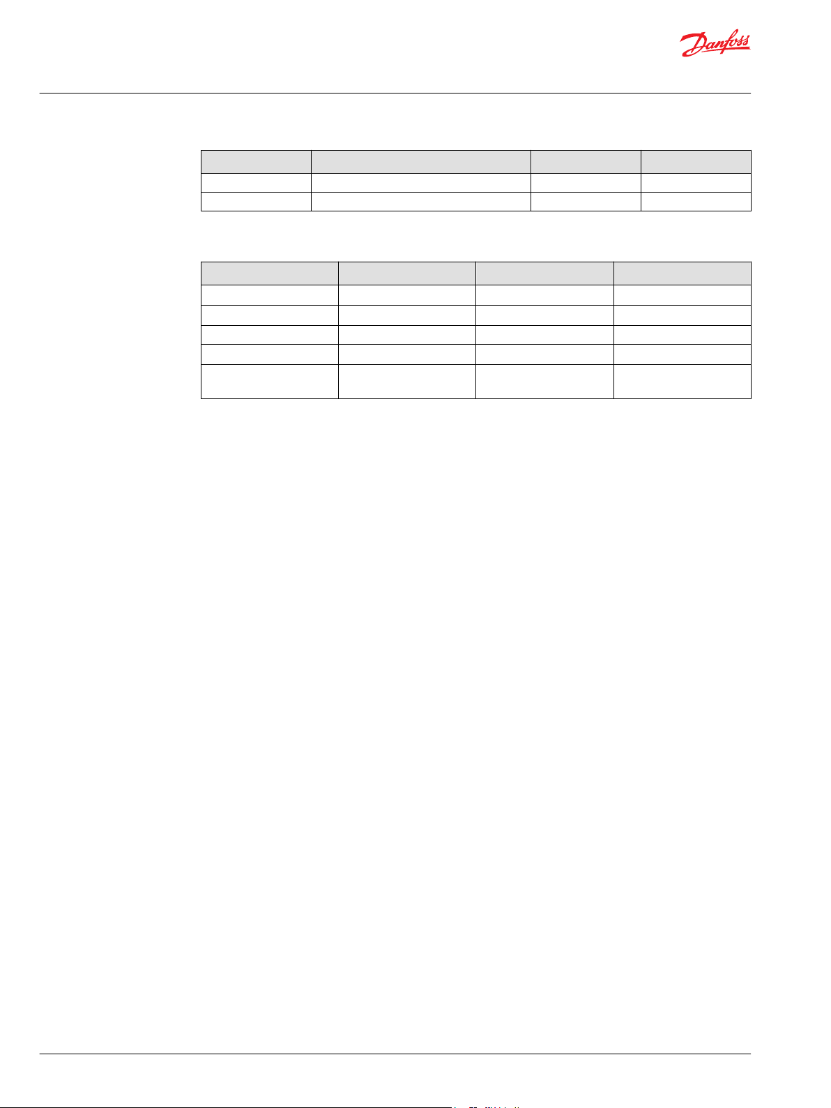
Service Manual
H1T 045/053, 060/068 Axial Piston Tandem Pumps
Torque Chart
Item Fastener Wrench size Torque
V020 Charge pressure adjusting screw 6 mm internal hex NA
V022 Charge pressure locking nut 19 mm hex 40 N•m [30 lbf•ft]
Plug Size and Torque Chart
Item O-ring plug Wrench size Torque
B015 7/16 - 20 3/16 internal hex 20 N•m [15 lbf•ft]
B020 (45/53) 1-1/16 - 12 9/16 internal hex 48 N•m [35 lbf•ft]
B020 (60/68) 1-3/8 - 12 5/8 internal hex 148 N•m [109 lbf•ft]
D065 7/16 - 20 3/16 internal hex 12 N•m [9 lbf•ft]
G250 9/16 - 18 1/4 internal hex
45 N•m [33 lbf•ft]
(hardened plug)
78 | © Danfoss | December 2021 AX152886481761en-000501
Page 79

Danfoss
Power Solutions GmbH & Co. OHG
Krokamp 35
D-24539 Neumünster, Germany
Phone: +49 4321 871 0
Danfoss
Power Solutions ApS
Nordborgvej 81
DK-6430 Nordborg, Denmark
Phone: +45 7488 2222
Danfoss
Power Solutions (US) Company
2800 East 13th Street
Ames, IA 50010, USA
Phone: +1 515 239 6000
Danfoss
Power Solutions Trading
(Shanghai) Co., Ltd.
Building #22, No. 1000 Jin Hai Rd
Jin Qiao, Pudong New District
Shanghai, China 201206
Phone: +86 21 2080 6201
Products we offer:
Hydro-Gear
www.hydro-gear.com
Daikin-Sauer-Danfoss
www.daikin-sauer-danfoss.com
Cartridge valves
•
DCV directional control
•
valves
Electric converters
•
Electric machines
•
Electric motors
•
Gear motors
•
Gear pumps
•
Hydraulic integrated
•
circuits (HICs)
Hydrostatic motors
•
Hydrostatic pumps
•
Orbital motors
•
PLUS+1® controllers
•
PLUS+1® displays
•
PLUS+1® joysticks and
•
pedals
PLUS+1® operator
•
interfaces
PLUS+1® sensors
•
PLUS+1® software
•
PLUS+1® software services,
•
support and training
Position controls and
•
sensors
PVG proportional valves
•
Steering components and
•
systems
Telematics
•
Danfoss Power Solutions is a global manufacturer and supplier of high-quality hydraulic and
electric components. We specialize in providing state-of-the-art technology and solutions
that excel in the harsh operating conditions of the mobile off-highway market as well as the
marine sector. Building on our extensive applications expertise, we work closely with you to
ensure exceptional performance for a broad range of applications. We help you and other
customers around the world speed up system development, reduce costs and bring vehicles
and vessels to market faster.
Danfoss Power Solutions – your strongest partner in mobile hydraulics and mobile
electrification.
Go to www.danfoss.com for further product information.
We offer you expert worldwide support for ensuring the best possible solutions for
outstanding performance. And with an extensive network of Global Service Partners, we also
provide you with comprehensive global service for all of our components.
Local address:
Danfoss can accept no responsibility for possible errors in catalogues, brochures and other printed material. Danfoss reserves the right to alter its products without notice. This also applies to products
already on order provided that such alterations can be made without subsequent changes being necessary in specifications already agreed.
All trademarks in this material are property of the respective companies. Danfoss and the Danfoss logotype are trademarks of Danfoss A/S. All rights reserved.
©
Danfoss | December 2021 AX152886481761en-000501
 Loading...