

Page 1
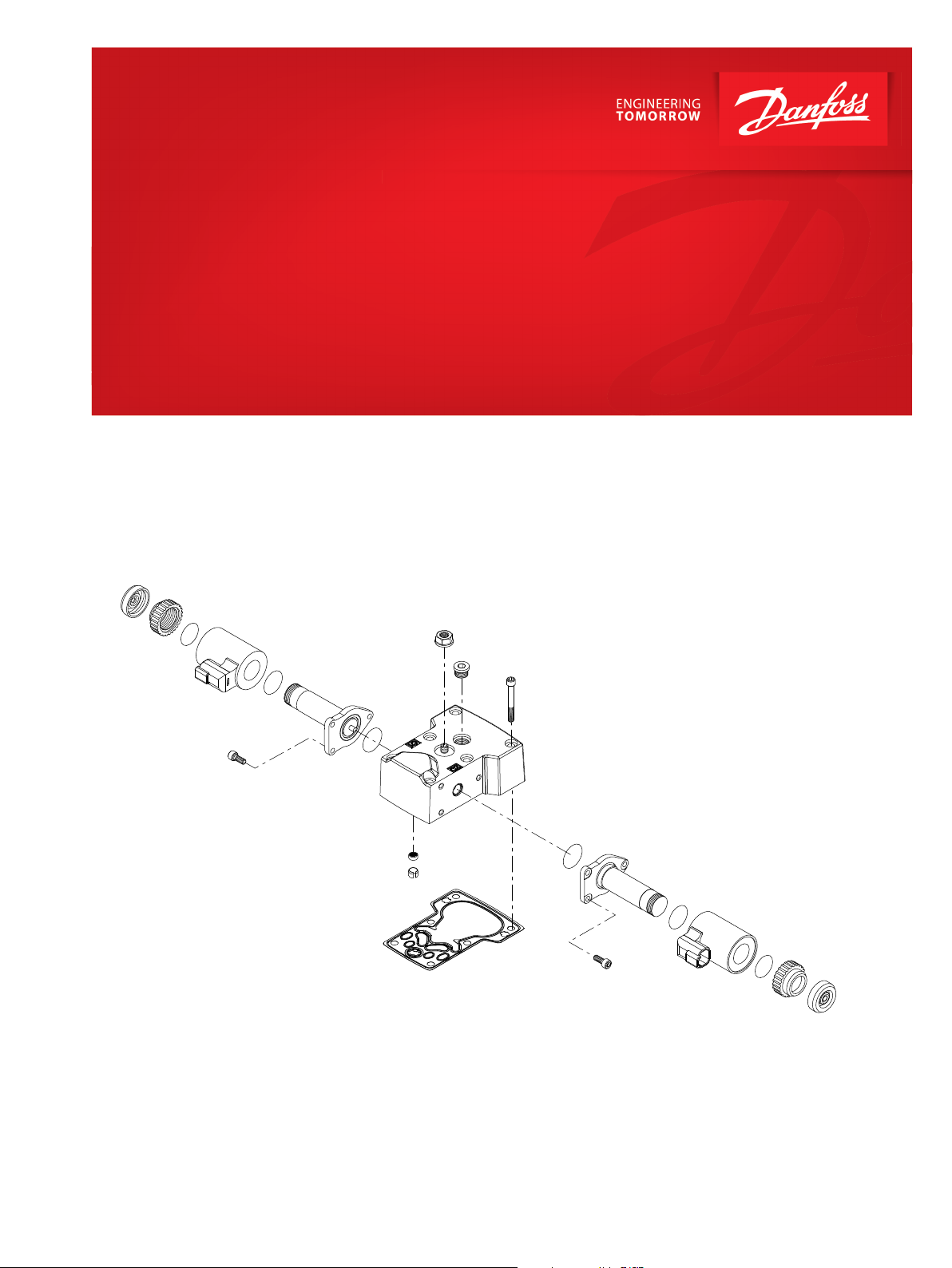
Parts Manual
H1P 45 and 53cc
Variable displacement pump
www.danfoss.com
Page 2
Parts Manual
H1P 45 and 53cc
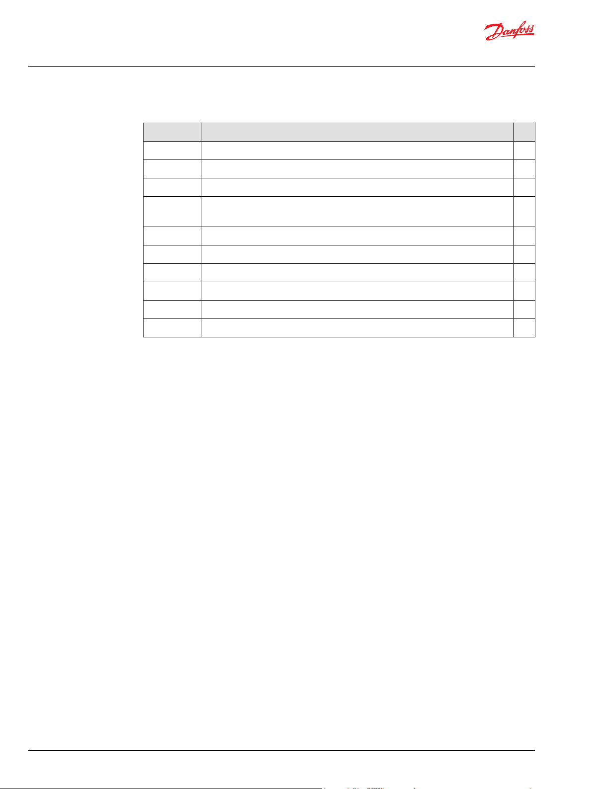
Revision history Table of revisions
Date Changed Rev
March 2022 Updated H1 and H2 auxiliary mounting part numbers 1301
August 2021 Updated various part numbers; added new pressure settings; added SB-2021-014 1201
December 2020 Moved pressure limiter screens from housing kits to pressure limiter kits 1101
May 2020 Changed document number from 'AX00000029' to 'AX152886481285' and updated CCO
part numbers
January 2020 Updated control gasket part numbers 0907
July 2019 Added new options 0906
June 2019 Updated part numbers; added new options 0905
February 2019 Added various new options 0904
November 2018 Added control options T6, T7, T8 and T9 0903
July 2018 Updated to Engineering Tomorrow format and added SB-2018-025 0902
1009
2 | © Danfoss | March 2022 AX152886481285en-001301
Page 3

Parts Manual
H1P 45 and 53cc
Contents
General information
Service parts identification........................................................................................................................................................... 5
Nameplate...........................................................................................................................................................................................5
Date code............................................................................................................................................................................................ 6
About service bulletins...................................................................................................................................................................6
Procedure to identify a part..........................................................................................................................................................7
Regional part numbers............................................................................................................................................................. 7
Example of a part identification (H1P 45/53)....................................................................................................................7
Adobe Acrobat 2-page viewing..................................................................................................................................................8
Order code.......................................................................................................................................................................................... 9
Common parts and special hardware
Special hardware H1, M1, P1......................................................................................................................................................10
Special hardware P4-PN...............................................................................................................................................................14
Controls
Control A2, A3................................................................................................................................................................................. 16
Control A4, A5................................................................................................................................................................................. 18
Control A7.........................................................................................................................................................................................20
Control A8.........................................................................................................................................................................................22
Control A9, B1..................................................................................................................................................................................24
Control B5.........................................................................................................................................................................................26
Control B7.........................................................................................................................................................................................28
Control B8.........................................................................................................................................................................................30
Control B9.........................................................................................................................................................................................32
Control C2.........................................................................................................................................................................................34
Control C3.........................................................................................................................................................................................36
Control E2......................................................................................................................................................................................... 38
Control E5......................................................................................................................................................................................... 40
Control E6, E7...................................................................................................................................................................................42
Control E8......................................................................................................................................................................................... 44
Control F1, F2...................................................................................................................................................................................46
Control F4......................................................................................................................................................................................... 48
Control H2, H3.................................................................................................................................................................................50
Control H6, H7.................................................................................................................................................................................52
Control H8, H9.................................................................................................................................................................................54
Control J1, J2....................................................................................................................................................................................56
Control J3, J4....................................................................................................................................................................................58
Control M1, M2............................................................................................................................................................................... 60
Control M3, M4............................................................................................................................................................................... 62
Control M5, M6............................................................................................................................................................................... 64
Control N1, N2.................................................................................................................................................................................66
Control N3, N4.................................................................................................................................................................................68
Control N5, N6.................................................................................................................................................................................70
Control N7, N8.................................................................................................................................................................................72
Control ND, NN............................................................................................................................................................................... 74
Control P5......................................................................................................................................................................................... 76
Control P6, P7..................................................................................................................................................................................78
Control P8, P9..................................................................................................................................................................................80
Control R3......................................................................................................................................................................................... 82
Control R4......................................................................................................................................................................................... 84
Control T6, T7.................................................................................................................................................................................. 86
Control T8, T9.................................................................................................................................................................................. 88
Control U1, U2.................................................................................................................................................................................90
Control U3, U4.................................................................................................................................................................................92
Displacement limitation
Displacement limitation B-D......................................................................................................................................................94
Displacement limitation E-N......................................................................................................................................................98
Orifice
©
Danfoss | March 2022 AX152886481285en-001301 | 3
Page 4

Parts Manual
H1P 45 and 53cc
Contents
End cap
Housing
Shaft
Auxiliary mounting
High pressure setting
Charge pump
Overhaul seal kit
Service bulletin
H1P 45/53 orifice..........................................................................................................................................................................100
End cap D6, D8............................................................................................................................................................................. 104
End cap E5, E6...............................................................................................................................................................................106
End cap E9, F1...............................................................................................................................................................................108
End cap F2, F3...............................................................................................................................................................................110
End cap G2, G9..............................................................................................................................................................................112
End cap J7.......................................................................................................................................................................................114
Housing F, J....................................................................................................................................................................................116
Shaft F2-G5.....................................................................................................................................................................................118
Auxiliary mounting H1-NN.......................................................................................................................................................120
Port A................................................................................................................................................................................................124
High pressure setting F01-F07.......................................................................................................................................... 124
High pressure setting J18-J48............................................................................................................................................126
High pressure setting K18-K48..........................................................................................................................................128
High pressure setting L15-L48...........................................................................................................................................132
Port B................................................................................................................................................................................................136
High pressure setting F01-F07.......................................................................................................................................... 136
High pressure setting J18-J48............................................................................................................................................138
High pressure setting K18-K48..........................................................................................................................................140
High pressure setting L15-L48...........................................................................................................................................144
Charge pump, charge pressure relief, filtration................................................................................................................148
H1P 45/53 seal kit........................................................................................................................................................................ 150
SB-2006-030...................................................................................................................................................................................151
SB-2007-004...................................................................................................................................................................................152
SB-2007-023...................................................................................................................................................................................153
SB-2007-026...................................................................................................................................................................................154
SB-2007-033...................................................................................................................................................................................155
SB-2008-038...................................................................................................................................................................................157
SB-2008-056...................................................................................................................................................................................159
SB-2009-007...................................................................................................................................................................................160
SB-2009-028...................................................................................................................................................................................162
SB-2009-043...................................................................................................................................................................................163
SB-2009-051...................................................................................................................................................................................164
SB-2010-020...................................................................................................................................................................................166
SB-2011-020...................................................................................................................................................................................167
SB-2013-019...................................................................................................................................................................................169
SB-2016-033...................................................................................................................................................................................170
SB-2018-025...................................................................................................................................................................................171
SB-2020-029...................................................................................................................................................................................172
SB-2021-014...................................................................................................................................................................................173
4 | © Danfoss | March 2022 AX152886481285en-001301
Page 5
Made in U.S.A.
Serial No.
A-10-36-23456
Model Code
Model No./Ident No.
H1P045 R A A2 C3 N
F1 F G5 NN K 45 K 45
B L 20 PN NNN NNN
1403032
Parts Manual
H1P 45 and 53cc
General information
Service parts identification
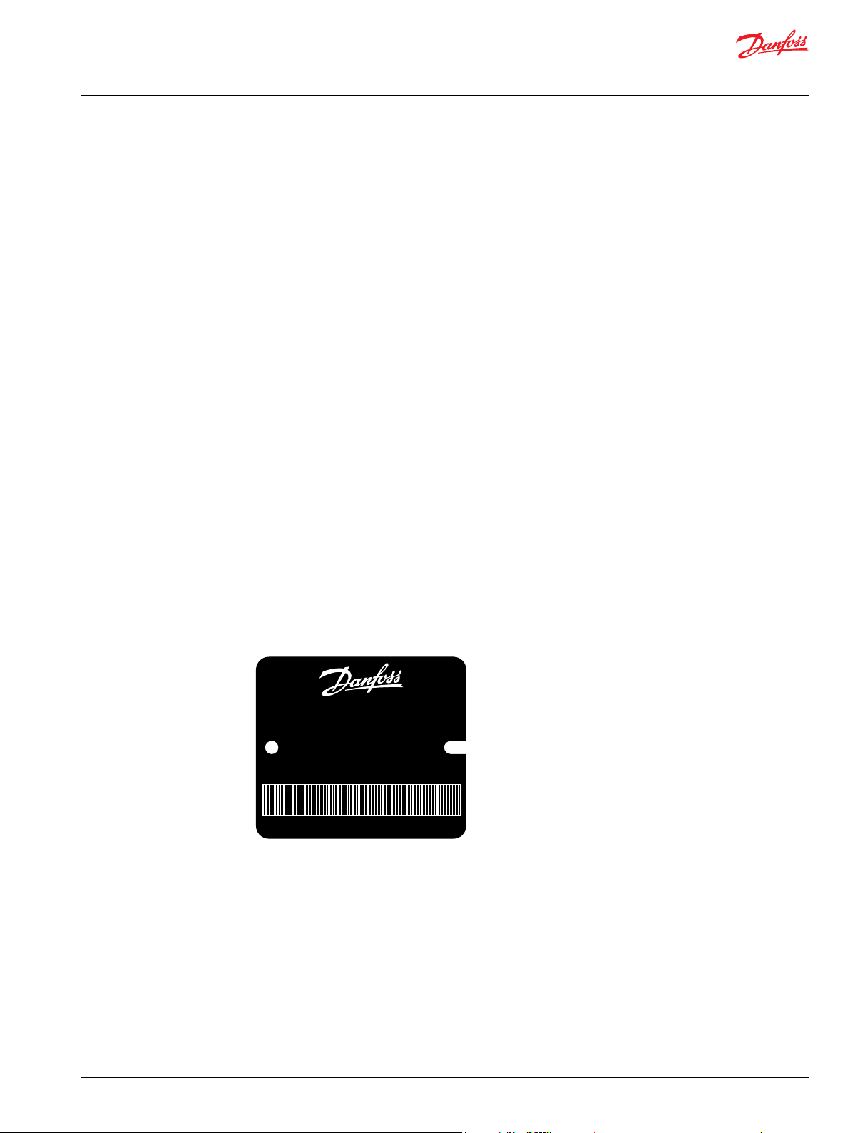
Nameplate
The following information and procedure is used to identify the module group, item number,
manufacture date, part number, and part name of the parts included in the H1P 45 and 53.
The parts listed include all parts which may be used when performing either “Minor Repairs”, “Major
Repairs” or “Conversions” on the .
Each unit will have a nameplate affixed to the housing. The nameplate of the will include the following
information:
Model code
The Danfoss model code completely defines the specific unit and must be used when ordering parts to
service this product.
Model/material number
The Danfoss model number (also known as material number) is used by the factory in manufacturing. On
repeat orders, a complete unit can be ordered by the model number.
Serial number
The Danfoss serial number is used to identify the manufacture date and the unit sequence in the build.
The serial number is also used to identify the units warranty time period.
The letter code indicates the location of original manufacture (assembly).
The first number (2 digits) indicates the year of manufacture. The second number (2 digits) indicates the
calendar week of manufacture.
The third number (5 digits) is a sequential number used to identify a specific unit.
©
Danfoss | March 2022 AX152886481285en-001301 | 5
Page 6
Parts Manual
H1P 45 and 53cc
General information
Date code
About service bulletins
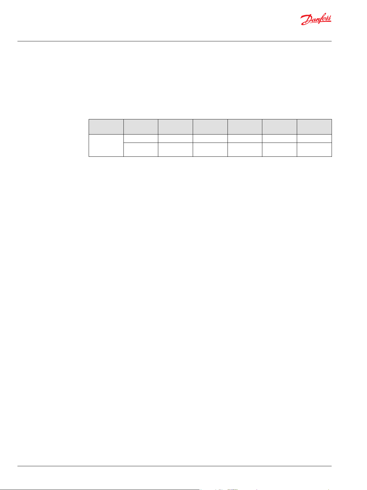
The date code is defined as the year and week of manufacture. The same item number may list more than
one part number. This indicates that there is more than one configuration for that item number. You will
see that there are different date codes for the different part numbers. Find the date code of your unit
from the nameplate to determine which service part number you need to order.
Example: The service part desired is item G30
Order Code Item Date Begin Date End Part Number Part Name Qty. per
80 G30 89-17 8000243 End cap gasket 1
G30 89-16 8000151 End cap gasket
(SB-1995-006)
Model/Kit
1
All units using this order code with a date code prior to 89-17 must use part number “8000151.” All units
with a date code of 89-17 and newer must use part number “8000243.”
A Service Bulletin Number (SB-_ _ _ _ - _ _ _) may follow the “Part Name” of the part you desire. You must
read that Service Bulletin prior to ordering that part. The information contained in these Service Bulletins,
as of the print date of this bulletin, are included at the end of this manual. Service Bulletins contain more
detailed information such as interchangeability, what additional parts are involved, etc. It is suggested
that you add additional Service Bulletins to this manual as you receive them.
6 | © Danfoss | March 2022 AX152886481285en-001301
Page 7

Parts Manual
H1P 45 and 53cc
General information
Procedure to identify a part
The modular design of this product results in a simplified service parts list and part number identification
procedure.
The same item numbers are used for same part names on all units within a product type. A part number
that has another number following it in parentheses is done to make this a world wide manual.
Regional part numbers
Some part numbers are region specific and should be ordered accordingly.
As an example, the part number (example: 314583 (9008000-0118) will be used. The first number is sold
in Germany. The number in parentheses is sold in the United States. Customers would order
9008000-0118 if ordering the part in the United States.
Example of a part identification (H1P 45/53)
The nameplate on an H1 pump has an Order Code of H1P045 R A A A2 C3 N F1 F G5 NN J 35 J 35 B L 20 PN
NNN NNN. Use the following procedures to determine the part number of the drive shaft used on this
pump.
1. Referring to the input shaft module in the Order code on page 9, the input shaft option for this
pump is identified by the code "G5."
H1P045 R A A A2 C3 N F1 F G5 NN J 35 J 35 B L 20 PN NNN NNN
2. Referring to the service parts list, find the shaft group and the order code that relates to this unit (G5).
The shaft is found to be item J100 and part number 141954.
©
Danfoss | March 2022 AX152886481285en-001301 | 7
Page 8
Parts Manual
H1P 45 and 53cc
General information
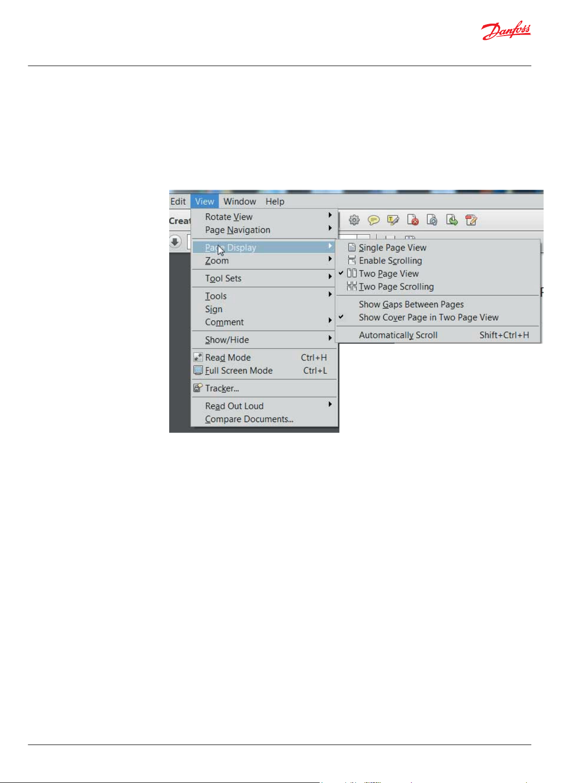
Adobe Acrobat 2-page viewing
While viewing manual in Adobe Acrobat, the following settings need to be applied to ensure proper
page display.
1. Select “View” → “Page Display” → “Two Page View”
2. Select “View” → “Page Display” → “Show Cover Page in Two Page View”
8 | © Danfoss | March 2022 AX152886481285en-001301
Page 9
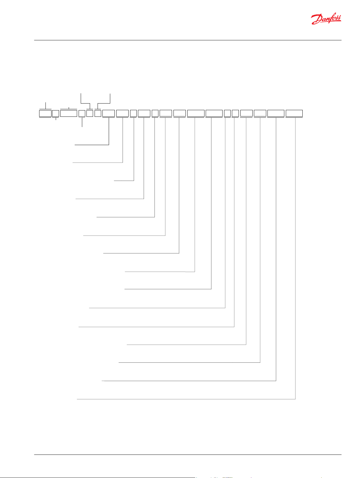
Orifice
Displacement limitation
End cap
Control
Mounting flange
Input shaft
Auxiliary mounting
High pressure setting, port A
High pressure setting, port B
Charge pump
Filtration
Paint and nametag
Settings
Charge relief pressure setting
Special hardware features
P
F
N
B
PN
Series
Frame
Size
D F
G
E
H J SLTK M N
NNNXNNNK45K45
Y
W
V
20
Product Type
R
Rotation
NNG5
F1C3A2
H1
045
A A
Product
Version
Port
Configuration
Parts Manual
H1P 45 and 53cc
General information
Order code
©
Danfoss | March 2022 AX152886481285en-001301 | 9
Page 10
B010
B010
QD075
D070
C020
C010
C025
C010
QC050
QC10
C20
C15
C25
QC050
QC10
C20
C15
C25
(H1, M1, NN, P1, P5, P6, PN)(H1, M1, NN, P1, P5, P6, PN)
(M2, N2, P2, P4)(M2, N2, P2, P4)
D692
D703
(H1)
Parts Manual
H1P 45 and 53cc
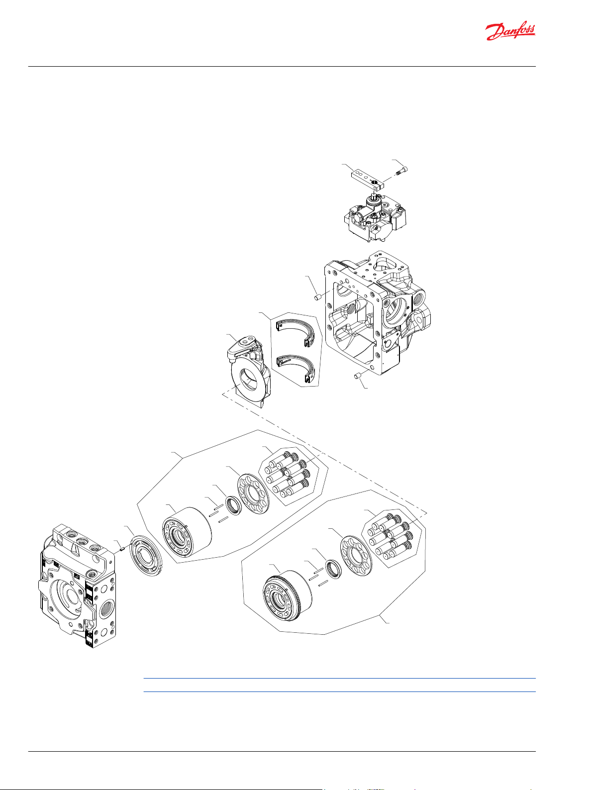
Common parts and special hardware
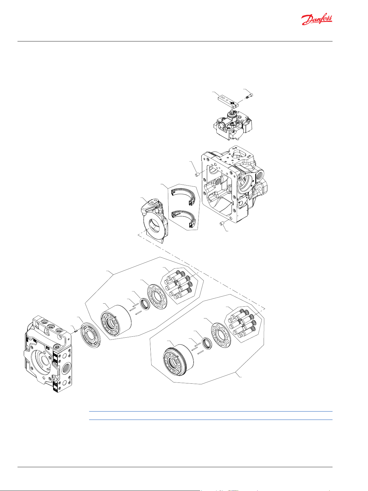
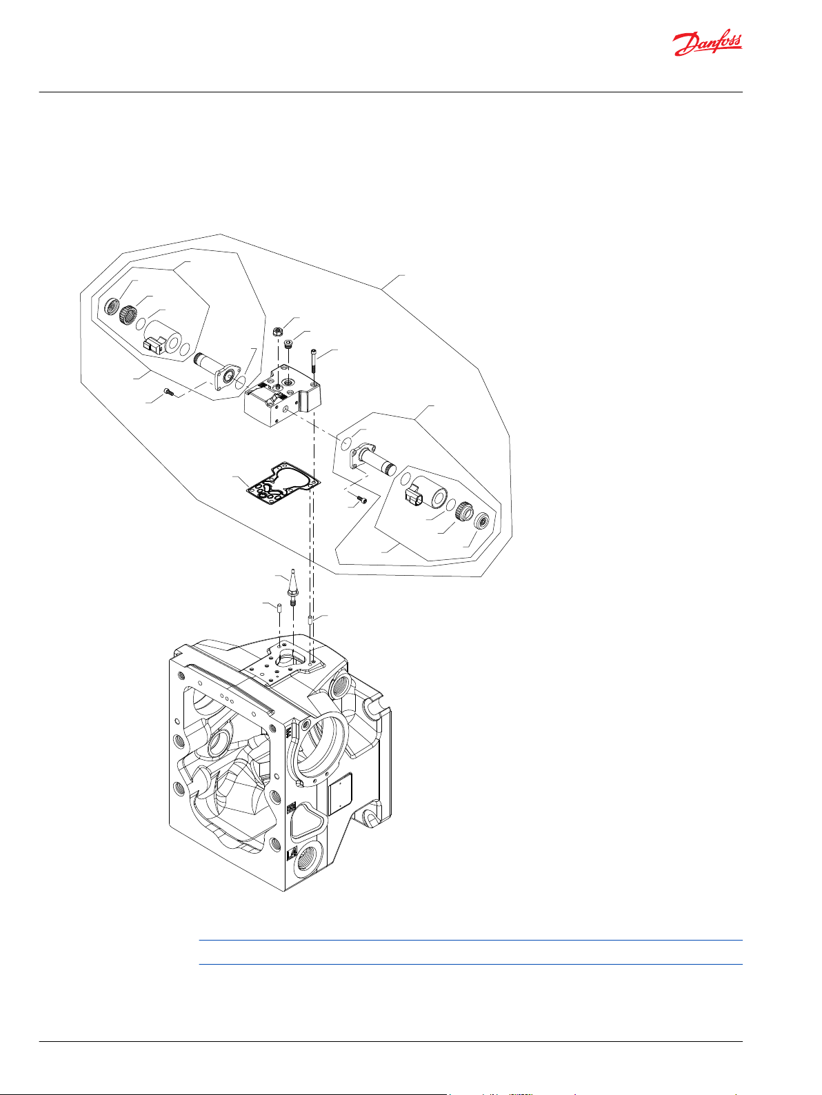
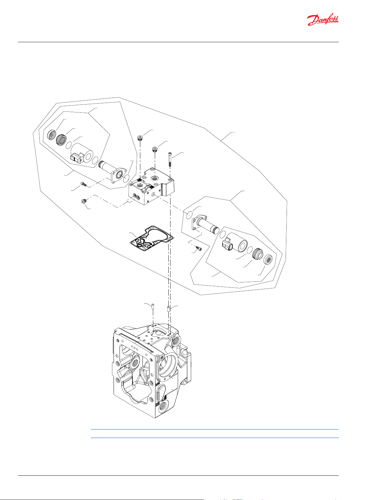
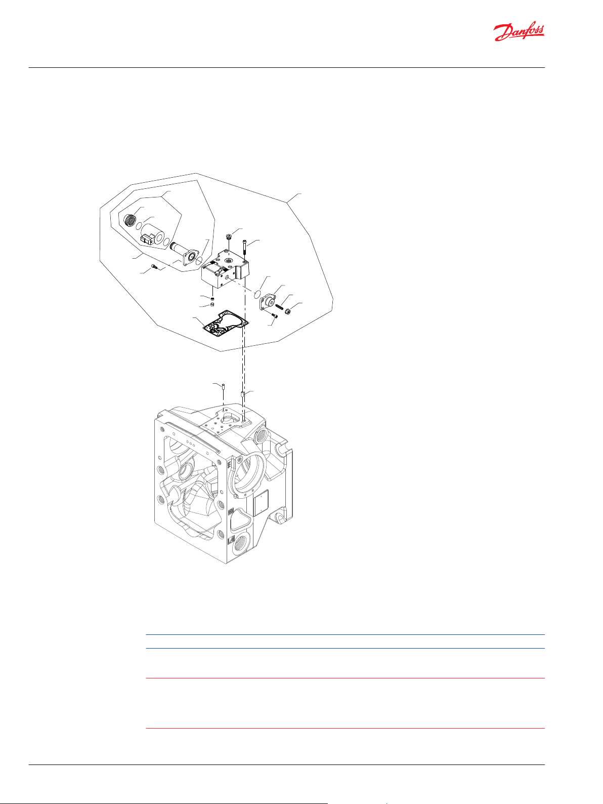
H1P 45/53 special hardware H1, M1, P1
Parts configuration
Generic control, housing, and end cap used to show part location only.
10 | © Danfoss | March 2022 AX152886481285en-001301
Page 11
Parts Manual
H1P 45 and 53cc
Common parts and special hardware
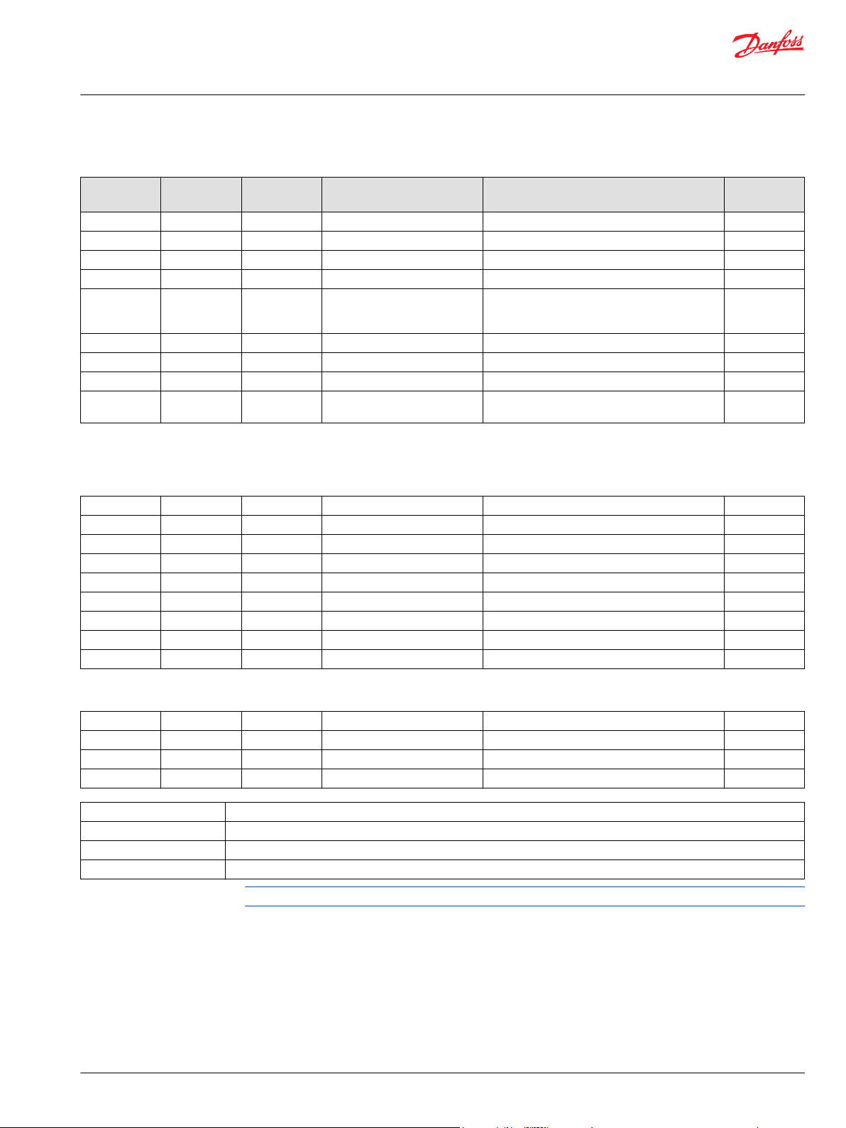
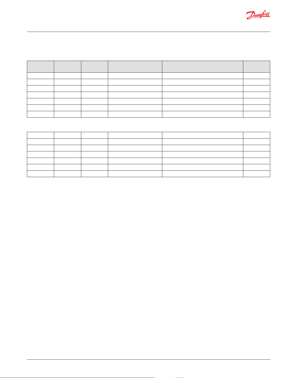
Common parts
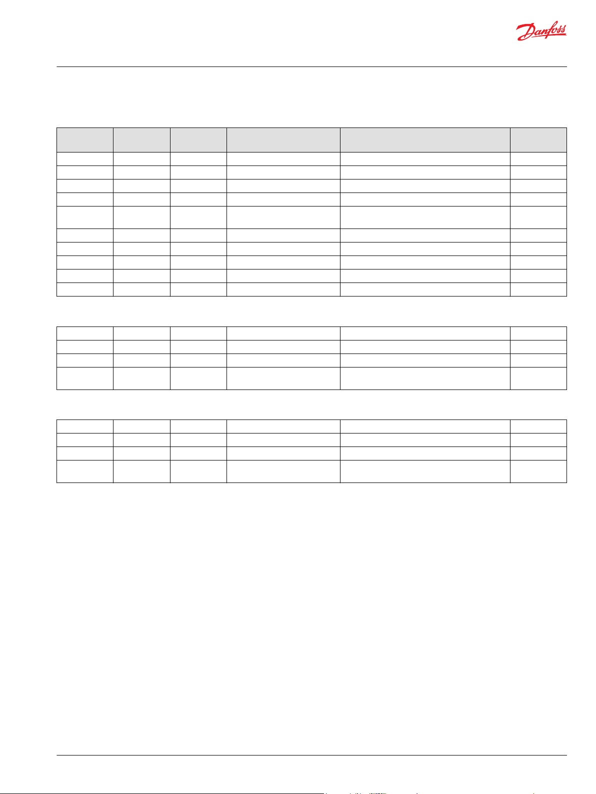
Item Date Begin Date End Part Number Part Name Qty. per
B010 07-19 5000757 Dowel pin 2
C020 07-19 9004700-1907 Valve plate pin, 1
C20 07-19 141946 Slipper retainer 1
C25 07-19 4700091 Slipper hold down pin 3
D070 12-21 11068328 Swashplate (SB-2008-056 on page 159,
SB-2009-043 on page 163 & SB-2011-020 on page
167)
D070 07-19 12-20 11098280 Swashplate replacement kit 1
QC10 07-19 11020841 Slipper/piston kit, 45cc 1
QC10 07-19 11020932 Slipper/piston kit, 53cc 1
QD075 07-19 11085533 Swashplate bearing kit (SB-2010-020 on page
166)
Model/Kit
1
1
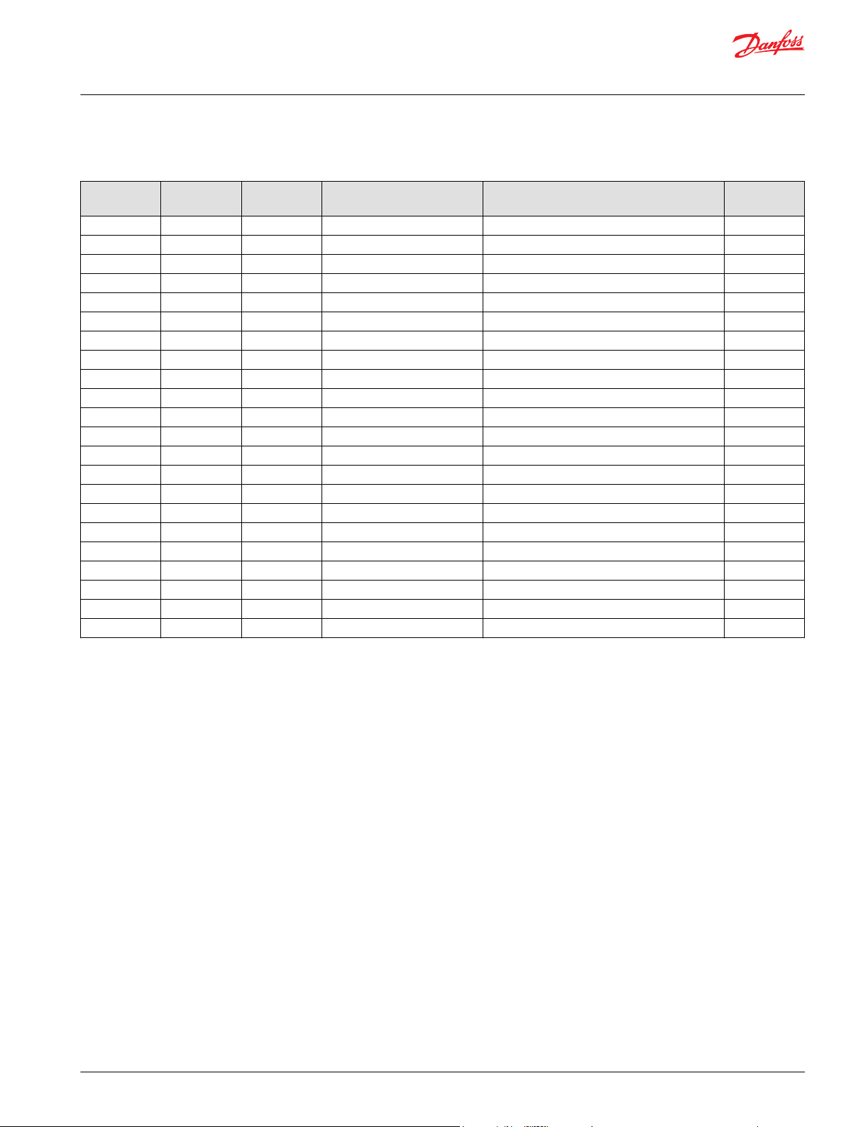
Special hardware
Order code: H1
C15 14-33 140625 Slipper retainer ball guide 1
C010 14-33 141631 Cylinder block kit, 45cc 1
C010 14-33 141632 Cylinder block kit, 53cc 1
C025 14-33 11071901 Valve plate kit, CW 1
C025 14-33 11071912 Valve plate kit, CCW 1
D692 14-33 11185958 Control handle 1
D703 14-33 11173701 Screw, M6 x 20 1
QC50 14-33 141553 Cylinder block assembly, 45cc 1
QC50 14-33 141554 Cylinder block assembly, 53cc 1
Order code: M1
C15 07-19 140625 Slipper retainer ball guide 1
C010 07-19 141631 Cylinder block kit, 45cc 1
C025 07-19 11018336 Valve plate, CW 1
QC50 07-19 141553 Cylinder block assembly, 45cc 1
M1 Replaced with P1 (H1P045L, H1P053L, H1P053R)
M2 Replaced with P2
M4 Replaced with P4
NN Replaced with PN
Parts continue to the next two pages.
©
Danfoss | March 2022 AX152886481285en-001301 | 11
Page 12
B010
B010
QD075
D070
C020
C010
C025
C010
QC050
QC10
C20
C15
C25
QC050
QC10
C20
C15
C25
(H1, M1, NN, P1, P5, P6, PN)(H1, M1, NN, P1, P5, P6, PN)
(M2, N2, P2, P4)(M2, N2, P2, P4)
D692
D703
(H1)
Parts Manual
H1P 45 and 53cc
Common parts and special hardware
Parts configuration
Generic control, housing, and end cap used to show part location only.
12 | © Danfoss | March 2022 AX152886481285en-001301
Page 13
Parts Manual
H1P 45 and 53cc
Common parts and special hardware
Order code: P1
Item Date Begin Date End Part Number Part Name Qty. per
C15 09-13 140625 Slipper retainer ball guide 1
C010 09-13 141631 Cylinder block kit, 45 cc 1
C010 09-13 141632 Cylinder block kit, 53 cc 1
C025 09-13 11071901 Valve plate kit, CW 1
C025 09-13 11071912 Valve plate kit, CCW 1
QC50 09-13 141553 Cylinder block assembly, 45 cc 1
QC50 09-13 141554 Cylinder block assembly, 53 cc 1
Order code: P2
C15 09-13 140625 Slipper retainer ball guide 1
C010 09-13 11030567 Cylinder block kit, 45 cc, with speed ring 1
C010 09-13 11030568 Cylinder block kit, 53 cc, with speed ring 1
C025 09-13 11071901 Valve plate kit, CW 1
C025 09-13 11071912 Valve plate kit, CCW 1
QC50 09-13 11030569 Cylinder block assembly, 45 cc, with speed ring 1
QC50 09-13 11030570 Cylinder block assembly, 53 cc, with speed ring 1
Model/Kit
©
Danfoss | March 2022 AX152886481285en-001301 | 13
Page 14

B010
B010
QD075
D070
C020
C010
C025
C010
QC050
QC10
C20
C15
C25
QC050
QC10
C20
C15
C25
(H1, M1, NN, P1, P5, P6, PN)(H1, M1, NN, P1, P5, P6, PN)
(M2, N2, P2, P4)(M2, N2, P2, P4)
D692
D703
(H1)
Parts Manual
H1P 45 and 53cc
Common parts and special hardware
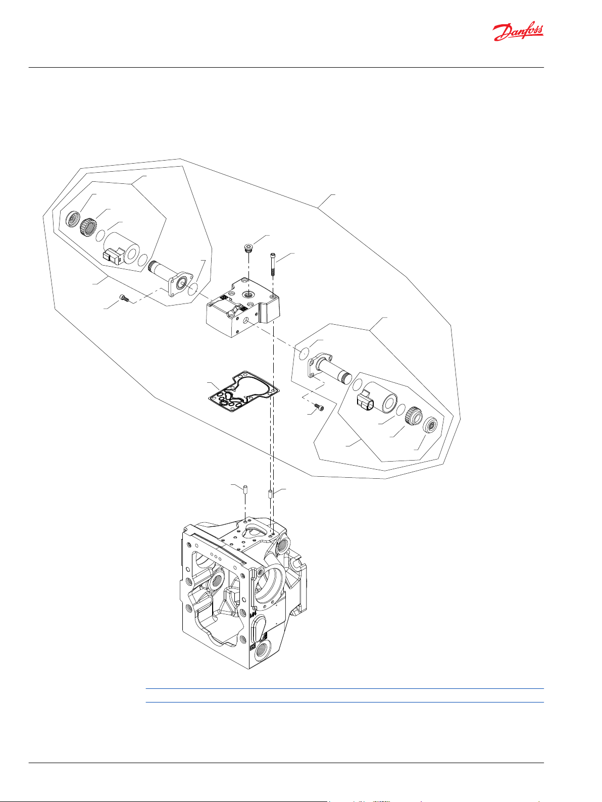
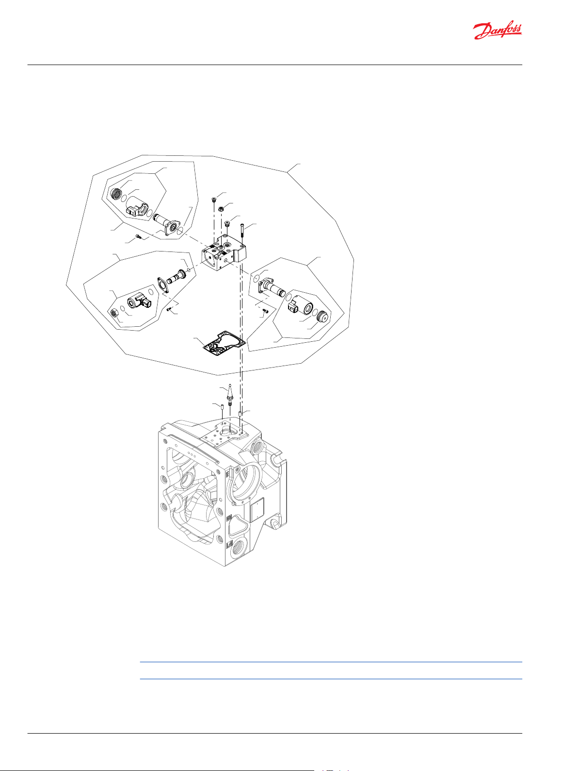
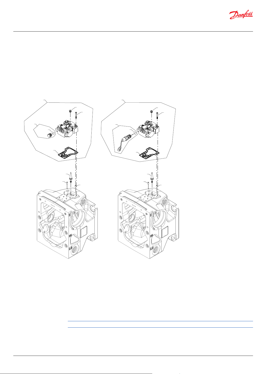
H1P 45/53 special hardware P4, P6, PN
Parts configuration
Generic housing, control, and end cap used to show part location only.
14 | © Danfoss | March 2022 AX152886481285en-001301
Page 15
Parts Manual
H1P 45 and 53cc
Common parts and special hardware
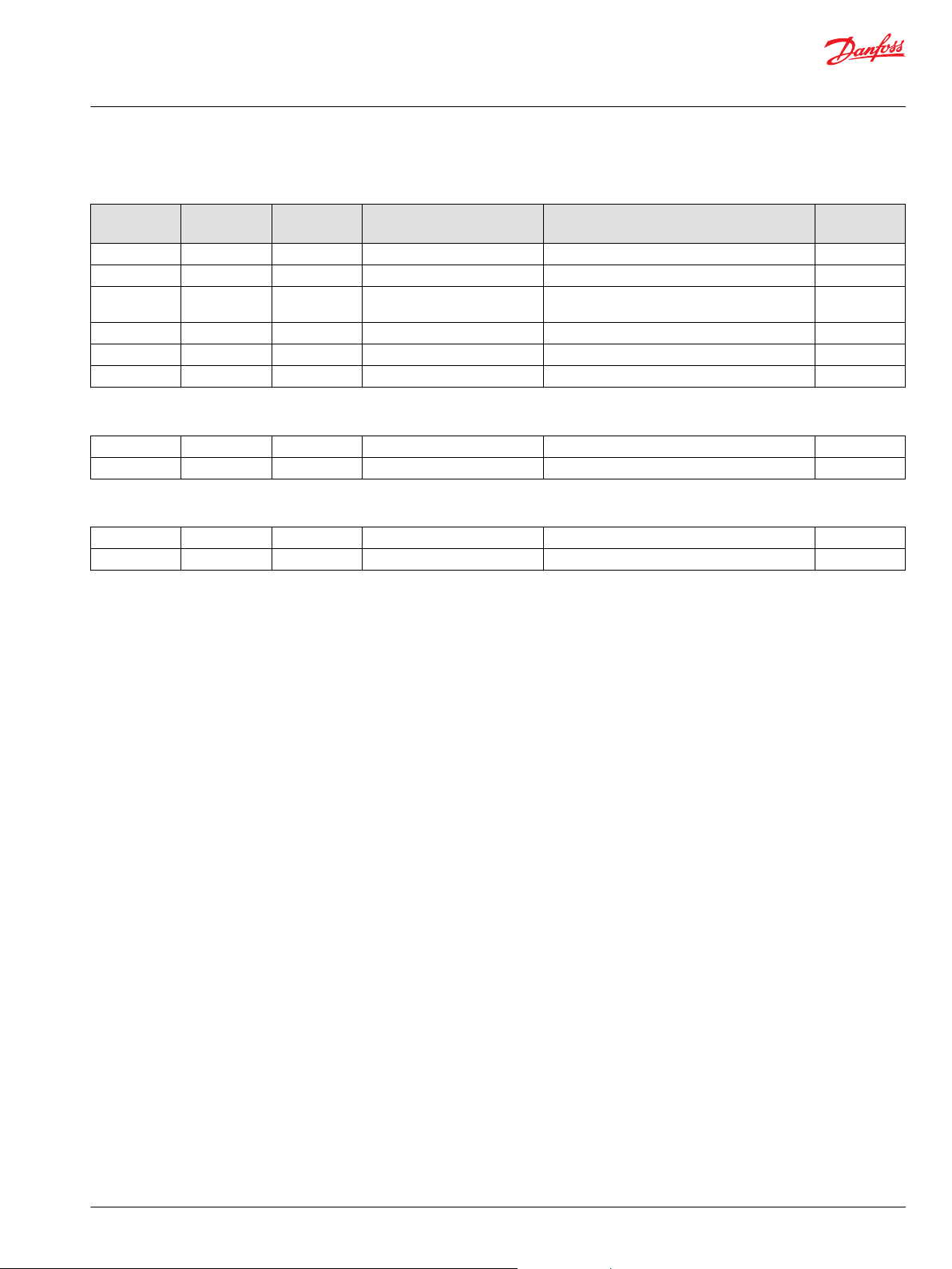
Common parts
Item Date Begin Date End Part Number Part Name Qty. per
B010 07-19 5000757 Dowel pin 2
C020 07-19 9004700-1907 Valve plate pin, 1
C20 07-19 141946 Slipper retainer 1
C25 07-19 4700091 Slipper hold down pin 3
D070 12-21 11068328 Swashplate (SB-2008-056 on page 159,
SB-2009-043 on page 163 & SB-2011-020 on page
167)
D070 07-19 12-20 11098280 Swashplate replacement kit 1
QC10 07-19 11020841 Slipper/piston kit, 45 cc 1
QC10 07-19 11020932 Slipper/piston kit, 53 cc 1
QD075 07-19 11085533 Swashplate bearing kit (SB-2010-020 on page
166)
Model/Kit
1
1
Special hardware
Order code: P4
C15 09-13 140625 Slipper retainer ball guide 1
C010 09-13 11030567 Cylinder block kit, 45 cc, with speed ring 1
C010 09-13 11030568 Cylinder block kit, 53 cc, with speed ring 1
C025 09-13 11071901 Valve plate kit, CW 1
C025 09-13 11071912 Valve plate kit, CCW 1
QC50 09-13 11030569 Cylinder block assembly, 45 cc, with speed ring 1
QC50 09-13 11030570 Cylinder block assembly, 53 cc, with speed ring 1
Order code: P6
C15 13-20 11112897 Slipper retainer ball guide, coated 1
C010 13-20 11132003 Cylinder block kit, 45 cc 1
C010 13-20 11132004 Cylinder block kit, 53 cc 1
C025 09-13 11071912 Valve plate kit, CCW 1
QC50 13-20 141553 Cylinder block assembly, 45 cc 1
QC50 13-20 141554 Cylinder block assembly, 53 cc 1
Order code: PN
C15 09-13 140625 Slipper retainer ball guide 1
C010 09-13 141631 Cylinder block kit, 45 cc 1
C010 09-13 141632 Cylinder block kit, 53 cc 1
C025 09-13 11071901 Valve plate kit, CW 1
C025 09-13 11071912 Valve plate kit, CCW 1
QC50 09-13 141553 Cylinder block assembly, 45 cc 1
QC50 09-13 141554 Cylinder block assembly, 53 cc 1
©
Danfoss | March 2022 AX152886481285en-001301 | 15
Page 16
E100 912E
D300
D300
D200
QD25
*QD26
QD27
D050
D050
QD27
*QD26
QD100
QD25
D250
*D060
QD28
QD29
QD28
QD29
D065
*D150
Parts Manual
H1P 45 and 53cc
Controls
H1P control A2, A3
Generic housing shown.
* Included in overhaul seal kit Q210
16 | © Danfoss | March 2022 AX152886481285en-001301
Page 17

Parts Manual
H1P 45 and 53cc
Controls
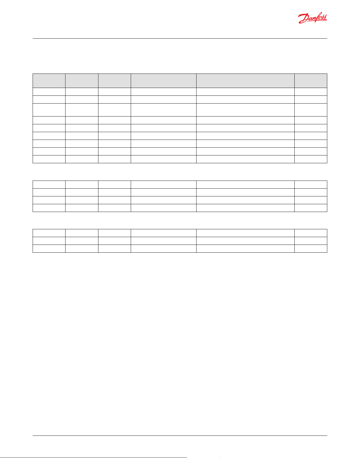
Common parts
Item Date Begin Date End Part Number Part Name Qty. per
D050 10-48 716860 Screw, M5 x 12 6
D060 10-48 612291 (9003508-0008) Seal nut, M8 1
D065 10-48 327007 Plug assembly (SAE) 1
D150 10-48 11227209 Control gasket (SB-2016-033 on page 170) 1
D200 10-48 11202172 Swash plate feedback link (SB-2018-025 on page
171)
D250 10-48 505038 Screw, M6 x 45 6
D300 10-48 310979 Dowel pin 2
QD26 10-48 11001952 O-ring 2
QD28 10-48 063172 O-ring 2
Order code: A2
QD25 10-48 11012457 Proportional solenoid, 12v 2
QD27 10-48 11028018 Coil kit, 12v, DEUTSCH connector 2
QD29 10-48 11027046 Coil nut 2
QD100 10-48 11019680 EDC kit, 12v, DEUTSCH connector, fast 1
Model/Kit
1
Order code: A3
QD25 10-48 11012459 Proportional solenoid, 24v 2
QD27 10-48 11028019 Coil kit, 24v, DEUTSCH connector 2
QD29 10-48 11028024 Coil nut 2
QD100 10-48 11019681 EDC kit, 24v, DEUTSCH connector, fast 1
©
Danfoss | March 2022 AX152886481285en-001301 | 17
Page 18
QD27
QD28
QD29
QD30
QD27
QD28
QD29
QD30
D300
D300
D200
QD25
*QD26
D050
D050
*QD26
QD100
QD25
D250
*D060
D065
*D150
Parts Manual
H1P 45 and 53cc
Controls
H1P control A4, A5
A4 and A5 configuration
Generic housing shown.
* Included in overhaul seal kit Q210
18 | © Danfoss | March 2022 AX152886481285en-001301
Page 19
Parts Manual
H1P 45 and 53cc
Controls
Common parts
Item Date Begin Date End Part Number Part Name Qty. per
D050 10-48 716860 Screw, M5 x 12 6
D060 10-48 612291 (9003508-0008) Seal nut, M8 1
D065 10-48 327007 Plug assembly 1
D150 10-48 11227209 Control gasket (SB-2016-033 on page 170) 1
D200 10-48 11202172 Swash plate feedback link (SB-2018-025 on page
171)
D250 10-48 505038 Screw, M6 x 45 6
D300 10-48 310979 Dowel pin 2
QD26 10-48 11001952 O-ring 2
QD28 10-48 063172 O-ring 2
QD30 10-48 11027883 Cap 2
Order code: A4
QD25 10-48 140750 Proportional solenoid, 12v 2
QD27 10-48 11004698 Coil kit, 12v, DEUTSCH connector 2
QD29 10-48 11004749 Coil nut 2
QD100 10-48 11019732 EDC kit, 12v, DEUTSCH connector, fast, manual
override
Model/Kit
1
1
Order code: A5
QD25 10-48 140751 Proportional solenoid, 24v 2
QD27 10-48 11004700 Coil kit, 24v, DEUTSCH connector 2
QD29 10-48 11004750 Coil nut 2
QD100 10-48 11019733 EDC kit, 24v, DEUTSCH connector, fast, manual
override
1
©
Danfoss | March 2022 AX152886481285en-001301 | 19
Page 20

D300
D300
D250
QD100
D655
D660
D067
D055
QD25
*QD26
QD27
D050
QD28
QD29
QD30
D050
QD27
*QD26
QD25
QD28
QD29
QD30
D640
D674
D674
D672
*D150
*D611
*D612
Parts Manual
H1P 45 and 53cc
Controls
H1P control A7
Parts configuration
Generic housing shown
* Included in overhaul seal kit
20 | © Danfoss | March 2022 AX152886481285en-001301
Page 21
Parts Manual
H1P 45 and 53cc
Controls
Order code: A7
Item Date Begin Date End Part Number Part Name Qty. per
D050 10-04 716860 Screw, M5 x 12 6
D055 10-04 11040532 Plug assembly 2
D067 10-04 327007 Plug assembly 1
D150 10-04 11227209 Control gasket (SB-2016-033 on page 170) 1
D250 10-04 505038 Screw, M6 x 45 6
D300 10-04 11036469 Dowel pin 2
D612 10-04 21-12 11003126 Plug (SB-2021-014 on page 173) 2
D612 21-13 11223708 Plug 2
D611 10-04 21-12 11066774 O-ring (SB-2021-014 on page 173) 2
D611 21-13 11225703 O-ring 2
D640 10-04 11023348 AC wiring harness 1
D655 10-04 11084827 Connector DTM 06-3S 1
D660 10-04 11084822 Connector DTM 06-6S 1
D672 10-04 11151875 Protection 1
D674 10-04 716860 Screw, M5 x 12 2
QD25 10-04 140750 Proportional solenoid, 12 volt 2
QD26 10-04 11001952 O-ring 2
QD27 10-04 11004698 Coil kit, 12v, DEUTSCH connector 2
QD28 10-04 063172 O-ring 2
QD29 10-04 11004749 Coil nut 2
QD30 10-04 11027883 Cap 2
QD100 10-04 11065118 Automotive control kit, 12v, manual override 1
Model/Kit
©
Danfoss | March 2022 AX152886481285en-001301 | 21
Page 22

D300
D300
QD100
D250
QD25
*QD26
QD27
D050
QD28
QD29
QD30
D050
QD27
*QD26
QD25
QD28
QD29
QD30
D067
D055
D065
*D150
Parts Manual
H1P 45 and 53cc
Controls
H1P control A8
Parts configuration
Generic housing shown.
* Included in overhaul seal kit Q210
22 | © Danfoss | March 2022 AX152886481285en-001301
Page 23

Parts Manual
H1P 45 and 53cc
Controls
Order code: A8
Item Date Begin Date End Part Number Part Name Qty. per
D050 10-48 716860 Screw, M5 x 12 6
D055 10-48 11040532 Plug assembly 2
D065 10-48 327007 Plug assembly 1
D067 10-48 327007 Plug assembly 1
D150 10-48 11227209 Control gasket (SB-2016-033 on page 170) 1
D250 10-48 505038 Screw, M6 x 45 6
D300 10-48 310979 Dowel pin 2
QD25 10-48 140750 Proportional solenoid, 12v, DEUTSCH connector 2
QD26 10-48 11001952 O-ring 2
QD27 10-48 11004698 Coil kit, 12v, DEUTSCH connector 2
QD28 10-48 063172 O-ring 2
QD29 10-48 11004749 Coil nut 2
QD30 10-48 11027883 Cap 2
QD100 10-48 11015803 NFPE control kit, 12V, manual override, DEUTSCH
connector
Model/Kit
1
©
Danfoss | March 2022 AX152886481285en-001301 | 23
Page 24
D300
D300
QD100
D250
QD25
*QD26
QD27
D050
QD28
QD29
QD30
D050
QD27
*QD26
QD25
QD28
QD29
QD30
D065
*D150
Parts Manual
H1P 45 and 53cc
Controls
H1P control A9, B1
Parts configuration
Generic housing shown
* Included in overhaul seal kit Q210
24 | © Danfoss | March 2022 AX152886481285en-001301
Page 25
Parts Manual
H1P 45 and 53cc
Controls
Common parts
Item Date Begin Date End Part Number Part Name Qty. per
D050 10-48 716860 Screw, M5 x 12 6
D065 10-48 327007 Plug assembly 1
D150 10-48 11227209 Control gasket (SB-2016-033 on page 170) 1
D250 10-48 505038 Screw, M6 x 45 6
D300 10-48 310979 Dowel pin 2
QD26 10-48 11001952 O-ring 2
QD28 10-48 063172 O-ring 2
QD30 10-48 11027883 Cap 2
Order code: A9
QD25 10-48 141301 Proportional solenoid, 12v, DEUTSCH connector 2
QD27 10-48 11005222 Coil kit, 12v, DEUTSCH connector 2
QD29 10-48 11004749 Coil nut 2
QD100 10-48 11025905 FNR control kit, 12v, manual override, DEUTSCH
connector
Model/Kit
1
Order code: B1
QD25 10-48 141313 Proportional solenoid, 24v, DEUTSCH connector 2
QD27 10-48 11005223 Coil kit, 24v, DEUTSCH connector 2
QD29 10-48 11004750 Coil nut 2
QD100 10-48 11025906 FNR control kit, 24v, manual override, DEUTSCH
connector
1
©
Danfoss | March 2022 AX152886481285en-001301 | 25
Page 26
QD25
*QD26
QD27
D050
QD28
QD29
QD30
D050
QD27
*QD26
QD25
QD28
QD29
QD30
D065
D300
D300
QD100
D250
D200
D450
D055
*D150
Parts Manual
H1P 45 and 53cc
Controls
H1P control B5
Parts configuration
Generic housing shown
* Included in overhaul seal kit Q210
26 | © Danfoss | March 2022 AX152886481285en-001301
Page 27
Parts Manual
H1P 45 and 53cc
Controls
Order code: B5
Item Date Begin Date End Part Number Part Name Qty. per
D050 10-04 716860 Screw 6
D055 10-04 11040532 Plug assembly 2
D067 10-04 327007 Plug assembly 1
D150 10-04 11227209 Control gasket (SB-2016-033 on page 170) 1
D200 10-04 141472 Screw 1
D250 10-04 505038 Screw 6
D300 10-04 310979 Dowel pin 2
D450 10-04 11003097 Magnet carrier 1
QD25 10-04 140750 Proportional solenoid, 12 volt 2
QD26 10-04 11001952 O-ring 2
QD27 10-04 11004698 Coil kit, 12V, DEUTSCH connector 2
QD28 10-04 063172 O-ring 2
QD29 10-04 11004749 Coil nut 2
QD30 10-04 11027883 Cap 2
QD100 10-04 11050138 NFPE control kit, 12V, manual override 1
Model/Kit
©
Danfoss | March 2022 AX152886481285en-001301 | 27
Page 28
D200
D450
D300
D300
D250
QD100
D655
D660
D067
D055
QD25
*QD26
QD27
D050
QD28
QD29
QD30
D050
QD27
*QD26
QD25
QD28
QD29
QD30
D640
D674
D674
D672
*D150
*D611
*D612
Parts Manual
H1P 45 and 53cc
Controls
H1P control B7
Parts configuration
Generic housing shown.
* Included in overhaul seal kit Q210
28 | © Danfoss | March 2022 AX152886481285en-001301
Page 29

Parts Manual
H1P 45 and 53cc
Controls
Order code: B7
Item Date Begin Date End Part Number Part Name Qty. per
D050 10-04 716860 Screw, M5 x 12 6
D055 10-04 11040532 Plug assembly 2
D067 10-04 327007 Plug assembly 1
D150 10-04 11227209 Control gasket (SB-2016-033 on page 170) 1
D200 10-04 141472 Screw, special 1
D250 10-04 505038 Screw, M6 x 45 6
D300 10-04 11036469 Dowel pin 2
D450 10-04 11003097 Magnet carrier 1
D611 10-04 21-12 11066774 O-ring (SB-2021-014 on page 173) 2
D611 21-13 11225703 O-ring 2
D612 10-04 21-12 11003126 Plug (SB-2021-014 on page 173) 2
D612 21-13 11223708 Plug 2
D640 10-04 11023348 AC wiring harness 1
D655 10-04 11084827 Connector DTM 06-3S 1
D660 10-04 11084822 Connector DTM 06-6S 1
D672 10-04 11151875 Protection 1
D674 10-04 716860 Screw, M5 x 12 2
QD25 10-04 140750 Proportional solenoid, 12 volt 2
QD26 10-04 11001952 O-ring 2
QD27 10-04 11004698 Coil kit, 12v, DEUTSCH connector 2
QD28 10-04 063172 O-ring 2
QD29 10-04 11004749 Coil nut 2
QD30 10-04 11027883 Cap 2
QD100 10-04 11065119 Automotive control kit, 12v, manual override 1
Model/Kit
©
Danfoss | March 2022 AX152886481285en-001301 | 29
Page 30
D300
D300
QD100
D250
QD25
*QD26
QD27
D050
QD28
QD29
QD30
D050
QD27
*QD26
QD25
QD28
QD29
QD30
D067
D055
D065
*D150
Parts Manual
H1P 45 and 53cc
Controls
H1P control B8
Parts configuration
Generic housing shown.
* Included in overhaul seal kit Q210
30 | © Danfoss | March 2022 AX152886481285en-001301
Page 31
Parts Manual
H1P 45 and 53cc
Controls
Order code: B8
Item Date Begin Date End Part Number Part Name Qty. per
D050 10-48 716860 Screw, M5 x 12 6
D055 10-48 11040532 Plug assembly 2
D065 10-48 327007 Plug assembly 1
D067 10-48 327007 Plug assembly 1
D150 10-48 11227209 Control gasket (SB-2016-033 on page 170) 1
D250 10-48 505038 Screw, M6 x 45 6
D300 10-48 310979 Dowel pin 2
QD25 10-48 140751 Proportional solenoid, 24v, DEUTSCH connector 2
QD26 10-48 11001952 O-ring 2
QD27 10-48 11004700 Coil kit, 24v, DEUTSCH connector 2
QD28 10-48 063172 O-ring 2
QD29 10-48 11004750 Coil nut 2
QD30 10-48 11027883 Cap 2
QD100 10-48 11025904 NFPE control kit, 24v, manual override, DEUTSCH
connector
Model/Kit
1
©
Danfoss | March 2022 AX152886481285en-001301 | 31
Page 32

QD25
*QD26
QD27
D050
QD28
QD29
QD30
D050
QD27
*QD26
QD25
QD28
QD29
QD30
D065
D300
D300
QD100
D250
D200
D450
D055
*D150
Parts Manual
H1P 45 and 53cc
Controls
H1P control B9
Parts configuration
Generic housing shown.
* Included in overhaul seal kit Q210
32 | © Danfoss | March 2022 AX152886481285en-001301
Page 33

Parts Manual
H1P 45 and 53cc
Controls
Order code: B9
Item Date Begin Date End Part Number Part Name Qty. per
D050 10-48 716860 Screw 6
D055 10-48 11040532 Plug assembly 2
D067 10-48 327007 Plug assembly 1
D150 10-48 11227209 Control gasket (SB-2016-033 on page 170) 1
D200 10-48 141472 Screw 1
D250 10-48 505038 Screw 6
D300 10-48 310979 Dowel pin 2
D450 10-48 11003097 Magnet carrier 1
QD25 10-48 140751 Proportional solenoid, 24v, DEUTSCH connector 2
QD26 10-48 11001952 O-ring 2
QD27 10-48 1104700 Coil kit, 24v, DEUTSCH connector 2
QD28 10-48 063172 O-ring 2
QD29 10-48 11004750 Coil nut 2
QD30 10-48 11027883 Cap 2
QD100 10-48 11050137 NFPE control kit,, 24V, manual override 1
Model/Kit
©
Danfoss | March 2022 AX152886481285en-001301 | 33
Page 34

D300
D300
D250
QD100
D655
D660
D067
D055
QD25
*QD26
QD27
D050
QD28
QD29
QD30
D050
QD27
*QD26
QD25
QD28
QD29
QD30
D640
D674
D674
D672
*D150
*D611
*D612
Parts Manual
H1P 45 and 53cc
Controls
H1P control C2
Parts configuration
Generic housing shown.
* Included in overhaul seal kit Q210
34 | © Danfoss | March 2022 AX152886481285en-001301
Page 35

Parts Manual
H1P 45 and 53cc
Controls
Order code: C2
Item Date Begin Date End Part Number Part Name Qty. per
D050 10-04 716860 Screw, M5 x 12 6
D055 10-04 11040532 Plug assembly 2
D067 10-04 327007 Plug assembly 1
D150 10-04 11227209 Control gasket (SB-2016-033 on page 170) 1
D250 10-04 505038 Screw, M6 x 45 6
D300 10-04 11036469 Dowel pin 2
D611 10-04 21-12 11066774 O-ring (SB-2021-014 on page 173) 2
D611 21-13 11225703 O-ring 2
D612 10-04 21-12 11003126 Plug (SB-2021-014 on page 173) 2
D612 21-13 11223708 Plug 2
D640 10-04 11023348 AC wiring harness 1
D655 10-04 11084827 Connector DTM 06-3S 1
D660 10-04 11084822 Connector DTM 06-6S 1
D672 10-04 11151875 Protection 1
D674 10-04 716860 Screw, M5 x 12 2
QD25 10-04 140751 Proportional solenoid, 24 volt 2
QD26 10-04 11001952 O-ring 2
QD27 10-04 11004700 Coil kit, 24v, DEUTSCH connector 2
QD28 10-04 063172 O-ring 2
QD29 10-04 11004750 Coil nut 2
QD30 10-04 11027883 Cap 2
QD100 10-04 11065120 Automotive control kit, 24v, manual override 1
Model/Kit
©
Danfoss | March 2022 AX152886481285en-001301 | 35
Page 36

D200
D450
D300
D300
D250
QD100
D655
D660
D067
D055
QD25
*QD26
QD27
D050
QD28
QD29
QD30
D050
QD27
*QD26
QD25
QD28
QD29
QD30
D640
D674
D674
D672
*D150
*D611
*D612
Parts Manual
H1P 45 and 53cc
Controls
H1P control C3
Parts configuration
Generic housing shown.
* Included in overhaul seal kit Q210
36 | © Danfoss | March 2022 AX152886481285en-001301
Page 37
Parts Manual
H1P 45 and 53cc
Controls
Order code: C3
Item Date Begin Date End Part Number Part Name Qty. per
D050 10-04 716860 Screw, M5 x 12 6
D055 10-04 11040532 Plug assembly 2
D067 10-04 327007 Plug assembly 1
D150 10-04 11227209 Control gasket (SB-2016-033 on page 170) 1
D200 10-04 141472 Screw, special 1
D250 10-04 505038 Screw, M6 x 45 6
D300 10-04 11036469 Dowel pin 2
D450 10-04 11003097 Magnet carrier 1
D611 10-04 21-12 11066774 O-ring (SB-2021-014 on page 173) 2
D611 21-13 11225703 O-ring 2
D612 10-04 21-12 11003126 Plug (SB-2021-014 on page 173) 2
D612 21-13 11223708 Plug 2
D640 10-04 11023348 AC wiring harness 1
D655 10-04 11084827 Connector DTM 06-3S 1
D660 10-04 11084822 Connector DTM 06-6S 1
D672 10-04 11151875 Protection 1
D674 10-04 716860 Screw, M5 x 12 2
QD25 10-04 140751 Proportional solenoid, 24 volt 2
QD26 10-04 11001952 O-ring 2
QD27 10-04 11004700 Coil kit, 24v, DEUTSCH connector 2
QD28 10-04 063172 O-ring 2
QD29 10-04 11004750 Coil nut 2
QD30 10-04 11027883 Cap 2
QD100 10-04 11065121 Automotive control kit, 24v, manual override 1
Model/Kit
©
Danfoss | March 2022 AX152886481285en-001301 | 37
Page 38

D300
D300
D076
*QD81
D050
QD27
*QD26
QD25
D065
D067
QD29
QD28
QD80
QD83
QD84
QD85
D250
D050
QD25
*QD26
QD27
QD28
QD29
*D150
QD100
Parts Manual
H1P 45 and 53cc
Controls
H1P control E2
Parts configuration
Generic housing shown.
* Included in overhaul seal kit Q210
38 | © Danfoss | March 2022 AX152886481285en-001301
Page 39

Parts Manual
H1P 45 and 53cc
Controls
Order code: E2
Item Date Begin Date End Part Number Part Name Qty. per
D050 13-45 716860 Screw M5 x 12 6
D065 13-45 327007 Plug assembly 2
D067 13-45 327007 Plug assembly 1
D076 13-45 067694 Screw, M4 x 10 2
D150 13-45 11227209 Control gasket (SB-2016-033 on page 170) 1
D250 13-45 505038 Screw, M6 x45 6
D300 13-45 310979 Dowel pin 2
QD25 13-45 11012457 Proportional solenoid, 12V 2
QD26 13-45 11001952 O-ring 2
QD27 13-45 11028018 Coil kit, 12V, DEUTSCH connector 2
QD28 13-45 063172 O-ring 2
QD29 13-45 11027046 Coil nut 2
QD80 13-45 11231200 Solenoid, 12V, DEUTSCH connector 1
QD81 13-45 11152257 O-ring 1
QD83 13-45 11232757 Coil kit, 12V, DEUTSCH connector 1
QD84 13-45 11232752 O-ring 1
QD85 13-45 11140394 Nut 1
QD100 13-45 11145115 NFPE kit, 12V, high gain spool, control override 1
Model/Kit
©
Danfoss | March 2022 AX152886481285en-001301 | 39
Page 40

D300
D300
D200
D076
*QD81
D050
QD27
*QD26
QD25
D065
D067
QD29
QD28
QD80
QD83
QD84
QD85
D250
D050
QD25
*QD26
QD27
QD28
QD29
*D060
QD100
*D150
Parts Manual
H1P 45 and 53cc
Controls
H1P control E5
Parts configuration
Generic housing shown.
* Included in overhaul seal kit Q210
40 | © Danfoss | March 2022 AX152886481285en-001301
Page 41

Parts Manual
H1P 45 and 53cc
Controls
Order code: E5
Item Date Begin Date End Part Number Part Name Qty. per
D050 14-25 716860 Screw M5 x 12 6
D060 14-25 612291 Seal nut 1
D065 14-25 327007 Plug assembly 2
D067 14-25 327007 Plug assembly 1
D076 14-25 067694 Screw, M4 x 10 2
D150 14-25 11227209 Control gasket (SB-2016-033 on page 170) 1
D200 14-25 11202172 Swashplate feedback link (SB-2018-025 on page
171)
D250 14-25 505038 Screw 6
D300 14-25 310979 Dowel pin 2
QD25 14-25 11012457 Proportional solenoid, 12V 2
QD26 14-25 11001952 O-ring 2
QD27 14-25 11028018 Coil kit, 12V, DEUTSCH connector 2
QD28 14-25 063172 O-ring 2
QD29 14-25 11027046 Coil nut 2
QD80 14-25 11231200 Solenoid, 12V, DEUTSCH connector 1
QD81 14-25 11152257 O-ring 1
QD83 14-25 11232757 Coil kit, 12V, DEUTSCH connector 1
QD84 14-25 11232752 O-ring 1
QD85 14-25 11140394 Nut 1
QD100 14-25 11147422 EDC kit, 12V, control override 1
Model/Kit
1
©
Danfoss | March 2022 AX152886481285en-001301 | 41
Page 42
D300
D300
D200
D076
*QD81
D050
QD27
*QD26
QD25
D065
D067
QD29
QD28
QD80
QD83
QD84
QD85
D250
D050
QD25
*QD26
QD27
QD28
QD29
*D060
QD100
*D150
Parts Manual
H1P 45 and 53cc
Controls
H1P control E6, E7
E6 and E7 configuration
Generic housing shown.
* Included in overhaul seal kit Q210
42 | © Danfoss | March 2022 AX152886481285en-001301
Page 43

Parts Manual
H1P 45 and 53cc
Controls
Common parts
Item Date Begin Date End Part Number Part Name Qty. per
D050 14-25 716860 Screw, M5 x 12 6
D060 14-25 612291 (9003508-0008) Seal nut, M8 1
D065 14-25 327007 Plug assembly (SAE) 1
D067 14-25 327007 Plug assembly (SAE) 1
D076 14-25 067694 Screw, M4 x 10 2
D150 14-25 11227209 Control gasket (SB-2016-033 on page 170) 1
D200 14-25 11202172 Swash plate feedback link (SB-2018-025 on page
171)
D250 14-25 505038 Screw, M6 x 45 6
D300 14-25 310979 Dowel pin 2
QD26 14-25 11001952 O-ring 2
QD28 14-25 063172 O-ring 2
QD81 14-25 11152257 O-ring 1
QD85 14-25 11140394 Coil nut 1
Model/Kit
1
Order code: E6
QD25 14-25 11012459 Proportional solenoid, 12v 2
QD27 14-25 11028019 Coil kit, 24v, DEUTSCH connector 2
QD29 14-25 11028024 Coil nut 2
QD80 14-25 11231201 Solenoid valve, on/off, 24v 1
QD83 14-25 11232697 Coil kit, 24v 1
QD84 14-25 11232752 O-ring 1
QD100 14-25 11147423 EDC kit, 24v, CCO 1
Order code: E7
QD25 14-25 11012457 Proportional solenoid, 12v 2
QD27 14-25 11028018 Coil kit, 124v, DEUTSCH connector 2
QD29 14-25 11027046 Coil nut 2
QD80 14-25 11231200 Solenoid valve, on/off, 12v 1
QD83 14-25 11232757 Coil kit, 12v 1
QD84 14-25 11232752 O-ring 1
QD100 14-25 11147471 EDC kit, 12v, CCO (SAE) 1
©
Danfoss | March 2022 AX152886481285en-001301 | 43
Page 44

D300
D300
D200
D076
*QD81
D050
QD27
*QD26
QD25
D065
D067
QD29
QD28
QD80
QD83
QD84
QD85
D250
D050
QD25
*QD26
QD27
QD28
QD29
*D060
QD100
*D150
Parts Manual
H1P 45 and 53cc
Controls
H1P control E8
Parts configuration
Generic housing shown.
* Included in overhaul seal kit Q210
44 | © Danfoss | March 2022 AX152886481285en-001301
Page 45

Parts Manual
H1P 45 and 53cc
Controls
Order code: E8
Item Date Begin Date End Part Number Part Name Qty. per
D050 14-25 716860 Screw, M5 x 12 6
D060 14-25 612291 (9003508-0008) Seal nut, M8 1
D065 14-25 327007 Plug assembly 1
D067 14-25 327007 Plug assembly 1
D076 14-25 067694 Screw, M4 x 10 2
D150 14-25 11227209 Control gasket (SB-2016-033 on page 170) 1
D200 14-25 11202172 Swashplate feedback link (SB-2018-025 on page
171)
D250 14-25 505038 Screw, M6 x 45 6
D300 14-25 310979 Dowel pin 2
QD25 14-25 11012459 Proportional solenoid, 24v 2
QD26 14-25 11001952 O-ring 2
QD27 14-25 11028019 Coil kit, 24v, DEUTSCH connector 2
QD28 14-25 063172 O-ring 2
QD29 14-25 11028024 Coil nut 2
QD80 14-25 11231201 Solenoid vale, on/off, 24v 1
QD81 14-25 11152257 O-ring 1
QD83 14-25 11147332 Coil kit, 24v 1
QD84 14-25 11232752 O-ring 1
QD85 14-25 11140394 Coil nut 1
QD100 14-25 11147472 EDC kit, 24v, CCO 1
Model/Kit
1
©
Danfoss | March 2022 AX152886481285en-001301 | 45
Page 46
*QD26
D050
D688
*D685
D682
D300
D300
D050
QD27
*QD26
QD100
QD25
D084
D098
D250
QD28
QD29
D065
*D150
W
Parts Manual
H1P 45 and 53cc
Controls
H1P control F1, F2
F1 and F2 configuration
Generic housing shown.
Warning
This control is for Fan Drive systems only. Use in other systems could result in unintended movement of
machine or its elements. Loss of the input signal to this control will cause the pump to produce
maximum flow. Contact Danfoss or an authorized distributor with questions regarding the use of this
product.
* Included in overhaul seal kit Q210
46 | © Danfoss | March 2022 AX152886481285en-001301
Page 47

Parts Manual
H1P 45 and 53cc
Controls
Common parts
Item Date Begin Date End Part Number Part Name Qty. per
D050 12-33 716860 Screw, M5 x 12 6
D065 12-33 327007 Plug assembly 1
D150 12-33 11227209 Control gasket (SB-2016-033 on page 170) 1
D250 12-33 505038 Screw, M6 x 45 6
D300 12-33 310979 Dowel pin 2
D682 12-33 11079441 Flange 1
D685 12-33 612291 (9003508-0008) Seal nut, M8 1
D688 12-33 11079453 Adjusting screw 1
QD26 12-33 11001952 O-ring 2
QD28 12-33 063172 O-ring 1
Order code: F1
QD25 12-33 11012457 Proportional solenoid, 12v 1
QD27 12-33 11028018 Coil kit, 12v, DEUTSCH connector 1
QD29 12-33 11027046 Coil nut 1
QD100 12-33 11081306 FDC kit, 12v, DEUTSCH connector 1
Model/Kit
Order code: F2
QD25 12-33 11012459 Proportional solenoid, 24v 1
QD27 12-33 11028019 Coil kit, 24v, DEUTSCH connector 1
QD29 12-33 11028024 Coil nut 1
QD100 12-33 11081307 FDC kit, 24v, DEUTSCH connector 1
©
Danfoss | March 2022 AX152886481285en-001301 | 47
Page 48

D050
*QD26
*D685
D688
D300
D300
QD25
*QD26
QD27
D050
QD100
D250
QD28
QD29
D065
*D150
D682
Parts Manual
H1P 45 and 53cc
Controls
H1P control F4
F4 configuration
Generic housing shown.
* Included in overhaul seal kit
48 | © Danfoss | March 2022 AX152886481285en-001301
Page 49

Parts Manual
H1P 45 and 53cc
Controls
Order code: F4
Item Date Begin Date End Part Number Part Name Qty. per
D050 18-12 716860 Screw, M5 x 12 6
D065 18-12 327007 Plug assembly 1
D150 18-12 11227209 Control gasket (SB-2016-033 on page 170) 1
D250 18-12 505038 Screw, M6 x 45 6
D300 18-12 310979 Dowel pin 2
D682 18-12 11079441 Flange 1
D685 18-12 612291 (9003508-0008) Seal nut, M8 1
D688 18-12 11079453 Adjusting screw 1
QD25 18-12 11012459 Proportional solenoid, 24v 1
QD26 18-12 11001952 O-ring 2
QD27 18-12 11028019 Coil kit, 24v, DEUTSCH connector 1
QD28 18-12 063172 O-ring 1
QD29 18-12 11028024 Coil nut 1
QD100 18-12 11174982 FDC kit, 24v, DEUTSCH connector 1
Model/Kit
©
Danfoss | March 2022 AX152886481285en-001301 | 49
Page 50

D300
D300
D200
*D150
QD100
D250
*D060
D065
QD25
*QD26
D050
QD27
QD29
QD28
D050
*QD26
QD25
QD27
QD29
QD28
D766
D768
QD760
Parts Manual
H1P 45 and 53cc
Controls
H1P control H2, H3
Parts configuration
Generic housing shown
* Included in overhaul seal kit Q210
50 | © Danfoss | March 2022 AX152886481285en-001301
Page 51

Parts Manual
H1P 45 and 53cc
Controls
Common parts
Item Date Begin Date End Part Number Part Name Qty. per
D050 18-11 716860 Screw, M5 x 12 6
D060 18-11 612291 Seal nut 1
D065 18-11 327007 Plug assembly 1
D150 18-11 11227209 Control gasket 1
D200 18-11 11202172 Swashplate feedback link 1
D250 18-11 505038 Screw, M6 x 45 6
D300 18-11 310979 Dowel pin 2
D766 18-11 11187406 Protection cover 1
D768 18-11 11184617 Paint cover 1
QD26 18-11 11001952 O-ring 2
QD28 18-11 063172 O-ring 2
QD760 18-11 11201819 EDC sensor service kit 1
Order code: H2
QD100 18-11 11196619 EDC kit, 12v, ASNSR 1
QD25 18-11 11012457 Proportional solenoid, 12v 2
QD27 18-11 11028018 Coil kit, 12V, DEUTSCH connector 2
QD29 18-11 11027046 Nut 2
Model/Kit
Order code: H3
QD100 18-11 11179280 EDC kit, 24v, ASNSR 1
QD25 18-11 11012459 Proportional solenoid, 24v 2
QD27 18-11 11028019 Coil kit, 24v DEUTSCH connector 2
QD29 18-11 11028024 Nut 2
©
Danfoss | March 2022 AX152886481285en-001301 | 51
Page 52

D300
D300
D200
*D150
QD100
D250
*D060
D065
D766
D768
QD25
*QD26
QD27
D050
QD28
QD29
QD30
D050
QD27
*QD26
QD25
QD28
QD29
QD30
QD760
Parts Manual
H1P 45 and 53cc
Controls
H1P control H6, H7
Parts configuration
Generic housing shown
* Included in overhaul seal kit Q210
52 | © Danfoss | March 2022 AX152886481285en-001301
Page 53

Parts Manual
H1P 45 and 53cc
Controls
Common parts
Item Date Begin Date End Part Number Part Name Qty. per
D050 18-13 716860 Screw, M5 x 12 6
D060 18-13 612291 Seal nut 1
D065 18-13 327007 Plug assembly 1
D150 18-13 11227209 Control gasket 1
D200 18-13 11202172 Swashplate feedback link 1
D250 18-13 505038 Screw, M6 x 45 6
D300 18-13 310979 Dowel pin 2
D766 18-13 11187406 Protection cover 1
D768 18-13 11184617 Paint cover 1
QD26 18-13 11001952 O-ring 2
QD28 18-13 063172 O-ring 2
QD30 18-13 11027883 Cap 2
QD760 18-13 11201819 EDC sensor service kit 1
Model/Kit
Order code: H6
QD100 18-13 11179281 EDC kit, 12V 1
QD25 18-13 140750 Proportional solenoid, 12V 2
QD27 18-13 11004698 Coil kit, 12V, DEUTSCH connector 2
QD29 18-13 11004749 Coil nut 2
Order code: H7
QD100 18-13 11179292 EDC kit, 24V 1
QD25 18-13 140751 Proportional solenoid, 24V 2
QD27 18-13 11004700 Coil kit, 24V, DEUTSCH connector 2
QD29 18-13 11004750 Coil nut 2
©
Danfoss | March 2022 AX152886481285en-001301 | 53
Page 54

D300
D300
D200
QD25
*QD26
D050
D050
*D150
*QD26
QD100
QD25
QD27
QD29
QD28
QD27
QD29
QD28
D250
*D060
D065
D076
*QD81
QD80
QD83
QD84
QD85
D766
D768
QD760
Parts Manual
H1P 45 and 53cc
Controls
H1P control H8, H9
Parts configuration
Generic housing shown
Option H8 is available in SAE and metric configurations. Please order accordingly.
* Included in overhaul seal kit Q210
54 | © Danfoss | March 2022 AX152886481285en-001301
Page 55

Parts Manual
H1P 45 and 53cc
Controls
Common parts
Item Date Begin Date End Part Number Part Name Qty. per
D050 18-13 716860 Screw, M5 x 12 6
D060 18-13 612291 Seal nut 1
D065 18-13 327007 Plug assembly 1
D067 18-13 327007 Plug assembly 1
D076 18-13 067694 Screw, M4 x 10 2
D150 18-13 11227209 Control gasket 1
D200 18-13 11202172 Swashplate feedback link 1
D250 18-13 505038 Screw, M6 x 45 6
D300 18-13 310979 Dowel pin 2
D766 18-13 11187406 Protection cover 1
D768 18-13 11184617 Paint cover 1
QD28 18-13 063172 O-ring 2
QD85 18-13 11140394 Nut 1
QD760 18-13 11201819 EDC sensor service kit 1
Model/Kit
Order code: H8
QD100 18-13 11179293 EDC kit, 12V 1
QD100 16-30 11182566 EDC kit, 12v ASNSR (metric) 1
QD25 18-13 11012457 Proportional solenoid, 12V 2
QD27 18-13 11028018 Coil kit, 12V, DEUTSCH connector 2
QD29 18-13 11027046 Coil nut 2
QD80 18-13 11231200 Solenoid, 12V, DEUTSCH connector 1
QD83 18-13 11232757 Coil kit, 12V, DEUTSCH connector 1
QD84 18-13 11232752 O-ring 1
Order code: H9
QD100 18-13 11179296 EDC kit, 24V 1
QD25 18-13 11012459 Proportional solenoid, 24V 2
QD27 18-13 11028019 Coil kit, 24V, DEUTSCH connector 2
QD29 18-13 11028024 Coil nut 2
QD80 18-13 11231201 Solenoid, 24V, DEUTSCH connector 1
QD83 18-13 11232697 Coil kit, 24V, DEUTSCH connector 1
QD84 18-13 11232752 O-ring 1
©
Danfoss | March 2022 AX152886481285en-001301 | 55
Page 56

D300
D300
D250
*D612
QD100
D655
D660
*D611
QD25
*QD26
QD27
D050
QD28
QD29
QD30
D050
QD27
*QD26
QD25
QD28
QD29
QD30
D640
D674
D674
D672
*D150
Parts Manual
H1P 45 and 53cc
Controls
H1P control J1, J2
Parts configuration
Generic housing shown.
* Included in overhaul seal kit Q210
56 | © Danfoss | March 2022 AX152886481285en-001301
Page 57

Parts Manual
H1P 45 and 53cc
Controls
Order code: J1
Item Date Begin Date End Part Number Part Name Qty. per
D050 16-29 716860 Screw, M5x12 6
D150 16-29 27209 Control gasket 1
D250 16-29 505038 Screw, M6x45 6
D300 16-29 11036469 Dowel pin 2
D612 16-29 21-12 11000467 Plug (SB-2021-014 on page 173) 2
D612 21-13 11223708 Plug 2
D611 16-29 21-12 11066774 O-ring (SB-2021-014 on page 173) 1
D611 21-13 11225703 O-ring 2
D640 16-29 11023348 AC wiring harness 1
D655 16-29 11084827 Connector DTM06-3S 1
D660 16-29 11084822 Connector DTM06-6S 1
D672 16-29 11151875 Protection 1
D674 16-29 716860 Screw, M5x12 2
QD26 16-29 11001952 O-ring 2
QD28 16-29 063172 O-ring 2
QD30 16-29 11027883 Cap 2
Model/Kit
Order code: J1
QD100 16-29 11180761 Automotive control kit, 12V, manual override 1
QD25 16-29 140750 Proportional solenoid, 12V 2
QD27 16-29 11004698 Coil kit, 12V, DEUTSCH connector 2
QD29 16-29 11004749 Coil nut 2
Order code: J2
QD100 16-29 11180762 Automotive control kit, 24V, manual override 1
QD25 16-29 140751 Proportional solenoid, 24V 2
QD27 16-29 11004700 Coil kit, 24V, DEUTSCH connector 2
QD29 16-29 11004750 Coil nut 2
©
Danfoss | March 2022 AX152886481285en-001301 | 57
Page 58

D300
D300
D250
*D612
QD100
D655
D660
*D611
QD25
*QD26
QD27
D050
QD28
QD29
QD30
D050
QD27
*QD26
QD25
QD28
QD29
QD30
D640
D674
D674
D672
*D150
D200
D450
Parts Manual
H1P 45 and 53cc
Controls
H1P control J3, J4
Parts configuration
Generic housing shown
* Included in overhaul seal kit Q210
58 | © Danfoss | March 2022 AX152886481285en-001301
Page 59

Parts Manual
H1P 45 and 53cc
Controls
Common parts
Item Date Begin Date End Part Number Part Name Qty. per
D050 16-29 716860 Screw, M5x12 6
D150 16-29 11227209 Control gasket 1
D200 16-29 141472 Screw, M8x1x30 1
D250 16-29 505038 Screw, M6x45 6
D300 16-29 11036469 Dowel pin 2
D450 16-29 11003097 Magnet carrier 1
D611 16-29 21-12 11066774 O-ring (SB-2021-014 on page 173) 1
D611 21-13 11225703 O-ring 2
D612 16-29 21-12 11003126 Plug (SB-2021-014 on page 173) 2
D612 21-13 11223708 Plug 2
D640 16-29 11023348 AC wiring harness 1
D655 16-29 11084827 Connector DTM06-3S 1
D660 16-29 11084822 Connector DTM06-6S 1
D672 16-29 11151875 Protection 1
D674 16-29 716860 Screw, M5x12 2
QD26 16-29 11001952 O-ring 2
QD28 16-29 063172 O-ring 2
QD30 16-29 11027883 Cap 2
Model/Kit
Order code: J3
QD100 16-29 11180763 Automotive control kit, 12V, manual override 1
QD25 16-29 140750 Proportional solenoid, 12V 2
QD27 16-29 11004698 Coil kit, 12v, DEUTSCH connector 2
QD29 16-29 11004749 Coil nut 2
Order code: J4
QD100 16-29 11180765 Automotive control kit, 24v, manual override 1
QD25 16-29 140751 Proportional solenoid, 24V 2
QD27 16-29 11004700 Coil kit, 24v, DEUTSCH connector 2
QD29 16-29 11004750 Coil nut 2
©
Danfoss | March 2022 AX152886481285en-001301 | 59
Page 60
QD100
D250
D065
*QD751
QD75
D250
D065
*QD751
QD75
QD100
*D150
*D150
D300
D300
D200
D300
D300
D200
(M1)(M1)
(M2)(M2)
Parts Manual
H1P 45 and 53cc
Controls
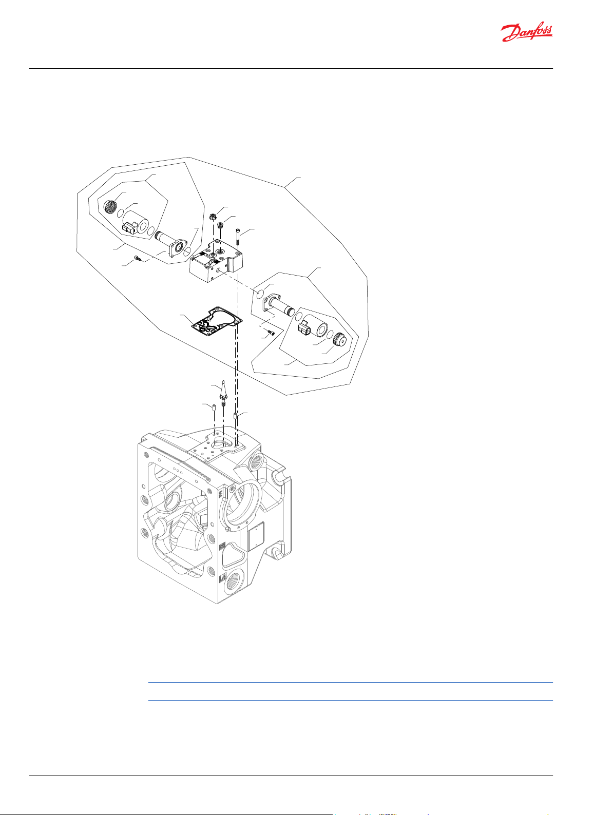
H1P control M1, M2
M1 and M2 configuration
Generic housing shown
* Included in overhaul seal kit
60 | © Danfoss | March 2022 AX152886481285en-001301
Page 61
Parts Manual
H1P 45 and 53cc
Controls
Common parts
Item Date Begin Date End Part Number Part Name Qty. per
D065 14-01 327007 Plug assembly 1
D150 14-01 11227209 Control gasket (SB-2016-033 on page 170) 1
D200 14-01 11202172 Swashplate feedback link (SB-2018-025 on page
171)
D250 14-01 505038 Screw, M6 x 45 6
D300 14-01 310979 Dowel pin 2
QD751 14-01 001131 (9004201-5000) O-ring 1
Order code: M1
QD75 14-01 11119332 Spring seat assembly 1
QD100 14-01 11141225 MDC kit 1
Order code: M2
QD75 14-01 11126847 Spring seat/neutral start switch assembly 1
QD100 14-01 11141236 MDC kit 1
Model/Kit
1
©
Danfoss | March 2022 AX152886481285en-001301 | 61
Page 62

QD100
D250
D065
*QD751
QD75
*D150
D300
D300
D200
*QD81
QD85
QD83
QD70
QD84
Parts Manual
H1P 45 and 53cc
Controls
H1P control M3, M4
M3 and M4 configuration
Generic housing shown
* Included in overhaul seal kit Q210
62 | © Danfoss | March 2022 AX152886481285en-001301
Page 63
Parts Manual
H1P 45 and 53cc
Controls
Common parts
Item Date Begin Date End Part Number Part Name Qty. per
D065 14-01 327007 Plug assembly 1
D150 14-01 11227209 Control gasket (SB-2016-033 on page 170) 1
D200 14-01 11202172 Swashplate feedback link (SB-2018-025 on page
171)
D250 14-01 505038 Screw, M6 x 45 6
D300 14-01 310979 Dowel pin 2
QD81 14-01 11152257 O-ring 1
QD84 14-01 11140393 O-ring 1
QD85 14-01 11140394 Coil nut 1
QD751 14-01 001131 (9004201-5000) O-ring 1
Order code: M3
QD70 14-01 11129916 Solenoid valve, 12v 1
QD75 14-01 11119332 Spring seat assembly 1
QD83 14-01 11136347 Coil kit, 12v 1
QD100 14-01 11218976 MDC kit, 12v, CCO 1
Model/Kit
1
Order code: M4
QD70 14-01 11129917 Solenoid valve, 24v 1
QD83 14-01 11136348 Coil kit, 24v, CCO 1
QD100 14-01 11218977 MDC kit, 24v 1
©
Danfoss | March 2022 AX152886481285en-001301 | 63
Page 64

QD100
D250
D065
*D150
D300
D300
D200
*QD81
QD85
QD83
QD70
QD84
*QD751
QD75
Parts Manual
H1P 45 and 53cc
Controls
H1P control M5, M6
M5 and M6 configuration
Generic housing shown
* Included in overhaul seal kit Q210
64 | © Danfoss | March 2022 AX152886481285en-001301
Page 65

Parts Manual
H1P 45 and 53cc
Controls
Common parts
Item Date Begin Date End Part Number Part Name Qty. per
D065 14-01 327007 Plug assembly 1
D150 14-01 11227209 Control gasket (SB-2016-033 on page 170) 1
D200 14-01 11202172 Swashplate feedback link (SB-2018-025 on page
171)
D250 14-01 505038 Screw, M6 x 45 6
D300 14-01 310979 Dowel pin 2
QD75 14-01 11126847 Spring seat/neutral start switch assembly 1
QD81 14-01 11152257 O-ring 1
QD84 14-01 11140393 O-ring 1
QD85 14-01 11140394 Coil nut 1
QD751 14-01 001131 (9004201-5000) O-ring 1
Order code: M5
QD70 14-01 11129916 Solenoid valve, 12v 1
QD83 14-01 11136347 Coil kit, 12v 1
QD100 14-01 11218978 MDC kit, 12v, neutral start switch assembly, CCO 1
Model/Kit
1
Order code: M6
QD70 14-01 11129917 Solenoid valve, 24v 1
QD83 14-01 11136348 Coil kit, 24v 1
QD100 14-01 11218979 MDC kit, 24v, neutral start switch assembly, CCO 1
©
Danfoss | March 2022 AX152886481285en-001301 | 65
Page 66

QD27
QD28
QD29
QD30
QD27
QD28
QD29
QD30
D300
D300
QD25
*QD26
D050
D050
*QD26
QD100
QD25
D250
D065
*D150
Parts Manual
H1P 45 and 53cc
Controls
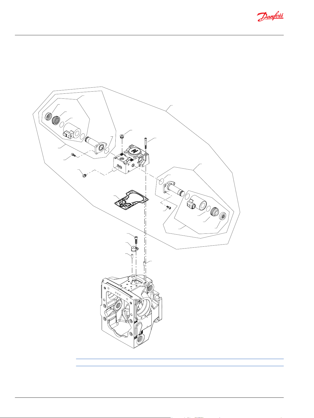
H1P control N1, N2
N1 and N2 configuration
Generic housing shown
* Included in overhaul seal kit Q210
66 | © Danfoss | March 2022 AX152886481285en-001301
Page 67

Parts Manual
H1P 45 and 53cc
Controls
Common parts
Item Date Begin Date End Part Number Part Name Qty. per
D050 16-30 716860 Screw, M5 x 12 6
D065 16-30 327007 Plug assembly 1
D150 16-30 11227209 Control gasket 1
D250 16-30 505038 Screw, M6 x 45 6
D300 16-30 310979 Dowel pin 2
QD26 16-30 11001952 O-ring 2
QD28 16-30 063172 O-ring 2
QD30 16-30 11027883 Cap 2
Order code: N1
QD25 16-30 140750 Proportional solenoid, 12v, DEUTSCH connector 2
QD27 16-30 11004698 Coil kit, 12v, DEUTSCH connector 2
QD29 16-30 11004749 Coil nut 2
QD100 16-30 11147921 NFPE control kit, 12v, manual override, DEUTSCH
connector
Model/Kit
1
Order code: N2
QD25 16-30 140751 Proportional solenoid, 24v, DEUTSCH connector 2
QD27 16-30 11004700 Coil kit, 24v, DEUTSCH connector 2
QD29 16-30 11004750 Coil nut 2
QD100 16-30 11147925 NFPE control kit, 24v, manual override, DEUTSCH
connector
1
©
Danfoss | March 2022 AX152886481285en-001301 | 67
Page 68

D300
D300
D076
*QD81
D050
*QD26
QD25
D067
QD80
QD83
QD84
QD85
D250
D050
QD25
*QD26
QD100
*D150
QD27
QD28
QD29
QD30
QD27
QD28
QD29
QD30
D200
D450
Parts Manual
H1P 45 and 53cc
Controls
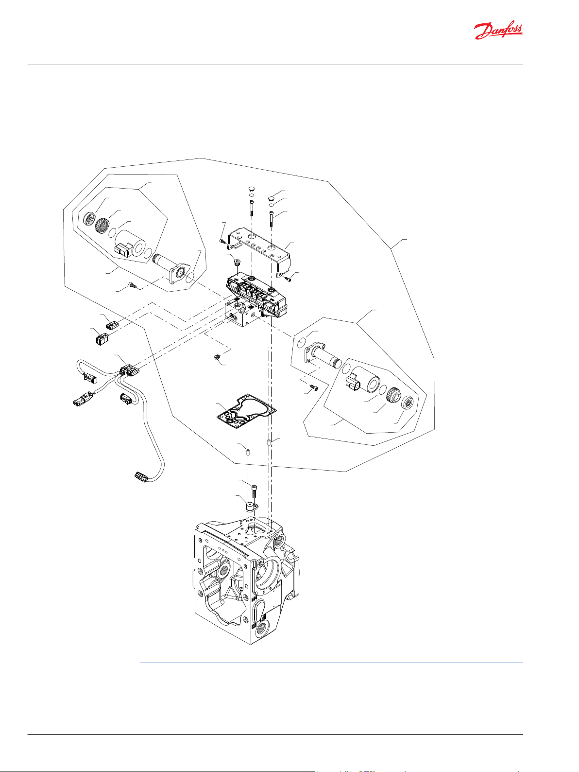
H1P control N3, N4
N3 and N4 configuration
Generic housing shown
* Included in overhaul seal kit Q210
68 | © Danfoss | March 2022 AX152886481285en-001301
Page 69

Parts Manual
H1P 45 and 53cc
Controls
Common parts
Item Date Begin Date End Part Number Part Name Qty. per
D050 16-30 716860 Screw, M5 x 12 6
D067 16-30 327007 Plug assembly 1
D076 16-30 067694 Screw, M4 x 10 2
D150 16-30 11227209 Control gasket 1
D200 16-30 141472 Screw, special 1
D250 16-30 505038 Screw, M6 x 45 6
D300 16-30 310979 Dowel pin 2
D450 16-30 11003097 Magnetic carrier 1
QD26 16-30 11001952 O-ring 2
QD28 16-30 063172 O-ring 2
QD29 16-30 11004749 Coil nut 2
QD30 16-30 11027883 Cap 2
QD81 16-30 11152257 O-ring 1
QD85 16-30 11140394 Nut 1
Model/Kit
Order code: N3
QD25 16-30 140750 Proportional solenoid, 12v 2
QD27 16-30 11004698 Coil kit, 12v, DEUTSCH connector 2
QD80 16-30 11231200 Solenoid, 12V, DEUTSCH connector 1
QD83 16-30 11232757 Coil kit, 12V, DEUTSCH connector 1
QD84 16-30 11232752 O-ring 1
QD100 16-30 11147920 NFPE control kit, 12v, CCO 1
Order code: N4
QD25 16-30 140751 Proportional solenoid, 24v 2
QD27 16-30 11004700 Coil kit, 24v, DEUTSCH connector 2
QD80 16-30 11231201 Solenoid, 24V, DEUTSCH connector 1
QD83 16-30 11232697 Coil kit, 24V, DEUTSCH connector 1
QD84 16-30 11232752 O-ring 1
QD100 16-30 11147924 NFPE control kit, 24v, CCO 1
©
Danfoss | March 2022 AX152886481285en-001301 | 69
Page 70

QD100
D250
*D150
D300
D300
D200
D450
D050
QD25
*QD26
QD27
QD28
QD29
QD30
D050
*QD26
QD25
QD27
QD28
QD29
QD30
Parts Manual
H1P 45 and 53cc
Controls
H1P control N5, N6
N5 and N6 configuration
Generic housing shown
* Included in overhaul seal kit Q210
70 | © Danfoss | March 2022 AX152886481285en-001301
Page 71

Parts Manual
H1P 45 and 53cc
Controls
Common parts
Item Date Begin Date End Part Number Part Name Qty. per
D050 16-30 716860 Screw, M5 x 12 6
D150 16-30 11227209 Control gasket 1
D200 16-30 141472 Screw, special 1
D250 16-30 505038 Screw, M6 x 45 6
D300 16-30 310979 Dowel pin 2
D450 16-30 11003097 Magnetic carrier 1
QD26 16-30 11001952 O-ring 2
QD28 16-30 063172 O-ring 2
QD29 16-30 11004749 Coil nut 2
QD30 16-30 11027883 Cap 2
Order code: N5
QD25 16-30 140750 Proportional solenoid, 12v 2
QD27 16-30 11004698 Coil kit, 12v, DEUTSCH connector 2
QD100 16-30 11147918 NFPE control kit, 12v, manual override 1
Model/Kit
Order code: N6
QD25 16-30 140751 Proportional solenoid, 24v 2
QD27 16-30 11004700 Coil kit, 24v, DEUTSCH connector 2
QD100 16-30 11147922 NFPE control kit, 24v, manual override 1
©
Danfoss | March 2022 AX152886481285en-001301 | 71
Page 72

D300
D300
D076
*QD81
D067
QD80
QD83
QD84
QD85
D250
QD100
*D150
D050
QD25
*QD26
QD27
QD28
QD29
QD30
D050
*QD26
QD25
QD27
QD28
QD29
QD30
D065
Parts Manual
H1P 45 and 53cc
Controls
H1P control N7, N8
N7 and N8 configuration
Generic housing shown
* Included in overhaul seal kit Q210
72 | © Danfoss | March 2022 AX152886481285en-001301
Page 73

Parts Manual
H1P 45 and 53cc
Controls
Common parts
Item Date Begin Date End Part Number Part Name Qty. per
D050 16-30 716860 Screw, M5 x 12 6
D067 16-30 327007 Plug assembly 1
D076 16-30 067694 Screw, M4 x 10 1
D150 16-30 11227209 Control gasket 1
D250 16-30 505038 Screw, M6 x 45 6
D300 16-30 310979 Dowel pin 2
QD26 16-30 11001952 O-ring 2
QD28 16-30 063172 O-ring 2
QD30 16-30 11027883 Cap 2
QD81 16-30 11152257 O-ring 1
QD85 16-30 11140394 Nut 1
Order code: N7
QD25 16-30 140750 Proportional solenoid, 12v 2
QD27 16-30 11004698 Coil kit, 12v, DEUTSCH connector 2
QD29 16-30 11004749 Coil nut 2
QD80 16-30 11231200 Solenoid, 12V, DEUTSCH connector 1
QD83 16-30 11232757 Coil kit, 12V, DEUTSCH connector 1
QD84 16-30 11232752 O-ring 1
QD100 16-30 11147919 NFPE control kit, 12v, CCO 1
Model/Kit
Order code: N8
QD25 16-30 140751 Proportional solenoid, 24v 2
QD27 16-30 11004700 Coil kit, 24v, DEUTSCH connector 2
QD29 16-30 11004750 Coil nut 2
QD80 16-30 11231201 Solenoid, 24V, DEUTSCH connector 1
QD83 16-30 11232697 Coil kit, 24V, DEUTSCH connector 1
QD84 16-30 11232752 O-ring 1
QD100 16-30 11147923 NFPE control kit, 24v, CCO 1
©
Danfoss | March 2022 AX152886481285en-001301 | 73
Page 74

*D150
QD100
D250
D550
D550
D300
D300
D200
D300
D300
*D150
QD100
D250
D550
D550
(ND)(ND)
(NN)(NN)
Parts Manual
H1P 45 and 53cc
Controls
H1P control ND, NN
ND and NN configuration
Generic housing shown
* Included in overhaul seal kit Q210
74 | © Danfoss | March 2022 AX152886481285en-001301
Page 75

Parts Manual
H1P 45 and 53cc
Controls
Order code: ND
Item Date Begin Date End Part Number Part Name Qty. per
D150 16-02 11227209 Control gasket 1
D200 16-02 11202172 Swashplate feedback link 1
D250 16-02 505038 Screw, M6 x 45 6
D300 16-02 310979 Dowel pin 2
D550 16-02 140644 Plug assembly 2
QD100 16-02 11121984 Control cover kit 1
Order code: NN
D150 14-01 11227209 Control gasket (SB-2016-033 on page 170) 1
D250 14-01 505038 Screw, M6 x 45 6
D300 14-01 310979 Dowel pin 2
D550 14-01 140644 Plug assembly 2
QD100 14-01 11121984 Control cover kit 1
Model/Kit
©
Danfoss | March 2022 AX152886481285en-001301 | 75
Page 76

D300
D300
D250
*D612
QD100
D655
D660
QD25
*QD26
QD27
D050
QD28
QD29
QD30
D050
QD27
*QD26
QD25
QD28
QD29
QD30
D665
D674
D674
D672
*D150
*D611
Parts Manual
H1P 45 and 53cc
Controls
H1P control P5
P5 configuration
Generic housing shown
* Included in overhaul kit Q210
76 | © Danfoss | March 2022 AX152886481285en-001301
Page 77

Parts Manual
H1P 45 and 53cc
Controls
Order code: P5
Item Date Begin Date End Part Number Part Name Qty. per
D050 17-15 716860 Screw, M5 x 12 6
D150 17-15 11227209 Control gasket 1
D250 17-15 505038 Screw, M6 x 45 6
D300 17-15 11036469 Dowel pin 2
D611 17-15 21-12 11066774 O-ring (SB-2021-014 on page 173) 2
D611 21-13 11225703 O-ring 2
D612 17-15 21-12 11003126 Plug (SB-2021-014 on page 173) 2
D612 21-13 11223708 Plug 2
D655 17-15 11084827 Blank, connector DTM 06-3S 1
D660 17-15 11084822 Blank, connector DTM 06-6S 1
D665 17-15 11084827 Blank, connector DTM 06-3S 1
D672 17-15 11151875 Protection 1
D674 17-15 716860 Screw, M5 x 12 2
QD25 17-15 140750 Proportional solenoid, 12 volt 2
QD26 17-15 11001952 O-ring 2
QD27 17-15 11004698 Coil kit, 12v, DEUTSCH connector 2
QD28 17-15 063172 O-ring 2
QD29 17-15 11004749 Coil nut 2
QD30 17-15 11027883 Cap 2
QD100 17-15 11232768 Automotive control kit, 12v, manual override 1
Model/Kit
©
Danfoss | March 2022 AX152886481285en-001301 | 77
Page 78
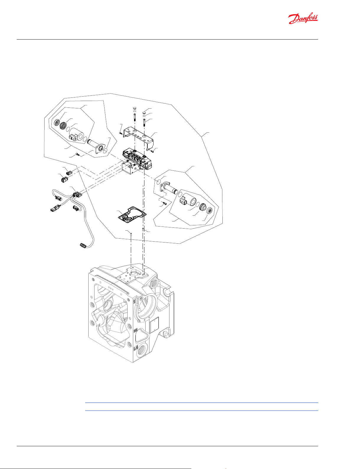
D300
D300
D250
*D612
QD100
D655
D660
*D611
QD25
*QD26
QD27
D050
QD28
QD29
QD30
D050
QD27
*QD26
QD25
QD28
QD29
QD30
D640
D674
D674
D672
*D150
Parts Manual
H1P 45 and 53cc
Controls
H1P control P6, P7
P6 and P7 configuration
Generic housing shown
* Included in overhaul seal kit Q210
78 | © Danfoss | March 2022 AX152886481285en-001301
Page 79

Parts Manual
H1P 45 and 53cc
Controls
Common parts
Item Date Begin Date End Part Number Part Name Qty. per
D050 16-30 716860 Screw, M5 x 12 6
D150 16-30 11227209 Control gasket 1
D250 16-30 505038 Screw, M6 x 45 6
D300 16-30 11036469 Dowel pin 2
D611 16-30 21-12 11066774 O-ring (SB-2021-014 on page 173) 2
D611 21-13 11225703 O-ring 2
D612 16-30 21-12 11003126 Plug (SB-2021-014 on page 173) 2
D612 21-13 11223708 Plug 2
D640 16-30 11023348 AC wiring harness 1
D655 16-30 11084827 Blank, connector DTM 06-3S 1
D660 16-30 11084822 Blank, connector DTM 06-6S 1
D672 16-30 11151875 Protection 1
D674 16-30 716860 Screw, M5 x 12 2
QD26 16-30 11001952 O-ring 2
QD28 16-30 063172 O-ring 2
QD29 16-30 11004749 Coil nut 2
QD30 16-30 11027883 Cap 2
Model/Kit
Order code: P6
QD25 16-30 140750 Proportional solenoid, 12 volt 2
QD27 16-30 11004698 Coil kit, 12v, DEUTSCH connector 2
QD100 16-30 11232768 Automotive control kit, 12v, manual override 1
Order code: P7
QD25 16-30 140751 Proportional solenoid, 24 volt 2
QD27 16-30 11004700 Coil kit, 24v, DEUTSCH connector 2
QD100 16-30 11232769 Automotive control kit, 24v, manual override 1
©
Danfoss | March 2022 AX152886481285en-001301 | 79
Page 80

D300
D300
D250
*D612
QD100
D655
D660
*D611
QD25
*QD26
QD27
D050
QD28
QD29
QD30
D050
QD27
*QD26
QD25
QD28
QD29
QD30
D640
D674
D674
D672
*D150
D200
D450
Parts Manual
H1P 45 and 53cc
Controls
H1P control P8, P9
P8 and P9 configuration
Generic housing shown
* Included in overhaul seal kit Q210
80 | © Danfoss | March 2022 AX152886481285en-001301
Page 81

Parts Manual
H1P 45 and 53cc
Controls
Common parts
Item Date Begin Date End Part Number Part Name Qty. per
D050 16-30 716860 Screw, M5 x 12 6
D150 16-30 11227209 Control gasket 1
D200 16-30 141472 Screw, special 1
D250 16-30 505038 Screw, M6 x 45 6
D300 16-30 11036469 Dowel pin 2
D450 16-30 11003097 Magnetic carrier 1
D611 16-30 21-12 11066774 O-ring (SB-2021-014 on page 173) 2
D611 21-13 11225703 O-ring 2
D612 16-30 21-12 11003126 Plug (SB-2021-014 on page 173) 2
D612 21-13 11223708 Plug 2
D640 16-30 11023348 AC wiring harness 1
D655 16-30 11084827 Blank, connector DTM 06-3S 1
D660 16-30 11084822 Blank, connector DTM 06-6S 1
D672 16-30 11151875 Protection 1
D674 16-30 716860 Screw, M5 x 12 2
QD26 16-30 11001952 O-ring 2
QD28 16-30 063172 O-ring 2
QD30 16-30 11027883 Cap 2
Model/Kit
Order code: P8
QD25 16-30 140750 Proportional solenoid, 12 volt 2
QD27 16-30 11004698 Coil kit, 12v, DEUTSCH connector 2
QD29 16-30 11004749 Coil nut 2
QD100 16-30 11232770 Automotive control kit, 12v, manual override 1
Order code: P9
QD25 16-30 140751 Proportional solenoid, 24 volt 2
QD27 16-30 11004700 Coil kit, 24v, DEUTSCH connector 2
QD29 16-30 11004750 Coil nut 2
QD100 16-30 11232771 Automotive control kit, 24v, manual override 1
©
Danfoss | March 2022 AX152886481285en-001301 | 81
Page 82
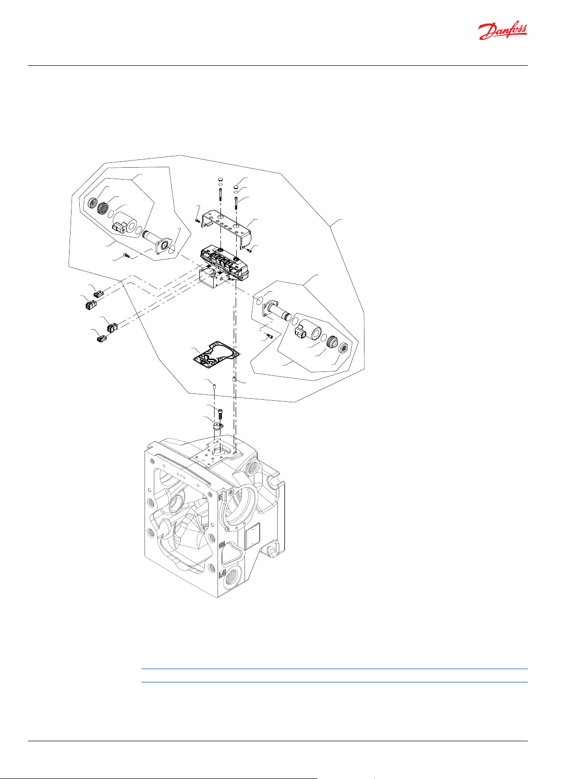
D300
D300
D250
*D612
QD100
D655
D660
*D611
QD25
*QD26
QD27
D050
QD28
QD29
QD30
D050
QD27
*QD26
QD25
QD28
QD29
QD30
D640
D674
D674
D672
*D150
D200
D450
D665
Parts Manual
H1P 45 and 53cc
Controls
H1P control R3
R3 configuration
Generic housing shown
* Included in overhaul seal kit Q210
82 | © Danfoss | March 2022 AX152886481285en-001301
Page 83

Parts Manual
H1P 45 and 53cc
Controls
Order code: R3
Item Date Begin Date End Part Number Part Name Qty. per
D050 16-17 716860 Screw, M5 x 12 6
D150 16-17 11227209 Control gasket 1
D200 16-17 141472 Screw, special 1
D250 16-17 505038 Screw, M6 x 45 6
D300 16-17 11036469 Dowel pin 2
D450 16-17 11003097 Magnetic carrier 1
D611 16-17 21-12 11066774 O-ring (SB-2021-014 on page 173) 2
D611 21-13 11225703 O-ring 2
D612 16-17 21-12 11003126 Plug (SB-2021-014 on page 173) 2
D612 21-13 11223708 Plug 2
D640 16-17 11084822 Blank, connector DTM 06-6S 1
D655 16-17 11084827 Blank, connector DTM 06-3S 1
D660 16-17 11084822 Blank, connector DTM 06-6S 1
D665 16-17 11084827 Blank, connector DTM 06-3S 1
D672 16-17 11151875 Protection 1
D674 16-17 716860 Screw, M5 x 12 2
QD25 16-17 140751 Proportional solenoid, 24 volt 2
QD26 16-17 11001952 O-ring 2
QD27 16-17 11004700 Coil kit, 24v, DEUTSCH connector 2
QD28 16-17 063172 O-ring 2
QD29 16-17 11004750 Coil nut 2
QD30 16-17 11027883 Cap 2
QD100 16-17 11232769 Automotive control kit, 24v, manual override 1
Model/Kit
©
Danfoss | March 2022 AX152886481285en-001301 | 83
Page 84
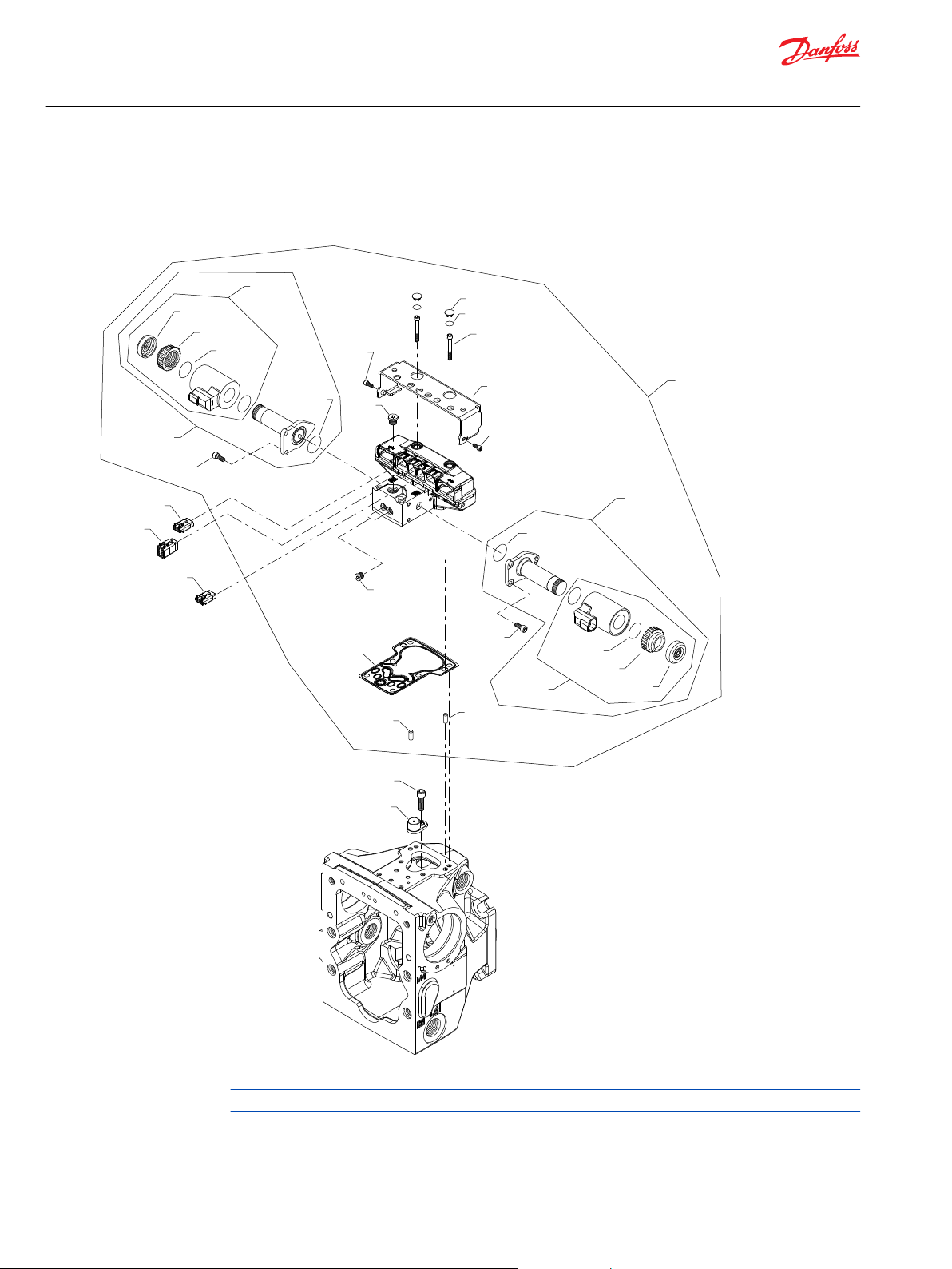
D200
D450
D300
D300
D250
*D612
QD100
D655
D660
*D611
D067
D055
QD25
*QD26
QD27
D050
QD28
QD29
QD30
D050
QD27
*QD26
QD25
QD28
QD29
QD30
D674
D674
D672
*D150
D665
Parts Manual
H1P 45 and 53cc
Controls
H1P control R4
R4 configuration
Generic housing shown
* Included in overhaul seal kit Q210
84 | © Danfoss | March 2022 AX152886481285en-001301
Page 85
Parts Manual
H1P 45 and 53cc
Controls
Order code: R4
Item Date Begin Date End Part Number Part Name Qty. per
D050 17-15 716860 Screw, M5 x 12 6
D150 17-15 11227209 Control gasket 1
D200 17-15 141472 Screw, special 1
D250 17-15 505038 Screw, M6 x 45 6
D300 17-15 11036469 Dowel pin 2
D450 17-15 11003097 Magnetic carrier 1
D611 17-15 21-12 11066774 O-ring (SB-2021-014 on page 173) 2
D611 21-13 11225703 O-ring 2
D612 17-15 21-12 11003126 Plug (SB-2021-014 on page 173) 2
D612 21-13 11223708 Plug 2
D655 17-15 11084827 Blank, connector DTM 06-3S 1
D660 17-15 11084822 Blank, connector DTM 06-6S 1
D665 17-15 11084827 Blank, connector DTM 06-3S 1
D672 17-15 11151875 Protection 1
D674 17-15 716860 Screw, M5 x 12 2
QD25 17-15 140750 Proportional solenoid, 12 volt 2
QD26 17-15 11001952 O-ring 2
QD27 17-15 11004698 Coil kit, 12v, DEUTSCH connector 2
QD28 17-15 063172 O-ring 2
QD29 17-15 11004749 Coil nut 2
QD30 17-15 11027883 Cap 2
QD100 17-15 11232770 Automotive control kit, 12v, manual override 1
Model/Kit
©
Danfoss | March 2022 AX152886481285en-001301 | 85
Page 86

D300
D300
D250
*D612
QD100
D655
D660
*D611
QD25
*QD26
QD27
D050
QD28
QD29
QD30
D050
QD27
*QD26
QD25
QD28
QD29
QD30
D640
D674
D674
D672
*D150
Parts Manual
H1P 45 and 53cc
Controls
H1P control T6, T7
Parts configuration
Generic housing shown
* Included in overhaul seal kit Q210
86 | © Danfoss | March 2022 AX152886481285en-001301
Page 87

Parts Manual
H1P 45 and 53cc
Controls
Order code: T6
Item Date Begin Date End Part Number Part Name Qty. per
D050 18-15 716860 Screw, M5 x 12 6
D150 18-15 11227209 Control Gasket 1
D250 18-15 505038 Screw, M6 x 45 6
D300 18-15 11036469 Dowel pin 2
D611 18-15 21-12 11066774 O-ring (SB-2021-014 on page 173) 1
D611 21-13 11225703 O-ring 2
D612 18-15 21-12 11003126 Plug (SB-2021-014 on page 173) 2
D612 21-13 11223708 Plug 2
D640 18-15 11197432 AC wiring harness 1
D655 18-15 11084827 Blank, connector DTM 06-3S 1
D660 18-15 11084822 Blank, connector DTM 06-6S 1
D665 18-15 11084827 Blank, connector DTM 06-3S 1
D672 18-15 11151875 Protection 1
D674 18-15 716860 Screw, M5 x 12 2
QD100 18-15 11232768 Automotive control kit, 12v, manual override 1
QD25 18-15 140750 Proportional solenoid, 12v 2
QD26 18-15 11001952 O-ring 2
QD27 18-15 11004698 Coil kit, 12v, DEUTSCH connector 2
QD28 18-15 063172 O-ring 2
QD29 18-15 11004749 Coil nut 2
QD30 18-15 11027883 Cap 2
Model/Kit
Order code: T7
D050 18-15 716860 Screw, M5 x 12 6
D150 18-15 11227209 Control gasket 1
D250 18-15 505038 Screw, M6 x 45 6
D300 18-15 11036469 Dowel pin 2
D611 18-15 21-12 11066774 O-ring (SB-2021-014 on page 173) 1
D611 21-13 11225703 O-ring 2
D612 18-15 21-12 11003126 Plug (SB-2021-014 on page 173) 2
D612 21-13 11223708 Plug 2
D640 18-15 11197432 AC wiring harness 1
D655 18-15 11084827 Blank, connector DTM 06-3S 1
D660 18-15 11084822 Blank, connector DTM 06-6S 1
D665 18-15 11084827 Blank, connector DTM 06-3S 1
D672 18-15 11151875 Protection 1
D674 18-15 716860 Screw, M5 x 12 2
QD100 18-15 11232769 Automotive control kit, 24v, manual override 1
QD25 18-15 140751 Proportional solenoid, 24v 2
QD26 18-15 11001952 O-ring 2
QD27 18-15 11004700 Coil kit, 24v, DEUTSCH connector 2
QD28 18-15 063172 O-ring 2
QD29 18-15 11004750 Coil nut 2
QD30 18-15 11027883 Cap 2
©
Danfoss | March 2022 AX152886481285en-001301 | 87
Page 88

D300
D300
D250
*D612
QD100
D655
D660
*D611
QD25
*QD26
QD27
D050
QD28
QD29
QD30
D050
QD27
*QD26
QD25
QD28
QD29
QD30
D640
D674
D674
D672
*D150
D665
D200
D450
Parts Manual
H1P 45 and 53cc
Controls
H1P control T8, T9
Parts configuration
Generic housing shown
* Included in overhaul seal kit Q210
88 | © Danfoss | March 2022 AX152886481285en-001301
Page 89

Parts Manual
H1P 45 and 53cc
Controls
Order code: T8
Item Date Begin Date End Part Number Part Name Qty. per
D050 18-12 716860 Screw, M5 x 12 6
D150 18-12 11227209 Control gasket 1
D200 18-12 141472 Screw, special 1
D250 18-12 505038 Screw, M6 x 45 6
D300 18-12 11036469 Dowel pin 2
D450 18-12 11003097 Magnet carrier 1
D611 18-12 21-12 11066774 O-ring (SB-2021-014 on page 173) 1
D611 21-13 11225703 O-ring 2
D612 18-12 21-12 11003126 Plug (SB-2021-014 on page 173) 2
D612 21-13 11223708 Plug 2
D640 18-12 11197432 AC wiring harness 1
D655 18-12 11084827 Blank, connector DTM 06-3S 1
D660 18-12 11084822 Blank, connector DTM 06-6S 1
D665 18-12 11084827 Blank, connector DTM 06-3S 1
D672 18-12 11151875 Protection 1
D674 18-12 716860 Screw, M5 x 12 2
QD100 18-12 11232770 Automotive control kit, 12v, manual override 1
QD25 18-12 140750 Proportional solenoid, 12v 2
QD26 18-12 11001952 O-ring 2
QD27 18-12 11004698 Coil kit, 12v, DEUTSCH connector 2
QD28 18-12 063172 O-ring 2
QD29 18-12 11004749 Coil nut 2
QD30 18-12 11027883 Cap 2
Model/Kit
Order code: T9
D150 18-12 11227209 Control gasket 1
D200 18-12 141472 Screw, special 1
D250 18-12 505038 Screw, M6 x 45 6
D450 18-12 11003097 Magnet carrier 1
D610 18-12 11000467 Plug assembly 2
D611 18-12 11066774 O-ring 1
D640 18-12 11197432 AC wiring harness 1
D655 18-12 11084827 Blank, connector DTM 06-3S 1
D660 18-12 11084822 Blank, connector DTM 06-6S 1
D665 18-15 11084827 Blank, connector DTM 06-3S 1
D672 18-12 11151875 Protection 1
D674 18-12 716860 Screw, M5 x 12 2
QD100 18-12 11232771 Automotive control kit, 24v, manual override 1
QD25 18-12 140751 Proportional solenoid, 24v 2
QD26 18-12 11001952 O-ring 2
QD27 18-12 11004700 Coil kit, 24v, DEUTSCH connector 2
QD28 18-12 063172 O-ring 2
QD29 18-12 11004750 Coil nut 2
QD30 18-12 11027883 Cap 2
©
Danfoss | March 2022 AX152886481285en-001301 | 89
Page 90

D665
D300
D300
D250
*D612
QD100
D655
D660
*D611
QD25
*QD26
QD27
D050
QD28
QD29
QD30
D050
QD27
*QD26
QD25
QD28
QD29
QD30
D640
D674
D674
D672
*D150
Parts Manual
H1P 45 and 53cc
Controls
H1P control U1, U2
Parts configuration
Generic housing shown
* Included in overhaul seal kit Q210
90 | © Danfoss | March 2022 AX152886481285en-001301
Page 91

Parts Manual
H1P 45 and 53cc
Controls
Common parts
Item Date Begin Date End Part Number Part Number Qty. per
D050 18-10 716860 Screw, M5 x 12 6
D150 18-10 11227209 Control gasket 1
D250 18-10 505038 Screw, M6 x 45 6
D300 18-10 11036469 Dowel pin 2
D611 18-10 21-12 11066774 O-ring (SB-2021-014 on page 173) 1
D611 21-13 11225703 O-ring 2
D612 18-10 21-12 11003126 Plug (SB-2021-014 on page 173) 2
D612 21-13 11223708 Plug 2
D640 18-10 11197432 AC wiring harness 1
D655 18-10 11084827 Connector DTM 06-3s 1
D660 18-10 11084822 Connector DTM 06-6s 1
D665 18-10 11084827 Connector DTM 06-3s 1
D672 18-10 11151875 Protection 1
D674 18-10 716860 Screw, M5 x 12 2
QD26 18-10 11001952 O-ring 2
QD28 18-10 063172 O-ring 2
QD30 18-10 11027883 Cap 2
Model/Kit
Order code: U1
QD100 18-10 11232792 Service control kit, 12v 1
QD25 18-10 140750 Proportional solenoid, 12v 2
QD27 18-10 11004698 Coil kit, 12v, DEUTSCH connector 2
QD29 18-10 11004749 Coil nut 2
Order code: U2
QD100 16-29 11232793 Automotive control kit, 24V, manual override 1
QD25 16-29 140751 Proportional solenoid, 24V 2
QD27 16-29 11004700 Coil kit, 24V, DEUTSCH connector 2
QD29 16-29 11004750 Coil nut 2
©
Danfoss | March 2022 AX152886481285en-001301 | 91
Page 92
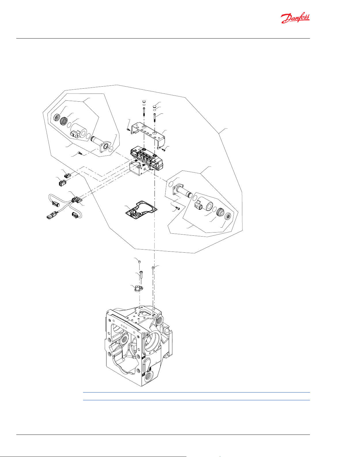
D300
D300
D250
*D612
QD100
D655
D660
*D611
QD25
*QD26
QD27
D050
QD28
QD29
QD30
D050
QD27
*QD26
QD25
QD28
QD29
QD30
D640
D674
D674
D672
*D150
D665
D200
D450
Parts Manual
H1P 45 and 53cc
Controls
H1P control U3, U4
Parts configuration
Generic housing shown
* Included in overhaul seal kit Q210
92 | © Danfoss | March 2022 AX152886481285en-001301
Page 93
Parts Manual
H1P 45 and 53cc
Controls
Common parts
Item Date Begin Date End Part Number Part Name Qty. per
D050 16-29 716860 Screw, M5x12 6
D150 16-29 11227209 Control gasket 1
D200 16-29 141472 Screw, M8x1x30 1
D250 16-29 505038 Screw, M6x45 6
D300 16-29 11036469 Dowel pin 2
D450 16-29 11003097 Magnet carrier 1
D611 16-29 21-12 11066774 O-ring (SB-2021-014 on page 173) 1
D611 21-13 11225703 O-ring 2
D612 16-29 21-12 11003126 Plug (SB-2021-014 on page 173) 2
D612 21-13 11223708 Plug 2
D640 16-29 11197432 AC wiring harness 1
D655 16-29 11084827 Connector DTM06-3S 1
D660 16-29 11084822 Connector DTM06-6S 1
D665 16-29 11084827 Connector DTM06-3S 1
D672 16-29 11151875 Protection 1
D674 16-29 716860 Screw, M5x12 2
QD26 16-29 11001952 O-ring 2
QD28 16-29 063172 O-ring 2
QD30 16-29 11027883 Cap 2
Model/Kit
Order code: U3
QD100 16-29 11180763 Automotive control kit, 12v, manual override 1
QD25 16-29 140750 Proportional solenoid, 12V 2
QD27 16-29 11004698 Coil kit, 12v, DEUTSCH connector 2
QD29 16-29 11004749 Coil nut 2
Order code: U4
QD100 16-29 11180765 Automotive control kit, 24V, manual override 1
QD25 16-29 140751 Proportional solenoid, 24V 2
QD27 16-29 11004700 Coil kit, 24V, DEUTSCH connector 2
QD29 16-29 11004750 Coil nut 2
©
Danfoss | March 2022 AX152886481285en-001301 | 93
Page 94

Design prior
to 07-23
E100
E015
*E025
*E025
*E020
*E020
*E250
E350
E300
E200
*E550
E450
*E250
E200
E300
E350
E350
E300
E150
*E250
*E250
E350
E300
E150
*E500
E400
E300
E150
E300
E150
(B & D)
(C)
(B & D)
(C)
Parts Manual
H1P 45 and 53cc
Displacement limitation
H1P 45/53 displacement limitation B-D
Parts configuration
* Included in overhaul seal kit Q210
94 | © Danfoss | March 2022 AX152886481285en-001301
Page 95

Parts Manual
H1P 45 and 53cc
Displacement limitation
Order code: B
Item Date Begin Date End Part Number Part Name Qty. per
E015 12-21 11014805 Slider block (SB-2011-020 on page 167) 1
E015 07-19 12-20 141939 Slider block 1
E020 07-19 5000732 O-ring 2
E025 07-19 11028034 Piston seal ring (SB-2007-026 on page 154) 2
E100 12-21 11094107 Servo piston assembly (SB-2011-020 on page
167)
E100 07-19 12-20 11098278 Servo piston assembly replacement kit 1
E150 07-19 11059648 Servo cylinder assembly, adjustable (SB-2007-004
on page 152)
E200 07-19 11059648 Servo cylinder assembly, adjustable (SB-2007-004
on page 152)
E250 07-19 5000709 O-ring 2
E300 07-23 11013910 Locking plate 2
E300 07-19 07-22 141940 Locking plate (SB-2007-004 on page 152) 2
E350 07-19 508438 Screw, M6 x 12 4
E400 07-19 5000747 Set screw, M8 x 45 1
E450 07-19 5000747 Set screw, M8 x 45 1
E500 07-19 505412 (9003509-0008) Seal nut, M8 1
E550 07-19 505412 (9003509-0008) Seal nut, M8 1
Model/Kit
1
1
1
Order code: C
E015 12-21 11014805 Slider block (SB-2011-020 on page 167) 1
E015 07-19 12-20 141939 Slider block 1
E020 07-19 5000732 O-ring 2
E025 07-19 11028034 Piston seal ring (SB-2007-026 on page 154) 2
E100 12-21 11094283 Servo piston assembly, nested spring
(SB-2011-020 on page 167)
E100 07-19 12-20 11098279 Servo piston assembly replacement kit 1
E150 07-30 11059647 Servo cylinder assembly (SB-2007-004 on page
152)
E200 07-30 11059647 Servo cylinder assembly (SB-2007-004 on page
152)
E250 07-19 5000709 O-ring 2
E300 07-30 11013910 Locking plate 2
E300 07-19 07-29 141940 Locking plate (SB-2007-004 on page 152) 2
E350 07-19 508438 Screw, M6 x 12 4
Parts continue to the next 2 pages.
1
1
1
©
Danfoss | March 2022 AX152886481285en-001301 | 95
Page 96

Design prior
to 07-23
E100
E015
*E025
*E025
*E020
*E020
*E250
E350
E300
E200
*E550
E450
*E250
E200
E300
E350
E350
E300
E150
*E250
*E250
E350
E300
E150
*E500
E400
E300
E150
E300
E150
(B & D)
(C)
(B & D)
(C)
Parts Manual
H1P 45 and 53cc
Displacement limitation
Parts configuration
* Included in overhaul seal kit Q210
96 | © Danfoss | March 2022 AX152886481285en-001301
Page 97
Parts Manual
H1P 45 and 53cc
Displacement limitation
Order code: D
Item Date Begin Date End Part Number Part Name Qty. per
E015 12-21 11014805 Slider block (SB-2011-020 on page 167) 1
E015 07-19 12-20 141939 Slider block 1
E020 07-19 5000732 O-ring 2
E025 07-19 11028034 Piston seal ring (SB-2007-026 on page 154) 2
E100 12-21 11094283 Servo piston assembly, nested spring
(SB-2011-020 on page 167)
E100 07-19 12-20 11098279 Servo piston assembly replacement kit 1
E150 07-19 11059648 Servo cylinder assembly, adjustable (SB-2007-004
on page 152)
E200 07-19 11059648 Servo cylinder assembly, adjustable (SB-2007-004
on page 152)
E250 07-19 5000709 O-ring 2
E300 07-23 11013910 Locking plate 2
E300 07-19 07-22 141940 Locking plate (SB-2007-004 on page 152) 2
E350 07-19 508438 Screw, M6 x 12 4
E400 07-19 5000747 Set screw, M8 x 45 1
E450 07-19 5000747 Set screw, M8 x 45 1
E500 07-19 505412 (9003509-0008) Seal nut, M8 1
E550 07-19 505412 (9003509-0008) Seal nut, M8 1
Model/Kit
1
1
1
©
Danfoss | March 2022 AX152886481285en-001301 | 97
Page 98

E300
E150
Design prior
to 07-23
E100
E015
*E025
*E025
*E020
*E020
*E250
E350
E300
E200
*E550
E450
*E250
E200
E300
E350
E350
E300
E150
*E250
(E)
(N)
(E & N)
Parts Manual
H1P 45 and 53cc
Displacement limitation
H1P 45/53 displacement limitation E-N
Parts configuration
Generic housing shown
* Included in overhaul seal kit Q210
98 | © Danfoss | March 2022 AX152886481285en-001301
Page 99
Parts Manual
H1P 45 and 53cc
Displacement limitation
Order code: E
Item Date Begin Date End Part Number Part Name Qty. per
E015 15-07 11014805 Slider block 1
E020 15-07 5000732 O-ring 2
E025 15-07 11028034 Piston seal ring 2
E100 15-07 11094283 Servo piston assembly, nested spring 1
E150 15-07 11059647 Servo cylinder assembly 1
E200 15-07 11059648 Servo cylinder assembly, adjustable 1
E250 15-07 5000709 O-ring 2
E300 15-07 11013910 Locking plate 2
E350 15-07 508438 Screw, M6 x 12 4
E450 15-07 719401 Set screw, M8 x 50 1
E550 15-07 505412 (9003509-0008) Seal nut, M8 1
Order code: N
E015 12-21 11014805 Slider block (SB-2011-020 on page 167) 1
E015 07-19 12-20 141939 Slider block 1
E020 07-19 5000732 O-ring 2
E025 07-19 11028034 Piston seal ring (SB-2007-026 on page 154) 2
E100 12-21 11094107 Servo piston assembly (SB-2011-020 on page
167)
E100 07-19 12-20 11098278 Servo piston assembly replacement kit 1
E150 07-30 11059647 Servo cylinder assembly (SB-2007-004 on page
152)
E200 07-30 11059647 Servo cylinder assembly (SB-2007-004 on page
152)
E250 07-19 5000709 O-ring 2
E300 07-30 11013910 Locking plate 2
E300 07-19 07-29 141940 Locking plate (SB-2007-004 on page 152) 2
E350 07-19 508438 Screw 4
Model/Kit
1
1
1
©
Danfoss | March 2022 AX152886481285en-001301 | 99
Page 100

F00B
F00A
F00P
F00T
F00T
F00T
F00T
F00T
F00T
F00P
F00B
F00A
(C1, C2, D8, E1)
(C6 & C7)(C6 & C7)
(C8, C9, D1, D2 & D3)(C8, C9, D1, D2 & D3)
(D4 & D5)(D4 & D5)
Parts Manual
H1P 45 and 53cc
Orifice
H1P 45/53 orifice
Parts configuration
Generic housings and control shown.
* Included in overhaul seal kit Q210
100 | © Danfoss | March 2022 AX152886481285en-001301
 Loading...