

Page 1
Technical Information
H1P 045/053
Axial Piston Single Pumps
www.danfoss.com
Page 2

Technical Information
H1P 045/053 Axial Piston Single Pumps
Revision history Table of revisions
Date Changed Rev
December 2021 Added HDC control 1501
April 2021 Added missing Jxx pressure protection settings to model code 1401
September 2020 corrected dimensions and mounting screws information 1306
June 2020 Added caution note to mounting dimensions 1305
April 2020 Corrected swash plate angle sensor connector and CCO connector descriptions 1304
February 2020 Added NFPE control options and changed document number from BC00000059 1303
June 2019 Major revision. 1201
May 2018 Major revision. 1101
May 2017 NFPE gen. 3 changes. 1001
November 2015 Master Model Code changes. 0900
2010-2014 Various changes. BA-IA
Jul 2009 First edition AA
2 | © Danfoss | December 2021 BC152886483105en-001501
Page 3

Technical Information
H1P 045/053 Axial Piston Single Pumps
Contents
Technical Specifications
H1 Pumps General Specification.................................................................................................................................................6
H1P 045/053 Technical Data........................................................................................................................................................ 6
H1P 045/053 Operating Parameters .........................................................................................................................................7
Fluid Specification............................................................................................................................................................................8
H1P 045/053 Mounting Flange Loads ..................................................................................................................................... 9
Bearing Life and External Radial Shaft Loads.......................................................................................................................10
Charge pump...................................................................................................................................................................................11
Charge Pump Selection..........................................................................................................................................................11
12 cm³ Charge Pump – Flow and Power Curves........................................................................................................... 11
Master Model Code
Displacement, A—Rotation, B—Product Version, Z—Port Configuration...............................................................12
D—Controls..................................................................................................................................................................................... 13
Electronic Displacement Controls...................................................................................................................................... 13
Fan Drive Controls....................................................................................................................................................................13
Forward-Neutral-Reverse (FNR) Controls.........................................................................................................................13
Non-Feedback Proportional Electric (NFPE) Controls................................................................................................. 13
Automotive Controls...............................................................................................................................................................14
Manual Displacement Control.............................................................................................................................................14
Hydraulic Displacement Control.........................................................................................................................................14
F—Orifices, E—Displacement Limiters..................................................................................................................................15
G—Endcap....................................................................................................................................................................................... 16
H—Mounting Flange, J—Input Shaft, K—Aux Pad...........................................................................................................17
M, N—Overpressure Protection Settings..............................................................................................................................18
S—Charge Pump, T—Filtration, V—Charge Pressure Relief..........................................................................................20
W—Special Hardware, X—Paint, Y—Special Features.................................................................................................... 21
Control Options
Electrical Displacement Control (EDC)................................................................................................................................... 22
Control signal requirements, EDC 045/053.....................................................................................................................22
Control Solenoid Data.............................................................................................................................................................23
Single Pump Output Flow Direction..................................................................................................................................23
Connector....................................................................................................................................................................................23
Control response.......................................................................................................................................................................24
Response Time, EDC 045/053...............................................................................................................................................24
Manual Displacement Control (MDC) ....................................................................................................................................25
MDC operation.......................................................................................................................................................................... 25
MDC shaft rotation...................................................................................................................................................................26
MDC Torque................................................................................................................................................................................26
Control response.......................................................................................................................................................................27
Response time, MDC 045/053..............................................................................................................................................27
Connector....................................................................................................................................................................................27
Neutral start switch (NSS)...................................................................................................................................................... 28
Case Gauge Port M14..............................................................................................................................................................28
Lever..............................................................................................................................................................................................28
Hydraulic Displacement Control (HDC)................................................................................................................................. 29
HDC principle.............................................................................................................................................................................29
HDC operation...........................................................................................................................................................................29
Hydraulic signal pressure range..........................................................................................................................................30
Pump output flow direction vs. control pressure.........................................................................................................30
Control response.......................................................................................................................................................................30
Response Time, HDC 045/053..............................................................................................................................................31
Forward-Neutral-Reverse Control (FNR)................................................................................................................................32
Single Pump Output Flow Direction..................................................................................................................................32
FNR Solenoid Data....................................................................................................................................................................33
Control response.......................................................................................................................................................................33
Connector....................................................................................................................................................................................33
Response Time, FNR 045/053...............................................................................................................................................33
Non feedback proportional electric control (NFPE).......................................................................................................... 34
©
Danfoss | December 2021 BC152886483105en-001501 | 3
Page 4

Technical Information
H1P 045/053 Axial Piston Single Pumps
Contents
Control Signal Requirements, NFPE 045/053................................................................................................................. 34
Control Solenoid Data.............................................................................................................................................................35
Single Pump Output Flow Direction..................................................................................................................................35
Connector....................................................................................................................................................................................35
Control response.......................................................................................................................................................................36
Response Time, NFPE 045/053.............................................................................................................................................36
Automotive Control (AC).............................................................................................................................................................37
Mode types................................................................................................................................................................................. 37
Basic functions...........................................................................................................................................................................37
Performance functions........................................................................................................................................................... 38
Protection and safety functions.......................................................................................................................................... 38
Engine control and protection.............................................................................................................................................38
Installation features................................................................................................................................................................. 38
Fan Drive Control (FDC)...............................................................................................................................................................39
Control Signal Requirements, FDC 045/053................................................................................................................... 40
Control Solenoid Data.............................................................................................................................................................40
Single Pump Output Flow Direction..................................................................................................................................41
Connector....................................................................................................................................................................................41
Control response.......................................................................................................................................................................41
Response Time, FDC 045/053...............................................................................................................................................41
Manual Override (MOR)............................................................................................................................................................... 42
Swashplate angle sensor for EDC controls........................................................................................................................... 43
Swash plate angle sensor parameters (EDC).................................................................................................................. 43
Swashplate Angle Sensor Connector................................................................................................................................44
Interface with ECU (EDC)........................................................................................................................................................44
Swash Plate Angle Sensor for NFPE and AC2 Controls.....................................................................................................45
Swash Plate Angle Characteristic........................................................................................................................................45
Swash Plate Angle Sensor Parameters (NFPE/AC)........................................................................................................46
Swash Plate Angle Sensor Connector (NFPE).................................................................................................................46
Interface with ECU (NFPE)......................................................................................................................................................46
Control Cut Off Valve (CCO)....................................................................................................................................................... 47
Brake gauge port with MDC................................................................................................................................................. 47
CCO Connector (MDC)............................................................................................................................................................48
H1P CCO Connector (EDC, NFPE)........................................................................................................................................48
CCO solenoid data....................................................................................................................................................................48
Displacement Limiter................................................................................................................................................................... 49
H1P 045/053 Displacement Change (approximately).................................................................................................49
Dimensions and Data
H1P 045/053 Input Shaft Option G1 (SAE C, 14 teeth)......................................................................................................50
H1P 045/053 Input Shaft Option G4 (SAE B, 13 teeth)......................................................................................................51
H1P 045/053 Input Shaft Option G5 (SAE B-B, 15 teeth)..................................................................................................52
H1P Auxiliary Mounting, Option H1 (SAE A, 11 teeth) .....................................................................................................53
H1P Auxiliary Mounting, Option H2 (SAE A, 9 teeth)........................................................................................................ 54
H1P Auxiliary Mounting, Option H3 (SAE B, 13 teeth) .....................................................................................................55
H1P Auxiliary Mounting, Option H5 (SAE B-B, 15 teeth) .................................................................................................56
H1P Displacement Limiter, Option B and D ........................................................................................................................ 57
H1P 045/053 End Cap, Options D6, D8, F2, F3.....................................................................................................................57
Speed and temperature sensor, option H (for mounting flange option K).............................................................. 58
Single Pump Ports..........................................................................................................................................................................59
H1P Dimensions............................................................................................................................................................................. 60
Controls............................................................................................................................................................................................. 63
EDC Options A2 and A3 (12/24 V).......................................................................................................................................63
EDC with MOR, Options A4 and A5 (12/24 V).................................................................................................................64
EDC with CCO (key C), Options E7 and E8 (12/24 V).................................................................................................... 65
EDC with ASNSR, Options: H2 and H3 (12/24 V)............................................................................................................66
EDC with MOR and ASNSR, Options H6 and H7 (12/24 V)......................................................................................... 67
EDC with CCO and ASNSR, Options H8 and H9 (12/24 V).......................................................................................... 68
MDC Option: M1........................................................................................................................................................................69
MDC with Neutral Start Switch Option: M2.....................................................................................................................70
4 | © Danfoss | December 2021 BC152886483105en-001501
Page 5

Technical Information
H1P 045/053 Axial Piston Single Pumps
Contents
MDC with CCO, Options: M3, M4........................................................................................................................................ 71
MDC with NSS and CCO Options: M5, M6........................................................................................................................72
HDC, Options: T1, T2................................................................................................................................................................73
NFPE with MOR, Options: N1, N2 (12/24 V)..................................................................................................................... 74
NFPE with MOR, CCO, ASNSR, Options: N3, N4 (12/24 V)...........................................................................................75
NFPE with MOR and ASNSR, Options: N5, N6 (12/24 V)..............................................................................................76
NFPE with MOR and CCO, Options: N7, N8 (12/24 V).................................................................................................. 77
Automotive control (AC)........................................................................................................................................................78
AC connectors dimensions..............................................................................................................................................79
Filtration............................................................................................................................................................................................ 80
Suction Filtration Option L....................................................................................................................................................80
Full Flow Charge Pressure Filtration Option P............................................................................................................... 81
External Full Flow Charge Pressure Filtration, Option E............................................................................................. 82
©
Danfoss | December 2021 BC152886483105en-001501 | 5
Page 6
Technical Information
H1P 045/053 Axial Piston Single Pumps
Technical Specifications
H1 Pumps General Specification
Axial piston closed circuit variable displacement pumps of cradle swash-plate design with clockwise or
counterclockwise direction of rotation.
Pipe connections
•
Main pressure ports: ISO split flange boss
•
Remaining ports: SAE straight thread O-ring boss
Recommended installation position
Pump installation position is discretionary, however the recommended control position is on the top or
at the side with the top position preferred. If the pump is installed with the control at the bottom,
flushing flow must be provided through port M14 located on the EDC, FNR and NFPE control.
Vertical input shaft installation is acceptable. If input shaft is at the top, 1 bar case pressure must be
maintained during operation. The housing must always be filled with hydraulic fluid. Recommended
mounting for a multiple pump stack is to arrange the highest power flow towards the input source.
Consult Danfoss for nonconformance to these guidelines.
Auxiliary cavity pressure
Auxiliary cavity pressure will be inlet pressure with internal charge pump or case pressure with external
charge supply. For reference see Operating Parameters. Please verify mating pump shaft seal capability.
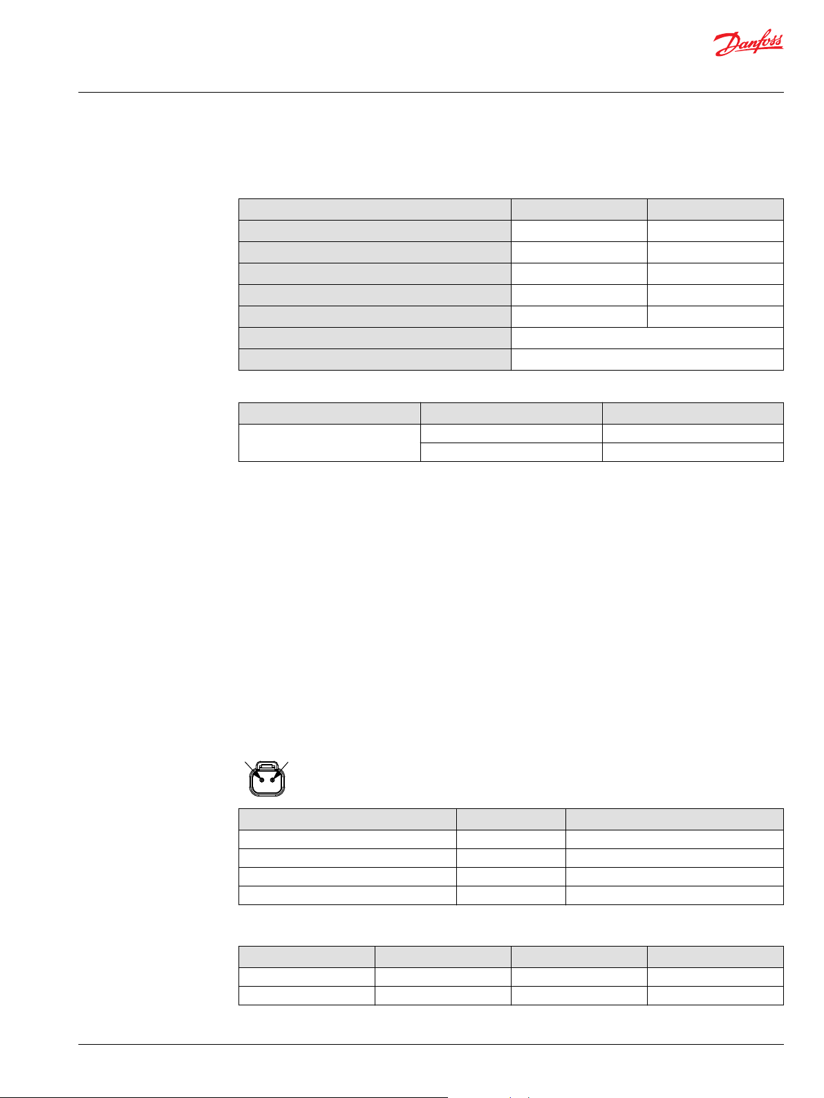
H1P 045/053 Technical Data
Feature Size 045 Size 053
Displacement
Flow at rated speed (continuous)
Torque at maximum displacement
(theoretical)
Mass moment of inertia of rotating
components
Mass (dry–no charge pump)
Oil volume
45.0 cm3 [2.75 in3] 53.8 cm3 [3.28 in3]
153 l/min [40 US gal/min] 183 l/min [48 US gal/min]
0.72 N•m/bar
[437.7 lbf•in/1000 psi]
0.00465 kg•m
[0.00343 slug•ft2]
41 kg [90 lb] 41 kg [90 lb]
1.3 l [0.34 US gal] 1.3 l [0.34 US gal]
2
0.86 N•m/bar
[522.0 lbf•in/1000 psi]
0.00458 kg•m
[0.00338 slug•ft2]
Shaft, flange and ports description
Input shaft per ISO 3019-1
(outer diameter)
Mounting flange per ISO 3019-1
Auxiliary mounting flange with metric
fasteners, with shaft outer diameter
Suction port per ISO 3019-1
Main configuration port
Case drain ports L2, L4 per ISO 3019-1
Other ports
Customer interface threads
Outer Ø22 mm – 4 (SAE B, 13 teeth)
•
Outer Ø25 mm – 4 (SAE B-B, 15 teeth)
•
Outer Ø32 mm – 4 (SAE B, 14 teeth)
•
Flange 101–2 (SAE B)
Flange 82-2 (SAE A, 9 teeth and 11 teeth)
•
Flange 101-2 (SAE B, 13 teeth and SAE B-B, 15 teeth)
•
15∕16–12 (SAE O-ring boss)
Ø19 mm, 450 bar Split flange boss per ISO 6162, M10x1.5
11∕16–12 (SAE O-ring boss)
SAE O-ring boss
Metric fasteners
2
6 | © Danfoss | December 2021 BC152886483105en-001501
Page 7
Technical Information
H1P 045/053 Axial Piston Single Pumps
Technical Specifications
H1P 045/053 Operating Parameters
Parameter Unit Size 045 Size 053
Input speed
System pressure
Charge pressure Minimum
Control pressure Minimum (at corner power for
Charge pump inlet
pressure
Case pressure Rated
Lip seal maximum pressure (external)
1)
Performance (displacement and pressure) may be limited due to limited control pressure.
2)
Full performance (displacement and pressure) possible at minimum charge and control pressure supply.
Min. for internal1) and external
charge supply
Min. for full performance,
internal charge supply
Rated
Maximum
Maximum working
Maximum
Max./Min. low loop
Maximum
EDC, MDC, FNR)
Minimum (at corner power for
NFPE, FDC, AC)
Maximum
Rated
Minimum (cold start)
Maximum
Maximum
2)
min-1 (rpm)
bar [psi]
bar [psi]
bar (absolute)
[in Hg vacuum]
bar [psi]
500 500
1175 1250
3400 3400
3500 3500
420 [6092 ] 380 [5511]
450 [6527] 400 [5802]
45/10 [653/145]
16 [232]
35 [508]
21.5 [312]
25 [363]
40 [580]
0.7 [9.0]
0.2 [24.0]
4.0 [58.0]
3.0 [44.0]
5.0 [73.0]
0.4 [5.8]
Filtration, cleanliness level and βx-ratio (recommended minimum)
Cleanliness per ISO 4406
Efficiency βx (charge pressure filtration)
Efficiency βx (suction and return line filtration)
Recommended inlet screen mesh size
©
Danfoss | December 2021 BC152886483105en-001501 | 7
22/18/13
β
= 75 (β10 ≥ 10)
15-20
β
= 75 (β10 ≥ 2)
35-45
100 – 125 µm
Page 8
Technical Information
H1P 045/053 Axial Piston Single Pumps
Technical Specifications
Fluid Specification
Viscosity
Intermittent
Minimum
Recommended range
Maximum
1)
Intermittent = Short term t < 1 min per incident and not exceeding 2 % of duty cycle based load-life.
Temperature
Minimum
Rated
Recommended range
Maximum Intermittent
1)
Cold start = Short term t > 3 min, p ≤ 50 bar [725 psi], n ≤ 1000 min-1 (rpm).
2)
At the hottest point, normally case drain port.
1)
1)
5 mm2/s [42 SUS]
7 mm2/s [49 SUS]
12 – 80 mm2/s [66 – 370 SUS]
1600 mm2/s [7500 SUS]
-40°C [-40°F]
104°C [220°F]
2)
60 – 85°C [140 – 185°F]
115°C [240°F]
8 | © Danfoss | December 2021 BC152886483105en-001501
Page 9
M
R
M
S
P301 214b
Technical Information
H1P 045/053 Axial Piston Single Pumps
Technical Specifications
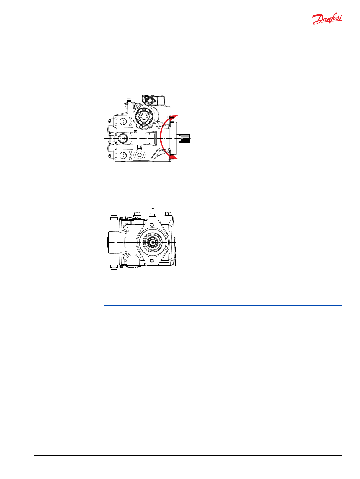
H1P 045/053 Mounting Flange Loads
The Rated and Shock load moments apply for top or side orientation of control.
Mounting flange load with control on top
Rated moment MR = 2020 N•m [17 880 lbf•in]
Shock load moment MS = 4110 N•m [ 36 380 lbf•in]
Mounting flange load with control on side
Rated moment MR = 1300 N•m [11 510 lbf•in]
Shock load moment MS = 2930 N•m [25 935 lbf•in]
For more information, see H1 Axial Piston Pumps, Basic Information, BC152886483968, the section
“Mounting flange loads”.
©
Danfoss | December 2021 BC152886483105en-001501 | 9
Page 10
P301 168
L
270° Re
Re
Me
180° Re
90° Re
0° Re
Re =
Me
L
Technical Information
H1P 045/053 Axial Piston Single Pumps
Technical Specifications
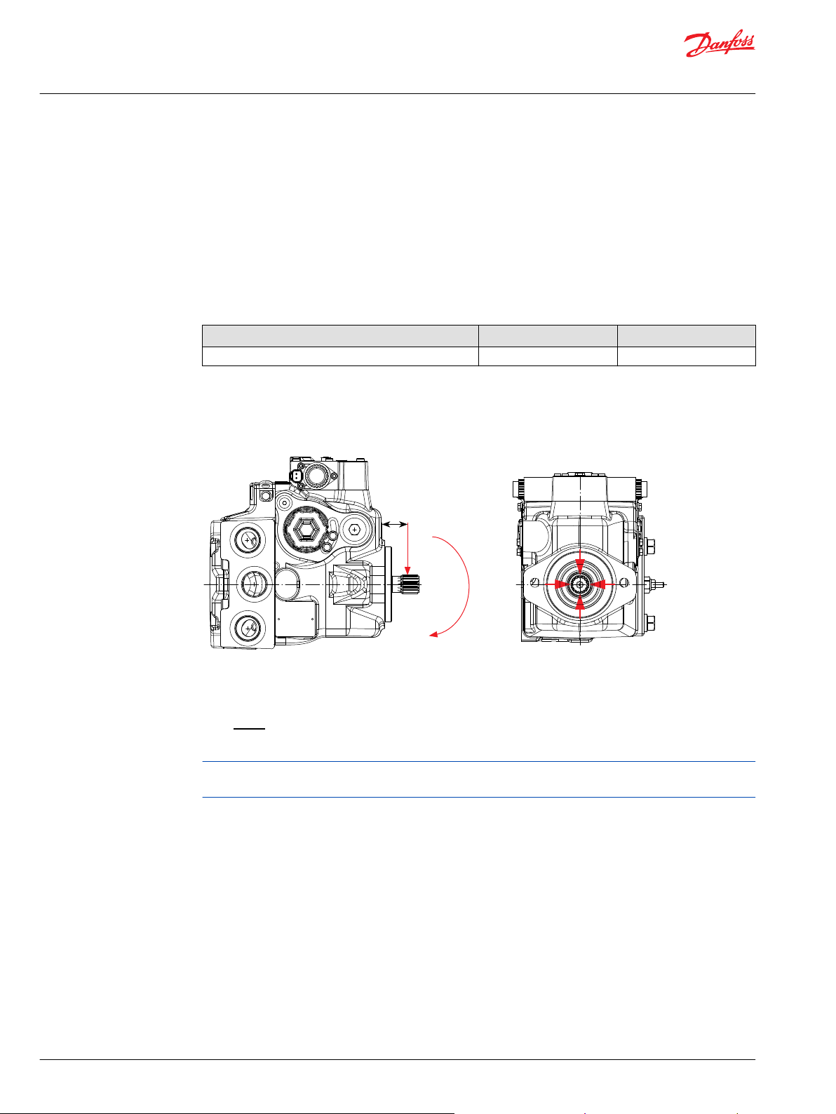
Bearing Life and External Radial Shaft Loads
All external shaft loads affect bearing life. The pumps are designed with bearings that can accept some
external radial loads. The external radial shaft load limits are a function of the load position and
orientation, and the operating conditions of the unit.
Danfoss recommends clamp-type couplings for applications with radial shaft loads. Contact your Danfoss
representative for an evaluation of unit bearing life if you have continuously applied external loads
exceeding 25 % of the maximum allowable radial load (Re) or the pump swash-plate is positioned on one
side of center all or most of the time.
Maximum external shaft load based on shaft deflection
External radial moment Unit Size 045/053
M
e
External radial shaft loads impact lifetime. For lifetime calculations please contact your Danfoss
representative. In applications with external shaft loads, minimize the impact by positioning the load at
0° or 180° as shown below.
Radial load position
N•m [lbf•in] TBD
The maximum allowable radial shaft load (Re) is based on the maximum external moment (Me) and the
distance (L) from the mounting flange to the load. It may be determined using the following formula:
Thrust loads should be avoided. Contact your Danfoss representative in the event thrust loads are
anticipated.
10 | © Danfoss | December 2021 BC152886483105en-001501
Page 11
00
1
3
6
9
12
14
10
20
30
40
50
0 500
1000
1500
2000
2500
3000
3500
4000
Speed min-1(rpm)
l/min
US gal/min
12 cm
3
[0.73 in
3
/rev]
P003 368E
0.5
1.0
1.0
2.0
3.0
4.0
5.0
1.5
2.5
3.5
2.0
3.0
Kw
HP
P003 369E
12 cm
3
[0.73 in
3
/rev]
000500
1000
1500
2000
2500
3000
3500
4000
Speed min-1(rpm)
Technical Information
H1P 045/053 Axial Piston Single Pumps
Technical Specifications
Charge pump
Charge Pump Selection
In most applications a general guideline is that the charge pump displacement should be at least 10% of
the total displacement of all components in the system. Unusual application conditions may require a
more detailed review of charge flow requirements. System features and conditions which may invalidate
the 10% guideline include (but are not limited to):
Continuous operation at low input speeds < 1500 min-1 (rpm)
•
High shock loading and/or long loop lines
•
High flushing flow requirements
•
Multiple low speed high torque motors
•
High input shaft speeds
•
Contact your Danfoss representative for application assistance if your application includes any of these
conditions.
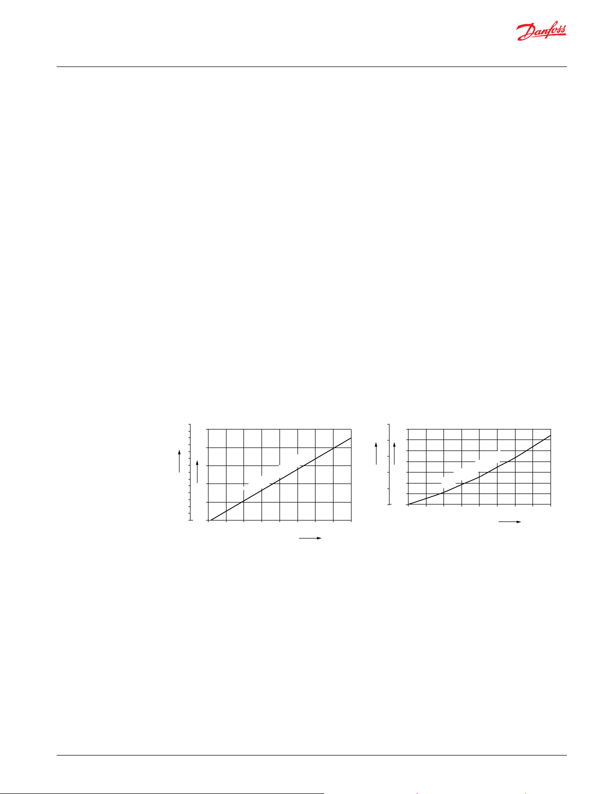
12 cm³ Charge Pump – Flow and Power Curves
Charge pump flow and power requirements curves shown below at the following conditions:
Charge pressure = 20 bar [290 psi]
Viscosity = 11 mm²/s [63 SUS]
Temperature = 80°C [176°F]
Charge pump flow
Charge pump power requirements
©
Danfoss | December 2021 BC152886483105en-001501 | 11
Page 12
G H J K M N S T V W X YZ D EF
H1P
A B
Technical Information
H1P 045/053 Axial Piston Single Pumps
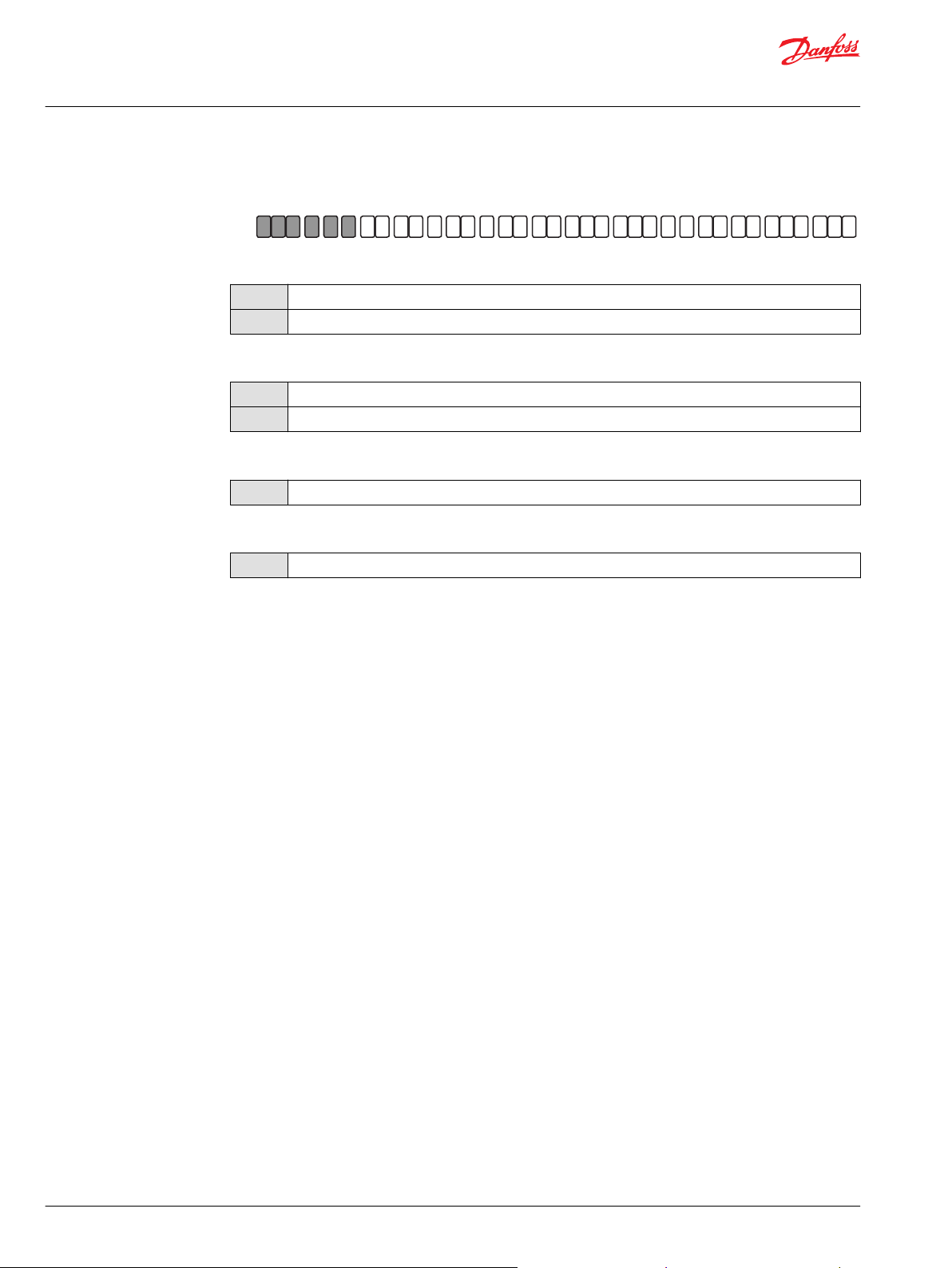
Master Model Code
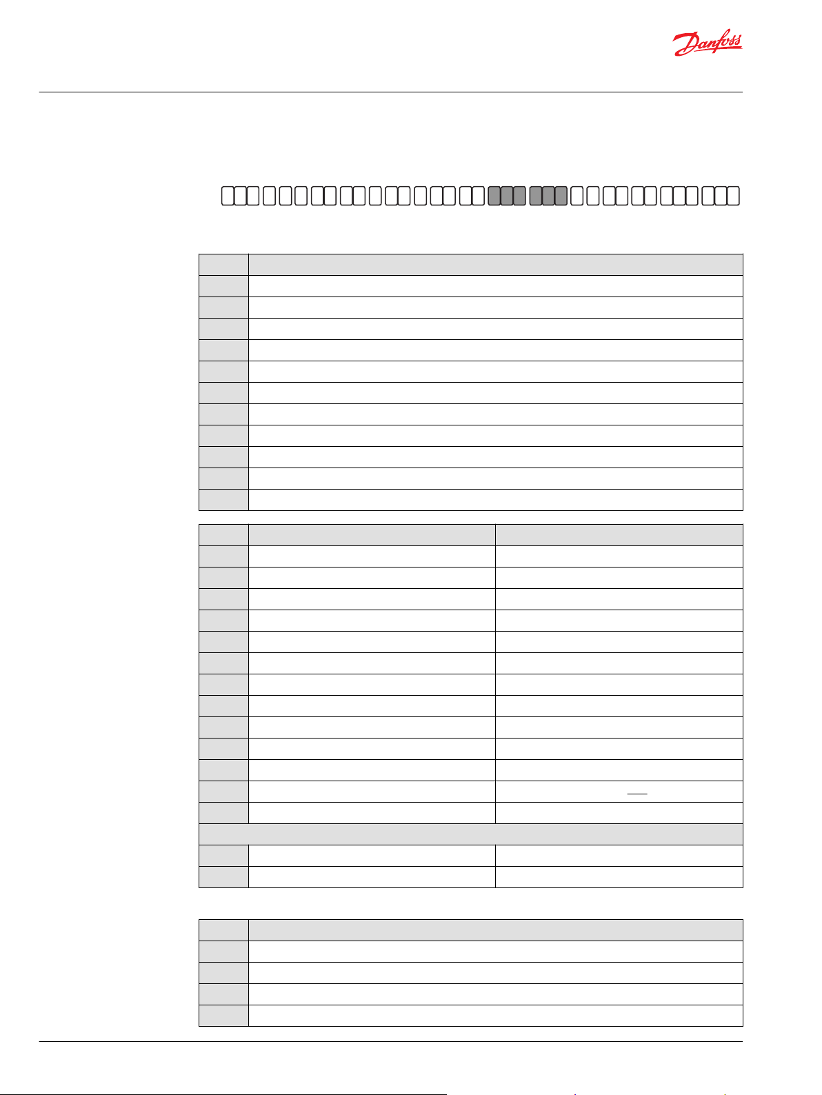
Displacement, A—Rotation, B—Product Version, Z—Port Configuration
Displacement
045
053
A – Direction of Rotation
L
R
B – Product version
A
Z – Port configuration
A
45.0 cm3 [2.75 in3]
53.8 cm3 [3.28 in3]
Left hand (counter clockwise)
Right hand (clockwise)
Revision code
Inch, Customer O-ring port sealing according to ISO 11926-1
12 | © Danfoss | December 2021 BC152886483105en-001501
Page 13
G H J K M N S T V W X YZ D EF
H1P
A B
Technical Information
H1P 045/053 Axial Piston Single Pumps
Master Model Code
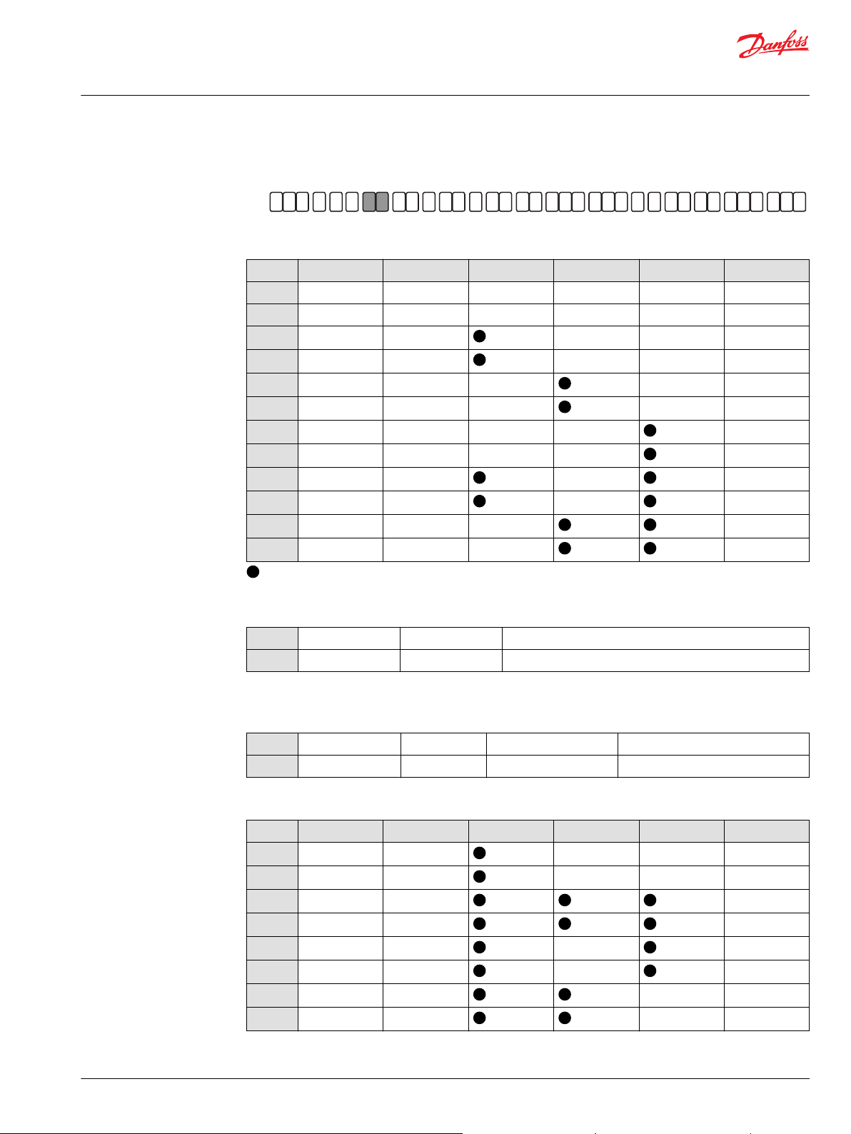
D—Controls
Electronic Displacement Controls
Code Control type Voltage MOR CCO with key C Angle sensor Connector
A2
A3
A4
A5
E7
E8
H2
H3
H6
H7
H8
H9
EDC 12 V — — — DEUTSCH
EDC 24 V — — — DEUTSCH
EDC 12 V — — DEUTSCH
EDC 24 V — — DEUTSCH
EDC 12 V — — DEUTSCH
EDC 24 V — — DEUTSCH
EDC 12 V — — DEUTSCH
EDC 24 V — — DEUTSCH
EDC 12 V — DEUTSCH
EDC 24 V — DEUTSCH
EDC 12 V — DEUTSCH
EDC 24 V — DEUTSCH
– To be used for the control; — Not to be used for the control
Fan Drive Controls
F1 FDC
F2 FDC
Align with options: F: Orifices, E: Displacement limiters, M, N: Overpressure protection, and W: Special hardware.
12 V DEUTSCH Connector
24 V DEUTSCH Connector
Forward-Neutral-Reverse (FNR) Controls
A9 FNR
B1 FNR
12 V with MOR DEUTSCH Connector
24 V with MOR DEUTSCH Connector
Non-Feedback Proportional Electric (NFPE) Controls
Code Control type Voltage MOR CCO with key C Angle sensor Connector
N1
N2
N3
N4
N5
N6
N7
N8
Align with options: E: Displacement limiters and W: Special hardware.
NFPE 12 V — — DEUTSCH
NFPE 24 V — — DEUTSCH
NFPE 12 V DEUTSCH
NFPE 24 V DEUTSCH
NFPE 12 V — DEUTSCH
NFPE 24 V — DEUTSCH
NFPE 12 V — DEUTSCH
NFPE 24 V — DEUTSCH
©
Danfoss | December 2021 BC152886483105en-001501 | 13
Page 14
Technical Information
H1P 045/053 Axial Piston Single Pumps
Master Model Code
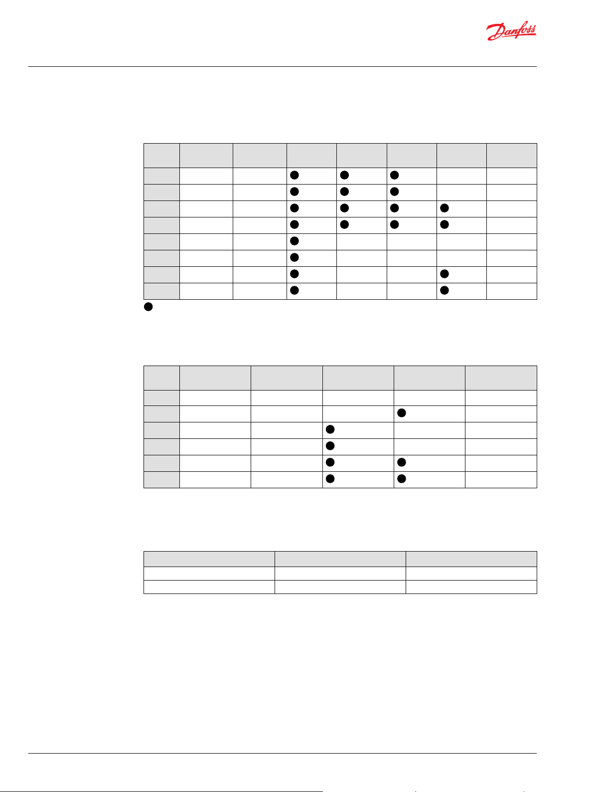
Automotive Controls
Automotive Control (AC)
Code AC type Voltage MOR Speed
P6
P7
P8
P9
P5
R3
R4
R5
Manual Displacement Control
AC–1 12 V — DEUTSCH
AC–1 24 V — DEUTSCH
AC–2 12 V DEUTSCH
AC–2 24 V DEUTSCH
AC–1 12 V — — — DEUTSCH
AC–1 24 V — — — DEUTSCH
AC–2 12 V — — DEUTSCH
AC–2 24 V — — DEUTSCH
– To be used for the control; — Not to be used for the control
sensor
Wire
harness
Angle
sensor
Connector
Manual Displacement Control (MDC)
Code Control type CCO Voltage CCO Neutral Start
M1
M2
M3
M4
M5
M6
Align with options F: Orifices and Y: Settings for adjustment (if applicable).
MDC — — — —
MDC — — DEUTSCH
MDC 12 V — DEUTSCH
MDC 24 V — DEUTSCH
MDC 12 V DEUTSCH
MDC 24 V DEUTSCH
Switch
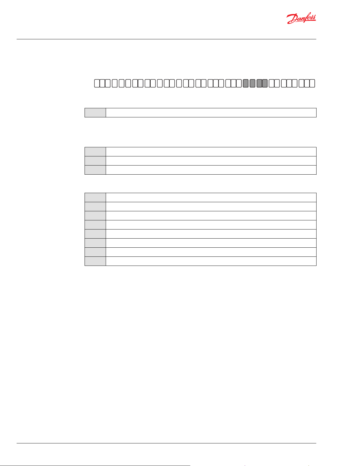
Hydraulic Displacement Control
Hydraulic Displacement Control (HDC)
Code Pressure range Ports
T1 4.2 - 16.2 bar Inch ports 9/16-18
T2 3.0 - 11.6 bar Inch ports 9/16-18
Connector
14 | © Danfoss | December 2021 BC152886483105en-001501
Page 15

G H J K M N S T V W X YZ D EF
H1P
A B
Technical Information
H1P 045/053 Axial Piston Single Pumps
Master Model Code
F—Orifices, E—Displacement Limiters
F – Orifices Options
Orifices options related to control type
Code Tank (A+B) P orifice A/B orifices EDC, FNR MDC NFPE, AC FDC
C3
C1
C2
C4
C6
C7
D1
D2
D3
D4
D5
D6
D8
– – 0.8 mm –
– – 1.3 mm
– – 1.8 mm –
1.0 mm – – – –
1.3 mm – – – – –
0.8 mm 1.0 mm – – – –
0.8 mm 1.3 mm – – – –
1.0 mm 1.3 mm – – – –
1.0 mm 1.3 mm 1.3 mm – – –
0.6 mm 0.6 mm 0.8 mm – – –
1.3 mm 1.3 mm – – – –
– – 2.3 mm – – –
No orifice – –
E – Displacement Limiter Options
N
B
C
D
*
Align with option Y: Settings for adjustment (if applicable).
None
Adjustable externally
No limiters, with nested springs, required for NFPE, AC, FDC
Adjustable externally with nested springs, required for NFPE, AC, FDC
*
*
©
Danfoss | December 2021 BC152886483105en-001501 | 15
Page 16
G H J K M N S T V W X YZ D EF
H1P
A B
Technical Information
H1P 045/053 Axial Piston Single Pumps
Master Model Code
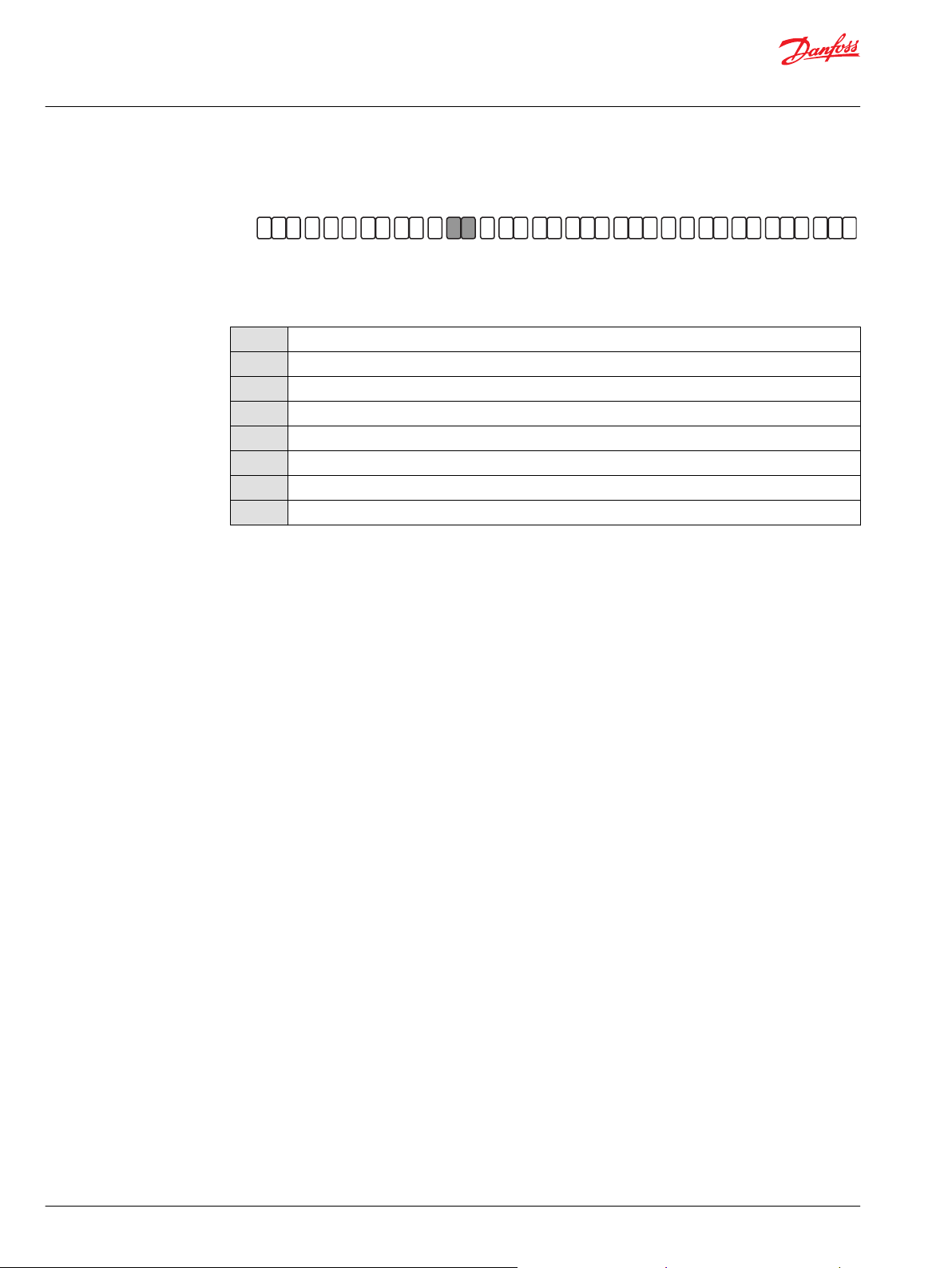
G—Endcap
G – End-cap Options
Twin port, ISO 6162 split flange ports; Align with T: Filtration
D6 Suction filtration, Code 62
E6 Suction filtration, ORB
F1 Suction filtration, ORB, HPRV only
F3 Suction filtration, Code 62, HPRV only
D8 Remote filtration, Code 62
E5 Remote filtration, ORB
E9 Remote filtration, ORB, HPRV only
F2 Remote filtration, Code 62, HPRV only
16 | © Danfoss | December 2021 BC152886483105en-001501
Page 17
G H J K M N S T V W X YZ D EF
H1P
A B
Technical Information
H1P 045/053 Axial Piston Single Pumps
Master Model Code
H—Mounting Flange, J—Input Shaft, K—Aux Pad
H – Mounting options
Mounting to be aligned with option W: Special hardware
F
J
J – Input Shaft options
ISO 3019-1 flange 101–2 (SAE B)
ISO 3019-1 flange 101–2 (SAE B), 2-bolt, with speed sensor
G1
G4
G5
ISO 3019-1, outer Ø32 mm - 4 (14 teeth splined shaft 12/24 pitch)
ISO 3019-1, outer Ø22 mm - 4 (13 teeth splined shaft 16/32 pitch)
ISO 3019-1, outer Ø25 mm - 4 (15 teeth splined shaft 16/32 pitch)
K – Auxiliary Mounting Pad options (ISO 3019-1)
NN
H1
H2
H3
H5
None
Flange 82–2 (SAE A, 11 teeth, 16/32 coupling); shipping cover
Flange 82–2 (SAE A, 9 teeth, 16/32 coupling); shipping cover
Flange 101–2 (SAE B, 13 teeth, 16/32 coupling); shipping cover
Flange 101–2 (SAE B-B, 15 teeth, 16/32 coupling); shipping cover
©
Danfoss | December 2021 BC152886483105en-001501 | 17
Page 18
G H J K M N S T V W X YZ D EF
H1P
A B
Technical Information
H1P 045/053 Axial Piston Single Pumps
Master Model Code
M, N—Overpressure Protection Settings
M and N – Overpressure protection options
J Pressure limiter setting
J18
J20
J23
J25
J28
J30
J33
J35
J38
J40
J42
180 bar [2610 psi]
200 bar [2900 psi]
230 bar [3336 psi]
250 bar [3630 psi]
280 bar [4061 psi]
300 bar [4350 psi]
330 bar [4786 psi]
350 bar [5076 psi]
380 bar [5511 psi]
400 bar [5800 psi] (H1P 045 only)
420 bar [6090 psi] (H1P 045 only)
L Pressure limiter setting HPRV with bypass setting
L15
L18
L20
L23
L25
L28
L30
L33
L35
L38
L40
L41
L42
Overpressure protection type and setting for FDC
F01
F02
1)
Pressure limiter and HPRV with bypass, over-pressure protection type must be the same for both sides “A” and “B”.
K Pressure setting
K18
K20
K23
K25
150 bar [2900 psi] 230 bar [3336 psi]
180 bar [2610 psi] 230 bar [3336 psi]
200 bar [2900 psi] 250 bar [3630 psi]
230 bar [3336 psi] 280 bar [4061 psi]
250 bar [3630 psi] 300 bar [4350 psi]
280 bar [4061 psi] 330 bar [4786 psi]
300 bar [4350 psi] 350 bar [5076 psi]
330 bar [4786 psi] 380 bar [5510 psi]
350 bar [5080 psi] 400 bar [5800 psi]
380 bar [5510 psi] 420 bar [6090 psi]
400 bar [5800 psi] 450 bar [6526 psi] (H1P 045 only)
410 bar [5946 psi] 450 bar [6526 psi] (H1P 045 only)
420 bar [6090 psi] 450 bar [6526 psi] (H1P 045 only)
150 bar [2175 psi] 250 bar [3630 psi]
150 bar [2175 psi] 300 bar [4350 psi] (H1P 045 only)
1)
180 bar [2610 psi]
200 bar [2900 psi]
230 bar [3336 psi]
250 bar [3630 psi]
1)
18 | © Danfoss | December 2021 BC152886483105en-001501
Page 19
Technical Information
H1P 045/053 Axial Piston Single Pumps
Master Model Code
K Pressure setting
K28
K30
K33
K35
K38
K40
K41
K42
1)
Pressure limiter and HPRV with bypass, over-pressure protection type must be the same for both sides “A” and “B”.
280 bar [4061 psi]
300 bar [4350 psi]
330 bar [4786 psi]
350 bar [5076 psi]
380 bar [5510 psi]
400 bar [5800 psi] (available for H1P 045 only)
410 bar [5946 psi] (available for H1P 045 only)
420 bar [6090 psi] (available for H1P 045 only)
1)
Please contact Danfoss Power Solutions for pressures not shown or for applied pressure above max.
working pressure.
©
Danfoss | December 2021 BC152886483105en-001501 | 19
Page 20
G H J K M N S T V W X YZ D EF
H1P
A B
Technical Information
H1P 045/053 Axial Piston Single Pumps
Master Model Code
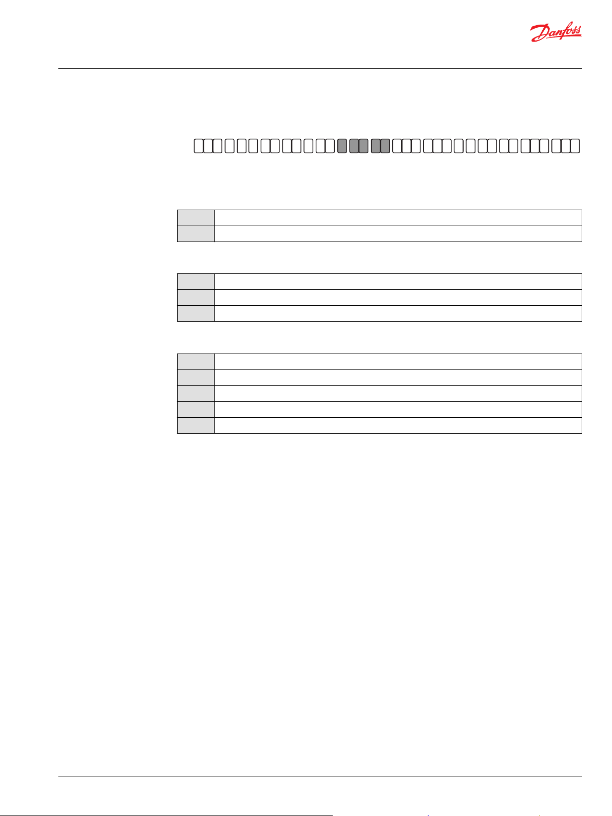
S—Charge Pump, T—Filtration, V—Charge Pressure Relief
S – Charge pump options
B
12 cm³/rev [0.73 in³/rev]
T – Filtration options
Filtration to be aligned with G: End cap selection
L
P
E
Suction filtration
Remote full charge flow filtration
External full charge flow filtration (Align with options N, S)
V – Charge pressure relief valve (CPRV) setting
*
*
*
*
18 bar [261 psi]
20 bar [290 psi]
22 bar [319 psi]
24 bar [348 psi]
26 bar [377 psi]
28 bar [406 psi]
30 bar [435 psi]
32 bar [464 psi]
18
20
22
24
26
28
30
32
*
Not to be used for NFPE, AC and FDC controls.
20 | © Danfoss | December 2021 BC152886483105en-001501
Page 21
G H J K M N S T V W X YZ D EF
H1P
A B
Technical Information
H1P 045/053 Axial Piston Single Pumps
Master Model Code
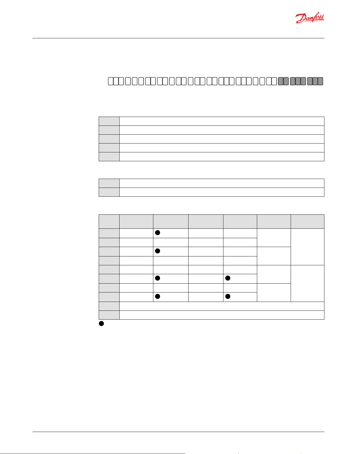
W—Special Hardware, X—Paint, Y—Special Features
W – Special Hardware features
Hardware features to be aligned with options D, E
P1
P2
P4
PN
H1
X – Paint and Name-tag
NFPE/FDC valve plate
NFPE/FDC/AC valve plate and speed ring on the cylinder block
EDC/FNR/MDC valve plate and speed ring on the cylinder block
EDC/FNR/MDC valve plate
MDC/EDC/FNR valve plate with MDC handle
NNN
C08
Black paint and Danfoss name-tag
Paint none and Danfoss name-tag
Y – Special settings (SIL-2 non-certifiable, without customer files)
Code CAN J1939 ECO fuel saving
D3E
D3F
D4E
D4F
D5F
D5J
D6F
D6J
M00
NNN
– To be used for the control; — Not to be used for the control
in/out E –
in/out – F –
in/out E –
in/out – F –
in/out – F –
in/out J
in/out – F –
in/out J
MDC handle standard position
None
mode
Functional
option
Cruise control Control AC type
N1
(12 VDC)
N2
(24 VDC)
P8
(12 VDC)
P9
(24 VDC)
AC–1
AC–2
(with swash
plate angle
sensor)
©
Danfoss | December 2021 BC152886483105en-001501 | 21
Page 22
P003 191
Feedback from
Swash plate
PTF00B
M14
C1 C2
F00A
P003 478E
"0"
-b -a
ba
100 %
100 %
Displacement
Current mA
Technical Information
H1P 045/053 Axial Piston Single Pumps
Control Options
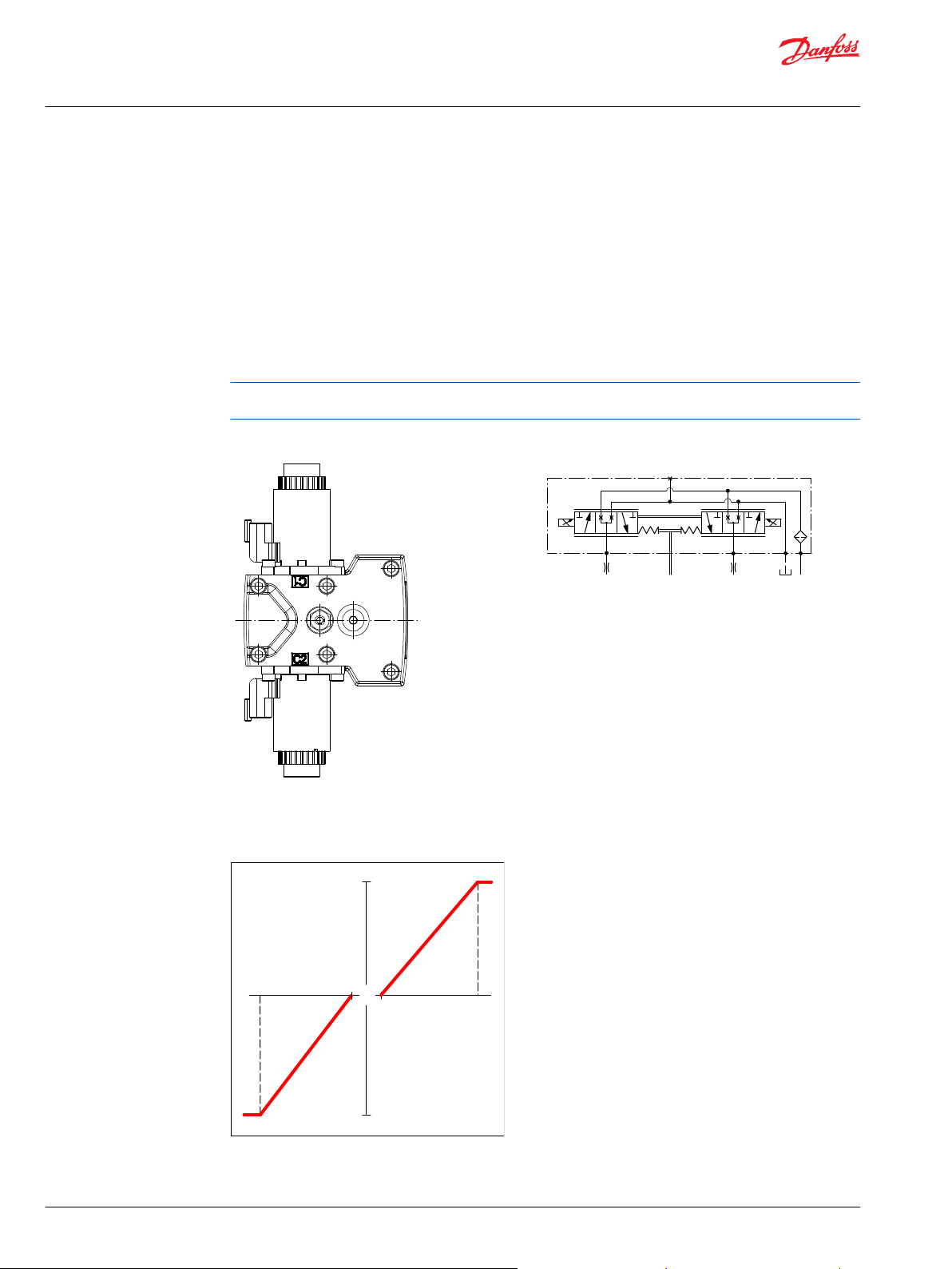
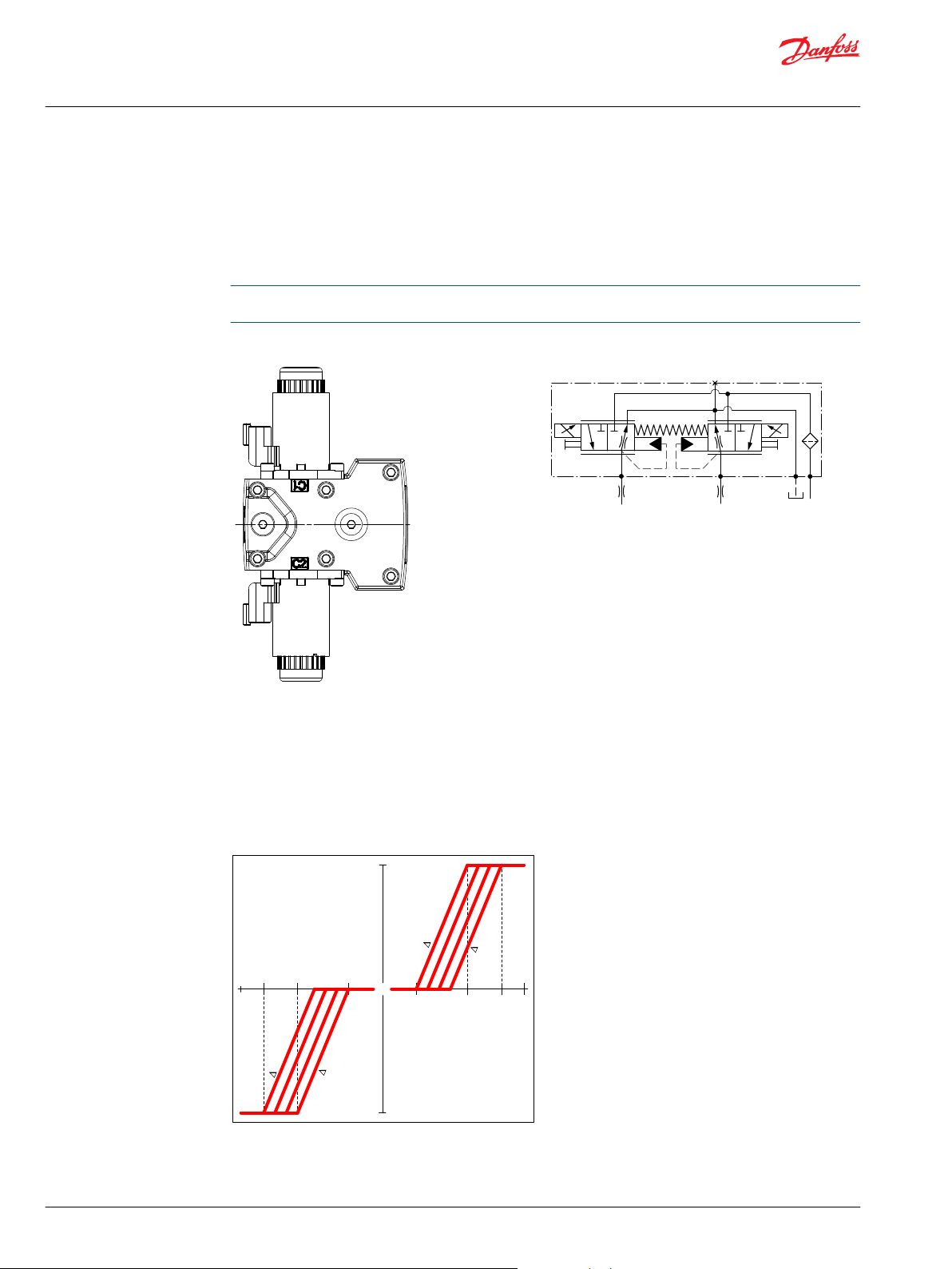
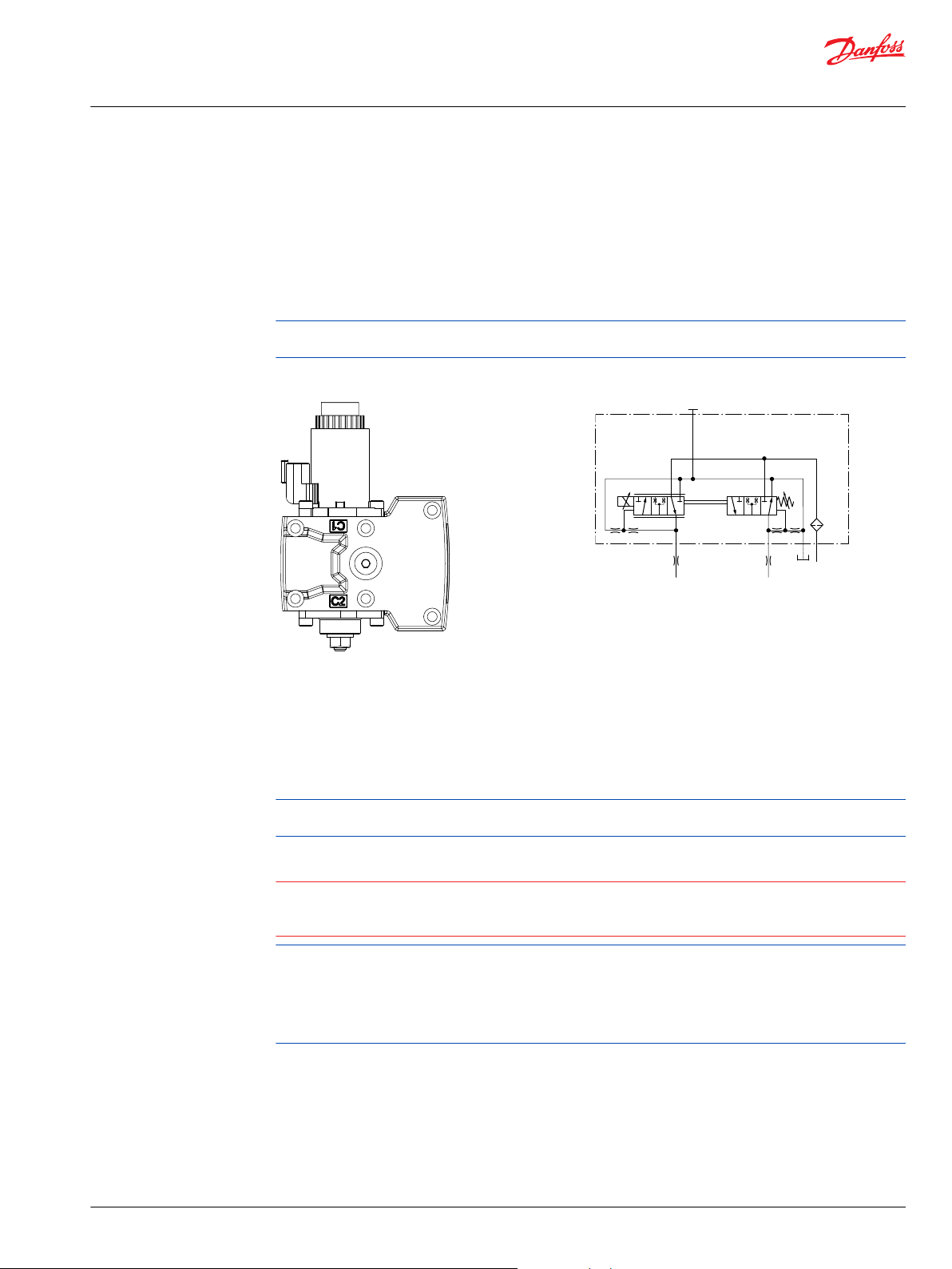
Electrical Displacement Control (EDC)
An EDC is a displacement (flow) control. Pump swash plate position is proportional to the input
command and therefore vehicle or load speed (excluding influence of efficiency), is dependent only on
the prime mover speed or motor displacement.
The Electrical Displacement Control (EDC) consists of a pair of proportional solenoids on each side of a
three-position, four-way porting spool. The proportional solenoid applies a force input to the spool,
which ports hydraulic pressure to either side of a double acting servo piston. Differential pressure across
the servo piston rotates the swash plate, changing the pump‘s displacement from full displacement in
one direction to full displacement in the opposite direction.
A serviceable 170 μm screen is located in the supply line immediately before the control porting spool.
Under some circumstances, such as contamination, the control spool could stick and cause the pump to
stay at some displacement.
Electrical Displacement Control
Control signal requirements, EDC 045/053
Pump displacement vs. control current
EDC schematic, feedback from swash plate
22 | © Danfoss | December 2021 BC152886483105en-001501
Page 23
2
1
Technical Information
H1P 045/053 Axial Piston Single Pumps
Control Options
EDC control current
Voltage 12 V
Minimum current to stroke pump a
Pin connections any order
*
Factory test current, for vehicle movement or application actuation expect higher or lower value.
Control Solenoid Data
Description 12 V 24 V
Maximum current 1800 mA 920 mA
Nominal coil resistance @ 20 °C [68 °F] 3.66 Ω 14.20 Ω
Inductance 33 mH 140 mH
PWM signal frequency Range 70 – 200 Hz
IP Rating IEC 60 529 IP 67
Connector color Black
*
PWM signal required for optimum control performance.
DC
*
640 mA 330 mA
b 1640 mA 820 mA
@ 80 °C [176 °F] 4.52 Ω 17.52 Ω
Recommended
*
100 Hz
DIN 40 050, part 9 IP 69K with mating connector
24 V
DC
Single Pump Output Flow Direction
Shaft rotation Clock-Wise (CW) Counter-Clock-Wise (CCW)
Coil energized
*
C1 C2 C1 C2
Port A out in in out
Port B in out out in
Servo port pressurized M4 M5 M4 M5
*
For coil location see installation drawings.
Connector
Connector DEUTSCH, 2-pin
Description Quantity Order data
Mating connector 1 DEUTSCH DT06-2S
Wedge lock 1 DEUTSCH W2S
Socket contact (16–18 AWG) 2 DEUTSCH 0462-201-16141
Danfoss mating connector kit 1 K29657
©
Danfoss | December 2021 BC152886483105en-001501 | 23
Page 24
Technical Information
H1P 045/053 Axial Piston Single Pumps
Control Options
Control response
H1P controls are available with optional control passage orifices to assist in matching the rate of swashplate response to the application requirements (e.g. in the event of electrical failure).
The time required for the pump output flow to change from zero to full flow (acceleration) or full flow to
zero (deceleration) is a net function of spool porting, orifices, and charge pressure.
A swash-plate response times table is available for each frame size. Testing should be conducted to verify
the proper orifice selection for the desired response. Typical response times at the following conditions:
Δ p = 250 bar [3626 psi]
Charge pressure = 20 bar [290 psi]
Viscosity and temperature = 30 mm²/s [141 SUS] and 50 °C [122 °F]
Speed = 1800 min-1 (rpm)
Response Time, EDC 045/053
Stroking direction 0.8 mm [0.03 in] orifice 1.3 mm [0.05 in] orifice No orifice
Neutral to full flow 1.7 s 0.9 s 0.5 s
Full flow to neutral 1.1 s 0.6 s 0.3 s
24 | © Danfoss | December 2021 BC152886483105en-001501
Page 25
"0"
Lever rotation
"A"
Displacement
100 %
a
-a
100 %
"B"
-b
-d
b
c
d
-c
P301 752
Technical Information
H1P 045/053 Axial Piston Single Pumps
Control Options
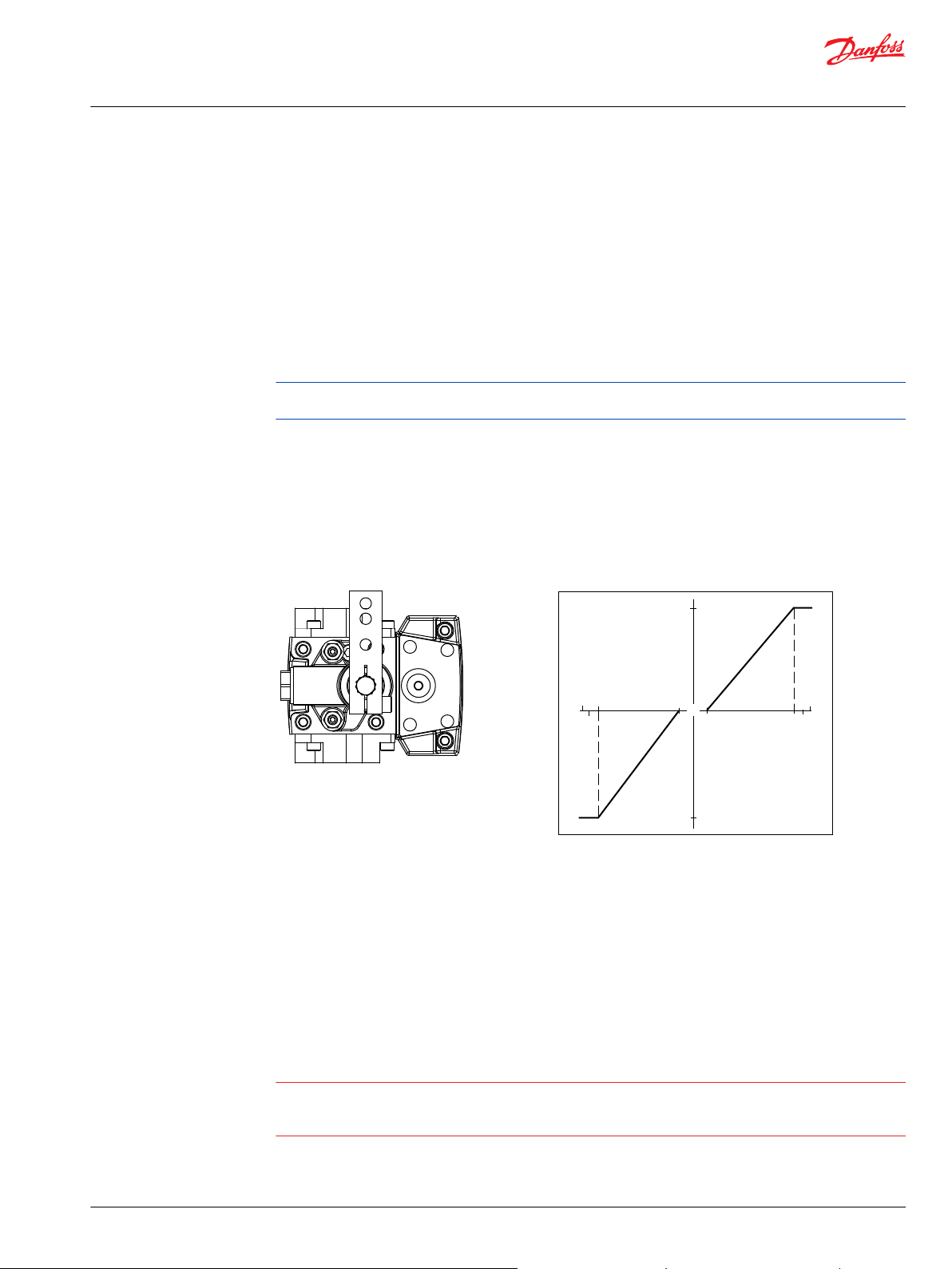
Manual Displacement Control (MDC)
A Manual proportional Displacement Control (MDC) consists of a handle on top of a rotary input shaft.
The shaft provides an eccentric connection to a feedback link. This link is connected on its one end with a
porting spool. On its other end the link is connected the pumps swashplate.
This design provides a travel feedback without spring. When turning the shaft the spool moves thus
providing hydraulic pressure to either side of a double acting servo piston of the pump.
Differential pressure across the servo piston rotates the swash plate, changing the pump’s displacement.
Simultaneously the swashplate movement is fed back to the control spool providing proportionality
between shaft rotation on the control and swash-plate rotation. The MDC changes the pump
displacement between no flow and full flow into opposite directions.
Under some circumstances, such as contamination, the control spool could stick and cause the pump to
stay at some displacement.
For the MDC with CCO option the brake port (X7) provides charge pressure when the coil is energized to
activate static function such as a brake release. The X7 port must not be used for any continuous oil
consumption.
The MDC is sealed by means of a static O-ring between the actuation system and the control block. Its
shaft is sealed by means of a special O-ring which is applied for low friction. The special O-ring is
protected from dust, water and aggressive liquids or gases by means of a special lip seal.
Manual Displacement Control Pump displacement vs. control lever rotation
Deadband on B side: a = 3° ±1°
Maximum pump stroke: b = 30° +2/-1°
Required customer end stop: c = 36° ±3°
Internal end stop: d = 40°
MDC operation
The MDC provides a mechanical dead-band required to overcome the tolerances in the mechanical
actuation. The MDC contains an internal end stop to prevent turning the handle into any inappropriate
position.
The MDC provides a permanent restoring moment appropriate for turning the MDC input shaft back to
neutral position only. This is required to take the backlash out of the mechanical connections between
the Bowden cable and the control.
High case pressure may cause excessive wear and the NSS to indicate that the control is not in neutral
©
Danfoss | December 2021 BC152886483105en-001501 | 25
position. In addition, if the case pressure exceeds 5 bar there is a risk of an insufficient restoring moment.
The MDC is designed for a maximum case pressure of 5 bar and a rated case pressure of 3 bar.
Page 26

C
CCW
CW
C
Technical Information
H1P 045/053 Axial Piston Single Pumps
Control Options
Customers must install some support to limit the setting range of their Bowden cable to avoid an
•
overload of the MDC.
Customers can apply their own handle design but they must care about a robust clamping
•
connection between their handle and the control shaft and avoid overload of the shaft.
Customers can connect two MDC’s on a tandem unit in such a way that the actuation force will be
•
transferred from the pilot control to the second control. The kinematic of the linkages must ensure
that either control shaft is protected from torque overload.
Caution
Using the internal spring force on the input shaft is not an appropriate way to return the customer
connection linkage to neutral, or to force a Bowden cable or a joystick back to neutral position. It is not
applicable for any limitation of the Bowden cable stroke, except the applied torque to the shaft will never
exceed 20 N•m.
MDC shaft rotation
Pump shaft rotation
MDC shaft rotation CW CCW CW CCW
Port A in (low) out (high) out (high) in (low)
Port B out (high) in (low) in (low) out (high)
Servo port high pressure M5 M4 M5 M4
*
As seen from shaft side.
*
Clockwise (CW) Counter-clockwise (CCW)
MDC Torque
Description Value
Torque required to move handle to maximum displacement 1.4 N•m [12.39 lbf•in ]
Torque required to hold handle at given displacement 0.6 N•m [5.31 lbf•in]
Maximum allowable input torque 20 N•m [177 lbf•in]
Caution
Volumetric efficiencies of the system will have impacts on the start and end input commands.
26 | © Danfoss | December 2021 BC152886483105en-001501
Page 27

2
1
Technical Information
H1P 045/053 Axial Piston Single Pumps
Control Options
Control response
H1P controls are available with optional control passage orifices to assist in matching the rate of swashplate response to the application requirements (e.g. in the event of electrical failure).
The time required for the pump output flow to change from zero to full flow (acceleration) or full flow to
zero (deceleration) is a net function of spool porting, orifices, and charge pressure.
A swash-plate response times table is available for each frame size. Testing should be conducted to verify
the proper orifice selection for the desired response. Typical response times at the following conditions:
Δ p = 250 bar [3626 psi]
Charge pressure = 20 bar [290 psi]
Viscosity and temperature = 30 mm²/s [141 SUS] and 50 °C [122 °F]
Speed = 1800 min-1 (rpm)
Response time, MDC 045/053
Code Orifice description (mm) Stroking direction
Tank (A+B) P A/B Neutral to full flow Full flow to neutral
C3
C6
C7
D1
D2
D3
D4
1 – – 0.9 s 0.8 s
1.3 – – 0.6 s 0.6 s
0.8 1 – 1.7 s 1.2 s
0.8 1.3 – 1.5 s 1.1 s
1 1.3 – 1.1 s 0.8 s
1 1.3 1.3 1.3 s 1.0 s
No orifice 0.3 s 0.4 s
For further data please contact your Danfoss representative.
Connector
Connector DEUTSCH, 2-pin
Description Quantity Order data
Mating connector 1 DEUTSCH DT06-2S
Wedge lock 1 DEUTSCH W2S
Socket contact (16–18 AWG) 2 DEUTSCH 0462-201-16141
Danfoss mating connector kit 1 K29657
©
Danfoss | December 2021 BC152886483105en-001501 | 27
Page 28

P005 702
M14
M5
M4
M3
Technical Information
H1P 045/053 Axial Piston Single Pumps
Control Options
Neutral start switch (NSS)
The Neutral Start Switch (NSS) contains an electrical switch that provides a signal of whether the control
is in neutral. The signal in neutral is Normally Closed (NC).
Neutral start switch schematic
Neutral start switch data
Max. continuous current with switching
Max. continuous current without switching
Max. voltage
Electrical protection class
8.4 A
20 A
36 V
DC
IP67 / IP69K with mating connector
Case Gauge Port M14
The drain port should be used when the control is mounted on the unit’s bottom side to flush residual
contamination out of the control.
Lever
MDC-controls are available with an integrated lever.
28 | © Danfoss | December 2021 BC152886483105en-001501
Page 29

P400520
P400519
X1
F00B
F00A
Feedback from
Swashplate
T P
X2M14
Technical Information
H1P 045/053 Axial Piston Single Pumps
Control Options
Hydraulic Displacement Control (HDC)
HDC principle
An HDC is a Hydraulic Displacement Control. Pump swashplate position is proportional to the input
command and therefore vehicle speed or load speed (excluding influence of efficiency), is dependent
only on the prime mover speed or motor displacement.
The HDC control uses a hydraulic input signal to operate a porting spool, which ports hydraulic pressure
to either side of a double acting servo piston. The hydraulic signal applies a force input to the spool
which ports hydraulic pressure to either side of a double acting servo piston. Differential pressure across
the servo piston rotates the swashplate, changing the pump’s displacement from full displacement in
one direction to full displacement in the opposite direction. Under some circumstances, such as
contamination, the porting spool could stick and cause the pump to stay at some displacement.
A serviceable 175 μm screen is located in the supply line immediately before the control porting spool.
HDC control
HDC schematic
HDC operation
HDC’s are hydraulically driven control which ports hydraulic pressure to either side of a porting spool,
which pressurizes one end of the servo piston, while draining the other end to case. Pressure differential
across the servo piston moves the swashplate.
A swashplate feedback link, opposing control linkage, and a linear spring provide swashplate position
force feedback to the hydraulic pressure. As hydraulic pressures in the operating loop change with load,
the control assembly and servo/swashplate system work constantly to maintain the commanded position
of the swashplate.
©
Danfoss | December 2021 BC152886483105en-001501 | 29
Page 30

"0"
Signal pressure
Displacement
100 %
a b
-b -a
100 %
P102 031E
Technical Information
H1P 045/053 Axial Piston Single Pumps
Control Options
The HDC incorporates a positive neutral dead band as a result of the control spool porting, preloads from
the servo piston assembly, and the linear control spring. Once the neutral threshold point is reached, the
swashplate is positioned directly proportional to the control pressure.
When the control input is either lost or removed, or if there is a loss of charge pressure, the spring loaded
servo piston will automatically return the pump to the neutral position.
Pump displacement vs signal pressure
Hydraulic signal pressure range
Type Unit Start of control End of control
Option bar 3.0 11.6
Standard 4.2 16.2
Pump output flow direction vs. control pressure
Shaft rotation HDC Clockwise (CW) seen from shaft Counter Clockwise (CCW) seen from shaft
Port energized X1 X2 X1 X2
Port A Out (high) In (low) In (low) Out (high)
Port B In (low) Out (high) Out (high) In (low)
Servo port high
pressure
M4 M5 M4 M5
For appropriate performance of HDC characteristic, keep the drain pressure of pilot valve to be equal or
slightly higher than pump case pressure.
Control response
H1P controls are available with optional control passage orifices to assist in matching the rate of swashplate response to the application requirements (e.g. in the event of electrical failure).
The time required for the pump output flow to change from zero to full flow (acceleration) or full flow to
zero (deceleration) is a net function of spool porting, orifices, and charge pressure.
A swash-plate response times table is available for each frame size. Testing should be conducted to verify
the proper orifice selection for the desired response. Typical response times at the following conditions:
Δ p = 250 bar [3626 psi]
Charge pressure = 20 bar [290 psi]
Viscosity and temperature = 30 mm²/s [141 SUS] and 50 °C [122 °F]
Speed = 1800 min-1 (rpm)
30 | © Danfoss | December 2021 BC152886483105en-001501
Page 31

Technical Information
H1P 045/053 Axial Piston Single Pumps
Control Options
Response Time, HDC 045/053
Stroking direction 0.8 mm [0.03 in] orifice 1.3 mm [0.05 in] orifice No orifice
Neutral to full flow 1.6s 0.7s 0.4s
Full flow to neutral 0.9s 0.4s 0.2s
©
Danfoss | December 2021 BC152886483105en-001501 | 31
Page 32

P003 193
P003 189
C2C1
F00A
M14
T PF00B
100 %
“0“
100 %
Voltage V
DC
Displacement
Technical Information
H1P 045/053 Axial Piston Single Pumps
Control Options
Forward-Neutral-Reverse Control (FNR)
The 3-position FNR control options A9 (12 V) and B1 (24 V) uses an electric input signal to switch the
pump to a full stroke position. A serviceable 125 μm screen is located in the supply line immediately
before the control porting spool.
Under some circumstances, such as contamination, the control spool can stick and cause the pump to
stay at some displacement.
Forward-Neutral-Reverse electric control (FNR)
FNR hydraulic schematic
Pump displacement vs. electrical signal
FNR control current
Voltage 12 V
DC
Minimum current to stroke pump 750 mA 380 mA
Pin connections any order
24 V
DC
Single Pump Output Flow Direction
Shaft rotation Clock-Wise (CW) Counter-Clock-Wise (CCW)
Coil energized
*
C1 C2 C1 C2
Port A in out out in
Port B out in in out
Servo port pressurized M5 M4 M5 M4
*
For coil location see installation drawings.
32 | © Danfoss | December 2021 BC152886483105en-001501
Page 33
2
1
Technical Information
H1P 045/053 Axial Piston Single Pumps
Control Options
FNR Solenoid Data
Solenoid data
Voltage 12 V
Minimum supply voltage
Maximum supply voltage (continuous)
Bi-directional diode cut off voltage
Maximum current
Nominal coil resistance @ 20°C
PWM Range
PWM Frequency (preferred)
*
PWM signal required for optimum control performance.
Electrical Protection Standard Class
IP Rating IEC 60 529 IP 67
DC
9.5 V
DC
14.6 V
DC
28 V
DC
1050 mA 500 mA
8.4 Ω 34.5 Ω
70 – 200 Hz
*
DIN 40 050, part 9 IP 69K with mating connector
100 Hz
24 V
19 V
29 V
53 V
DC
DC
DC
DC
Control response
H1P controls are available with optional control passage orifices to assist in matching the rate of swashplate response to the application requirements (e.g. in the event of electrical failure).
The time required for the pump output flow to change from zero to full flow (acceleration) or full flow to
zero (deceleration) is a net function of spool porting, orifices, and charge pressure.
A swash-plate response times table is available for each frame size. Testing should be conducted to verify
the proper orifice selection for the desired response. Typical response times at the following conditions:
Δ p = 250 bar [3626 psi]
Charge pressure = 20 bar [290 psi]
Viscosity and temperature = 30 mm²/s [141 SUS] and 50 °C [122 °F]
Speed = 1800 min-1 (rpm)
Connector
Connector DEUTSCH, 2-pin
Description Quantity Order data
Mating connector 1 DEUTSCH DT06-2S
Wedge lock 1 DEUTSCH W2S
Socket contact (16–18 AWG) 2 DEUTSCH 0462-201-16141
Danfoss mating connector kit 1 K29657
Response Time, FNR 045/053
Stroking direction 0.8 [0.03] orifice 1.3 [0.05] orifice No orifice
Neutral to full flow 1.8 s 0.9 s 0.5 s
Full flow to neutral 1.6 s 0.8 s 0.4 s
©
Danfoss | December 2021 BC152886483105en-001501 | 33
Page 34
P003 192
P003 188
C2C1
F00A
M14
T PF00B
"0"
Signal current (mA)
a b c
abc
Displacement
100 %
100 %
p = 300 bar
p = 300 bar
p = 0 bar
p = 0 bar
Technical Information
H1P 045/053 Axial Piston Single Pumps
Control Options
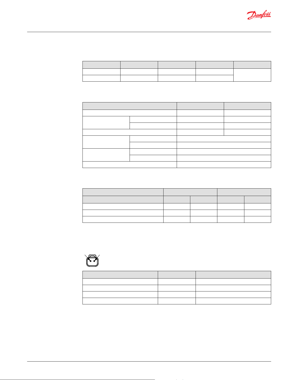
Non feedback proportional electric control (NFPE)
The Non Feedback Proportional Electric (NFPE) control is an electrical automotive control in which an
electrical input signal activates one of two proportional solenoids that port charge pressure to either side
of the pump servo cylinder. The NFPE control has no mechanical feedback mechanism.
A serviceable 170 μm screen is located in the supply line immediately before the control porting spool.
Under some circumstances, such as contamination, the control spool could stick and cause the pump to
stay at some displacement.
NFPE control
NFPE schematic
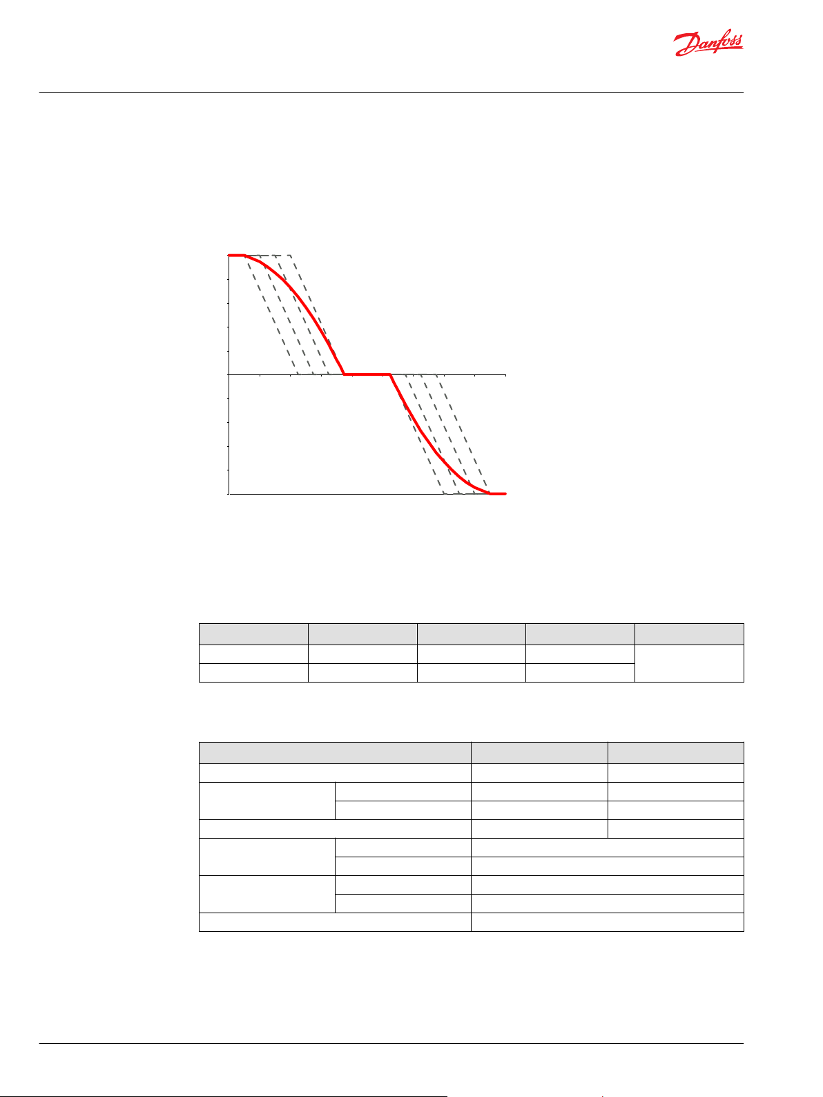
Control Signal Requirements, NFPE 045/053
The pump displacement is proportional to the solenoid signal current, but it also depends upon pump
input speed and system pressure. This characteristic also provides a power limiting function by reducing
the pump swash-plate angle as system pressure increases.
A typical response characteristic is shown in the accompanying graph below:
Pump displacement vs. input signal
34 | © Danfoss | December 2021 BC152886483105en-001501
Page 35
2
1
Technical Information
H1P 045/053 Axial Piston Single Pumps
Control Options
Control current requirements
*
Voltage
12 V
DC
24 V
DC
*
Factory test current, for vehicle movement or application actuation expect higher or lower value.
Control Solenoid Data
Description 12 V 24 V
Maximum current 1800 mA 920 mA
Nominal coil resistance @ 20 °C [68 °F] 3.66 Ω 14.20 Ω
Inductance 33 mH 140 mH
PWM signal frequency Range 70 – 200 Hz
IP Rating IEC 60 529 IP 67
Connector color Black
*
PWM signal required for optimum control performance.
a b c Pin config.
310 mA 1050 mA 1540 mA
309 mA 551 mA 770 mA
any order
@ 80 °C [176 °F] 4.52 Ω 17.52 Ω
Recommended
*
100 Hz
DIN 40 050, part 9 IP 69K with mating connector
Single Pump Output Flow Direction
Shaft rotation Clock-Wise (CW) Counter-Clock-Wise (CCW)
Coil energized
*
C1 C2 C1 C2
Port A in out out in
Port B out in in out
Servo port pressurized M5 M4 M5 M4
*
For coil location see installation drawings.
Connector
Connector DEUTSCH, 2-pin
Description Quantity Order data
Mating connector 1 DEUTSCH DT06-2S
Wedge lock 1 DEUTSCH W2S
Socket contact (16–18 AWG) 2 DEUTSCH 0462-201-16141
Danfoss mating connector kit 1 K29657
©
Danfoss | December 2021 BC152886483105en-001501 | 35
Page 36

Technical Information
H1P 045/053 Axial Piston Single Pumps
Control Options
Control response
H1P controls are available with optional control passage orifices to assist in matching the rate of swashplate response to the application requirements (e.g. in the event of electrical failure).
The time required for the pump output flow to change from zero to full flow (acceleration) or full flow to
zero (deceleration) is a net function of spool porting, orifices, and charge pressure.
A swash-plate response times table is available for each frame size. Testing should be conducted to verify
the proper orifice selection for the desired response. Typical response times at the following conditions:
Δ p = 250 bar [3626 psi]
Charge pressure = 20 bar [290 psi]
Viscosity and temperature = 30 mm²/s [141 SUS] and 50 °C [122 °F]
Speed = 1800 min-1 (rpm)
Response Time, NFPE 045/053
Stroking direction 0.8 mm [0.03 in] orifice 1.3 mm [0.05 in] orifice 2.3 mm [0.09 in] orifice
Neutral to full flow 1.8 s 0.8 s 0.3 s
Full flow to neutral 1.2 s 0.5 s 0.2 s
36 | © Danfoss | December 2021 BC152886483105en-001501
Page 37
P003 544
CAN PPC PSC PPU
CC2
CC1
WARRANTY VOID IF REMOVED
CC3
Technical Information
H1P 045/053 Axial Piston Single Pumps
Control Options
Automotive Control (AC)
The H1 Aautomotive Control (AC) is an electric NFPE Control with an integrated micro-controller,
installed on the pump. The integrated micro-controller enhanced control performance with a flexible,
configurable control scheme for an entire single path propel transmission. It can be used in combination
with fixed and variable displacement hydraulic-motors. With the pre-installed application software and
easily changeable control parameters, it is possible to tailor the vehicle’s driving behavior to the
individual requirements of the customer.
The H1 Automotive Control is divided into 2 systems:
AC-1
•
AC-2
•
AC-2 is an extension of AC-1 that features an integrated pump swash plate angle sensor and software
enabled functions such as Swash Plate Control.
Mode types
The application software provides 3 different hydrostatic propel methods, defined as mode types, which
can be used individually.
Automotive Load dependent (torque controlled) driving behavior. Setpoint for the drive curve is
•
the engine rpm.
Non-Automotive Load independent (speed controlled) driving mode. Setpoint for the drive curve is
•
a Joystick or drive pedal signal, independent of the engine rpm. The best performance will achieved
with an AC-2 Swash Plate Angle Sensor.
Creep-Automotive Load dependent (torque controlled) driving behavior (like Automotive).
•
Setpoint for the drive curve is the engine rpm. The setpoint can be reduced by the creep
potentiometer if a high engine rpm in combination with low vehicle speed is needed.
Basic functions
Four selectable system modes, selectable via switch.
•
Individual settings for forward and reverse driving direction (4 x 2 curves).
•
Independent pump and hydraulic-motor profiling and ramping for each mode.
•
Electric drive pedal connection
•
Electronic inching function without separate control valve
•
Electric creep mode potentiometer
•
©
Danfoss | December 2021 BC152886483105en-001501 | 37
Page 38

Technical Information
H1P 045/053 Axial Piston Single Pumps
Control Options
Configurable System Mode & Direction change
•
Load independent pump displacement control with integrated Swash Plate Angle Sensor (AC-2)
•
Hydraulic-motor displacement control including brake pressure defeat function
•
Performance functions
ECO fuel saving mode with automatic reduction of the engine speed during transport (Cruise control)
•
Vehicle constant speed drive control
•
Vehicle speed limitation
•
Dynamic brake light, automatic park brake, reverse buzzer and status LED outputs
•
Vehicle speed controlled output function.
•
Temperature compensation for predictable performance
•
Advanced CAN J1939 interface for the information exchange with the vehicle control system
•
Protection and safety functions
Safety controlled vehicle start protection with engine speed check, battery check and FNR must be in
•
neutral, etc..
Operator presence detection
•
Hydraulic system overheat and low-temperature protection
•
Hydraulic motor over speed protection
•
Park brake test mode for roller applications to fulfill SAE J1472 / EN500-4.
•
SIL2 compliant
•
Engine control and protection
CAN J1939 engine interface
•
Engine speed control via drive pedal with safety controlled monitoring function
•
Engine antistall protection
•
Engine over speed protection during inching
•
Engine speed dependent Retarder control
•
Engine cold start protection
•
Installation features
Factory calibration for hysteresis compensation.
•
Starting current adjustment in the factory
•
Pre-installed application software and parameter files
•
For more information, see Automotive Control for H1 Single Pumps Technical Information,
BC152986482596.
38 | © Danfoss | December 2021 BC152886483105en-001501
Page 39
P301 441
PT
F00B
M14
C1 C2
F00A
P301 442
W
Technical Information
H1P 045/053 Axial Piston Single Pumps
Control Options
Fan Drive Control (FDC)
The Fan Drive Control (FDC) is a non-feedback control in which an electrical input signal activates the
proportional solenoid that ports charge pressure to either side of the pump servo cylinder. The single
proportional solenoid is used to control pump displacement in the forward or reverse direction.
The control spool is spring biased to produce maximum forward pump displacement in the absence of
an electrical input signal. Based on the spring bias spool default forward flow for a CW rotation pump is
out of port B while default forward flow for a CCW rotation pump is out of port A.
Under some circumstances, such as contamination, the control spool could stick and cause the pump to
stay at some displacement.
FDC control
FDC schematic
The pump should be configured with 0.8 mm control orifices to provide slowest response and maximize
system stability. Additionally, pressure limiter (PL) valves are used to limit maximum fan trim speed in
both (forward and reverse) directions.
H1 pumps with FDC will be delivered from factory with nominal pressure limiter setting of 150 bar [2175
psi]. The PL must be re-adjusted to ensure that the fan reaches the desired fan speed to satisfy the
cooling needs of the system. HPRV setting must be always at least 30 bar [435 psi] higher than PL setting.
For more information necessary to properly size and configure a hydraulic fan drive system, see Hydraulic
Fan Drive Design Guidelines AB152886482265.
©
Danfoss | December 2021 BC152886483105en-001501 | 39
Warning
Use in other systems could result in unintended movement of the machine or it’s elements. Loss of the
input signal to this control will cause the pump to produce maximum flow.
The FDC is for Fan Drive systems only!
Due to the fail-safe functionality of the FDC control the pump will stroke to max. displacement in case the
input signal to the pump control and the Diesel engine will be switched off at the same time. In this
situation a low loop event can occur which may damage the pump. Therefore, it’s strictly recommended
to keep the input signal to the pump control alive while switching off the engine.
For further information please contact your Danfoss representative.
Page 40
100%
100%
Displacement
0
Signal current (mA(DC
Avg
))
Max. current
N
a
b
∆
p = 0 bar
∆
p = 0 bar
∆
p = 300 bar
Reverse
Forward
Technical Information
H1P 045/053 Axial Piston Single Pumps
Control Options
Control Signal Requirements, FDC 045/053
The pump displacement is proportional to the solenoid signal current, but it also depends upon pump
input speed and system pressure. This characteristic also provides a power limiting function by reducing
the pump swash plate angle as system pressure increases. A typical response characteristic is shown in
the accompanying graph below:
a – Forward threshold
b – Reverse threshold
N – Neutral override current
Control current requirements
*
Voltage
12 V
DC
24 V
DC
*
Factory test current, for fan movement expect higher or lower value.
a N b Pin config.
780 mA 1100 mA 1300 mA
400 mA 550 mA 680 mA
any order
Control Solenoid Data
Description 12 V 24 V
Maximum current 1800 mA 920 mA
Nominal coil resistance @ 20 °C [68 °F] 3.66 Ω 14.20 Ω
@ 80 °C [176 °F] 4.52 Ω 17.52 Ω
Inductance 33 mH 140 mH
PWM signal frequency Range 70 – 200 Hz
IP Rating IEC 60 529 IP 67
DIN 40 050, part 9 IP 69K with mating connector
Connector color Black
*
PWM signal required for optimum control performance.
Recommended
*
100 Hz
40 | © Danfoss | December 2021 BC152886483105en-001501
Page 41

W
2
1
Technical Information
H1P 045/053 Axial Piston Single Pumps
Control Options
Single Pump Output Flow Direction
Pump output flow direction vs. control signal
Shaft rotation ClockWise CounterClockWise
Control Logic 12 V 0-780 mA 1100 mA 1300-1800 mA 0-780 mA 1100 mA 1300-1800 mA
Port A in no flow out out no flow in
Port B out no flow in in no flow out
Servo port pressurized M5 n/a M4 M5 n/a M4
Warning
Loss of input signal to the control will cause the pump to produce maximum flow.
Connector
Connector DEUTSCH, 2-pin
24 V 0-400 mA 550 mA 680-920 mA 0-400 mA 550 mA 680-920 mA
Description Quantity Order data
Mating connector 1 DEUTSCH DT06-2S
Wedge lock 1 DEUTSCH W2S
Socket contact (16–18 AWG) 2 DEUTSCH 0462-201-16141
Danfoss mating connector kit 1 K29657
Control response
H1P controls are available with optional control passage orifices to assist in matching the rate of swashplate response to the application requirements (e.g. in the event of electrical failure).
The time required for the pump output flow to change from zero to full flow (acceleration) or full flow to
zero (deceleration) is a net function of spool porting, orifices, and charge pressure.
A swash-plate response times table is available for each frame size. Testing should be conducted to verify
the proper orifice selection for the desired response. Typical response times at the following conditions:
Δ p = 250 bar [3626 psi]
Charge pressure = 20 bar [290 psi]
Viscosity and temperature = 30 mm²/s [141 SUS] and 50 °C [122 °F]
Speed = 1800 min-1 (rpm)
Response Time, FDC 045/053
Stroking direction 0.8 mm [0.03 in] orifice
Full flow to neutral 1.9 s
Full forward flow to full reverse flow 2.8 s
©
Danfoss | December 2021 BC152886483105en-001501 | 41
Page 42

P003 204
PTF00B
M14
C2
C1
F00A
W
Technical Information
H1P 045/053 Axial Piston Single Pumps
Control Options
Manual Override (MOR)
All controls are available with a manual override functionality, either as a standard or as an option for
temporary actuation of the control to aid in diagnostics.
Control with manual override
MOR schematic (EDC control shown)
Feedback from swash plate.
The MOR plunger has a 4 mm diameter and must be manually depressed to be engaged. Depressing the
plunger mechanically moves the control spool which allows the pump to go on stroke. The MOR should
be engaged anticipating a full stroke response from the pump.
An o-ring seal is used to seal the MOR plunger where initial actuation of the function will require a force
of 45 N to engage the plunger. Additional actuation typically require less force to engage the MOR
plunger.
Proportional control of the pump using the MOR should not be expected.
Warning
Unintended MOR operation will cause the pump to go into stroke; example: vehicle lifted off the ground.
The vehicle or device must always be in a safe condition when using the MOR function.
Refer to control flow table for the relationship of solenoid to direction of flow.
42 | © Danfoss | December 2021 BC152886483105en-001501
Page 43
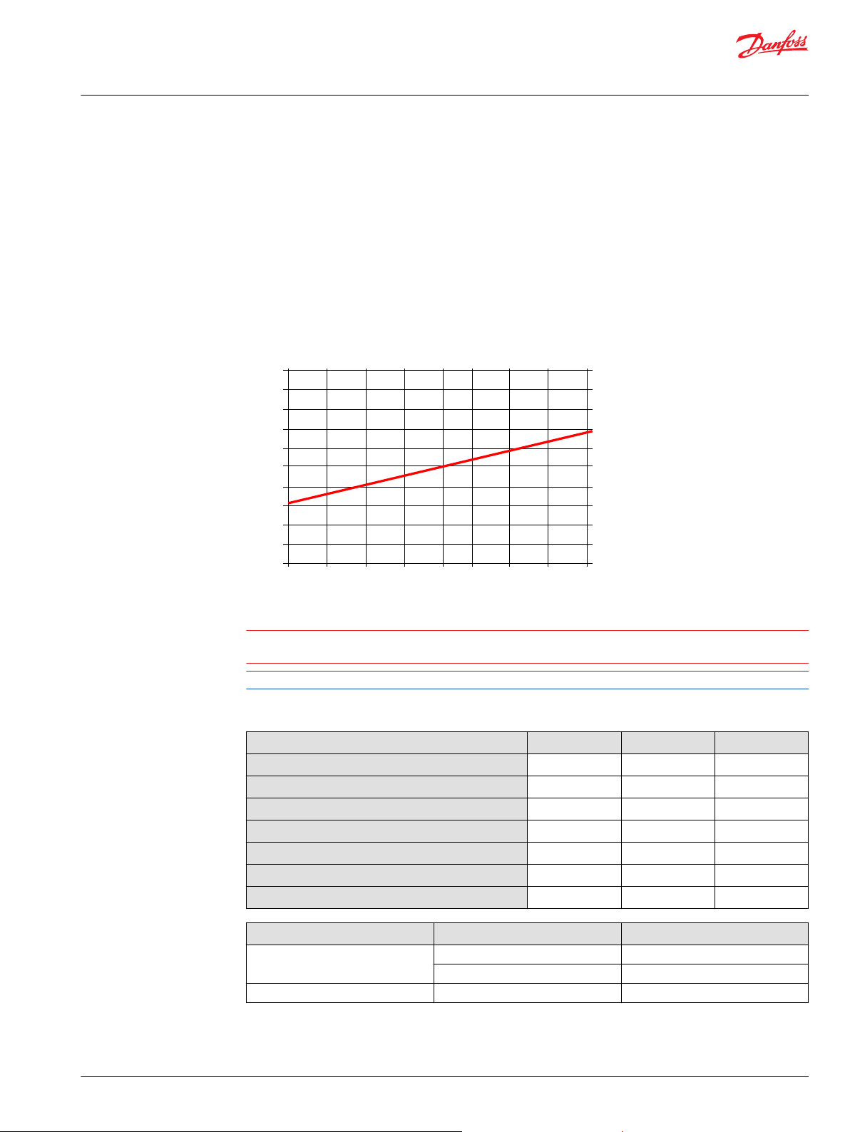
-18° -13° -8°
100%
90%
80%
70%
60%
50%
40%
30%
20%
10%
0%
Swashplate angle
Sensor output, % of supply voltage
-3° 0° 2° 7° 12° 17°
W
Technical Information
H1P 045/053 Axial Piston Single Pumps
Control Options
Swashplate angle sensor for EDC controls
The angle sensor detects the swash plate position with an accuracy dependent upon the calibration
effort done for the application and direction of rotation from the neutral position. At minimum the sensor
can be used for forward, neutral and reverse (FNR) detection.
The sensor works on the hall-effect technology. The implemented technology is based on a
measurement of the magnetic field direction in parallel to the chip surface. This field direction is
converted to a voltage signal at the output.
Enhanced calibration of the non-linear behavior leads to more exact calculation of the pump swashplate
angle. The 4-pin DEUTSCH connector is part of the sensor housing. The swashplate angle sensor is
available for all EDC controls for 12 V and 24 V.
Swashplate angle vs. output of supply voltage
Warning
Strong magnetic fields in the proximity of the sensor can influence the sensor signal and must be
avoided.
Contact your Danfoss representative in case the angle sensor will be used for safety functions.
Swash plate angle sensor parameters (EDC)
Parameter Minimum Typical Maximum
Supply voltage range
Supply protection
Pump neutral output (% of supply voltage)
Working range (swash plate angle)
Required supply current
Output current signal
Working temperature
4.5 V
DC
– – 18 V
– 50% –
–18° – 18°
– – 30 mA
– 9 mA 11 mA
–40 °C 80 °C 115 °C
Electrical Protection Standard Class
IP Rating IEC 60 529 IP 67
DIN 40 050, part 9 IP 69K with mating connector
EMC Immunity ISO 11452-2 100 V/m
©
Danfoss | December 2021 BC152886483105en-001501 | 43
5 V
DC
5.5 V
DC
DC
Page 44

2
3
4
1
ECU
Supply
Signal
GND
GND
OUT
VCC
100 nF
20 kΩ
100 nF
Technical Information
H1P 045/053 Axial Piston Single Pumps
Control Options
Calibration of the sensor output within the software is mandatory. Vehicle neutral thresholds in the
software (±0.5°) are vehicle dependent and must consider different conditions, example: system
temperature, system pressure and/or shaft speed.
For safety function: If the sensor fails (invalid signal <10% or >90% of supply voltage), it must be sure
that the ECU will go into a diagnostic mode and shift into limited mode in order for the driver to take the
full control or the mechanical breaks should be activated. Strong magnetic fields in the proximity of the
sensor can influence the sensor signal and must be avoided.
H1P Swash Plate Angle Sensor Connector
Connector DEUTSCH, 4-pin
1 Ground (GND)
2 Not connected
3 Output signal 1 (SIG 1)
4 Supply (V+)
Description Quantity Order number
Mating connector 1 DEUTSCH DTM06-4S-E004
Wedge lock 1 DEUTSCH WM-4S
Socket contact 4 DEUTSCH 0462-201-2031
Blind socket 1 DEUTSCH 0413-204-2005
Danfoss mating connector kit 1 11212713
Interface with ECU (EDC)
Interface with ECU diagram
44 | © Danfoss | December 2021 BC152886483105en-001501
Page 45

P301 750
-25° -20° -15° -10° -5° 0° 5° 10° 15° 20° 25°
5
4.5
4
3.5
3
2.5
2
1.5
1
0.5
0
Swashplate angle
Output voltage (V)
1
2
(cm )
3
V =
tan
α • V
tan 18°
(l/min)
Q =
V • n • h
vol
1000
Technical Information
H1P 045/053 Axial Piston Single Pumps
Control Options
Swash Plate Angle Sensor for NFPE and AC2 Controls
The angle sensor detects the swash plate angle position and direction of rotation from the zero position.
The swash angle sensor works on the AMR sensing technology. Under the saturated magnetic field, the
resistance of the element varies with the magnetic field direction.
The output signal give a linear output voltage for the various magnet positions in the sensing range.
Swash Plate Angle Characteristic
The volumetric losses depend on pump max. displacement, actual displacement, speed, delta pressure,
viscosity and temperature.
Swashplate angle vs. output voltage (calibrated at 50 °C)
©
Danfoss | December 2021 BC152886483105en-001501 | 45
1. Signal 1 (nominal)
2. Signal 2 (redundant)
The displacement can be calculated by: The corresponding flow is:
Page 46

2
3
4
1
ECU
V+
Sig1
Sig2
Gnd
E3
340R 340R
Out 2
Out 1
VCC
VCC
Gnd
Gnd
340R340R
0.1uF
5.6 nF
5.6 nF
E2
E1
Technical Information
H1P 045/053 Axial Piston Single Pumps
Control Options
Swash Plate Angle Sensor Parameters (NFPE/AC)
Parameter Minimum Typical Maximum
Supply voltage range
Supply protection
Supply current
Output current (Signal 1, 2)
Short circuit output current to supply or GND
Sensitivity
Working range (swash plate angle)
Correlation between signals 1 and 2
1)
Up to duration of 2.5 seconds at 25°C
2)
Signal 1 (nominal) is lower than signal 2 (redundant)
H1P Swash Plate Angle Sensor Connector (NFPE)
4.75 V 5 V 5.25 V
– – 28 V
– 22 mA 25 mA
– 0.1 mA –
1)
– – 7.5 mA
70.0 mV/deg 78.0 mV/deg 85.8 mV/deg
–18° 0° 18°
2)
475 mV 500 mV 525 mV
1 Ground (GND)
2 Output Signal 2 (SIG 2) – Secondary (redundant)
3 Output signal 1 (SIG 1)
4 Supply (V+)
Description Quantity Order number
Mating connector 1 DEUTSCH DTM06-4S-E004
Wedge lock 1 DEUTSCH WM-4S
Socket contact 4 DEUTSCH 0462-201-2031
Blind socket 1 DEUTSCH 0413-204-2005
Danfoss mating connector kit 1 11212713
Interface with ECU (NFPE)
46 | © Danfoss | December 2021 BC152886483105en-001501
Minimum recommended load resistance is 100 kΩ.
Page 47

P005 703
M14
X7
C
Technical Information
H1P 045/053 Axial Piston Single Pumps
Control Options
Control Cut Off Valve (CCO)
The H1 pump offers an optional control cut off valve integrated into the control. All EDC, NFPE and MDC
controls are available with a CCO valve. This valve will block charge pressure to the control, allowing the
servo springs to de-stroke both pumps regardless of the pump´s primary control input.
There is also a hydraulic logic port, X7, which can be used to control other machine functions, such as
spring applied pressure release brakes. The pressure at X7 is controlled by the control cut off solenoid.
The X7 port would remain plugged if not needed.
In the normal (de-energized) state of the solenoid charge flow is prevented from reaching the controls. At
the same time the control passages and the X7 logic port are connected and drained to the pump case.
The pump will remain in neutral, or return to neutral, independent of the control input signal. Return to
neutral time will be dependent on oil viscosity, pump speed, swashplate angle, and system pressure.
When the solenoid is energized, charge flow and pressure is allowed to reach the pump control. The X7
logic port will also be connected to charge pressure and flow.
The solenoid control is intended to be independent of the primary pump control making the control cut
off an override control feature. It is however recommended that the control logic of the CCO valve be
maintained such that the primary pump control signal is also disabled whenever the CCO valve is deenergized. Other control logic conditions may also be considered.
The CCO valve is available with 12 V or 24 V solenoid.
The response time of the unit depends on the control type and the used control orifices.
CCO schematic (MDC shown)
Brake gauge port with MDC
Caution
It is not recommended to use brake port for any external flow consumption to avoid malfunction of CCO
function.
©
Danfoss | December 2021 BC152886483105en-001501 | 47
Page 48

2
1
2 1
Technical Information
H1P 045/053 Axial Piston Single Pumps
Control Options
CCO Connector (MDC)
Connector DEUTSCH, 2-pin
Description Quantity Order data
Mating connector 1 DEUTSCH DT06-2S
Wedge lock 1 DEUTSCH W2S
Socket contact (16–18 AWG) 2 DEUTSCH 0462-201-16141
Danfoss mating connector kit 1 K29657
H1P CCO Connector (EDC, NFPE)
Connector CCO DEUTSCH, 2-pin with key C
Description Quantity Order number
Mating connector 1 DEUTSCH DT06-2S-C015
Wedge lock 1 DEUTSCH W2SC-P012
Socket contact 4 DEUTSCH 0462-201-16141
Danfoss mating connector kit 1 11212714
CCO solenoid data
Nominal supply voltage 12 V 24 V
Supply voltage Maximum
Minimum
Bi-directional diode cut off voltage
Nominal coil resistance at 20 °C
Supply current Maximum
Minimum
PWM frequency Range
Preferred
Electrical protection class
14.6 V 29 V
9.5 V 19 V
28 V 53 V
10.7 Ω 41.7 Ω
850 mA 430 mA
580 mA 300 mA
50 – 200 Hz
100 Hz
IP67 / IP69K with mating connector
CCO solenoids are design for battery voltage application within the voltage range in the table above, in
consideration of a wide range of environmental temperature common for known hydraulic applications.
Closed loop PWM current supply can be also applied and is helpful in case that the voltage range is
exceeded, or ambient temperature could rise in an unusual manner.
48 | © Danfoss | December 2021 BC152886483105en-001501
Page 49
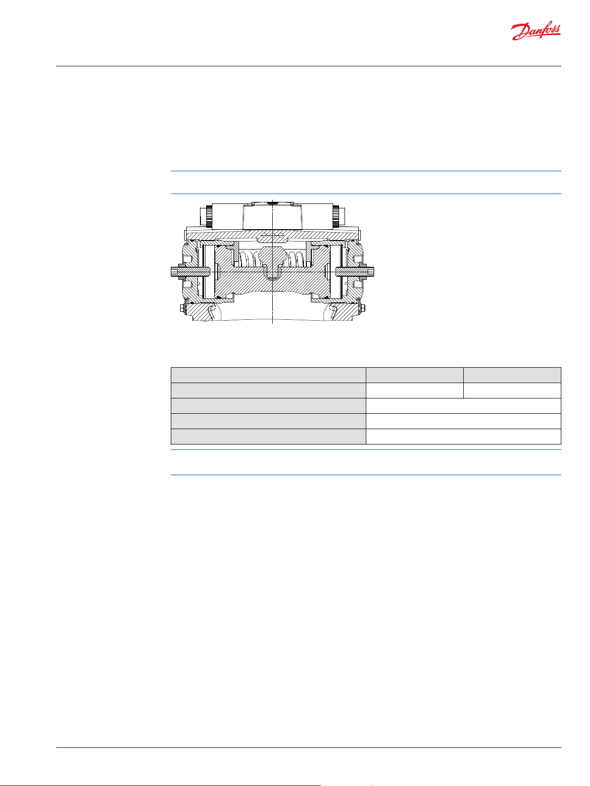
P003 266
Technical Information
H1P 045/053 Axial Piston Single Pumps
Control Options
Displacement Limiter
H1 pumps are designed with optional mechanical displacement (stroke) limiters factory set to max.
displacement. The maximum displacement of the pump can be set independently for forward and
reverse using the two adjustment screws to mechanically limit the travel of the servo piston down to 50%
displacement.
Adjustments under operating conditions may cause leakage. The adjustment screw can be completely
removed from the threaded bore if backed out to far.
H1P 045/053 Displacement Change (approximately)
Parameter Size 045 Size 053
1 turn of displacement limiter screw
Internal wrench size
External wrench size
Torque for external hex seal lock nut
5.1 cm3 [0.31 in3] 6.0 cm3 [0.37 in3]
4 mm
13 mm
23 N•m [204 lbf•in]
For more information, see H1 Axial Piston Pumps, Service Manual, AX152886482551, the section
“Displacement Limiter Adjustment”.
©
Danfoss | December 2021 BC152886483105en-001501 | 49
Page 50
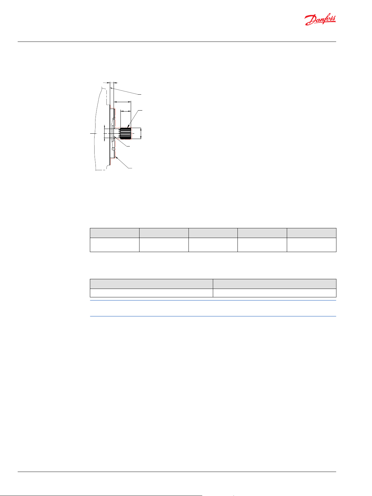
A
C
D
E
4
3
1
2
B
Technical Information
H1P 045/053 Axial Piston Single Pumps
Dimensions and Data
H1P 045/053 Input Shaft Option G1 (SAE C, 14 teeth)
1. Surface of mounting flange 101 – 2 per ISO 3019-1 (SAE B); to be paint free
2. Spline Data: 14 teeth, Pressure angle: 30°, Pitch: 12/24, Ø29.633 [1.167]; Fillet root side fit per ANSI
B92.1b, Class 6e
3. Coupling must not protrude beyond this point
4. Shaft to be paint free
Dimensions
A B C D
Ø31.58 ±0.09 [1.243
±0.004]
1)
Minimum active spline length for the specified torque ratings.
Ø25.72 ±0.12 [1.024
±0.005]
48.0 ±0.68 [1.89
±0.003]
1)
30.6 ±0.15 [1.205
±0.006]
E
8.0 ±0.8 [0.315 ±0.03]
Torque rating
Rated torque Maximum torque
534 N•m [4720 lb•in] 592 N•m [5240 lbf•in]
For definitions of maximum and rated torque values, refer to H1 Axial Piston Pumps Basic Information,
BC152886483968, the section “Shaft Torque Ratings and Spline Lubrication”.
50 | © Danfoss | December 2021 BC152886483105en-001501
Page 51

A
C
D
E
4
3
1
2
B
Technical Information
H1P 045/053 Axial Piston Single Pumps
Dimensions and Data
H1P 045/053 Input Shaft Option G4 (SAE B, 13 teeth)
1. Surface of mounting flange 101 – 2 per ISO 3019-1 (SAE B); to be paint free
2. Spline Data: 13 teeth, Pressure angle: 30°, Pitch: 16/32, Ø20.6375 [0.813]; Fillet root side fit per ANSI
B92.1b, Class 6e
3. Coupling must not protrude beyond this point
4. Shaft to be paint free
Dimensions
A B C D
Ø22.085 ±0.09 [0.869
±0.004]
1)
Minimum active spline length for the specified torque ratings.
Ø18.5 ±0.12 [0.728
±0.005]
33.0 ±0.68 [1.3
±0.003]
1)
16.5 ±0.15 [0.65
±0.006]
E
8.0 ±0.8 [0.315 ±0.03]
Torque rating
Rated torque Maximum torque
180 N•m [1600 lbf•in] 222 N•m [1970 lbf•in]
For definitions of maximum and rated torque values, refer to H1 Axial Piston Pumps Basic Information,
BC152886483968, the section “Shaft Torque Ratings and Spline Lubrication”.
©
Danfoss | December 2021 BC152886483105en-001501 | 51
Page 52

A
C
D
E
4
3
1
2
B
Technical Information
H1P 045/053 Axial Piston Single Pumps
Dimensions and Data
H1P 045/053 Input Shaft Option G5 (SAE B-B, 15 teeth)
1. Surface of mounting flange 101 – 2 per ISO 3019-1 (SAE B); to be paint free
2. Spline Data: 15 teeth, Pressure angle: 30°, Pitch: 16/32, Ø23.813 [0.938]; Fillet root side fit per ANSI
B92.1b, Class 6e
3. Coupling must not protrude beyond this point
4. Shaft to be paint free
Dimensions
A B C D
Ø25.23 ±0.09 [0.993
±0.004]
1)
Minimum active spline length for the specified torque ratings.
Ø21.98 ±0.12 [0.865
±0.005]
38.0 ±0.68 [1.496
±0.003]
1)
22.0 ±0.15 [0.866
±0.006]
E
8.0 ±0.8 [0.315 ±0.03]
Torque rating
Rated torque Maximum torque
277 N•m [2450 lbf•in] 370 N•m [3270 lbf•in]
For definitions of maximum and rated torque values, refer to H1 Axial Piston Pumps Basic Information,
BC152886483968, the section “Shaft Torque Ratings and Spline Lubrication”.
52 | © Danfoss | December 2021 BC152886483105en-001501
Page 53

2x 106.4 ±0.35
[4.189 ±0.014]
B
A
C
4
5
3
1
2
2x 53.2
±0.175
1.956 [0.077]
8.1 ±0.25
R0.8
max
[3.252]
+0.003
-0
∅
82.601
+0.076
-0
[3.489]
+0.005
-0
∅
88.621
+0.13
-0
C
Technical Information
H1P 045/053 Axial Piston Single Pumps
Dimensions and Data
H1P Auxiliary Mounting, Option H1 (SAE A, 11 teeth)
1. Auxiliary mounting pad for mating flange 82-2 per ISO 3019-1 (SAE A); Paint free
2. Spline Data: 11 teeth, Pressure angle: 30°, Pitch: 16/32, Ø17.463 [0.688]; Fillet root side fit per ANSI
B92.1b, Class 7e
3. O-ring seal required; Ref. Ø82.22 ID x 2.62, cross section
4. Thread: M10x1.5-6H; 15 [0.59] min. depth (4x)
5. Mating shaft and shaft shoulder must not protrude beyond this point
Dimensions and torque
A B C Max. Torque
57.2 min.; Shaft clearance 14.5 min.; Shaft clearance 239.6 ±2.5 [9.43 ±0.003] 296 N•m [2620 lbf•in]
For definitions of maximum and rated torque values, refer to H1 Axial Piston Pumps Basic Information,
BC152886483968, the section “Shaft Torque Ratings and Spline Lubrication”.
Caution
Standard pad cover is installed only to retain coupling during shipping. Do not operate pump without an
auxiliary pump or running cover installed.
©
Danfoss | December 2021 BC152886483105en-001501 | 53
Page 54

2x 106.4 ±0.35
[4.189 ±0.014]
B
A
C
4
5
3
1
2
2x 53.2
±0.175
1.956 [0.077]
8.1 ±0.25
R0.8
max
[3.252]
+0.003
-0
∅
82.601
+0.076
-0
[3.489]
+0.005
-0
∅
88.621
+0.13
-0
C
Technical Information
H1P 045/053 Axial Piston Single Pumps
Dimensions and Data
H1P Auxiliary Mounting, Option H2 (SAE A, 9 teeth)
1. Auxiliary mounting pad for mating flange 82-2 per ISO 3019-1 (SAE A); Paint free
2. Spline Data: 9 teeth, Pressure angle: 30°, Pitch: 16/32, Ø14.288 [0.563]; Fillet root side fit per ANSI
B92.1b, Class 7e
3. O-ring seal required; Ref. Ø82.22 ID x 2.62, cross section
4. Thread: M10x1.5-6H; 15 [0.59] min. depth (4x)
5. Mating shaft and shaft shoulder must not protrude beyond this point
Dimensions and torque
A B C Max. Torque
57.2 min.; Shaft clearance 14.5 min.; Shaft clearance 239.6 ±2.5 [9.43 ±0.003] 162 N•m [1430 lbf•in]
For definitions of maximum and rated torque values, refer to H1 Axial Piston Pumps Basic Information,
BC152886483968, the section “Shaft Torque Ratings and Spline Lubrication”.
Caution
Standard pad cover is installed only to retain coupling during shipping. Do not operate pump without an
auxiliary pump or running cover installed.
54 | © Danfoss | December 2021 BC152886483105en-001501
Page 55
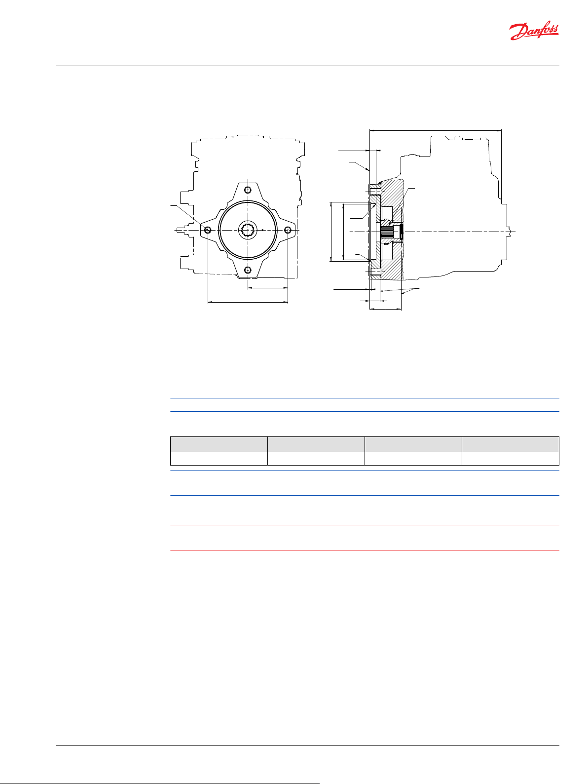
B
A
C
4
5
3
1
2
1.956 ±0.076
2x 146 ±0.35
2x 73
±0.175
R0.8
max
∅
101.651
∅
107.823
+0.076
-0
+0.13
-0
11.4 ±0.25
C
Technical Information
H1P 045/053 Axial Piston Single Pumps
Dimensions and Data
H1P Auxiliary Mounting, Option H3 (SAE B, 13 teeth)
1. Auxiliary mounting pad for mating flange 101-2 per ISO 3019-1 (SAE B); Paint free
2. Spline Data: 13 teeth, Pressure angle: 30°, Pitch: 16/32, Ø20.638 [0.813]; Fillet root side fit per ANSI
B92.1-1996, Class 6
3. O-ring seal required; Ref. Ø94.92 ID x 2.62, cross section
4. Thread: M12x1.75-6H; 19.75 [0.778] min. depth (4x)
5. Mating shaft and shaft shoulder must not protrude beyond this point
Bolt length > 19.75 mm could result in a leak or damage to the unit.
Dimensions and torque
A B C Max. Torque
57.2 min.; Shaft clearance 14.5 min.; Shaft clearance 239.6 ±2.5 [9.43 ±0.003] 395 N•m [3500 lbf•in]
For definitions of maximum and rated torque values, refer to H1 Axial Piston Pumps Basic Information,
BC152886483968, the section “Shaft Torque Ratings and Spline Lubrication”.
Caution
Standard pad cover is installed only to retain coupling during shipping. Do not operate pump without an
auxiliary pump or running cover installed.
©
Danfoss | December 2021 BC152886483105en-001501 | 55
Page 56

B
A
C
4
5
3
1
2
1.956 ±0.076
2x 146 ±0.35
2x 73
±0.175
R0.8
max
∅
101.651
∅
107.823
+0.076
-0
+0.13
-0
11.4 ±0.25
C
Technical Information
H1P 045/053 Axial Piston Single Pumps
Dimensions and Data
H1P Auxiliary Mounting, Option H5 (SAE B-B, 15 teeth)
1. Auxiliary mounting pad for mating flange 101-2 per ISO 3019-1 (SAE B); Paint free
2. Spline Data: 15 teeth, Pressure angle: 30°, Pitch: 16/32, Ø23.813 [0.938]; Fillet root side fit per ANSI
B92.1b, Class 7e
3. O-ring seal required; Ref. Ø94.92 ID x 2.62, cross section
4. Thread: M12x1.75-6H; 19.75 [0.778] min. depth (4x)
5. Mating shaft and shaft shoulder must not protrude beyond this point
Bolt length > 19.75 mm could result in a leak or damage to the unit.
Dimensions and torque
A B C Max. Torque
57.2 min.; Shaft clearance 14.5 min.; Shaft clearance 239.6 ±2.5 [9.43 ±0.003] 405 N•m [3580 lbf•in]
For definitions of maximum and rated torque values, refer to H1 Axial Piston Pumps Basic Information,
BC152886483968, the section “Shaft Torque Ratings and Spline Lubrication”.
Caution
Standard pad cover is installed only to retain coupling during shipping. Do not operate pump without an
auxiliary pump or running cover installed.
56 | © Danfoss | December 2021 BC152886483105en-001501
Page 57

2x 74.4 ±0.8
2x 106.3 ±0.8
2x (116.1)
1
2
186.32 ±1.2
59 ±0.859 ±0.8
4x 25.4 ±0.25
2x 11.9 ±0.25
B
A
90 ±0.8
Technical Information
H1P 045/053 Axial Piston Single Pumps
Dimensions and Data
H1P Displacement Limiter, Option B and D
1. Displacement limiter screw (2x)
2. Displacement limiter seal nut (2x)
Wrench size, torque
Wrench size for DL screw Wrench size for DL seal nut Torque
4 internal hex 13 external hex 24 N•m [18 lb•ft]
Please contact Danfoss representative for specific installation drawings.
H1P 045/053 End Cap, Options D6, D8, F2, F3
End cap, twin port Code 62, metric 4-bold flange
A/B System port Ø19 – 450 bar; Split flange boss per ISO 6162
M10x1.5; 18 full thread depth
©
Danfoss | December 2021 BC152886483105en-001501 | 57
Please contact Danfoss representative for specific installation drawings.
Page 58

107.6 ±0.8
125.2 ±2.5
1 ±0.5
9.7
0
-0.5
R0.8 max
45°±5°
101.6
0
-0.05
73 ±0.25
19.8 ±2.1
106 ±0.8
23 ±0.5
Z
Z
1
3
4
6
1
2x
1
2
3
6
5
4
Technical Information
H1P 045/053 Axial Piston Single Pumps
Dimensions and Data
Speed and temperature sensor, option H (for mounting flange option K)
1. Speed sensor connector DEUTSCH DTM04-6P, paint free
Connector DEUTSCH, 6-pin
Please contact Danfoss representative for specific installation drawings.
Pinout:
1. Speed signal 1
2. Direction signal
3. Speed signal 2
4. Ground (GND)
5. Supply
6. Temperature
58 | © Danfoss | December 2021 BC152886483105en-001501
Page 59

L4
B
A
E
F
MB
M14
S
M4
M5
M3
101.6
0
-0.05
0
238.2 max
173.3 max
129.7 max
2x 103 max
2x 64.2 ±0.8
38.0
88.5 max
AM3
2x 14.3
+0.25
Y
X
Y
X
L2
1
1
9.7
-0.5
Technical Information
H1P 045/053 Axial Piston Single Pumps
Dimensions and Data
Single Pump Ports
Ports per ISO 11 926-1
Port Description Size
A, B System ports 15∕16–12
L2, L4 Case drain ports 11∕16–12
MA, MB System A/B gauge ports
E/F Charge filtration ports
M3, AM3 Charge pressure port (AM3-Alternate)
M4, M5 Servo gauge port
M14 Case gauge port (EDC, FNR, NFPE)
S Charge inlet port 15∕16–12
1 Connector DEUTSCH DT04-2P, to be paint free
Please contact Danfoss representative for specific installation drawings.
9
∕16–18
7
∕8–14
9
∕16–18
7
∕16–20
7
∕16–20
©
Danfoss | December 2021 BC152886483105en-001501 | 59
Page 60

74.4 ±0.8
45°
±5°
101.6
0
-0.05
Paint free
R0.8 max
1 ±0.5
9.7
0
-0.5
19.8 ±2.1
2x 120 ±1.2
177.3 ±1.2
186.3 ±1.2
238 ±2.5
2x 147.3 ±1.2
2x 59 ±0.8
Name plate,
paint free
Mounting flange
Flange 101-2
Per ISO 3019-1 (SAE B)
2x 136.2 ±1.2
2x 110.5 ±1.2
41.1 ±0.8
74.38 min
Z
X
Y
A
A
B
B
C
C
89.5 ±0.8
Shaft
A-A (2x)
C
L
Shaf t
C
L
Shaft
C
L
91.2 ±0.8
89.5 ±0.8
B-B C-C
1
2
W (2:1)
Technical Information
H1P 045/053 Axial Piston Single Pumps
Dimensions and Data
H1P Dimensions
60 | © Danfoss | December 2021 BC152886483105en-001501
Page 61

(1)
2x 64.2 ±0.8
(128)
(29)
Approximate
center of gravity
173.3 ±2.588.5 ±1.5
(129.7)
81.5 ±0.8
Shaft
95.1 ±0.8
174.8 ±1.2
90 ±0.8
206 ±2.5
58 ±0.8
200 ±1.2
64 ±0.8
199.8 ±1.2
6 ±0.5
60 ±0.8
93.5 ±0.8
Charge filtration por
t
"F"
Po
rt
ISO 11926-1 - 7/8-14
To
filter
15°
(199.8)
93.5 ±0.8
Charge filtration por
t
"E"
Po
rt
ISO 11926-1 - 7/8-14
Fr
om filter
15°
(199.8)
F-F
E-E
Y
F
F
E E
D
D
C
L
Z
D-D
Technical Information
H1P 045/053 Axial Piston Single Pumps
Dimensions and Data
1 — Approximate center of gravity
©
Danfoss | December 2021 BC152886483105en-001501 | 61
Page 62

2x 73 ±0.25
2x ∅14.3
+0.25
-0.13
189.3 ±1.2
40 ±0.8
System A gauge port "MA"
Port ISO 11926-1 - 9/16-18
X
P700 33 051-1-3
CCW CW
C
Technical Information
H1P 045/053 Axial Piston Single Pumps
Dimensions and Data
1 — Other side screw head space
Caution
M12X1.75 or ½" screws with hardened washer (ASTM F436M or ISO 7089 300HV) must be used to mount
the pump. Using M14 screws may cause issues when mounting.
Please contact Danfoss representative for specific installation drawings.
62 | © Danfoss | December 2021 BC152886483105en-001501
Page 63

5
3
1
4
2
2x 64.2 ±0.8
206 ±0.8
X
X
1
2
Technical Information
H1P 045/053 Axial Piston Single Pumps
Dimensions and Data
Controls
EDC Options A2 and A3 (12/24 V)
1. Control solenoid connector C1 DEUTSCH DT04-2P, paint free
2. Control solenoid connector C2 DEUTSCH DT04-2P, paint free
3. Control Manual OverRide C1
4. Control Manual OverRide C2
5. Case gauge port M14 per ISO 1926-1: 7⁄16–20
Pin Assignment Alternative Pin Assignment
1 Supply OR 1 Ground
2 Ground 2 Supply
Please contact Danfoss representative for specific installation drawings.
©
Danfoss | December 2021 BC152886483105en-001501 | 63
Page 64
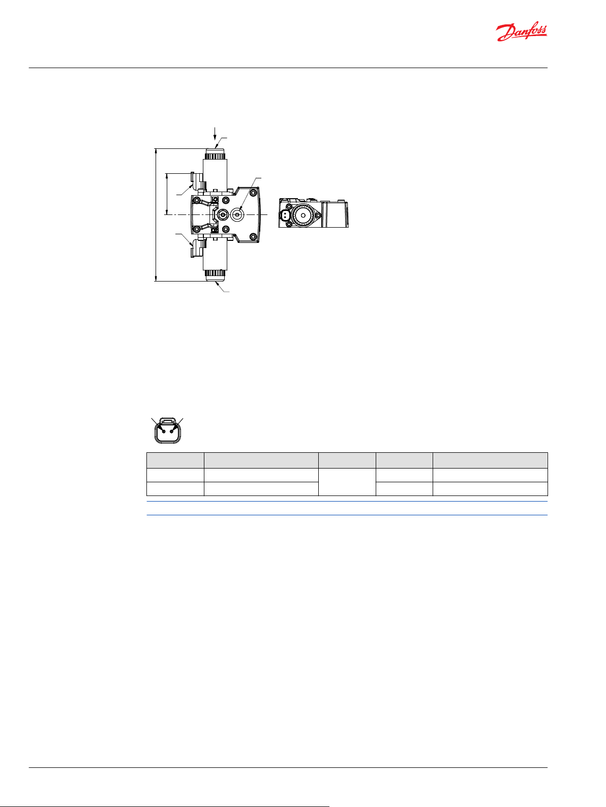
3
1
2
4
2x 64.2 ±0.8
209 ±0.8
5
X
X
2
1
Technical Information
H1P 045/053 Axial Piston Single Pumps
Dimensions and Data
EDC with MOR, Options A4 and A5 (12/24 V)
1. Control solenoid connector C1 DEUTSCH DT04-2P, paint free
2. Control solenoid connector C2 DEUTSCH DT04-2P, paint free
3. Control Manual OverRide C1
4. Control Manual OverRide C2
5. Case gauge port M14 per ISO 1926-1: 7⁄16–20
Depressing the plunger mechanically moves the control spool. Actuation allows full stroke pump
response as per coil and rotation dependent control logic.
Connector C1/C2: DEUTSCH DTM04-2P
Pin Assignment Alternative Pin Assignment
1 Supply OR 1 Ground
2 Ground 2 Supply
Please contact Danfoss representative for specific installation drawings.
64 | © Danfoss | December 2021 BC152886483105en-001501
Page 65

1
7
1
2
1
2
2
4
5
Key C
6.5 ±0.5
39.5 ±0.8
206 ±0.8
2x 64.2 ±0.8
X
X
6
3
Technical Information
H1P 045/053 Axial Piston Single Pumps
Dimensions and Data
EDC with CCO (key C), Options E7 and E8 (12/24 V)
1. Control solenoid connector C1 DEUTSCH DT04-2P, paint free
2. Control solenoid connector C2 DEUTSCH DT04-2P, paint free
3. Control Manual OverRide C1
4. Control Manual OverRide C2
5. Brake gauge port X7 per ISO 1926-1: 7⁄16–20
6. Case gauge port M14 per ISO 1926-1: 7⁄16–20
7. Control-Cut-Off with C-key connector C4 DEUTSCH DT04-2P, paint free
Pin Assignment Alternative Pin Assignment
1 Supply OR 1 Ground
2 Ground 2 Supply
Please contact Danfoss representative for specific installation drawings.
©
Danfoss | December 2021 BC152886483105en-001501 | 65
Page 66
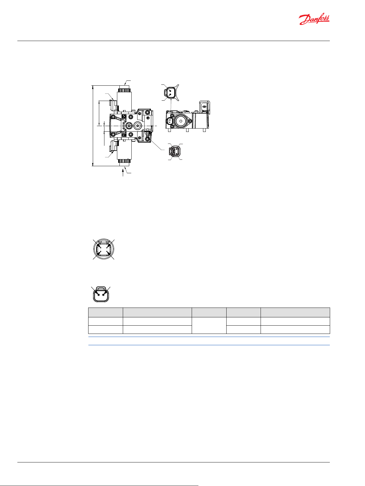
5
1
1
2
2
3
4
2
3
2x 64.2 ±0.8
206.2 ±0.8
4
1
14.5 ±1
X
X
2
3
4
1
2
1
Technical Information
H1P 045/053 Axial Piston Single Pumps
Dimensions and Data
EDC with ASNSR, Options: H2 and H3 (12/24 V)
1. Control solenoid connector C1 DEUTSCH DT04-2P, paint free
2. Control solenoid connector C2 DEUTSCH DT04-2P, paint free
3. Control Manual OverRide C1
4. Control Manual OverRide C2
5. Angle sensor connector S2 DEUTSCH DT04-4P, paint free
Connector DEUTSCH, 4-pin
4-pin assignment:
1. Ground (GND)
2. Not connected
3. Output signal 1 (SIG 1)
4. Supply (V+)
Connector C1/C2: DEUTSCH DTM04-2P
Pin Assignment Alternative Pin Assignment
1 Supply OR 1 Ground
2 Ground 2 Supply
Please contact Danfoss representative for specific installation drawings.
66 | © Danfoss | December 2021 BC152886483105en-001501
Page 67
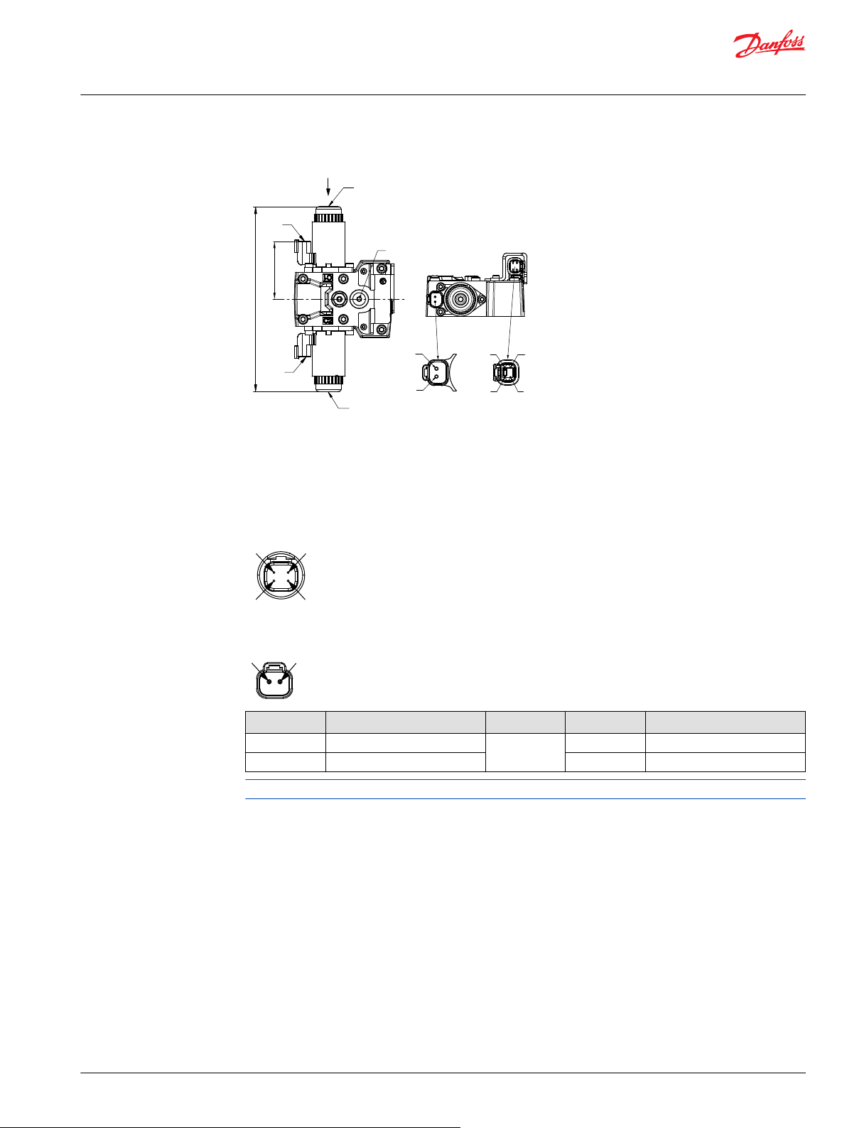
1
2
1
1
2
2
3
4
2x 64.2 ±0.8
209 ±2.5
5
3
4
X
X
2
3
4
1
2
1
Technical Information
H1P 045/053 Axial Piston Single Pumps
Dimensions and Data
EDC with MOR and ASNSR, Options H6 and H7 (12/24 V)
1. Control solenoid connector C1 DEUTSCH DT04-2P, paint free
2. Control solenoid connector C2 DEUTSCH DT04-2P, paint free
3. Control Manual OverRide C1
4. Control Manual OverRide C2
5. Case gauge port M14 per ISO 1926-1: 7⁄16–20
Connector DEUTSCH, 4-pin
4-pin assignment:
1. Ground (GND)
2. Not connected
3. Output signal 1 (SIG 1)
4. Supply (V+)
Connector C1/C2: DEUTSCH DTM04-2P
Pin Assignment Alternative Pin Assignment
1 Supply OR 1 Ground
2 Ground 2 Supply
Please contact Danfoss representative for specific installation drawings.
©
Danfoss | December 2021 BC152886483105en-001501 | 67
Page 68

7
6
2x 64.2 ±0.8
8 ±0.5
39.5 ±0.8
1
1
2
2
3
4
X
1
2
3
4
206 ±0.8
X
5
1
2
1
Key C
2
3
4
1
2
1
Technical Information
H1P 045/053 Axial Piston Single Pumps
Dimensions and Data
EDC with CCO and ASNSR, Options H8 and H9 (12/24 V)
1. Control solenoid connector C1 DEUTSCH DT04-2P, paint free
2. Control solenoid connector C2 DEUTSCH DT04-2P, paint free
3. Control Manual OverRide C1
4. Control Manual OverRide C2
5. Case gauge port M14 per ISO 1926-1: 7⁄16–20
6. Brake gauge port X7 per ISO 1926-1: 7⁄16–20
7. Control-Cut-Off with C-key connector C4 DEUTSCH DT04-2P, paint free
Depressing the plunger mechanically moves the control spool. Actuation allows full stroke pump
response as per coil and rotation dependent control logic.
Connector DEUTSCH, 4-pin
Angle sensor connector S2: DEUTSCH DTM04-4P
1. Ground (GND)
2. Not connected
3. Output signal 1 (SIG 1)
4. Supply (V+)
Connectors C1/C2/C4: DEUTSCH DTM04-2P
Pin Assignment Alternative Pin Assignment
1 Supply OR 1 Ground
2 Ground 2 Supply
Please contact Danfoss representative for specific installation drawings.
68 | © Danfoss | December 2021 BC152886483105en-001501
Page 69
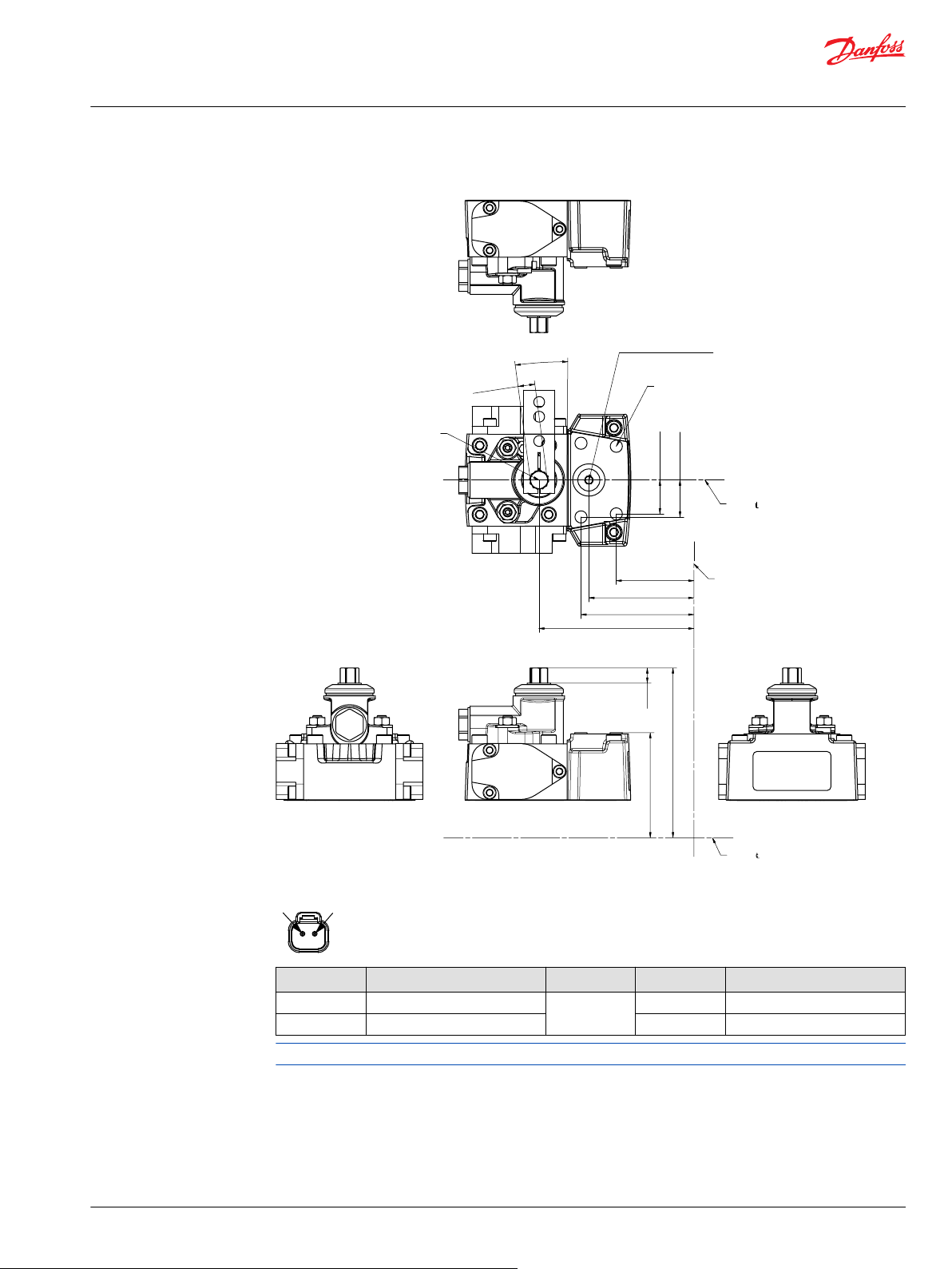
70102281-D10
Mounting flange
31.5±0.8
49.3±0.8
54.5±0.8
81.9±1.2
9.6
+1
214.7±2.5
171.8 ±1.2
Shaft
0
2x22±0.5
2x24±0.5
4x M6x1-6H thd.
9 min. full thd. depth
paint free
Case gauge port M14
ISO 11926-1 -7/16-20
Shaft
7.5±1°
3x11
-0.02
-0.08
Control handle shaft
2
1
Technical Information
H1P 045/053 Axial Piston Single Pumps
Dimensions and Data
MDC Option: M1
Connector DEUTSCH, 2-pin
Pin Assignment Alternative Pin Assignment
1 Supply OR 1 Ground
2 Ground 2 Supply
Please contact Danfoss representative for specific installation drawings.
©
Danfoss | December 2021 BC152886483105en-001501 | 69
Page 70
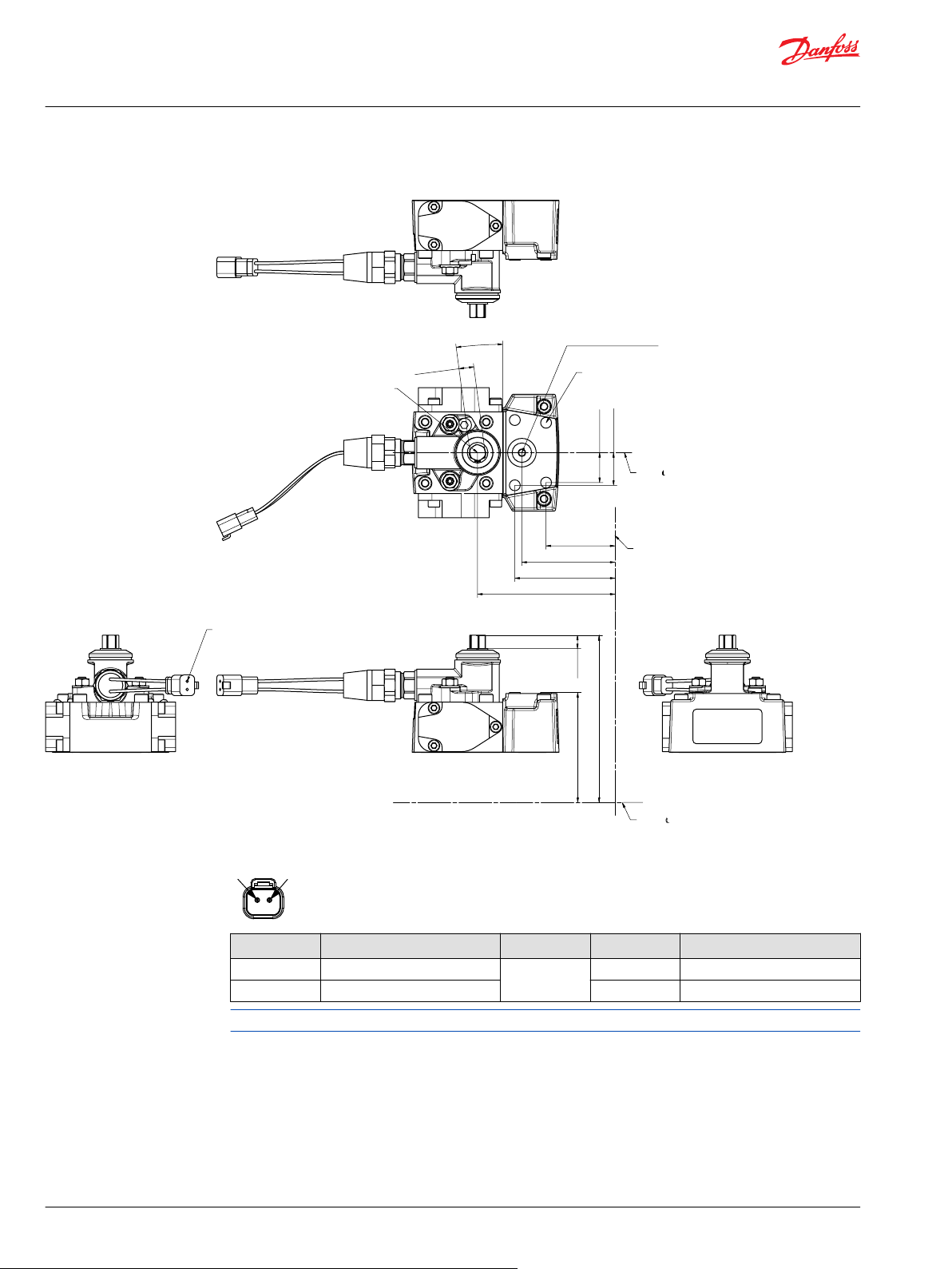
Mounting flange
2x22±0.5
2x24±0.5
7.5±1°
3x11
-0.02
-0.08
4x M6x1-6H thd.
9 min. full thd. depth
paint free
Neutral Start Switch connector:
Deutsch DT04-2P
paint free
Case gauge port M14
ISO 11926-1 -7/16-20
Shaft
Control handle shaft
Shaft
9.6
+1
0
045/053_70102283-D11
31.5±0.8
49.3±0.8
54.5±0.8
81.9±0.8
214.7±2.5
171.8 ±1.2
2
1
Technical Information
H1P 045/053 Axial Piston Single Pumps
Dimensions and Data
MDC with Neutral Start Switch Option: M2
Connector DEUTSCH, 2-pin
Pin Assignment Alternative Pin Assignment
1 Supply OR 1 Ground
2 Ground 2 Supply
Please contact Danfoss representative for specific installation drawings.
70 | © Danfoss | December 2021 BC152886483105en-001501
Page 71

Mounting flange
98.774±1.5
2x22±0.5
9.6
+1
2x24±0.5
7.5±1°
3x11
-0.02
-0.08
4x M6x1-6H thd.
9 min. full thd. depth
paint free
Shaft
Control handle shaft
Shaft
0
Control Cut Off connector C4:
Deutsch DT04-2P
paint free
Control Cut Off connector C4:
Deutsch DT04-2P
paint free
Case gauge port M14
ISO 11926-1 -7/16-20
Brake gauge port X7
ISO 11926-1 -7/16-20
045/053_70102283-D12
72.15±0.8
31.5±0.8
49.3±0.8
54.5±0.8
81.9±1.2
214.7±2.5
171.8 ±1.2
2
1
Technical Information
H1P 045/053 Axial Piston Single Pumps
Dimensions and Data
MDC with CCO, Options: M3, M4
Connector DEUTSCH, 2-pin
Pin Assignment Alternative Pin Assignment
1 Supply OR 1 Ground
2 Ground 2 Supply
©
Danfoss | December 2021 BC152886483105en-001501 | 71
Please contact Danfoss representative for specific installation drawings.
Page 72
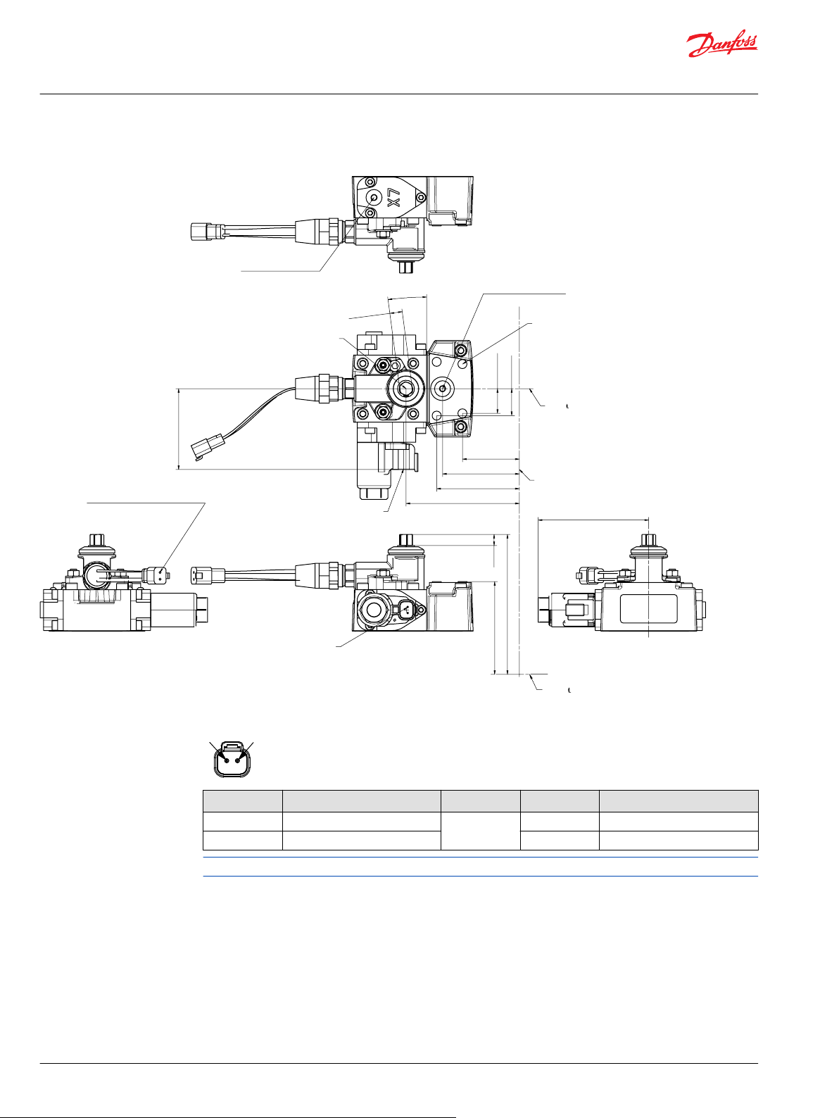
Mounting flange
2x22±0.5
2x24±0.5
7.5±1°
3x11
-0.02
-0.08
4x M6x1-6H thd.
9 min. full thd. depth
paint free
Neutral Start Switch connector:
Deutsch DT04-2P
paint free
Case gauge port M14
ISO 11926-1 -7/16-20
Shaft
Control handle shaft
Shaft
9.6
+1
0
Control Cut Off connector C4:
Deutsch DT04-2P
paint free
Brake gauge port X7
ISO 11926-1 -7/16-20
72.15±0.8
98.774±1.5
Control Cut Off connector C4:
Deutsch DT04-2P
paint free
045/053_70102283-D13
31.5±0.8
49.3±0.8
54.5±0.8
81.9±1.2
214.7±2.5
171.8 ±1.2
2
1
Technical Information
H1P 045/053 Axial Piston Single Pumps
Dimensions and Data
MDC with NSS and CCO Options: M5, M6
Connector DEUTSCH, 2-pin
Pin Assignment Alternative Pin Assignment
1 Supply OR 1 Ground
2 Ground 2 Supply
72 | © Danfoss | December 2021 BC152886483105en-001501
Please contact Danfoss representative for specific installation drawings.
Page 73

1
12
2
3
3
4x 87.4 ± 0.8
“A” ± 0.8
Mounting
flange
Shaft
clearance
“B” ± 1.2
2x “C” ± 1.2
2x “D” ± 0.8
2x “F” ± 2.5
4x “E” ±1.2
Shaft centerline
Mounting
flange
Technical Information
H1P 045/053 Axial Piston Single Pumps
Dimensions and Data
HDC, Options: T1, T2
Ports
Item Description
1 Control signal pressure inlet port "X1"
2 Control signal pressure inlet port "X2"
3 Case gauge port "M14"
Dimensions in mm [in]
Size A B C D E F
H1T 45/53 58 [2.3] 325.7 [12.8] 291.7 [11.5] 92 [3.6] 147.3 [5.8] 173.3 [6.8]
H1T 60/68 69.2 [2.7] 365.8 [14.4] 331.8 [13.1] 103.2 [4.1] 147.9 [5.8] 173.9 [6.8]
Port ISO 11926-1 - 9/16-18UNF-2B
Port ISO 11926-1 - 9/16-18UNF-2B
Port ISO 11926-1 - 7/16-20UNF-2
©
Danfoss | December 2021 BC152886483105en-001501 | 73
Page 74

3
4
5
1
2
2x 64.2 ±0.8
209 ±0.8
2
1
Technical Information
H1P 045/053 Axial Piston Single Pumps
Dimensions and Data
NFPE with MOR, Options: N1, N2 (12/24 V)
Non-Feedback Proportional Electric control with Manual Over Ride options N1 (12 V) and N2 (24 V).
1. Control solenoid connector C1 DEUTSCH DT04-2P, paint free
2. Control solenoid connector C2 DEUTSCH DT04-2P, paint free
3. Control Manual OverRide C1
4. Control Manual OverRide C2
5. Case gauge port M14 per ISO 1926-1: 7⁄16–20
Control solenoid connectors C1/C2 DEUTSCH DTM04-2P pin/assignment
Pin Assignment Alternative Pin Assignment
1 Supply OR 1 Ground
2 Ground 2 Supply
Please contact Danfoss representative for specific installation drawings.
74 | © Danfoss | December 2021 BC152886483105en-001501
Page 75

2x 64.2 ±0.8
8 ±0.5
28.8 ±0.5
39.5 ±0.8
A – A
A
A
6
5
1
2
209 ±2.5
4
3
2
3
4
1
2
1
Technical Information
H1P 045/053 Axial Piston Single Pumps
Dimensions and Data
NFPE with MOR, CCO, ASNSR, Options: N3, N4 (12/24 V)
Non-Feedback Proportional Electric control with Control-Cut-Off valve with key C, Manual Over Ride and
Angle Sensor, options N3 (12 V) and N4 (24 V).
1. Control solenoid connector C1 DEUTSCH DT04-2P, paint free
2. Control solenoid connector C2 DEUTSCH DT04-2P, paint free
3. Control Manual OverRide C1
4. Control Manual OverRide C2
5. Case gauge port M14 per ISO 1926-1: 7⁄16–20
6. Control-Cut-Off with C-key connector C4 DEUTSCH DT04-2P, paint free
Depressing the plunger mechanically moves the control spool. Actuation allows full stroke pump
response as per coil and rotation dependent control logic.
Connector DEUTSCH, 4-pin
Pin/assignment:
1. Ground (GND)
2. Output Signal 2 (SIG2) – Secondary (redundant)
3. Output signal 1 (SIG 1)
4. Supply (V+)
Control solenoid connectors C1/C2/C4 DEUTSCH DTM04-2P pin/assignment
Pin Assignment Alternative Pin Assignment
1 Supply OR 1 Ground
2 Ground 2 Supply
Please contact Danfoss representative for specific installation drawings.
©
Danfoss | December 2021 BC152886483105en-001501 | 75
Page 76

2x 64.2 ±0.8
28.8 ±0.5
A–A
A
A
3
4
1
2
209 ±2.5
5
2
3
4
1
2
1
Technical Information
H1P 045/053 Axial Piston Single Pumps
Dimensions and Data
NFPE with MOR and ASNSR, Options: N5, N6 (12/24 V)
Non-Feedback Proportional Electric control with Manual Over Ride and Angle Sensor, options N5 (12 V)
and N6 (24 V).
1. Control solenoid connector C1 DEUTSCH DT04-2P, paint free
2. Control solenoid connector C2 DEUTSCH DT04-2P, paint free
3. Control Manual OverRide C1
4. Control Manual OverRide C2
5. Angle sensor connector S2 DEUTSCH DT04-4P, paint free
Connector DEUTSCH, 4-pin
Pin/assignment:
1. Ground (GND)
2. Output Signal 2 (SIG2) – Secondary (redundant)
3. Output signal 1 (SIG 1)
4. Supply (V+)
Control solenoid connectors C1/C2 DEUTSCH 2-pin/assignment
Pin Assignment Alternative Pin Assignment
1 Supply OR 1 Ground
2 Ground 2 Supply
Please contact Danfoss representative for specific installation drawings.
76 | © Danfoss | December 2021 BC152886483105en-001501
Page 77

1
3
2x 64.2 ±0.8
6.5 ±0.5
39.5 ±0.8
209 ±2.5
2
7
4
5
6
2
3
4
1
2
1
Technical Information
H1P 045/053 Axial Piston Single Pumps
Dimensions and Data
NFPE with MOR and CCO, Options: N7, N8 (12/24 V)
Non Feedback Proportional Electric control with Manual Over Ride and Control-Cut-Off valve key C,
options N7 (12 V) and N8 (24 V).
1. Control solenoid connector C1 DEUTSCH DT04-2P, paint free
2. Control solenoid connector C2 DEUTSCH DT04-2P, paint free
3. Control Manual OverRide C1
4. Control Manual OverRide C2
5. Brake gauge port X7 per ISO 1926-1: 7⁄16–20
6. Case gauge port M14 per ISO 1926-1: 7⁄16–20
7. Control-Cut-Off with C-key connector C4 DEUTSCH DT04-2P, paint free
Depressing the plunger mechanically moves the control spool. Actuation allows full stroke pump
response as per coil and rotation dependent control logic.
Connector DEUTSCH, 4-pin
Pin/assignment:
1. Ground (GND)
2. Output Signal 2 (SIG2) – Secondary (redundant)
3. Output signal 1 (SIG 1)
4. Supply (V+)
Control solenoid connectors C1/C2 DEUTSCH DTM04-2P pin assignment
Pin Assignment Alternative Pin Assignment
1 Supply OR 1 Ground
2 Ground 2 Supply
Please contact Danfoss representative for specific installation drawings.
©
Danfoss | December 2021 BC152886483105en-001501 | 77
Page 78

61.2 ±0.8 61.2 ±0.8
30.2
±
0.8
C1
CAN
CC2
CC2
C2
V
209 max
V
2
CAN
CC1
CC2
CCC3
CCC3
220 ±2.5
110 ±1.5
1
Technical Information
H1P 045/053 Axial Piston Single Pumps
Dimensions and Data
Automotive control (AC)
1 Plug removing can cause contamination issues
2 PPU wire harness is factory installed to speed sensor
Connectors description
Port Description
C1 and C2
1. Control manual override C1
2. Control Manual Override C2
CC1
CC2
CC3
CAN
Port A control connector DEUTSCH DTM04-12P; paint free
Port B control connector DEUTSCH DTM04-12P; paint free
Control connector DEUTSCH DT06-2S; paint free; For using connector, the plug may be removed.
Control connector DEUTSCH DTM04-3P; paint free; For using connector, the plug may be removed.
Please contact Danfoss representative for specific installation drawings.
78 | © Danfoss | December 2021 BC152886483105en-001501
Page 79

CC3
CC3
PPC
CAN
C1
C2
PPU
CC2
CC1
CAN
PPC
CC2
206 ±2.5
2x 61.2 ±0.8
30.2 ±0.8
9.6 ±0.8
74.5 ±0.1
2
1
1 2 3
1
2
3
6
5
4
1 2 3 4 5 6
12
11
10
9 8 7
Technical Information
H1P 045/053 Axial Piston Single Pumps
Dimensions and Data
AC connectors dimensions
PPU wire harness is factory installed to speed sensor.
CC3 CAN PPC
Connector DEUTSCH, 2-pin
1. Digital output A1 (+)
2. Digital output A2 (-)
Connector DEUTSCH, 12-pin
Connector DEUTSCH, 3-pin
1. CAN High
2. CAN Low
3. CAN Shield
CC1
1. Battery (-)
2. Battery (+)
3. Sensor (+)
4. Sensor (-)
5. Motor rpm input (frequency)
6. Forward input (digital)
7. Reverse input (digital)
8. Sensor (+)
9. Sensor (-)
10. Drive pedal input (analog –
11. Drive pedal input (analog – red)
12. Neural input (digital)
nominal)
Connector DEUTSCH, 6-pin
1. Sensor A (+)
2. Analog input A
3. Sensor A (-)
4. Sensor B (-)
5. Analog input B
6. Sensor B (+)
CC2
1. Inch input (analog – red)
2. Mode switch B input (digital –
nominal)
3. Motor prop/PCOR driver
4. Motor direction input (analog)
5. Sensor (+)
6. Sensor (-)
7. Inch input (analog – nominal)
8. Motor BPD driver
9. Digital output B2 (-)
10. Digital output B1 (+)
11. Mode switch A input (digital)
12. Mode switch B input (digital – red)
©
Danfoss | December 2021 BC152886483105en-001501 | 79
Page 80
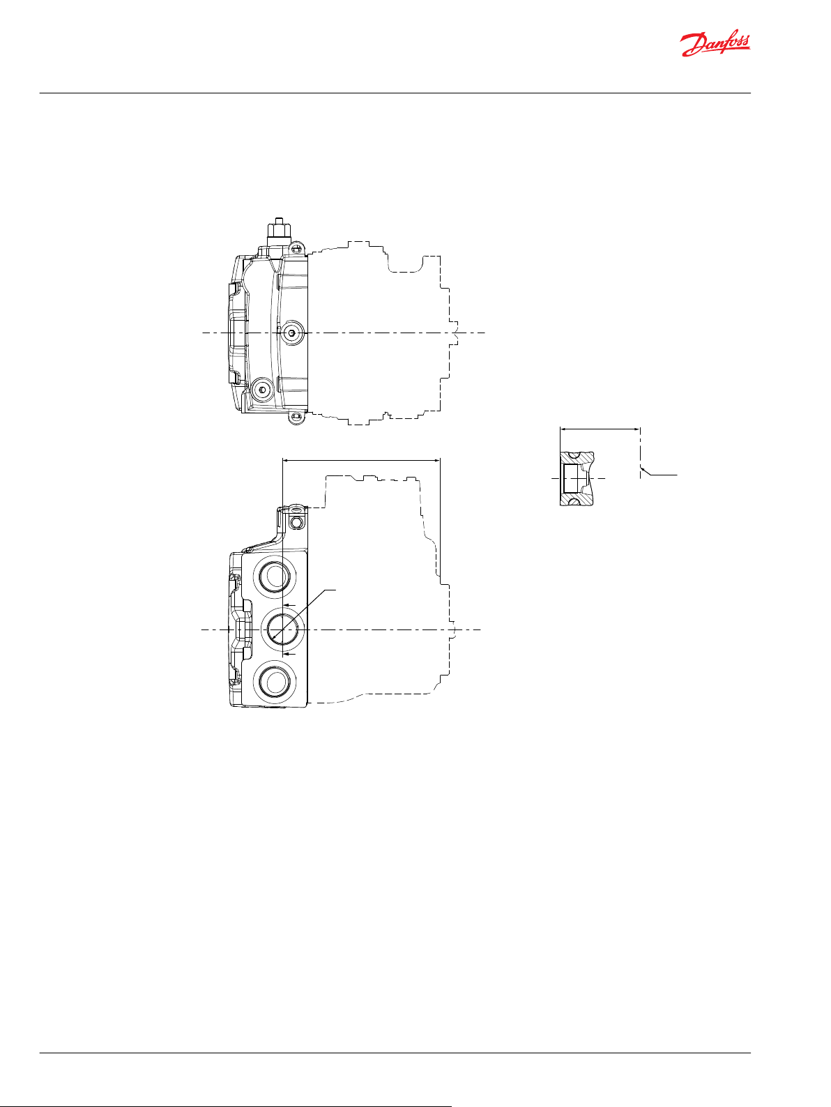
A-A
S
177.3 ±1.2
89.5 ±0.8
Shaft
C
L
A
A
Technical Information
H1P 045/053 Axial Piston Single Pumps
Dimensions and Data
Filtration
H1P 45/53 Suction Filtration Option L
S Charge inlet port per ISO 1926-1; 1 5/16-12
80 | © Danfoss | December 2021 BC152886483105en-001501
Page 81

C
C
C-C
C
L
177.3 ±1.2
89.5 ±0.8
1
S
F
(199.8)
93.5 ±0.8
15°
93.5 ±0.8
E
15°
(199.8)
199.8 ±1.2
60 ±0.8
6 ±0.5
A-A
B-B
A A
B B
Technical Information
H1P 045/053 Axial Piston Single Pumps
Dimensions and Data
H1P 45/53 Full Flow Charge Pressure Filtration Option P
Remote full flow charge pressure filtration, option P (for endcap option F)
E Charge filtration port per ISO 11926-1; 7/8-14 from filter
F Charge filtration port per ISO 11926-1; 7/8-14 to filter
S Charge inlet port per ISO 11926-1; 5/16-12
©
Danfoss | December 2021 BC152886483105en-001501 | 81
Page 82

93.5 ±0.8
E
15°
(199.8)
199.8 ±1.2
60 ±0.8
6 ±0.5
A-A
A A
Technical Information
H1P 045/053 Axial Piston Single Pumps
Dimensions and Data
External Full Flow Charge Pressure Filtration, Option E
E Charge filtration ports per ISO 11926-1: 7∕8–14 from filter
Please contact Danfoss representative for specific installation drawings.
82 | © Danfoss | December 2021 BC152886483105en-001501
Page 83

Danfoss
Power Solutions GmbH & Co. OHG
Krokamp 35
D-24539 Neumünster, Germany
Phone: +49 4321 871 0
Danfoss
Power Solutions ApS
Nordborgvej 81
DK-6430 Nordborg, Denmark
Phone: +45 7488 2222
Danfoss
Power Solutions (US) Company
2800 East 13th Street
Ames, IA 50010, USA
Phone: +1 515 239 6000
Danfoss
Power Solutions Trading
(Shanghai) Co., Ltd.
Building #22, No. 1000 Jin Hai Rd
Jin Qiao, Pudong New District
Shanghai, China 201206
Phone: +86 21 2080 6201
Products we offer:
Hydro-Gear
www.hydro-gear.com
Daikin-Sauer-Danfoss
www.daikin-sauer-danfoss.com
Cartridge valves
•
DCV directional control
•
valves
Electric converters
•
Electric machines
•
Electric motors
•
Gear motors
•
Gear pumps
•
Hydraulic integrated
•
circuits (HICs)
Hydrostatic motors
•
Hydrostatic pumps
•
Orbital motors
•
PLUS+1® controllers
•
PLUS+1® displays
•
PLUS+1® joysticks and
•
pedals
PLUS+1® operator
•
interfaces
PLUS+1® sensors
•
PLUS+1® software
•
PLUS+1® software services,
•
support and training
Position controls and
•
sensors
PVG proportional valves
•
Steering components and
•
systems
Telematics
•
Danfoss Power Solutions is a global manufacturer and supplier of high-quality hydraulic and
electric components. We specialize in providing state-of-the-art technology and solutions
that excel in the harsh operating conditions of the mobile off-highway market as well as the
marine sector. Building on our extensive applications expertise, we work closely with you to
ensure exceptional performance for a broad range of applications. We help you and other
customers around the world speed up system development, reduce costs and bring vehicles
and vessels to market faster.
Danfoss Power Solutions – your strongest partner in mobile hydraulics and mobile
electrification.
Go to www.danfoss.com for further product information.
We offer you expert worldwide support for ensuring the best possible solutions for
outstanding performance. And with an extensive network of Global Service Partners, we also
provide you with comprehensive global service for all of our components.
Local address:
Danfoss can accept no responsibility for possible errors in catalogues, brochures and other printed material. Danfoss reserves the right to alter its products without notice. This also applies to products
already on order provided that such alterations can be made without subsequent changes being necessary in specifications already agreed.
All trademarks in this material are property of the respective companies. Danfoss and the Danfoss logotype are trademarks of Danfoss A/S. All rights reserved.
©
Danfoss | December 2021 BC152886483105en-001501
 Loading...