

Service Kit Instructions
Charge pressure ranges
*
gauge reading minus the case pressure
po
min
of 50° C (120° F)
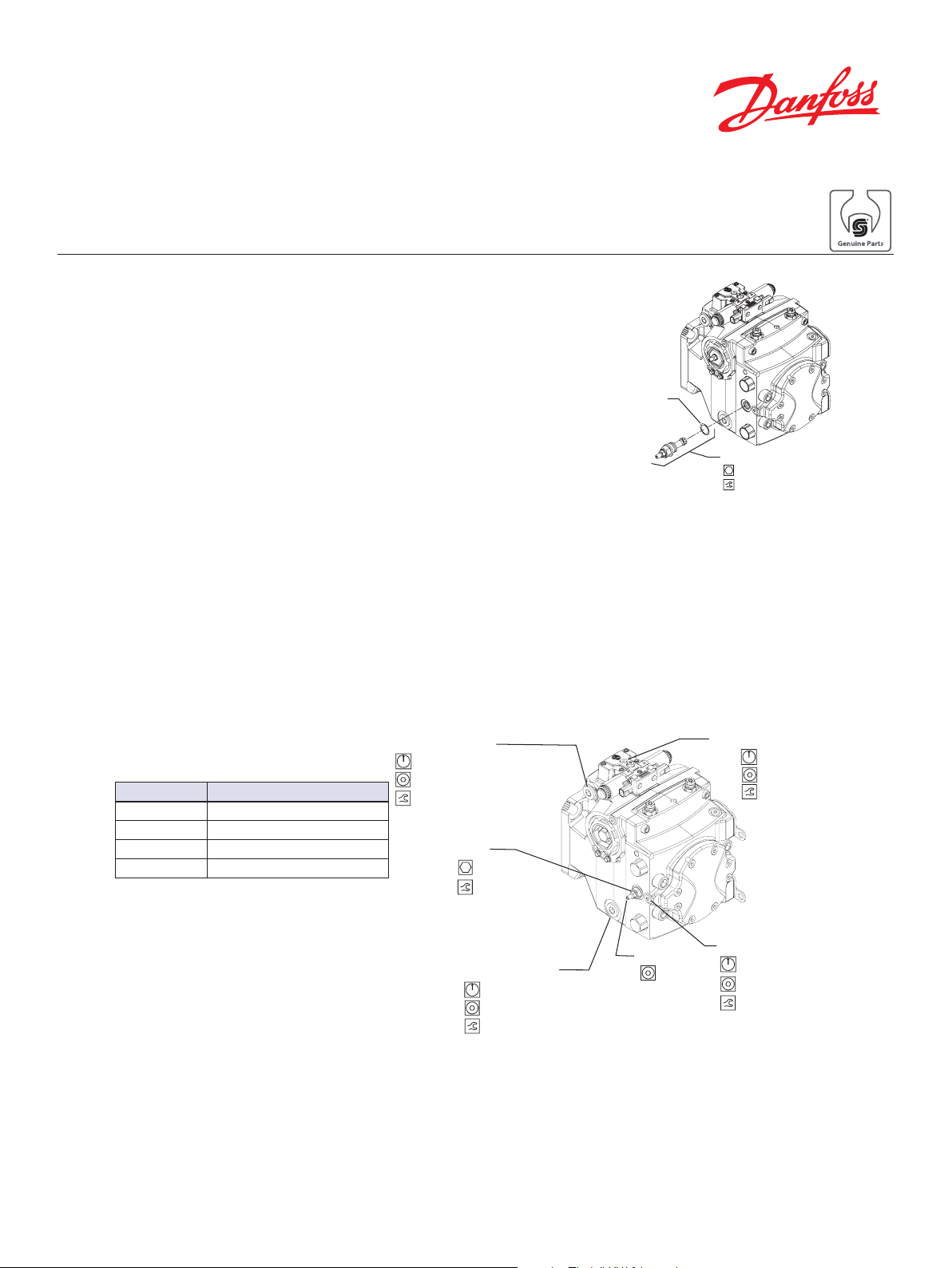
Case drain port L4
Charge pressure gauge port M3
D065 Optional construction port
V024
P106 115E
H1P pumps
Charge pressure relief valve replacement procedure
CHARGE PRESSURE
RELIEF VALVE REMOVAL
CHARGE PRESSURE
RELIEF VALVE
INSTALLATION
CHARGE PRESSURE
RELIEF VALVE
ADJUSTMENT
1. Clean pump externally with clean solvent to
remove debris.
2. Using a 24 mm wrench, remove the charge
pressure relief valve. (V030)
1. Lubricate the external O-ring (V024) using
petroleum jelly.
V030
2. Install the new charge pressure relief valve.
Using a 24 mm socket, torque to 52 N•m [38
24 mm
52 N•m
[38 lbf•ft]
lbf•ft]
1. Install a 50 bar [1000 psi] pressure gage in charge pressure gauge port M3 (next to the adjustment screw). Install a 10 bar [100 psi] gauge at one of the case drain pressure ports L1, L2,
L3, or L4. Operate the system with the pump in neutral (zero displacement) when measuring
charge pressure.
2. The table shows the acceptable pump charge pressure range for some nominal charge relief
valve settings (refer to the model code located on the serial number plate). These pressures
assume 1800 pump rpm and a reservoir temperature of 50°C (120°F), and are referenced to
case pressure.
Model code Measured charge pressure*
20 bar [290 psi] ± 1.5 bar [21.8 psi]
24 bar [348 psi] ± 1.5 bar [21.8 psi]
26 bar [377 psi] ± 1.5 bar [21.8 psi]
30 bar [345 psi] ± 1.5 bar [21.8 psi]
This is the actual charge pressure port
rt gauge reading. Factory set at 1800
-1
Listed pressures assume a
(rpm) with a reservoir temperature
pump speed of 1800 rpm. At
higher pump speeds (with
higher charge flows) the
charge pressure will rise over
the rated settings.
© Danfoss, 2013 AN262753055643en-000102 | 70342065 • Rev 0102 • March 2018 1
0 - 10 bar [0 - 100 psi]
9/16 inch
95-136 N•m [70-100 lbf•ft]
V022
19 mm
40 N•m [30 lbf•ft]
0 - 10 bar [0 - 100 psi]
3/16 inch
11-14 N•m [8-10 lbf•ft]
Case drain port L2
0 - 10 bar [0 - 100 psi]
5/8 inch
95-136 N•m [70-100 lbf•ft]
V020
6 mm
0 - 50 bar [0 - 1000 psi]
1/4 inch
20-27 N•m [15-20 lbf•ft]
3. Adjust valve. Clockwise rotation of the adjusting screw (V020) increases the setting, and
counterclockwise rotation decreases the setting (at a rate of approximately 3.9 bar [56.6 psi]
per turn).
4. Torque locknut (V022) to 40 N•m [30 lbf•ft] using a 19mm socket.
5. When desired charge pressure is achieved, remove the gauges and plug the ports.
P104 466E
 Loading...