

Page 1
User Manual
PLUS+1® Compliant
H1 EDC Angle Sensor Function Block
www.danfoss.com
Page 2
User Manual
PLUS+1® Compliant H1 EDC Angle Sensor Function Block
Revision history Table of revisions
Date Changed Rev
September 2021 Resolved isses with status and fault signals 0204
March 2020 Changed document number from 'AQ00000218' to 'AQ220986485489' 0203
December 2018 NV_Cal_Min, NV_Cal_Mid, and NV_Cal_Max for displacement 0202
February 2017 First edition 0201
2 | © Danfoss | September 2021 AQ220986485489en-000204
Page 3

User Manual
PLUS+1® Compliant H1 EDC Angle Sensor Function Block
Contents
H1 EDC Angle Sensor Function Block
Inputs....................................................................................................................................................................................................4
Outputs................................................................................................................................................................................................ 5
Diagnostic Signals............................................................................................................................................................................6
[Remove this section] Function Block Connections.............................................................................................................6
Status Logic........................................................................................................................................................................................ 7
Fault Logic...........................................................................................................................................................................................7
Parameter Values..............................................................................................................................................................................8
Relationship of Input to Output Signals...................................................................................................................................9
[Remove this section] Para Input..............................................................................................................................................11
xxx Unmodified H1_EDC_Ang_Snsr Function Block................................................................................................... 11
xxx Modified H1_EDC_Ang_Snsr Function Block......................................................................................................... 12
Identical Function Blocks Need Different Namespace Values to Successfully Compile...................................... 12
Change Namespace Value.....................................................................................................................................................13
MC Controller Configurations................................................................................................................................................... 14
Configure MFIn for SIG Input................................................................................................................................................14
Configure DigAn for SIG Input.............................................................................................................................................15
Configure AnIn for SIG input................................................................................................................................................ 15
SC Controller Configurations.....................................................................................................................................................16
Configure MFIn for SIG input................................................................................................................................................16
Configure DigAn for SIG input.............................................................................................................................................17
Pre-Made Service Screens...........................................................................................................................................................18
H1 EDC Angle Sensor Screen................................................................................................................................................18
H1 EDC Angle Sensor Calibration Screen ........................................................................................................................20
©
Danfoss | September 2021 AQ220986485489en-000204 | 3
Page 4
User Manual
PLUS+1® Compliant H1 EDC Angle Sensor Function Block
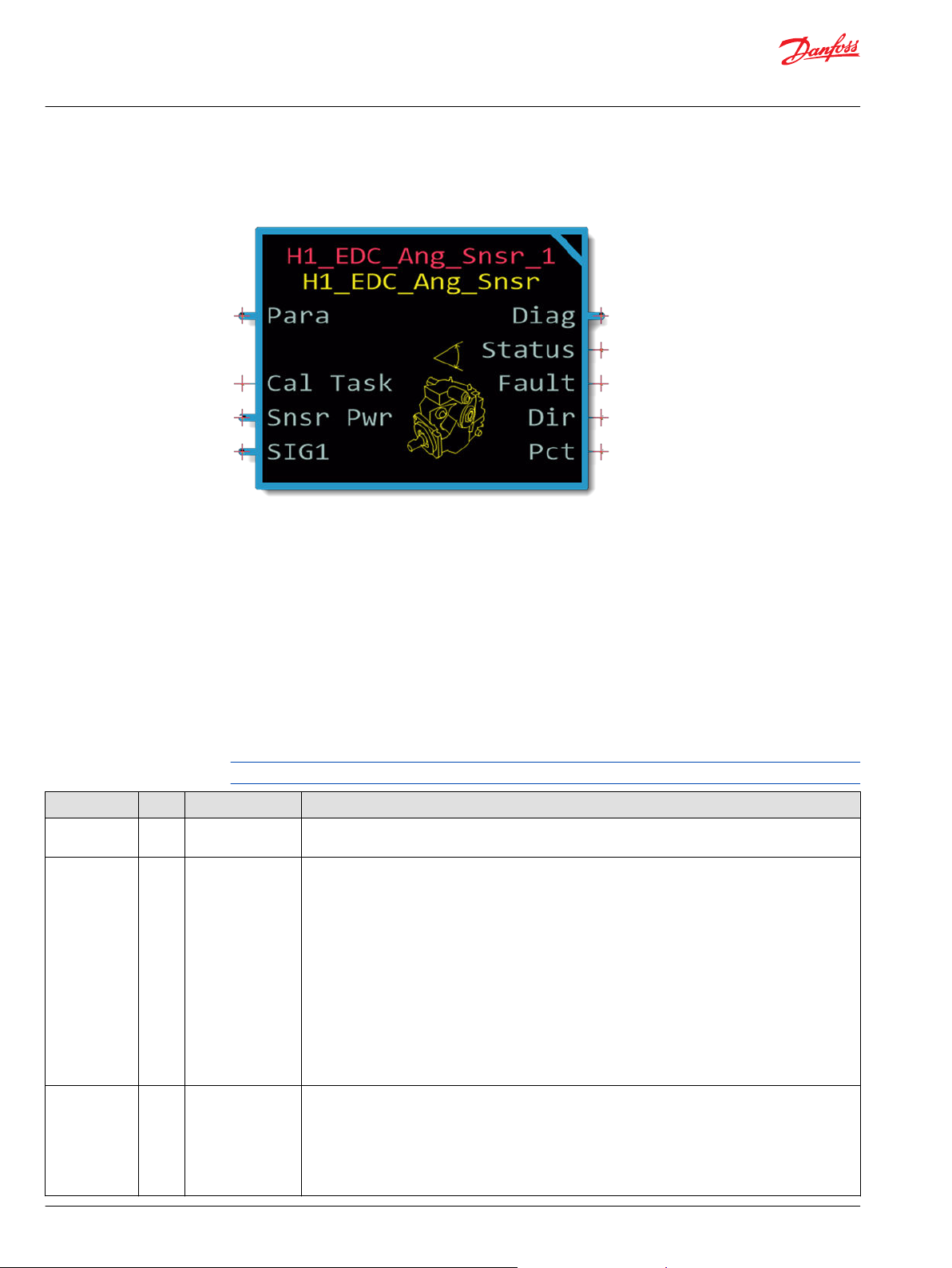
H1 EDC Angle Sensor Function Block
The H1_EDC_Ang_Snsr function block monitors the angle sensor output from an H1 EDC Angle Sensor
installed in an H1 EDC pump.
The output of this function block provides your application with the pump's:
Swash plate angle position in percent.
•
Direction of pump flow.
•
See:
Function Block Connections for more about this function block's connections and signals.
•
Identical Function Blocks Need Different Namespace Values to Successfully Compile if you are using more
•
than one of these function blocks in your application.
Inputs
The following section describes input signals to the H1 EDC Angle Sensor function block.
This function block ships with its NV_Cal_Min, and NV_Cal_Max values set at 0.
Item Type Range Description [Unit]
Para Bus —— Input for external parameter values.
See Para Input for more information.
Cal Task U8 0–5 Controls the function block's calibration process:
•
0 = Disable calibration.
•
1 = Calibrate the percentage of Snsr Pwr that the SIG1 input must reach for the pump to output its
minimum displacement. Store this percentage as the NV_Cal_Min value.
For example, if the pump outputs its maximum reverse displacement with SIG1 input at 1000 mV
and a Snsr Pwr of 5000 mV, then the function block stores an NV_Cal_Min value of 2000 (20.00%).
•
2 = Calibrate the percentage of Snsr Pwr that the SIG1 input must reach for the pump to output its
maximum displacement. Store this percentage as the NV_Cal_Max value.
For example, if the pump outputs its maximum forward displacement with SIG1 input at 4000 mV
and a Snsr Pwr of 5000 mV, then the function block stores an NV_Cal_Max value of 5000 (50.00%).
•
3 = Set NV_Cal_Min and NV_Cal_Max to their default values.
•
4 = Clear calibration values.
Snsr Pwr Bus —— Voltage supplied to the swash plate angle sensor.
The function block uses the Snsr Pwr and SIG1 signals and the NV_Cal_Min and NV_Cal_Max values
to make a ratiometric calculation of the swash plate angle sensor's position and its faults.
The function block receives this value through either a Volt signal or a Voltage signal:
•
On Legacy MC controllers, the value inputs through the Volt signal.
•
On SC and Non-Legacy MC controllers, the value inputs through the Voltage signal.
4 | © Danfoss | September 2021 AQ220986485489en-000204
Page 5
User Manual
PLUS+1® Compliant H1 EDC Angle Sensor Function Block
H1 EDC Angle Sensor Function Block
Item Type Range Description [Unit]
U16 4750–5250 Voltage supplied to the swash plate angle sensor.
Volt
Voltage
SIG1 Bus —— Signal from the swash plate angle sensor that indicates, through voltage, the position of the pump
Voltage U16 0-5250 Voltage read from the swash plate angle sensor
SIG2 Bus —— Signal from the swash plate angle sensor that indicates, through voltage, the position of the pump
Voltage U16 0-5250 Voltage read from the swash plate angle sensor
U16 4750–5250 Voltage supplied to the swash plate angle sensor.
Volt U16 0-5250 Voltage read from the swash plate angle sensor.
Volt U16 0-5250 Voltage read from the swash plate angle sensor.
[mV]
[mV]
swash plate.
The function block uses the Snsr Pwr, SIG1, and SIG2 signals and the NV_Cal_Min and NV_Cal_Max
values to make a ratiometric calculation of the swash plate angle sensor's position and its faults.
The function block receives this value through either a Volt signal or a Voltage signal:
•
On Legacy MC controllers, the value inputs through the Volt signal.
•
On SC and Non-Legacy MC controllers, the value inputs through the Voltage signal.
[mV]
[mV]
swash plate.
The function block uses the Snsr Pwr, SIG1, and SIG2 signals and to make a ratiometric calculation of
the swash plate angle sensor's position and its faults.
The function block receives this value through either a Volt signal or a Voltage signal:
•
On Legacy MC controllers, the value inputs through the Volt signal.
•
On SC and Non-Legacy MC controllers, the value inputs through the Voltage signal.
[mV]
[mV]
Outputs
This section describes output signals of the H1 EDC Angle Sensor function block.
Item Type Range Description [Unit]
Status U16 —— Reports the status of the function block.
0x0000: Status is OK.
0x0001: Cal_Min value is not calibrated.
0x0002: Cal_Mid value is not calibrated.
0x0004: Cal_Max value is not calibrated.
0x0008: Invalid setup or a parameter is out of range.
Fault U16 —— Reports the faults of the function block.
0x0000 = No fault.
0x8001 = SIG1 input is too low.
0x8002 = SIG1 input is too high.
0x8004 = SIG1 input is at Sensor Power.
0x8008 = SIG1 input is at Ground.
0x8010 = An input is out of range.
0x8040 = Redundant signal indicates error.
Pct U16 0–10,000 Swash plate angle as a percentage.
•
0 = Minimum swash plate angle.
•
10000 = Maximum swash plate angle.
[0.01%]
Displ
Diag Bus —— Contains input, parameter, diagnostic, and output signals.
U16 0–300 Pump displacement based on measured angle.
©
Danfoss | September 2021 AQ220986485489en-000204 | 5
Page 6
User Manual
PLUS+1® Compliant H1 EDC Angle Sensor Function Block
H1 EDC Angle Sensor Function Block
Diagnostic Signals
Entering the Checkpoints page on the second level of the function block provides access to the function
block’s diagnostic signals.
It contains checkpoints on input, output and internal signals. Only the internal signals are explained here.
Input and output signals are described in other chapters.
Item Type Range Description
Input_Ratio U16 0-10,000 The ratiometric calculation value of the SIG1 voltage as a percentage of Snsr Pwr.
StatExp U16 0x00-0x7F Status Expanded: Bitwise signal where each bit corresponds to a parameter that is invalid.
T = Parameter invalid.
•
F = Parameter OK.
•
Bit0: Cal_Task
Bit1: NV_Cal_Max
Bit2: NV_Cal_Min
Bit3: FltDetectTm
Bit4: Dband
Bit5: Min_Displ
Bit6: Max_Displ
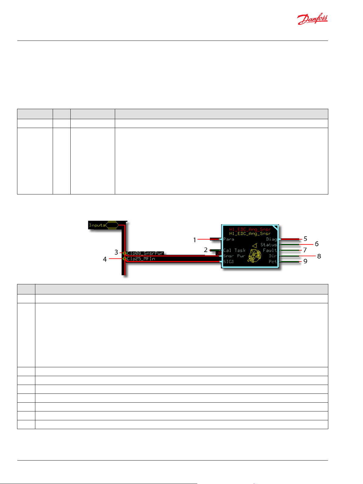
[Remove this section] Function Block Connections
Item Description
1 Input for external parameter values.
2
3 Voltage supplied to the swash plate angle sensor.
4 Signal from the swash plate angle sensor that indicates, through voltage, the position of the pump swash plate.
5 Diagnostic signals of the function block.
6 Reports the status of the function block.
7 Reports the faults of the function block.
8 Swash plate direction indicator.
9 Swash plate sensor angle as a percentage.
0 = Disable calibration.
•
1 = Calibrate the percentage of Snsr Pwr that the SIG1 input must reach for the pump to output its maximum forward displacement. Store
•
this percentage as the NV_Cal_Max value.
2 = Calibrate the percentage of Snsr Pwr that the SIG1 input must reach for the pump to output its maximum reverse displacement. Store
•
this percentage as the NV_Cal_Min value.
3 = Calibrate the percentage of Snsr Pwr that the SIG1 input must reach for the pump to output its neutral displacement. Store this
•
percentage as the NV_Cal_Mid value.
4 = Set NV_Cal_Min, NV_Cal_Mid and NV_Cal_Max to their default values.
•
5 = Clear calibration values.
•
6 | © Danfoss | September 2021 AQ220986485489en-000204
Page 7
User Manual
PLUS+1® Compliant H1 EDC Angle Sensor Function Block
H1 EDC Angle Sensor Function Block
Status Logic
This topic describes how the function block indicates status.
Status Hex
Status is OK. 0x0000 0000 Not applicable. Correction not necessary.
Cal_Min value is not calibrated. 0x0001 0001
Cal_Mid value is not calibrated.
Cal_Max value is not calibrated. 0x0004 0100 Calibrate the Cal_Max value.
Invalid setup or a parameter is
out of range.
0x0002 0010 Calibrate the Cal_Mid value.
0x0008 1000 Correct the setup; return parameter values
Binary Response Correction
Pct output = 0.
•
Displ output = Min_Displ.
•
Calibrate the Cal_Min value.
to within their valid ranges.
Fault Logic
This topic describes how the function block indicates fault logic.
Fault Hex Binary Response Correction
No fault. 0x0000 00000000 Not applicable. Not applicable.
SIG1 input is too low. 0x8001 00000001
SIG1 input is too high. 0x8002 00000010
SIG1 input equals Snsr Pwr input. 0x8004
SIG1 input is at ground. 0x8008 00001000
An input signal is out of range. 0x8010 00010000
Redundant signal indicates error. 0x8040 01000000
00000100
•
Pct output = 0.
•
Displ output = Min_Displ .
Repair the hardware fault.
©
Danfoss | September 2021 AQ220986485489en-000204 | 7
Page 8

User Manual
PLUS+1® Compliant H1 EDC Angle Sensor Function Block
H1 EDC Angle Sensor Function Block
Parameter Values
As needed, enter the H1_EDC_Ang_Snsr function block to change its parameter values.
Item Type Range Description
FltDetectTm U16 0–10000 Sets the time before the function block:
•
Reports a fault that it has detected.
•
Stops reporting a fault that has been cleared.
1000 = 1000 ms.
Dband U16 0–5000 Deadband applied to NV_Cal_Min and NV_Cal_Max value before scaling the SIG1 input to the Pct
output.
5000 = 50.00%
Min_Displ U16 0–300 Minimum pump displacement.
Max_Displ U16 0–300 Maximum pump displacement.
8 | © Danfoss | September 2021 AQ220986485489en-000204
Page 9

User Manual
PLUS+1® Compliant H1 EDC Angle Sensor Function Block
H1 EDC Angle Sensor Function Block
Relationship of Input to Output Signals
Without a Deadband value
Figure details
Item Description
1. The NV_Cal_Min value sets the percentage of Snsr Pwr at which the SIG1 input to the function block produces minimum Pct output. In this
example:
•
The Snsr Pwr is 5000 mV.
•
The NV_Cal_Min value is 8000 (80.00%). (80% of 5000 mV is 4000 mV).
•
A 4000 mV SIG1 input to the function block produces minimum Pct output.
2. The NV_Cal_Max value sets the percentage of Snsr Pwr at which the SIG1 input to the function block maximum Pct output. In this example:
•
TheSnsr Pwr is 5000 mV.
•
The NV_Cal_Maxvalue is 5000 (50.00%). (50% of 5000 mV is 2500 mV).
A 2500 mV SIG1 input to the function block produces maximum Pct output.
©
Danfoss | September 2021 AQ220986485489en-000204 | 9
Page 10

User Manual
PLUS+1® Compliant H1 EDC Angle Sensor Function Block
H1 EDC Angle Sensor Function Block
With a Deadband value
Figure details
Item Description
1. The Dband value sets the width of an upper deadband that extends above the SIG1 input that produces the maximum output. The function
block calculates this deadband as a percentage of the difference between the SIG1 input voltage that produces minimum Pct output and the
SIG1 input voltage that produces maximum Pct output. In this example, with Snsr Pwr at 5000 mV:
•
The Dband is 2000 (20.00%).
•
The difference between the threshold SIG1 and the maximum SIG1 voltages is 1500 mV (4000-2500 = 1500).
•
The lower deadband is 300 mV wide. (20.00% of 1500 mV is 300 mV.)
2.
The Dband value sets the width of a lower deadband that extends below the SIG1 input that produces the minimum pump output. The
function block calculates this deadband as a percentage of the difference between the SIG1 input voltage that produces minimum Pct output
and the SIG1 input voltage that produces maximum Pct output. In this example, with Snsr Pwr at 5000 mV:
•
The Dband is 2000 (20.50%).
•
The difference between the threshold SIG1 and the maximum SIG1 voltages is 1500 mV (4000-2500 = 1500).
•
The deadband is 300 mV wide. (20.00% of 1500 mV is 300 mV.)
10 | © Danfoss | September 2021 AQ220986485489en-000204
Page 11

User Manual
PLUS+1® Compliant H1 EDC Angle Sensor Function Block
H1 EDC Angle Sensor Function Block
[Remove this section] Para Input
Use the Para input to input parameter values to this function block from an external source.
xxx Unmodified H1_EDC_Ang_Snsr Function Block
The following figure shows the inner page of an unmodified H1_EDC_Ang_Snsr function block.
The FltDetectTm and the Dband values are both inside this page.
©
Danfoss | September 2021 AQ220986485489en-000204 | 11
Page 12

User Manual
PLUS+1® Compliant H1 EDC Angle Sensor Function Block
H1 EDC Angle Sensor Function Block
xxx Modified H1_EDC_Ang_Snsr Function Block
The following figure shows the inner page of an H1_EDC_Ang_Snsr function block after modification.
The Para input now routes the FltDetectTm and Dband values into the page. These values originate
from outside the function block.
Identical Function Blocks Need Different Namespace Values to Successfully Compile
If you use the same function block more than once in an application, you must change each function
block’s namespace value to avoid compiler errors.
All function blocks contain Advanced Checkpoint with Namespace components that enable the PLUS+1
Service Tool to read block input and output values.
Some function blocks contain non-volatile memory components that store function block operating
parameters.
Both these components use memory names (“aliases”) to allocate memory. Identical memory names
cause compiler errors.
The namespace value adds a unique prefix to each component name to avoid errors. Keep each
namespace value short to save controller memory.
12 | © Danfoss | September 2021 AQ220986485489en-000204
®
Page 13

User Manual
PLUS+1® Compliant H1 EDC Angle Sensor Function Block
H1 EDC Angle Sensor Function Block
Change Namespace Value
To successfully compile your application, change the namespace value for function blocks that are used
more than once in an application.
1. In the PLUS+1® GUIDE menu bar, click the Query/Change button.
2. Click on the function block whose namespace you want to set to a unique value.
The Edit Page window opens.
3. In the Edit Page window, enter a meaningful Namespace value.
Namespace values are case-sensitive.
•
To save controller memory, use a short namespace value.
•
4. Press Enter.
5. Repeat these steps to enter unique namespace values for other identical function blocks.
©
Danfoss | September 2021 AQ220986485489en-000204 | 13
Page 14
User Manual
PLUS+1® Compliant H1 EDC Angle Sensor Function Block
H1 EDC Angle Sensor Function Block
MC Controller Configurations
This function block receives its SIG1 signals through the controller's inputs.
The following table identifies the controller inputs that you must modify to input these signals.
Function Block
Input
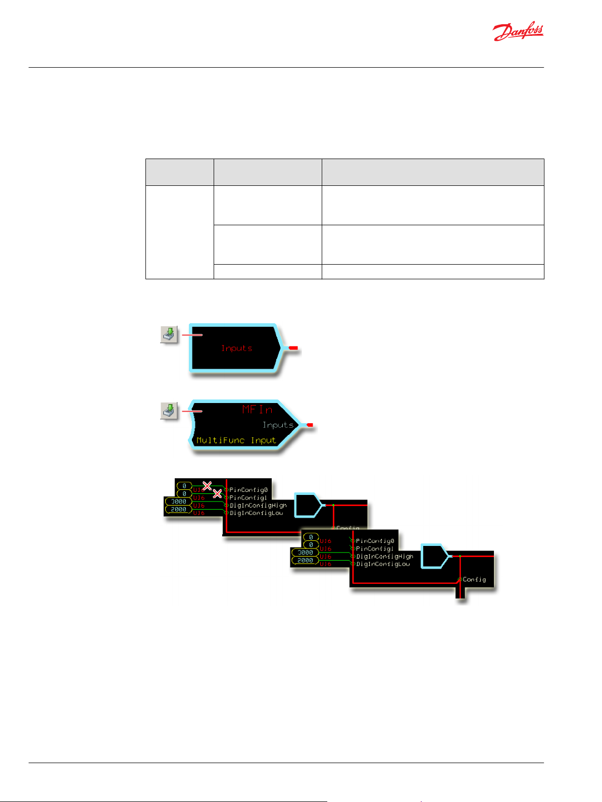
SIG1 MFIn Delete the:
Compatible Controller Input
Type
DigAn Delete the:
AnIn Delete the PinConfig route.
Controller Input Configuration Action
•
PinConfig0 route.
•
PinConfig1 route.
•
PinConfig0 route.
•
PinConfig1 route.
Configure MFIn for SIG Input
1. In the PLUS+1® GUIDE template, enter the Inputs page.
2. Enter the MFIn that receives the input signal.
3. Make the changes that are shown in the following figure.
14 | © Danfoss | September 2021 AQ220986485489en-000204
Page 15

User Manual
PLUS+1® Compliant H1 EDC Angle Sensor Function Block
H1 EDC Angle Sensor Function Block
Configure DigAn for SIG Input
1. In the PLUS+1® GUIDE template, enter the Inputs page.
2. Enter the DigAn page that receives the input signal.
3. Make the changes that are shown in the following figure.
Configure AnIn for SIG input
1. In the PLUS+1® GUIDE template, enter the Inputs page.
2. Enter the AnIn that receives the input signal.
3. Make the changes that are shown in the following figure.
©
Danfoss | September 2021 AQ220986485489en-000204 | 15
Page 16

User Manual
PLUS+1® Compliant H1 EDC Angle Sensor Function Block
H1 EDC Angle Sensor Function Block
SC Controller Configurations
This function block receives its SIG1 signals through the controller's inputs.
The following table identifies the controller inputs that you must modify to input these signals.
Function Block
Input
SIG1 MFIn Delete the:
Configure MFIn for SIG input
1. In the PLUS+1® GUIDE template, enter the Inputs page.
2. Enter the MFIn that receives the input signal.
Compatible Controller Input
Type
DigAn Delete the:
Controller Input Configuration Action
Bias route.
•
Range route.
•
InputMode route.
•
Bias route.
•
Range route.
•
3. Make the changes that are shown in the following figure.
16 | © Danfoss | September 2021 AQ220986485489en-000204
Page 17

User Manual
PLUS+1® Compliant H1 EDC Angle Sensor Function Block
H1 EDC Angle Sensor Function Block
Configure DigAn for SIG input
1. In the PLUS+1® GUIDE template, enter the Inputs page.
2. Enter the DigAn that receives the input signal.
3. Make the changes that are shown in the following figure.
©
Danfoss | September 2021 AQ220986485489en-000204 | 17
Page 18

User Manual
PLUS+1® Compliant H1 EDC Angle Sensor Function Block
H1 EDC Angle Sensor Function Block
Pre-Made Service Screens
Pre-made service screens provide overviews of the H1_EDC_Ang_Snsr function block.
H1 EDC Angle Sensor Screen
This screen gives an overview of the H1_EDC_Ang_Snsr function block.
The green check mark next to the parameters indicates whether the associated parameter is within its
defined range. If the parameter is out of range a red X is displayed. If any parameter has an error, Status
displays the Parameter OOR (Out of Range) as an active fault.
Item Units Description
Input Signal (Input) mV Signal from the swash plate angle sensor that indicates, through voltage, the position of the pump swash plate.
Sensor Supply (Input) mV Voltage supplied to the swash plate angle sensor.
Input Signal Ratio
(Diagnostic)
Fault Detect Time
(Parameter)
% Input Signal reported as a percentage of Sensor Supply.
ms Sets the time before the function block reports a fault that it has detected, and stops reporting a fault that has
been cleared.
18 | © Danfoss | September 2021 AQ220986485489en-000204
Page 19

User Manual
PLUS+1® Compliant H1 EDC Angle Sensor Function Block
H1 EDC Angle Sensor Function Block
Item Units Description
Cal Task (Parameter) % Controls the function block’s calibration process:
0 = Disable calibration.
1 = Calibrate the percentage of Snsr Pwr that the SIG1 input must reach for the pump to output its
2 = Calibrate the percentage of Snsr Pwr that the SIG1 input must reach for the pump to output its
3 = Calibrate the percentage of Snsr Pwr that the SIG1 input must reach for the pump to output its
4 = Set NV_Cal_Min, NV_Cal_Mid, and NV_Cal_Max to their default values.
5 = Clear calibration values.
Cal Min (Parameter) % Reports the EEPROM value for Cal_Min.
Cal Mid (Parameter) % Reports the EEPROM value for Cal_Mid.
Cal Max (Parameter) % Reports the EEPROM value for Cal_Max.
Angle Percent (Output) % Swash plate angle as a percentage.
-100.00 = Maximum reverse swash plate angle.
0 = Neutral swash plate angle.
100.00 = Maximum Forward swash plate angle.
Direction (Output) -- Swash plate direction indicator.
-1 = Reverse
0 = Neutral
1 = Forward
Status (Output) -- Reports the status of the function block.
Fault (Output) -- Reports the faults of the function block.
Input and Parameter Faults -- Lists the active faults reported by the block.
maximum forward displacement. Store this percentage as the NV_Cal_Max value. For example,
if the pump outputs its maximum displacement with SIG1 input at 4000 mV and a Snsr Pwr of
5000 mV, then the function block stores an NV_Cal_Max value of 8000 (80.00%).
maximum reverse displacement. Store this percentage as the NV_Cal_Min value. For example, if
the pump outputs its maximum displacement with SIG1 input at 1000 mV and a Snsr Pwr of
5000 mV, then the function block stores an NV_Cal_Min value of 2000 (20.00%).
neutral displacement. Store this percentage as the NV_Cal_Mid value. For example, if the pump
outputs its maximum displacement with SIG1 input at 2500 mV and a Snsr Pwr of 5000 mV, then
the function block stores an NV_Cal_Min value of 5000 (50.00%).
©
Danfoss | September 2021 AQ220986485489en-000204 | 19
Page 20

User Manual
PLUS+1® Compliant H1 EDC Angle Sensor Function Block
H1 EDC Angle Sensor Function Block
H1 EDC Angle Sensor Calibration Screen
This screen gives an overview of the H1 EDC Angle Sensor function block calibration procedure.
The green check mark next to the parameters indicates whether the associated parameter is with its
defined range. If the parameter is out of range a red X will be displayed. If any parameter has an error
Status will display the Parameter OOR (Out of Range) as an active fault.
Screen item description
Item Units Description
Input Signal Ratio
(Diagnostic)
Cal Task (Parameter) % Controls the function block’s calibration process:
Cal Min (Parameter) % Reports the EEPROM value for Cal_Min.
Cal Mid (Parameter) % Reports the EEPROM value for Cal_Mid.
Cal Max (Parameter) % Reports the EEPROM value for Cal_Max.
Cal Rev Max Db (Parameter) % Deadband adjustment applied to Cal_Min before scaling input to output.
% Input Signal reported as a percentage of Sensor Supply.
0= Disable calibration.
1=
2=
3=
4= Set NV_Cal_Min, NV_Cal_Mid, and NV_Cal_Max to their default values.
5= Clear calibration values.
Calibrate the percentage of Snsr Pwr that the SIG1 input must reach for the pump to output its
maximum forward displacement.
Store this percentage as the NV_Cal_Max value. For example, if the pump outputs its maximum
displacement with SIG1 input at 4000 mV and a Snsr Pwr of 5000 mV, then the function block
stores an NV_Cal_Max value of 8000 (80.00%).
Calibrate the percentage of Snsr Pwr that the SIG1 input must reach for the pump to output its
maximum reverse displacement.
Store this percentage as the NV_Cal_Min value. For example, if the pump outputs its maximum
displacement with SIG1 input at 1000 mV and a Snsr Pwr of 5000 mV, then the function block
stores an NV_Cal_Min value of 2000 (20.00%).
Calibrate the percentage of Snsr Pwr that the SIG1 input must reach for the pump to output its
neutral displacement. Store this percentage as the NV_Cal_Mid value.
For example, if the pump outputs its maximum displacement with SIG1 input at 2500 mV and a
Snsr Pwr of 5000 mV, then the function block stores an NV_Cal_Min value of 5000 (50.00%).
20 | © Danfoss | September 2021 AQ220986485489en-000204
Page 21

User Manual
PLUS+1® Compliant H1 EDC Angle Sensor Function Block
H1 EDC Angle Sensor Function Block
Screen item description (continued)
Item Units Description
Cal Rev Min Db (Parameter) % Deadband adjustment applied to Cal_Mid in the reverse direction before scaling input to output.
Cal Fwd Min Db (Parameter) % Deadband adjustment applied to Cal_Mid in the forward direction before scaling input to output.
Cal Fwd Max Db (Parameter) % Deadband adjustment applied to Cal_Max before scaling input to output.
Angle Percent (Output) % Swash plate angle as a percentage.
-100.00= Maximum reverse swash plate angle.
0= Neutral swash plate angle.
100.00= Maximum Forward swash plate angle.
Direction (Output) -- Swash plate direction indicator.
-1= Reverse
0= Neutral
1= Forward
Status (Output) -- Reports the status of the function block. See Status Logic on page 7 for more information.
Fault (Output) -- Reports the faults of the function block. See Status Logic on page 7 for more information.
©
Danfoss | September 2021 AQ220986485489en-000204 | 21
Page 22

Danfoss
Power Solutions GmbH & Co. OHG
Krokamp 35
D-24539 Neumünster, Germany
Phone: +49 4321 871 0
Danfoss
Power Solutions ApS
Nordborgvej 81
DK-6430 Nordborg, Denmark
Phone: +45 7488 2222
Danfoss
Power Solutions (US) Company
2800 East 13th Street
Ames, IA 50010, USA
Phone: +1 515 239 6000
Danfoss
Power Solutions Trading
(Shanghai) Co., Ltd.
Building #22, No. 1000 Jin Hai Rd
Jin Qiao, Pudong New District
Shanghai, China 201206
Phone: +86 21 2080 6201
Products we offer:
Hydro-Gear
www.hydro-gear.com
Daikin-Sauer-Danfoss
www.daikin-sauer-danfoss.com
Cartridge valves
•
DCV directional control
•
valves
Electric converters
•
Electric machines
•
Electric motors
•
Gear motors
•
Gear pumps
•
Hydraulic integrated
•
circuits (HICs)
Hydrostatic motors
•
Hydrostatic pumps
•
Orbital motors
•
PLUS+1® controllers
•
PLUS+1® displays
•
PLUS+1® joysticks and
•
pedals
PLUS+1® operator
•
interfaces
PLUS+1® sensors
•
PLUS+1® software
•
PLUS+1® software services,
•
support and training
Position controls and
•
sensors
PVG proportional valves
•
Steering components and
•
systems
Telematics
•
Danfoss Power Solutions is a global manufacturer and supplier of high-quality hydraulic and
electric components. We specialize in providing state-of-the-art technology and solutions
that excel in the harsh operating conditions of the mobile off-highway market as well as the
marine sector. Building on our extensive applications expertise, we work closely with you to
ensure exceptional performance for a broad range of applications. We help you and other
customers around the world speed up system development, reduce costs and bring vehicles
and vessels to market faster.
Danfoss Power Solutions – your strongest partner in mobile hydraulics and mobile
electrification.
Go to www.danfoss.com for further product information.
We offer you expert worldwide support for ensuring the best possible solutions for
outstanding performance. And with an extensive network of Global Service Partners, we also
provide you with comprehensive global service for all of our components.
Local address:
Danfoss can accept no responsibility for possible errors in catalogues, brochures and other printed material. Danfoss reserves the right to alter its products without notice. This also applies to products
already on order provided that such alterations can be made without subsequent changes being necessary in specifications already agreed.
All trademarks in this material are property of the respective companies. Danfoss and the Danfoss logotype are trademarks of Danfoss A/S. All rights reserved.
©
Danfoss | September 2021 AQ220986485489en-000204
 Loading...