

Page 1
Parts Manual
H1B 250cc
Bent Axis Motor
www.danfoss.com
Page 2
Parts Manual
H1B 250 Bent Axis Motor
Revision history Table of revisions
Date Changed Rev
December 2021 Corrected loop flushing and endcap part numbers 0611
February 2021 Corrected special hardware NN valve segment assembly part number 0610
January 2021 Updated loop flushing part numbers 0609
June 2020 Changed document number from 'AX00000138' to 'AX152986482121' and changed servo
pressure O-ring part numbers
January 2020 Added new flange options and updated HE/HF servo pressure supply part numbers 0506
August 2019 Updated part numbers and added a caution for servo piston removal 0505
February 2019 Updated servo pressure supply illustrations 0504
November 2018 Updated servo pressure supply option HE 0503
October 2018 Added shaft option LN and corrected End cap A piston assembly number 0502
May 2018 Added SB-2018-028 0501
February 2018 Updated to Engineering Tomorrow design 0402
0608
2 | © Danfoss | December 2021 AX152986482121en-000611
Page 3

Parts Manual
H1B 250 Bent Axis Motor
Contents
General information
Control
Servo pressure supply
Orifice
End cap
Flange/housing
Shaft
Speed sensor
Loop flushing
Service Parts Identification............................................................................................................................................................5
Nameplate...........................................................................................................................................................................................5
Date code............................................................................................................................................................................................ 6
About service bulletins...................................................................................................................................................................6
Procedure to identify a part..........................................................................................................................................................6
Regional part numbers............................................................................................................................................................. 6
Example of a part identification (H1B 250)........................................................................................................................ 6
Adobe Acrobat 2-page viewing..................................................................................................................................................7
Order code.......................................................................................................................................................................................... 8
Notes.....................................................................................................................................................................................................9
Control D1-DH.................................................................................................................................................................................10
Control E1-F2...................................................................................................................................................................................12
Control K1-KH..................................................................................................................................................................................14
Control L1-LH...................................................................................................................................................................................16
Control M1-MH............................................................................................................................................................................... 18
Control P1-T2...................................................................................................................................................................................20
Control TA, TH................................................................................................................................................................................. 22
Servo pressure AA, AD..................................................................................................................................................................24
Servo pressure BA, BB...................................................................................................................................................................26
Servo pressure BC, BD, CA...........................................................................................................................................................28
Servo pressure D1, D1.................................................................................................................................................................. 30
Servo pressure DA, EA.................................................................................................................................................................. 32
Servo pressure G1, G2...................................................................................................................................................................34
Servo pressure HA-HD..................................................................................................................................................................36
Servo pressure HE, HF...................................................................................................................................................................38
Servo pressure K1, K2....................................................................................................................................................................40
Servo pressure KA, KH.................................................................................................................................................................. 42
Servo pressure M1, M2.................................................................................................................................................................44
Servo pressure MA, MF.................................................................................................................................................................46
Servo pressure MH, MW...............................................................................................................................................................48
Servo pressure NP, NR, NT...........................................................................................................................................................50
Orifice A, B, C, D...............................................................................................................................................................................52
End cap PA........................................................................................................................................................................................54
End cap PB........................................................................................................................................................................................56
End cap PF........................................................................................................................................................................................ 58
End cap RA........................................................................................................................................................................................60
End cap RB........................................................................................................................................................................................62
End cap RE........................................................................................................................................................................................ 64
End cap TA........................................................................................................................................................................................66
End cap TB........................................................................................................................................................................................ 68
H1B 250cc flange/housing DN, DS...........................................................................................................................................70
Flange/housing VC, VN................................................................................................................................................................ 72
Flange/housing VS, VT................................................................................................................................................................. 74
Shaft DN-PS......................................................................................................................................................................................76
Speed sensor................................................................................................................................................................................... 78
Loop flushing A-N..........................................................................................................................................................................80
©
Danfoss | December 2021 AX152986482121en-000611 | 3
Page 4

Parts Manual
H1B 250 Bent Axis Motor
Contents
Loop flushing 05-50...................................................................................................................................................................... 84
Loop flushing E2, E3, E4, NN.......................................................................................................................................................86
Special hardware and displacement
H1B 250cc special hardware HN, HP.......................................................................................................................................88
Special hardware NN, NP.............................................................................................................................................................90
H1B 250cc minimum displacement........................................................................................................................................ 92
Maximum displacement..............................................................................................................................................................94
Overhaul seal kit
H1B 250cc seal kit.......................................................................................................................................................................... 98
Service bulletin
SB-2018-028.....................................................................................................................................................................................99
SB-2019-017...................................................................................................................................................................................100
SB-2020-038...................................................................................................................................................................................101
4 | © Danfoss | December 2021 AX152986482121en-000611
Page 5

Made in Germany
Serial No.
N-13-20-23456
Model Code
Model No./Ident No.
H1B250-A-A-L1-BA-NA-PA-VS-FS-S-B-50NN-050-N-00-NNN
83017616
Parts Manual
H1B 250 Bent Axis Motor
General information
Service Parts Identification
Nameplate
The following information and procedure is used to identify the module group, item number,
manufacture date, part number, and part name of the parts included in the .
The parts listed include all parts which may be used when performing either “Minor Repairs”, “Major
Repairs” or “Conversions” on the .
Each unit will have a nameplate affixed to the housing. The nameplate will include the following
information:
Model Code
The Danfoss model code completely defines the specific unit and must be used when ordering parts to
service this product.
Model Number
The Danfoss model number is used by the factory in manufacturing. On repeat orders, a complete unit
can be ordered by the model number.
Serial Number
The Danfoss serial number is used to identify the manufacture date and the unit sequence in the build.
The serial number is also used to identify the units warranty time period.
The letter code indicates the location of original manufacture (assembly).
The first number (2 digits) indicates the year of manufacture. The second number (2 digits) indicates the
calendar week of manufacture.
The third number (5 digits) is a sequential number used to identify a specific unit.
©
Danfoss | December 2021 AX152986482121en-000611 | 5
Page 6
Parts Manual
H1B 250 Bent Axis Motor
General information
Date code
About service bulletins
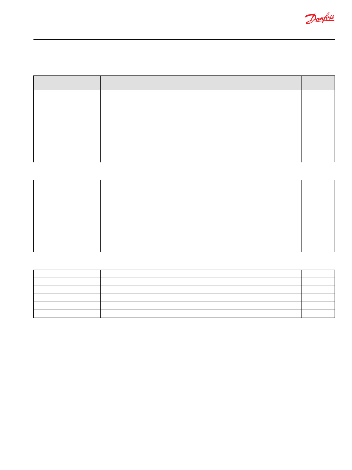
The date code is defined as the year and week of manufacture. The same item number may list more than
one part number. This indicates that there is more than one configuration for that item number. You will
see that there are different date codes for the different part numbers. Find the date code of your unit
from the nameplate to determine which service part number you need to order.
Example: The service part desired is item G30
Order Code Item Date Begin Date End Part Number Part Name Qty. per
80 G30 89-17 8000243 End cap gasket 1
G30 89-16 8000151 End cap gasket
(SB-1995-006)
Model/Kit
1
All units using this order code with a date code prior to 89-17 must use part number “8000151.” All units
with a date code of 89-17 and newer must use part number “8000243.”
A Service Bulletin Number (SB-_ _ _ _ - _ _ _) may follow the “Part Name” of the part you desire. You must
read that Service Bulletin prior to ordering that part. The information contained in these Service Bulletins,
as of the print date of this bulletin, are included at the end of this manual. Service Bulletins contain more
detailed information such as interchangeability, what additional parts are involved, etc. It is suggested
that you add additional Service Bulletins to this manual as you receive them.
Procedure to identify a part
The modular design of this product results in a simplified service parts list and part number identification
procedure.
The same item numbers are used for same part names on all units within a product type. A part number
that has another number following it in parentheses is done to make this a world wide manual.
Regional part numbers
Some part numbers are region specific and should be ordered accordingly.
As an example, the part number (example: 314583 (9008000-0118) will be used. The first number is sold
in Germany. The number in parentheses is sold in the United States. Customers would order
9008000-0118 if ordering the part in the United States.
Example of a part identification (H1B 250)
The nameplate on an H1 motor has an Order Code of H1B250 A L1 BA N A PA VS FS S B 50 NN 050 N 00
NNN. Use the following procedures to determine the part number of the minimum angle set screw used
on this motor
1. Referring to the minimum displacement module in the Order code on page 8, the minimum angle
set screw option for this motor is identified by the code“050”. (H1B250 A L1 BA N A PA VS FS S B 50
NN
050 N 00 NNN).
2. Referring to the Service Parts List, find the minimum displacement group. Next find the order code
that relates to this unit, which is “050”. The minimum angle set screw is found to be item N1000 and
part number 750646.
6 | © Danfoss | December 2021 AX152986482121en-000611
Page 7
Parts Manual
H1B 250 Bent Axis Motor
General information
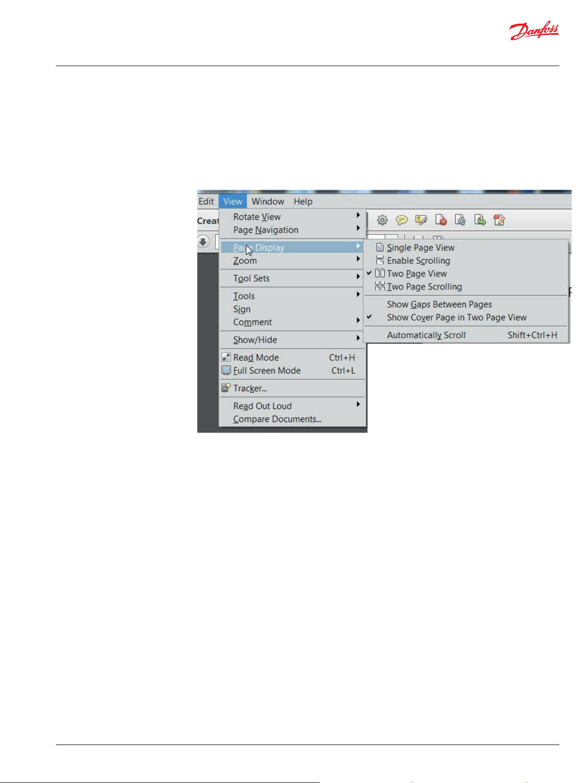
Adobe Acrobat 2-page viewing
While viewing manual in Adobe Acrobat, the following settings need to be applied to ensure proper
page display.
1. Select “View” → “Page Display” → “Two Page View”
2. Select “View” → “Page Display” → “Show Cover Page in Two Page View”
©
Danfoss | December 2021 AX152986482121en-000611 | 7
Page 8
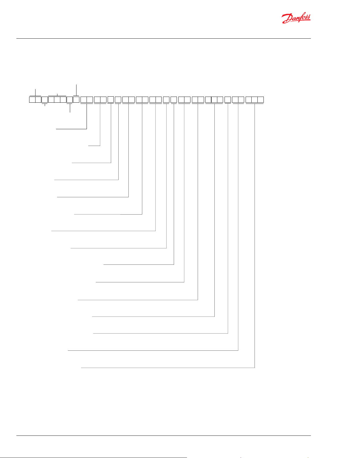
L
1
B
A
A
V S
A
P
N
F S
0
0 NB 5
S
0
0
Servo pressure supply
Not applicable
Orifice
Control
End cap
Flange/housing
Shaft
Speed sensor
Loop flushing shuttle system
B C
E
D
F G L5MH J
N N
0
K
NN N
Q R
P
N
Loop flushing relief valve
Special hardware
PCOR setting
Paint and Nametag
Minimum displacement
Maximum displacement
H1B
0
2
5
Series
Frame
Size
Product Type
A A
Product
Version
Port
Configuration
Parts Manual
H1B 250 Bent Axis Motor
General information
Order code
8 | © Danfoss | December 2021 AX152986482121en-000611
Page 9

Parts Manual
H1B 250 Bent Axis Motor
General information
Notes
©
Danfoss | December 2021 AX152986482121en-000611 | 9
Page 10
B0020
*B0035
B0050
B0040
B0010
B0025
B0028
B0027
B0029
B0061
B0060
B0180
B0050
B0190
B0010
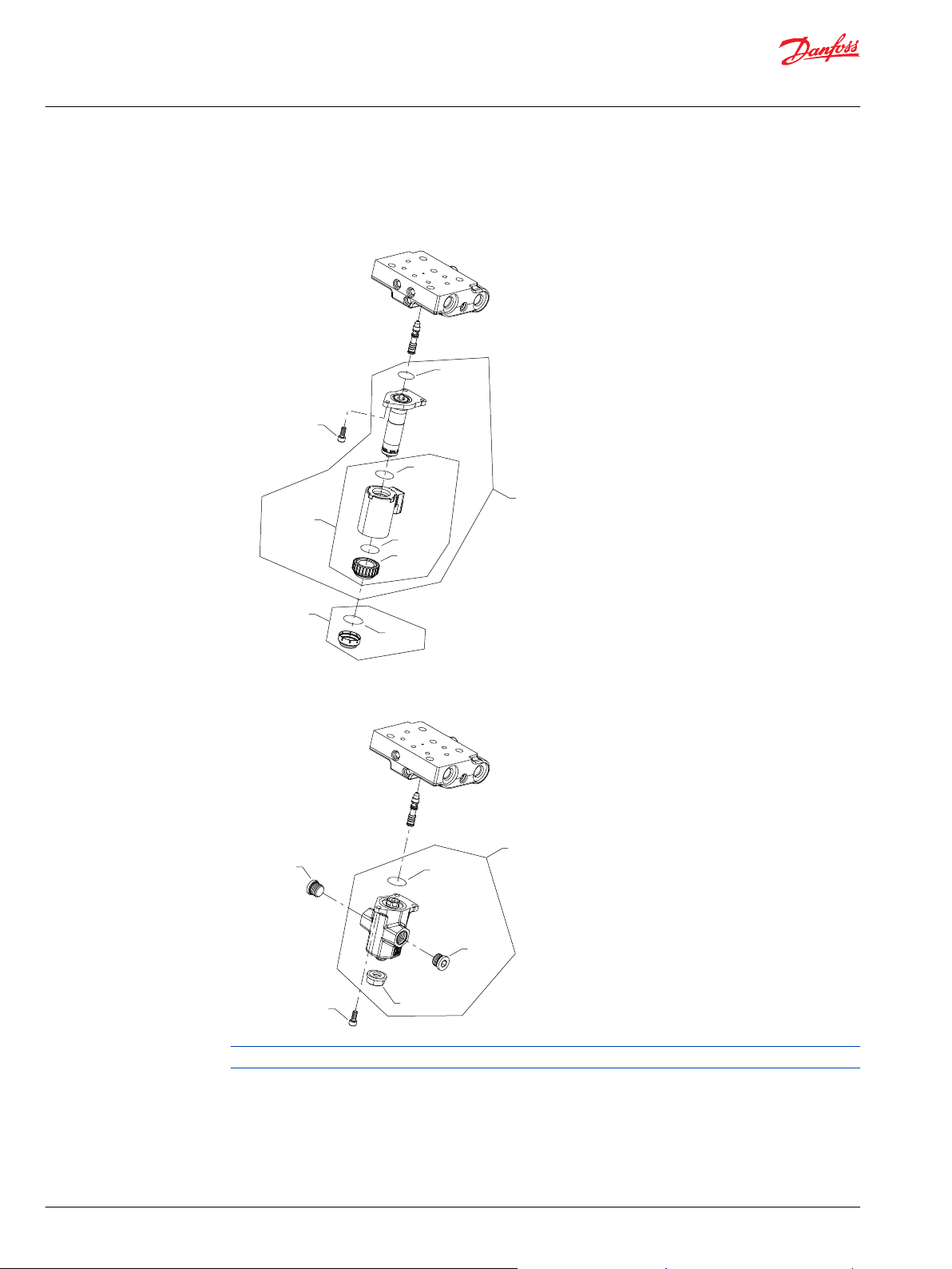
Parts Manual
H1B 250 Bent Axis Motor
Control
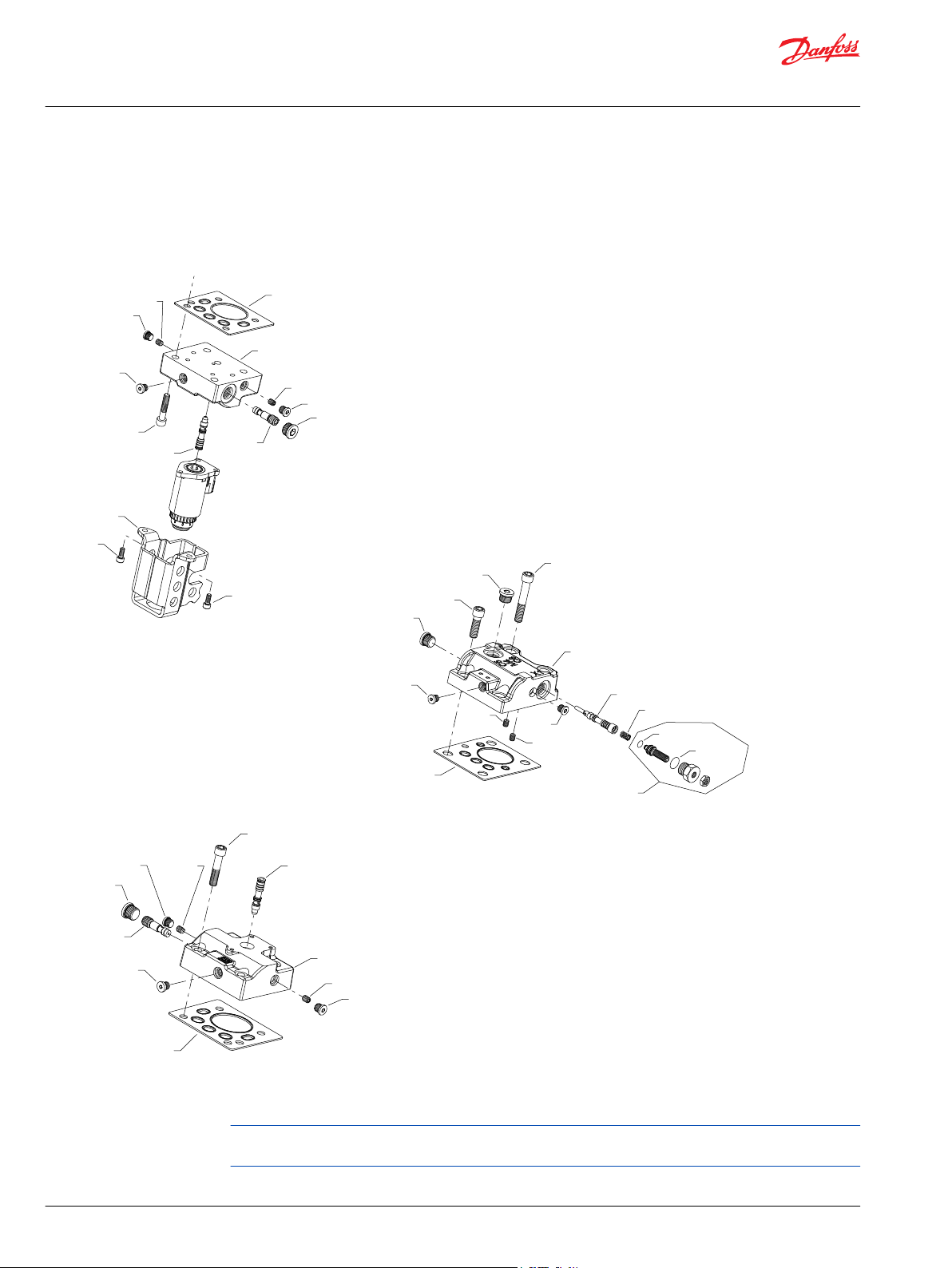
H1B control D1-DH
D1 and D2 configuration
DH configuration
Generic housings used to show part locations only.
* Included in overhaul seal kit Q210
10 | © Danfoss | December 2021 AX152986482121en-000611
Page 11

Parts Manual
H1B 250 Bent Axis Motor
Control
Electric proportional
Order code: D1
Item Date Begin Date End Part Number Part Name Qty. per
B0010 11-18 149053 Solenoid valve, proportional, 12 volt 1
B0020 11-18 11031746 Coil kit, 12 volt 1
B0025 11-18 11004735 O-ring 1
B0027 11-18 11004749 Coil nut 1
B0028 11-18 063172 O-ring 1
B0029 11-18 11037174 O-ring 1
B0035 11-18 11001952 O-ring 1
B0040 11-18 11014185 Plastic cap 1
B0050 11-18 716860 Screw, M5 x 12 3
Order code: D2
B0010 11-18 11002705 Solenoid valve, proportional, 24 volt 1
B0020 11-18 11031749 Coil kit, 24 volt 1
B0025 11-18 11004735 O-ring 1
B0027 11-18 11004749 Coil nut 1
B0028 11-18 063172 O-ring 1
B0029 11-18 11037174 O-ring 1
B0035 11-18 11001952 O-ring 1
B0040 11-18 11014185 Plastic cap 1
B0050 11-18 716860 Screw, M5 x 12 3
Model/Kit
Hydraulic proportional
Order code: DH
B0010 14-37 11146306 Actuator assembly 1
B0050 14-37 716860 Screw, M5 x 12 3
B0060 14-37 140644 Plug assembly 1
B0061 14-37 140644 Plug assembly 1
B0180 14-37 076042 (9003509-0012) Seal nut, M12 1
B0190 14-37 012575 (9004105-1170) O-ring 1
©
Danfoss | December 2021 AX152986482121en-000611 | 11
Page 12
*B0034
C2000
B0010
B0026
B0028
B0024
B0024
B0026
B0028
C2000
*B0034
B0010
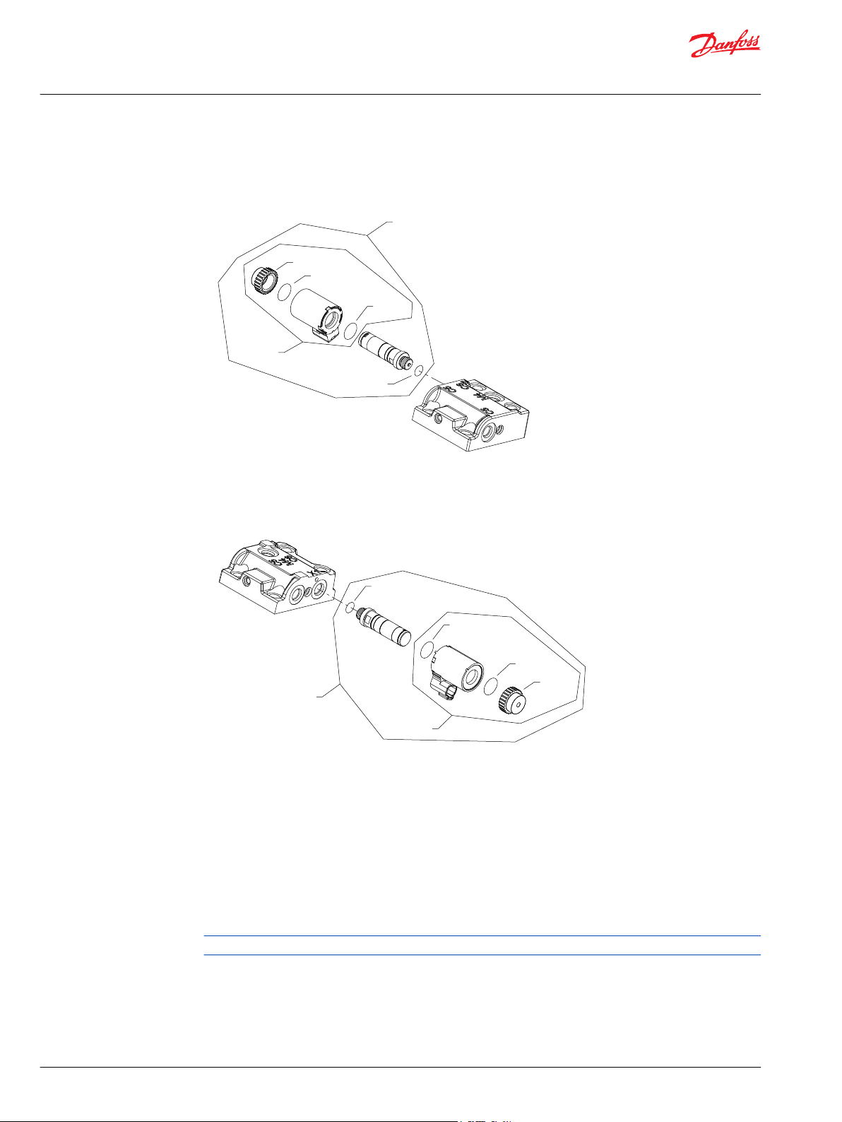
Parts Manual
H1B 250 Bent Axis Motor
Control
H1B control E1-F2
E1 and E2 configuration
F1 and F2 configuration
Generic housings used to show part location only.
* Included in overhaul seal kit Q210
12 | © Danfoss | December 2021 AX152986482121en-000611
Page 13
Parts Manual
H1B 250 Bent Axis Motor
Control
Electric 2-position
Order code: E1
Item Date Begin Date End Part Number Part Name Qty. per
B0010 11-18 11013615 Solenoid, on/off, 12 volt 1
B0024 11-18 11027046 O-ring 1
B0026 11-18 11027046 Coil nut 1
B0028 11-18 063172 O-ring
B0034 11-18 085043 (9004201-3700) O-ring 1
C2000 11-18 11031763 Coil kit, 12 volt 1
Order code: E2
B0010 11-18 11013616 Solenoid, on/off, 24 volt 1
B0024 11-18 11031608 O-ring 1
B0026 11-18 11027046 Coil nut 1
B0028 11-18 063172 O-ring 1
B0034 11-18 085043 (9004201-3700) O-ring 1
C2000 11-18 11031764 Coil kit, 24 volt 1
Model/Kit
Order code: F1
B0010 11-48 11013615 Solenoid, on/off, 12 volt 1
B0024 11-48 11027046 O-ring 1
B0026 11-48 11027046 Coil nut 1
B0028 11-48 063172 O-ring
B0034 11-48 085043 (9004201-3700) O-ring 1
C2000 11-48 11031763 Coil kit, 12 volt 1
Order code: F2
B0010 11-48 11013616 Solenoid, on/off, 24 volt 1
B0024 11-48 11031608 O-ring 1
B0026 11-48 11027046 Coil nut 1
B0028 11-48 063172 O-ring 1
B0034 11-48 085043 (9004201-3700) O-ring 1
C2000 11-48 11031764 Coil kit, 24 volt 1
Order code: HE and HF
No parts
©
Danfoss | December 2021 AX152986482121en-000611 | 13
Page 14

*B0035
B0040
B0010
B0020
B0050
B0025
B0028
B0027
B0029
B0190
B0180
B0050
B0060
B0061
B0010
Parts Manual
H1B 250 Bent Axis Motor
Control
H1B control K1-KH
K1, K2 configuration
KH configuration
Generic housing used to show part location only.
* Included in overhaul seal kit Q210
14 | © Danfoss | December 2021 AX152986482121en-000611
Page 15
Parts Manual
H1B 250 Bent Axis Motor
Control
Order code: K1
Item Date Begin Date End Part Number Part Name Qty. per
B0010 11-18 149053 Solenoid valve, proportional, 12 volt 1
B0020 11-18 11031746 Coil kit, 12 volt 1
B0025 11-18 11004735 O-ring 1
B0027 11-18 11004749 Coil nut 1
B0028 11-18 063172 O-ring 1
B0029 11-18 11037174 O-ring 1
B0035 11-18 11001952 O-ring 1
B0040 11-18 11014185 Plastic cap 1
B0050 11-18 716860 Screw, M5 x 12 3
Order code: K2
B0010 11-18 11002705 Solenoid valve, proportional, 24 volt 1
B0020 11-18 11031749 Coil kit, 24 volt 1
B0025 11-18 11004735 O-ring 1
B0027 11-18 11004749 Coil nut 1
B0028 11-18 063172 O-ring 1
B0029 11-18 11037174 O-ring 1
B0035 11-18 11001952 O-ring 1
B0040 11-18 11014185 Plastic cap 1
B0050 11-18 716860 Screw, M5 x 12 3
Model/Kit
Order code: KH
B0010 15-48 11146306 Actuator assembly 1
B0050 15-48 716860 Screw, M5 x 12 3
B0060 15-48 140644 Plug assembly 1
B0061 15-48 140644 Plug assembly 1
B0180 15-48 076042 (9003509-0012) Seal nut, M12 1
B0190 15-48 012575 (9004105-1170) O-ring 1
©
Danfoss | December 2021 AX152986482121en-000611 | 15
Page 16

B0020
*B0035
B0050
B0040
B0010
B0025
B0028
B0027
B0029
B0061
B0060
B0180
B0050
B0190
B0010
Parts Manual
H1B 250 Bent Axis Motor
Control
H1B control L1-LH
L1 and L2 configuration
LH configuration
Generic housings used to show part locations only.
* Included in overhaul seal kit Q210
16 | © Danfoss | December 2021 AX152986482121en-000611
Page 17
Parts Manual
H1B 250 Bent Axis Motor
Control
Electric proportional
Order code: L1
Item Date Begin Date End Part Number Part Name Qty. per
B0010 11-18 149053 Solenoid valve, proportional, 12 volt 1
B0020 11-18 11031746 Coil kit, 12 volt 1
B0025 11-18 11004735 O-ring 1
B0027 11-18 11004749 Coil nut 1
B0028 11-18 063172 O-ring 1
B0029 11-18 11037174 O-ring 1
B0035 11-18 11001952 O-ring 1
B0040 11-18 11014185 Plastic cap 1
B0050 11-18 716860 Screw, M5 x 12 3
Order code: L2
B0010 11-18 11002705 Solenoid valve, proportional, 24 volt 1
B0020 11-18 11031749 Coil kit, 24 volt 1
B0025 11-18 11004735 O-ring 1
B0027 11-18 11004749 Coil nut 1
B0028 11-18 063172 O-ring 1
B0029 11-18 11037174 O-ring 1
B0035 11-18 11001952 O-ring 1
B0040 11-18 11014185 Plastic cap 1
B0050 11-18 716860 Screw, M5 x 12 3
Model/Kit
Hydraulic proportional
Order code: LH
B0010 14-37 11146306 Actuator assembly 1
B0050 14-37 716860 Screw, M5 x 12 3
B0060 14-37 140644 Plug assembly 1
B0061 14-37 140644 Plug assembly 1
B0180 14-37 076042 (9003509-0012) Seal nut, M12 1
B0190 14-37 012575 (9004105-1170) O-ring 1
©
Danfoss | December 2021 AX152986482121en-000611 | 17
Page 18
*B0035
B0040
B0010
B0020
B0050
B0025
B0028
B0027
B0029
B0190
B0180
B0050
B0060
B0061
B0010
Parts Manual
H1B 250 Bent Axis Motor
Control
H1B control M1-MH
M1, M2 configuration
MH configuration
Generic housing used to show part location only.
* Included in overhaul seal kit Q210
18 | © Danfoss | December 2021 AX152986482121en-000611
Page 19
Parts Manual
H1B 250 Bent Axis Motor
Control
Order code: M1
Item Date Begin Date End Part Number Part Name Qty. per
B0010 11-18 149053 Solenoid valve, proportional, 12 volt 1
B0020 11-18 11031746 Coil kit, 12 volt 1
B0025 11-18 11004735 O-ring 1
B0027 11-18 11004749 Coil nut 1
B0028 11-18 063172 O-ring 1
B0029 11-18 11037174 O-ring 1
B0035 11-18 11001952 O-ring 1
B0040 11-18 11014185 Plastic cap 1
B0050 11-18 716860 Screw, M5 x 12 3
Order code: M2
B0010 11-18 11002705 Solenoid valve, proportional, 24 volt 1
B0020 11-18 11031749 Coil kit, 24 volt 1
B0025 11-18 11004735 O-ring 1
B0027 11-18 11004749 Coil nut 1
B0028 11-18 063172 O-ring 1
B0029 11-18 11037174 O-ring 1
B0035 11-18 11001952 O-ring 1
B0040 11-18 11014185 Plastic cap 1
B0050 11-18 716860 Screw, M5 x 12 3
Model/Kit
Order code: MH
B0010 14-23 11146306 Actuator assembly 1
B0050 14-23 716860 Screw, M5 x 12 3
B0060 14-23 140644 Plug assembly 1
B0061 14-23 140644 Plug assembly 1
B0180 14-23 076042 (9003509-0012) Seal nut, M12 1
B0190 14-23 012575 (9004105-1170) O-ring 1
Order code: N1, NA, NB
No parts
©
Danfoss | December 2021 AX152986482121en-000611 | 19
Page 20
*B0034
B0020
B0010
B0026
B0028
B0024
*B0034
C2000
B0010
B0026
B0028
B0024
Parts Manual
H1B 250 Bent Axis Motor
Control
H1B control P1-T2
P1 and P2 configuration
T1 and T2 configuration
Generic housings used to show part location only.
* Included in overhaul seal kit Q210
20 | © Danfoss | December 2021 AX152986482121en-000611
Page 21
Parts Manual
H1B 250 Bent Axis Motor
Control
Order code: P1
Item Date Begin Date End Part Number Part Name Qty. per
B0010 11-18 11013613 Solenoid valve, proportional, 12 volt 1
B0020 11-18 11031751 Coil kit, 12 volt 1
B0024 11-18 11031608 O-ring 1
B0026 11-18 11027046 Coil nut 1
B0028 11-18 063172 O-ring 1
B0034 11-18 085043 (9004201-3700) O-ring 1
Order code: P2
B0010 11-18 11013614 Solenoid valve, proportional, 24 volt 1
B0020 11-18 11031762 Coil kit, 24 volt 1
B0024 11-18 11031608 O-ring 1
B0026 11-18 11027046 Coil nut 1
B0028 11-18 063172 O-ring 1
B0034 11-18 085043 (9004201-3700) O-ring 1
Model/Kit
Order code: T1
B0010 11-18 11013615 Solenoid, on/off, 12 volt 1
B0024 11-18 11031608 O-ring 1
B0026 11-18 11027046 Coil nut 1
B0028 11-18 063172 O-ring 1
B0034 11-18 085043 (9004201-3700) O-ring 1
C2000 11-18 11031763 Coil kit, 12 volt 1
Order code: T2
B0010 11-18 11013616 Solenoid, on/off, 24 volt 1
B0024 11-18 11031608 O-ring 1
B0026 11-18 11027046 Coil nut 1
B0028 11-18 063172 O-ring 1
B0034 11-18 085043 (9004201-3700) O-ring 1
C2000 11-18 11031764 Coil kit, 24 volt 1
©
Danfoss | December 2021 AX152986482121en-000611 | 21
Page 22
B0060
B0320
B0330
QB300
B0300
Parts Manual
H1B 250 Bent Axis Motor
Control
H1B control TA, TH
TA configuration
TH configuration
Generic housings used to show part location only.
* Included in overhaul seal kit Q210
22 | © Danfoss | December 2021 AX152986482121en-000611
Page 23
Parts Manual
H1B 250 Bent Axis Motor
Control
Order code: TA
Item Date Begin Date Begin Part Number Part Name Qty. per
B0060 11-46 140644 Plug assembly 1
Order code: TH
B0300 15-27 11157844 PCOR override adapter assembly 1
B0320 15-27 11157843 Sensing spool 1
B0330 15-27 11164139 O-ring 1
QB300 15-27 085043 (9004201-3700) O-ring 1
Model/Kit
©
Danfoss | December 2021 AX152986482121en-000611 | 23
Page 24
*C0130
C0025
C0060
C0080
C0075
C0010
C0060
(removed 11-21)
C0060
C0050
E00T2
E00T3
C0050
C0110
C0120
C0010
C0060
C0050
C0080
C0070
C0060
C0050
*C0130
E00T2
E00T3
C0110
C0120
C0090
*M223
*M224
Parts Manual
H1B 250 Bent Axis Motor
Servo pressure supply
H1B servo pressure AA, AD
AA configuration
AD configuration
* Included in overhaul seal kit Q210
24 | © Danfoss | December 2021 AX152986482121en-000611
Page 25
Parts Manual
H1B 250 Bent Axis Motor
Servo pressure supply
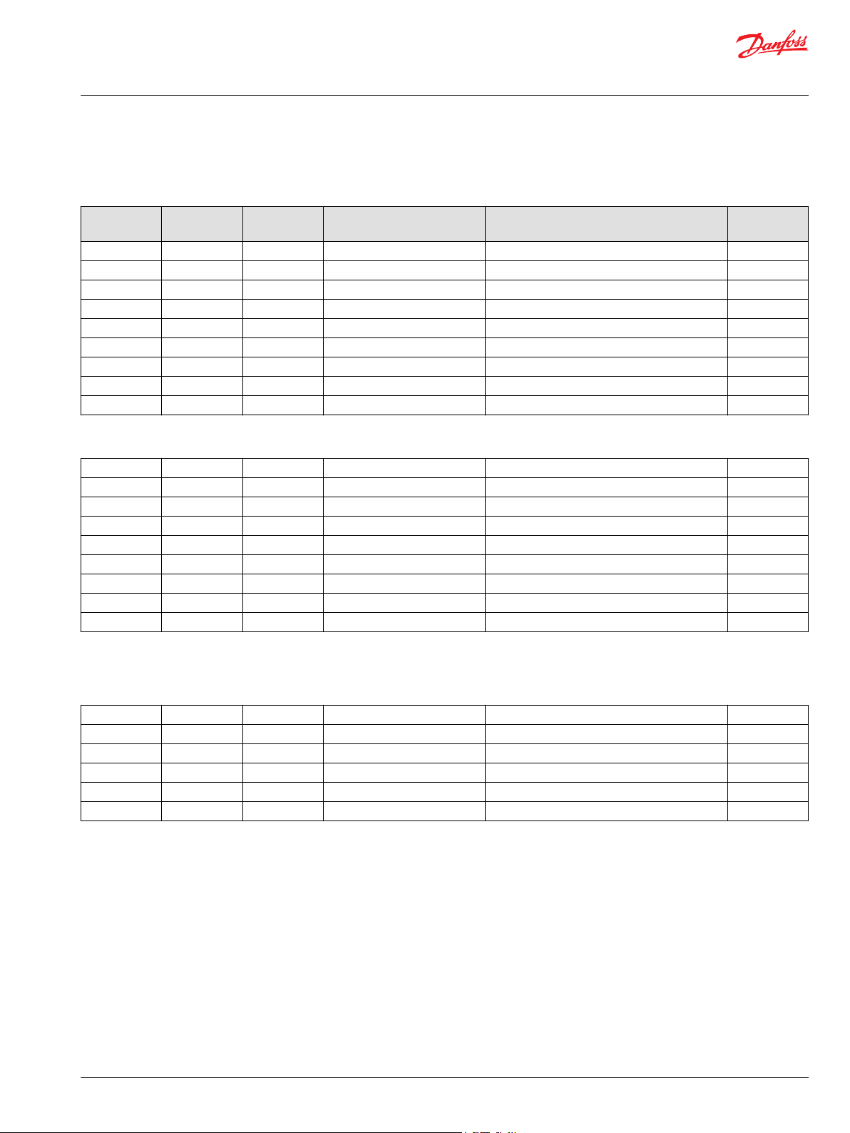
Order code: AA
Item Date Begin Date End Part Number Part Name Qty. per
C0010 11-18 11086113 Control housing, 2-position (SAE) 1
C0025 11-18 11000893 Shuttle valve assembly 1
C0050 11-18 140644 Plug assembly (SAE) 2
C0060 11-22 11040532 Plug assembly 2
C0060 11-18 11-21 11040532 Plug assembly 3
C0075 11-18 11016166 Spool 1
C0080 11-18 1160236 Spring (SAE) 1
C0110 11-18 737866 (9007314-1207) Screw, M12 x 30 2
C0120 11-18 283325 (9007314-1211) Screw, M12 x 50 2
C0130 11-18 11016168 Control seal 1
Order code: AD
C0010 12-14 11110070 Control housing, 2-position 1
C0050 12-14 140644 Plug assembly (SAE) 2
C0060 11-22
C0060 11-22 11040532 Plug assembly 2
C0070 12-14 11016228 Spool 1
C0080 12-14 11160236 Spring (SAE) 1
C0090 12-14 509360 Adjuster 1
C0110 12-14 737866 (9007314-1207) Screw, M12 x 30 2
C0120 12-14 283325 (9007314-1211) Screw, M12 x 50 2
C0130 12-14 11016168 Control seal 1
M223 12-14 085043 (9004201-3700) O-ring 1
M224 12-14 732479 O-ring 1
Model/Kit
©
Danfoss | December 2021 AX152986482121en-000611 | 25
Page 26
C0100
C0060
C0060
E00T2
C0060
E00T3
C0025
C0050
*C0130
C0110
C0010
C0100
C0060
C0060
E00T2
C0060
E00T3
C0025
C0050
*C0130
C0110
C0010
C0320
C0300
C0320
Parts Manual
H1B 250 Bent Axis Motor
Servo pressure supply
H1B servo pressure BA, BB
BA configuration
BB configuration
26 | © Danfoss | December 2021 AX152986482121en-000611
* Included in overhaul seal kit Q210
Page 27
Parts Manual
H1B 250 Bent Axis Motor
Servo pressure supply
Option BA and BB are available in SAE and metric. Please order accordingly.
Order code: BA
Item Date Begin Date End Part Number Part Name Qty. per
C0010 11-18 149057 Control housing, proportional (SAE) 1
C0010 15-45 11161819 Control housing, proportional (metric) 1
C0025 11-18 11000893 Shuttle valve assembly 1
C0050 11-18 140644 Plug assembly (SAE) 1
C0050 15-45 11178808 Plug assembly (metric) 1
C0060 11-18 11040532 Plug assembly 3
C0100 11-18 11146871 Spool (SAE) 1
C0100 15-45 11146871 Spool (metric) 1
C0110 11-18 710855 Screw, M8 x 35 4
C0130 11-18 149040 Control seal 1
Order code: BB
C0010 12-24 11116918 Control housing, proportional (SAE) 1
C0010 16-49 11169197 Control housing, proportional (metric) 1
C0025 12-24 11000893 Shuttle valve assembly 1
C0050 12-24 140644 Plug assembly (SAE) 1
C0050 16-49 11178808 Plug assembly (metric) 1
C0060 12-24 11040532 Plug assembly 3
C0100 12-24 11146871 Spool (SAE) 1
C0110 12-24 710855 Screw, M8 x 35 4
C0130 12-24 149040 Control seal 1
C0300 12-24 11086158 Protective cover 1
C0320 12-24 395822 Screw, M6 x 12mm 2
Model/Kit
©
Danfoss | December 2021 AX152986482121en-000611 | 27
Page 28
E00T2
E00T3
C0100
C0060
C0060
C0060
C0025
C0050
*C0130
C0110
C0010
C0320
C0300
C0320
C0010
C0060
C0050
C0080
C0070
C0060
C0050
*C0130
E00T2
E00T3
C0110
C0120
C0090
*M223
*M224
E00T3
E00T2
C0100
C0010
C0025
*C0130
C0060
C0050
C0060
C0060
C0110
(BC)
(BD)
(CA)
Parts Manual
H1B 250 Bent Axis Motor
Servo pressure supply
H1B servo pressure BC, BD, CA
Parts configuration
* Included in overhaul seal kit Q210
Option BC is only available in metric configuration. Option CA is available is both SAE and metric
configurations. Please order accordingly.
28 | © Danfoss | December 2021 AX152986482121en-000611
Page 29
Parts Manual
H1B 250 Bent Axis Motor
Servo pressure supply
Order code: BC
Item Date Begin Date End Part Number Part Name Qty. per
C0010 16-38 11169197 Control housing, proportional (metric) 1
C0025 16-38 11000893 Shuttle valve assembly 1
C0050 16-38 11178808 Plug assembly (metric) 1
C0060 16-38 11040532 Plug assembly 3
C0100 16-38 11146871 Spool (metric) 1
C0110 16-38 710855 Screw, M8 x 35 4
C0130 16-38 149040 Control seal 1
C0300 16-38 11086158 Protection cover 1
C0320 16-38 395822 Screw, M6 x 12 2
Order code: BD
C0010 12-14 11110071 Control housing, 2-position 1
C0050 12-14 140644 Plug assembly (SAE) 2
C0060 12-14 11040532 Plug assembly 2
C0070 12-14 11016228 Spool 1
C0080 12-14 11160236 Spring (SAE) 1
C0090 12-14 509360 Adjuster 1
C0110 12-14 737866 (9007314-1207) Screw, M12 x 30 2
C0120 12-14 283325 (9007314-1211) Screw, M12 x 50 2
C0130 12-14 11016168 Control seal 1
M223 12-14 085043 (9004201-3700) O-ring 1
M224 12-14 732479 O-ring 1
Model/Kit
Order code: CA
C0010 11-18 149057 Control housing, proportional (SAE) 1
C0010 11161819 Control housing, proportional (metric) 1
C0025 11-18 11000893 Shuttle valve assembly 1
C0050 11-18 140644 Plug assembly (SAE) 1
C0050 16-35 11178808 Plug assembly (metric) 1
C0060 11-18 11040532 Plug assembly 3
C0100 11-18 11146871 Spool (SAE) 1
C0100 16-35 11146871 Spool (metric) 1
C0110 11-18 710855 Screw, M8 x 35 4
C0130 11-18 149040 Control seal 1
©
Danfoss | December 2021 AX152986482121en-000611 | 29
Page 30
C0030
C0020
C0060
C0010
C0060
*B0034
C2000
C0040
B0026
B0028
B0024
C0060
C0050
*C0130
E00T2
E00T3
C0050
C0110
C0120
C0080
C0070
C0090
*M223
*M224
C0060
(removed 11-21)
Parts Manual
H1B 250 Bent Axis Motor
Servo pressure supply
H1B servo pressure D1, D2
D1 and D2 configuration
* Included in overhaul seal kit Q210
30 | © Danfoss | December 2021 AX152986482121en-000611
Page 31

Parts Manual
H1B 250 Bent Axis Motor
Servo pressure supply
Order code: D1 and D2 common parts
Item Date Begin Date End Part Number Part Name Qty. per
B0024 11-18 11031608 O-ring 1
B0026 11-18 11027046 Coil nut 1
B0028 11-18 063172 O-ring 1
B0034 11-18 085043 (9004201-3700) O-ring 1
C0010 11-18 11086114 Control housing, PCOR 1
C0020 11-18 11016229 Spool 1
C0030 11-18 11160236 Spring 1
C0050 11-18 140644 Plug assembly (SAE) 2
C0060 11-22 11040532 Plug assembly 3
C0060 11-18 11-21 11040532 Plug assembly 4
C0070 11-18 11016228 Spool 1
C0080 11-18 11160236 Spring 1
C0090 11-18 509360 Adjuster 1
C0110 11-18 737866 (9007314-1207) Screw, M12 x 30 2
C0120 11-18 283325 (9007314-1211) Screw, M12 x 50 2
C0130 11-18 11016168 Control seal 1
M223 11-18 085043 (9004201-3700) O-ring 1
M224 11-18 732479 O-ring 1
Model/Kit
Order code: D1
C0040 11-18 11013615 Solenoid, on/off, 12 volt 1
C2000 11-18 11031763 Coil kit, 12 volt 1
Order code: D2
C0040 11-18 11013616 Solenoid, on/off, 24 volt 1
C2000 11-18 11031764 Coil kit, 24 volt 1
©
Danfoss | December 2021 AX152986482121en-000611 | 31
Page 32

C0025
C0010
C0060
C0060
(removed 11-21)
C0060
C0050
*C0130
E00T2
E00T3
C0080
C0070
C0090
*M223
*M224
C0050
C0110
C0120
C0010
C0060
C0050
C0080
C0075
C0110
C0120
C0050
C0025
C0060
*C0130
E00T2
E00T3
Parts Manual
H1B 250 Bent Axis Motor
Servo pressure supply
H1B servo pressure DA, EA
DA configuration
EA configuration
* Included in overhaul seal kit Q210
32 | © Danfoss | December 2021 AX152986482121en-000611
Page 33

Parts Manual
H1B 250 Bent Axis Motor
Servo pressure supply
Order code: DA
Item Date Begin Date End Part Number Part Name Qty. per
C0010 11-18 11086115 Control housing, PCOR 1
C0025 11-18 11000893 Shuttle valve assembly 1
C0050 11-18 140644 Plug assembly (SAE) 2
C0060 11-22 11040532 Plug assembly 2
C0060 11-18 11-21 11040532 Plug assembly 3
C0070 11-18 11016228 Spool 1
C0080 11-18 11160236 Spring 1
C0090 11-18 509360 Adjuster 1
M223 11-18 085043 (9004201-3700) O-ring 1
M224 11-18 732479 O-ring 1
Order code: EA
C0010 11-22 11099281 Control housing, 2-position 1
C0025 11-22 11000893 Shuttle valve assembly 1
C0050 11-22 140644 Plug assembly 1
C0060 11-22 11040532 Plug assembly 2
C0075 11-22 11122114 Spool, 2-position 1
C0080 11-22 11160236 Spring 1
C0110 11-22 737866 (9007314-1207) Screw, M12 x 30 2
C0120 11-22 283325 (9007314-1211) Screw, M12 x 50 2
C0130 11-22 11016168 Control seal 1
Model/Kit
©
Danfoss | December 2021 AX152986482121en-000611 | 33
Page 34

C0060
E00T2
E00T3
C0010
C0060
C0080
C0070
*M223
*M224
C0050
C0110
C0120
C0030
C0020
C0050
*C0130
B0024
B0026
B0028
C2000
*B0034
C0040
C0090
Parts Manual
H1B 250 Bent Axis Motor
Servo pressure supply
H1B servo pressure G1, G2
G1 and G2 configuration
* Included in overhaul seal kit Q210
34 | © Danfoss | December 2021 AX152986482121en-000611
Page 35

Parts Manual
H1B 250 Bent Axis Motor
Servo pressure supply
Order code: G1 and G2 common parts
Item Date Begin Date End Part Number Part Name Qty. per
B0024 16-07 11031608 O-ring 1
B0026 16-07 11027046 Coil nut 1
B0028 16-07 063172 O-ring 1
B0034 16-07 085043 (9004201-3700) O-ring 1
C0010 16-07 11173253 Control housing, 2-position 1
C0020 16-07 11016229 Spool 1
C0030 16-07 11160236 Spring 1
C0050 16-07 140644 Plug assembly (SAE) 2
C0060 16-07 11040532 Plug assembly 3
C0070 16-07 11016228 Spool 1
C0080 16-07 11160236 Spring 1
C0090 16-07 509360 Adjuster 1
C0110 16-07 737866 (9007314-1207) Screw, M12 x 30 2
C0120 16-07 283325 (9007314-1211) Screw, M12 x 50 2
C0130 16-07 11016168 Control seal 1
M223 16-07 085043 (9004201-3700) O-ring 1
M224 16-07 732479 O-ring 1
Model/Kit
Order code: G1
C0040 16-07 11013615 Solenoid valve, 12v 1
C200 16-07 11031763 Coil kit, 12 volt 1
Order code: G2
C0040 16-07 11013616 Solenoid valve, 24v 1
C2000 16-07 11031764 Coil kit, 24 volt 1
©
Danfoss | December 2021 AX152986482121en-000611 | 35
Page 36

*C0130
C0060
E00T2
E00T3
C0050
C0010
C0060
C0050
C0025
C0110
C0120
C0080
C0070
C0090
*M223
*M224
*C0130
C0060
E00T2
E00T3
C0010
C0060
C0020
C1400
C1400
C0080
C0070
C0090
*M223
*M224
C0050
C0110
C0120
*C0130
C0060
E00T2
E00T3
C0010
C0060
C0080
C0070
C0090
*M223
*M224
C0050
C0110
C0120
Parts Manual
H1B 250 Bent Axis Motor
Servo pressure supply
H1B servo pressure HA-HD
HA configuration
HB and HD configuration
HC configuration
* Included in overhaul seal kit Q210
36 | © Danfoss | December 2021 AX152986482121en-000611
Page 37

Parts Manual
H1B 250 Bent Axis Motor
Servo pressure supply
Order code: Common parts
Item Date Begin Date End Part Number Part Name Qty. per
C0070 15-37 11016228 Spool 1
C0080 15-37 11160236 Spring 1
C0090 15-37 509360 Adjuster 1
C0110 15-37 737866 (9007314-1207) Screw, M12 x 30 2
C0120 15-37 283325 (9007314-1211) Screw, M12 x 50 2
C0130 15-37 11016168 Control seal 1
M223 15-37 085043 (9004201-3700) O-ring 1
M224 15-37 732479 O-ring 1
Order code: HA
C0010 15-37 11162117 Control housing, 2-position 1
C0025 15-37 11000893 Shuttle valve assembly 1
C0050 15-37 140644 Plug assembly 2
C0060 15-37 11040532 Plug assembly 2
Model/Kit
Order code: HB
C0010 15-37 11162118 Control housing, 2-position 1
C0020 15-37 11162120 Spool 1
C0050 15-37 140644 Plug assembly 1
C0060 15-37 11040532 Plug assembly 3
Order code: HC
C0010 15-37 11162119 Control housing, 2-position 1
C0050 15-37 140644 Plug assembly 1
C0060 15-37 11040532 Plug assembly 2
Order code: HD
C0010 20-48 11272360 Control housing, 2-position 1
C0020 20-48 11162120 Spool 1
C0050 20-48 140644 Plug assembly 1
C0060 20-48 11040532 Plug assembly 3
C1400 20-48 11151817 Limiter plug 2
©
Danfoss | December 2021 AX152986482121en-000611 | 37
Page 38

E00T3
E00T2
C0010
C0050
C0140
C0050C0050
C0025
C0080
C0060
C0150
C0060
*C0130
C0110
C0120
C0160
*QC160
C0060
C0050
C0140
C0080
C0060
C0150
C0060
C0010
C0025
C0060
C0050
*C0130
E00T3
C0110
C0120
C0160
QC160
E00T2
(HE)
(HF)
Parts Manual
H1B 250 Bent Axis Motor
Servo pressure supply
H1B servo pressure HE, HF
HE and HF configuration
* Included in overhaul seal kit Q210
Option HE is available in SAE and metric. Please order accordingly.
38 | © Danfoss | December 2021 AX152986482121en-000611
Page 39

Parts Manual
H1B 250 Bent Axis Motor
Servo pressure supply
Order code: HE and HF common parts
Item Date Begin Date End Part Number Part Name Qty. per
C0025 11-18 11000893 Shuttle valve assembly 1
C0060 11-18 11040532 Plug assembly 3
C0110 11-18 737866 (9007314-1207) Screw, M12 x 30 2
C0120 11-18 283325 (9007314-1211) Screw, M12 x 50 2
C0130 11-18 11016168 Control seal 1
C0150 11-18 11068172 Spool 1
C0160 11-18 511244 Plug assembly 1
QC160 11-18 039297 (9004201-1200) O-ring 1
Order code: HE
C0010 11-18 11086117 Control housing, 2-position (SAE) 1
C0010 11-18 11175039 Control housing, 2-position (metric) 1
C0050 11-18 140644 Plug assembly (SAE) 2
C0050 11-18 11178808 Plug assembly (metric) 2
C0080 11-18 11160236 Spring (SAE) 1
C0080 11-18 11160236 Spring (metric) 1
C0140 11-18 9005110-8700 (315325) Plug assembly (SAE) 1
C0140 11-18 9005110-8700 (315325) Plug assembly (metric) 1
Model/Kit
Order code: HF
C0010 11-18 11086118 Control housing, 2-position (SAE) 1
C0050 11-18 140644 Plug assembly (SAE) 2
C0080 11-18 11160236 Spring (SAE) 1
C0140 11-18 9005110-8700 (315325) Plug assembly (SAE) 1
©
Danfoss | December 2021 AX152986482121en-000611 | 39
Page 40

C0120
C0110
C0010
C0100
C0060
C0060
*B0034
C2000
C0040
B0026
B0028
B0024
C0050
C0060
C0030
C0020
C0050
*C0130
C0060
E00T2
C0060
E00T3
C0080
C0070
*M223
*M224
C0090
Parts Manual
H1B 250 Bent Axis Motor
Servo pressure supply
H1B servo pressure K1, K2
K1 and K2 configuration
* Included in overhaul seal kit Q210
40 | © Danfoss | December 2021 AX152986482121en-000611
Page 41

Parts Manual
H1B 250 Bent Axis Motor
Servo pressure supply
Order code: K1 and K2 common parts
Item Date Begin Date End Part Number Part Name Qty. per
B0024 11-18 11031608 O-ring 1
B0026 11-18 11027046 Coil nut 1
B0028 11-18 063172 O-ring 1
B0034 11-18 085043 O-ring 1
C0010 11-18 11026748 Control housing, proportional, PCOR 1
C0020 11-18 11026792 Spool 1
C0030 11-18 11160236 Spring 1
C0050 11-18 140644 Plug assembly SAE 2
C0060 11-18 11040532 Plug assembly 9
C0070 11-18 11026751 Spool 1
C0080 11-18 11160236 Spring 1
C0090 11-18 509360 Adjuster 1
C0100 11-18 11146871 Spool 1
C0110 11-18 710855 Screw, M8 x 35 2
C0120 11-18 746644 (9007314-0810) Screw, M8 x 45 2
C0130 11-18 149040 Control seal 1
M223 11-18 085043 (9004201-3700) O-ring 1
M224 11-18 732479 O-ring 1
Model/Kit
Order code: K1
C0040 11-18 11013615 Solenoid, on/off, 12 volt 1
C2000 11-18 11031763 Coil kit, 12 volt 1
Order code: K2
C0040 11-18 11013616 Solenoid, on/off, 24 volt 1
C2000 11-18 11031764 Coil kit, 24 volt 1
©
Danfoss | December 2021 AX152986482121en-000611 | 41
Page 42

E101 604E
C0110
C0100
C0060
C0060
*C0130
C0050
C0060
C0025
C0060
C0050
C0010
C0060
E00T2
C0060
E00T3
C0080
C0070
*M223
*M224
C0090
C0120
C0120
C0110
C0010
C0100
C0060
C0060
C0050
C0060
*C0130
C0060
E00T2
C0060
E00T3
C0080
C0070
*M223
*M224
C0090
C1400
C0020
C1400
Parts Manual
H1B 250 Bent Axis Motor
Servo pressure supply
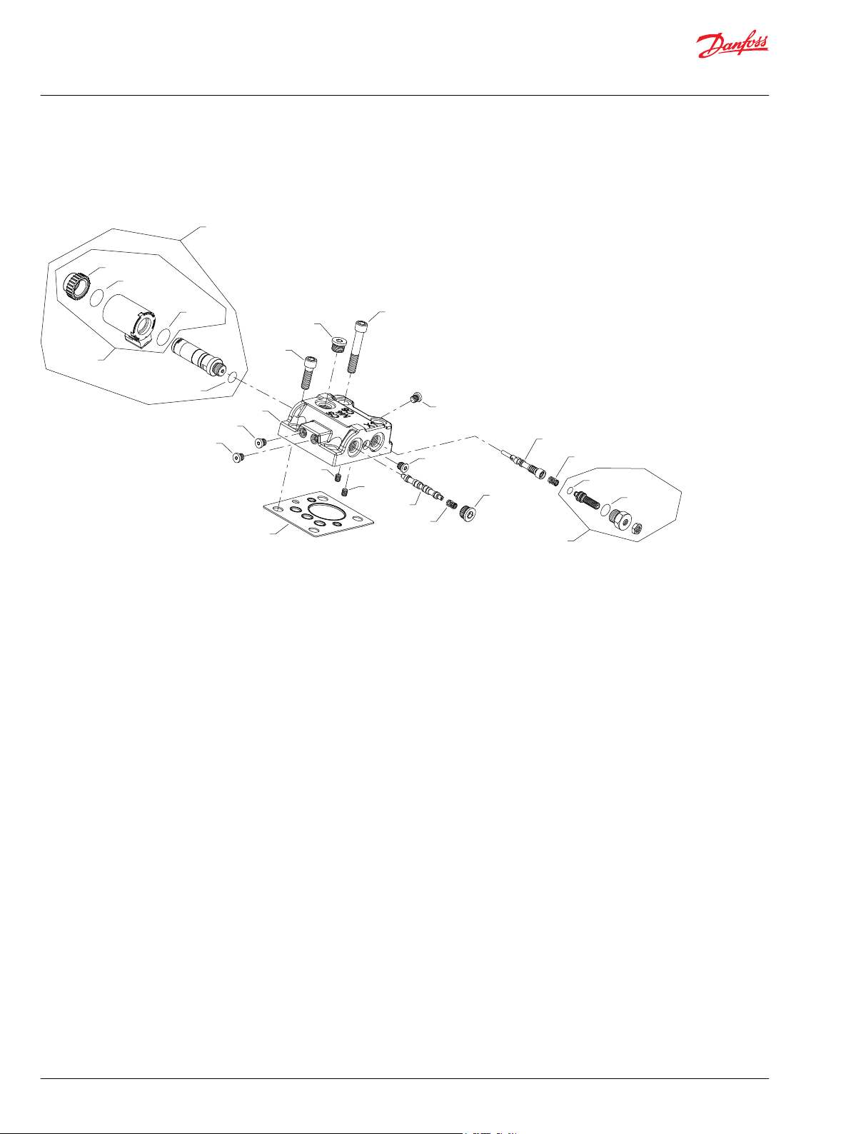
H1B servo pressure KA, KH
KA configuration
KH configuration
* Included in overhaul seal kit Q210
42 | © Danfoss | December 2021 AX152986482121en-000611
Page 43

Parts Manual
H1B 250 Bent Axis Motor
Servo pressure supply
Order code: KA
Item Date Begin Part Number Part Name Qty. per
C0010 11-18 11026749 Control housing, proportional, PCOR 1
C0025 11-18 11000893 Shuttle valve assembly 1
C0050 11-18 140644 Plug assembly (SAE) 1
C0060 11-18 11040532 Plug assembly 8
C0070 11-18 11026751 Spool 1
C0080 11-18 11160236 Spring 1
C0090 11-18 509360 Adjuster 1
C100 11-18 11146871 Spool 1
C0110 11-18 710855 Screw, M8 x 35 2
C0120 11-18 746644 (9007314-0810) Screw, M8 x 45 2
C0130 11-18 149040 Control seal 1
M223 11-18 085043 (9004201-3700) O-ring 1
M224 11-18 732479 O-ring 1
Model/Kit
Order code: KH
C0010 15-48 11161283 Control housing, proportional, PCOR 1
C0020 15-48 11151818 Spool 1
C0050 15-48 140644 Plug assembly 1
C0060 15-48 11040532 Plug assembly 9
C0070 15-48 11026751 Spool 1
C0080 15-48 11160236 Spring 1
C0090 15-48 509360 Adjuster 1
C100 15-48 11146871 Spool 1
C0110 15-48 710855 Screw, M8 x 35 2
C0120 15-48 746644 (9007314-0810) Screw, M8 x 45 2
C0130 15-48 149040 Control seal 1
C1400 15-48 11151817 Limiter plug 2
M223 15-48 085043 (9004201-3700) O-ring 1
M224 15-48 732479 O-ring 1
©
Danfoss | December 2021 AX152986482121en-000611 | 43
Page 44

C0100
C0060
C0060
E00T3
C0060
E00T2
C0050
*C0130
C0110
C0010
*B0034
C2000
C0070
B0026
B0028
B0024
C0120
C0040
C0080
C0050
C0020
C0030
C0060
C0060
C0090
*M223
*M224
Parts Manual
H1B 250 Bent Axis Motor
Servo pressure supply
H1B servo pressure M1, M2
M1 and M2 configuration
* Included in overhaul seal kit Q210
44 | © Danfoss | December 2021 AX152986482121en-000611
Page 45

Parts Manual
H1B 250 Bent Axis Motor
Servo pressure supply
Order code: M1 and M2 common parts
Item Date Begin Date End Part Number Part Name Qty. per
B0024 11-18 11031608 O-ring 1
B0026 11-18 11027046 Coil nut 1
B0028 11-18 063172 O-ring 1
B0034 11-18 085043 (9004201-3700) O-ring 1
C0010 11-18 11028958 Control housing, proportional, PCOR 1
C0020 11-18 11026792 Spool 1
C0030 11-18 11160236 Spring 1
C0050 11-18 140644 Plug assembly (SAE) 2
C0060 11-18 11040532 Plug assembly 9
C0070 11-18 11028957 Spool 1
C0080 11-18 11160236 Spring 1
C0090 11-18 509360 Adjuster 1
C0100 11-18 11146871 Spool 1
C0110 11-18 710855 Screw, M8 x 35 2
C0120 11-18 746644 (9007314-0810) Screw, M8 x 45 2
C0130 11-18 149040 Control seal 1
M223 11-18 085043 (9004201-3700) O-ring 1
M224 11-18 732479 O-ring 1
Model/Kit
Order code: M1
C0040 11-18 11013615 Solenoid, on/off, 12 volt 1
C2000 11-18 11031763 Coil kit, 12 volt 1
Order code: M2
C0040 11-18 11013616 Solenoid, on/off, 24 volt 1
C2000 11-18 11031764 Coil kit, 24 volt 1
©
Danfoss | December 2021 AX152986482121en-000611 | 45
Page 46

C0100
C0060
C0060
E00T3
C0060
E00T2
C0050
*C0130
C0110
C0010
C0070
C0110
C0080
C0050
C0060
C0060
C0025
C0090
*M223
*M224
C0060
C0100
C0060
C0060
E00T3
C0060
E00T2
C0050
*C0130
C0110
C0010
C0070
*B0034
B0020
B0026
B0028
B0024
C0040
C0080
C0050
C0020
C0030
C0060
C0060
C0320
C0300
C0320
C0120
C0320
C0310
C0320
C0090
*M223
*M224
Parts Manual
H1B 250 Bent Axis Motor
Servo pressure supply
H1B servo pressure MA, MF
MA configuration
MF configuration
* Included in overhaul seal kit Q210
46 | © Danfoss | December 2021 AX152986482121en-000611
Page 47

Parts Manual
H1B 250 Bent Axis Motor
Servo pressure supply
Order code: MA
Item Date Begin Date End Part Number Part Name Qty. per
C0010 11-18 11028959 Control housing, proportional, PCOR 1
C0025 11-18 11000893 Shuttle valve assembly 1
C0050 11-18 140644 Plug assembly (SAE) 2
C0060 11-18 11040532 Plug assembly 8
C0070 11-18 11028957 Spool 1
C0080 11-18 11160236 Spring 1
C0090 11-18 509360 Adjuster 1
C0100 11-18 11146871 Spool 1
C0110 11-18 710855 Screw, M8 x 35 2
C0120 11-18 746644 (9007314-0810) Screw, M8 x 45 2
C0130 11-18 149040 Control seal 1
M223 11-18 085043 (9004201-3700) O-ring 1
M224 11-18 732479 O-ring 1
Model/Kit
Order code: MF
B0020 12-05 11031763 Coil kit, 12 volt 1
B0024 12-05 11031608 O-ring 1
B0026 12-05 11027046 Coil nut 1
B0028 12-05 063172 O-ring 1
B0034 12-05 085043 (9004201-3700) O-ring 1
C0010 12-05 11123556 Control housing, proportional, PCOR 1
C0020 12-05 11101616 Spool 1
C0030 12-05 11160236 Spring 1
C0040 12-05 11013615 Solenoid, on/off, 12 volt 1
C0050 12-05 140644 Plug assembly 2
C0060 12-05 11040532 Plug assembly 9
C0070 12-05 11028957 Spool 1
C0080 12-05 11160263 Spring 1
C0090 12-05 509360 Adjuster 1
C0100 12-05 11146871 Spool 1
C0110 12-05 710855 Screw, M8 x 35 2
C0120 12-05 746644 (9007314-0810) Screw, M8 x 45 2
C0130 12-05 149040 Control seal 1
C0300 12-05 11086158 Protective cover 1
C0310 12-05 11086159 Protective cover 1
C0320 12-05 395822 Screw, M6 x 12mm 4
M223 12-05 085043 (9004201-3700) O-ring 1
M224 12-05 732479 O-ring 1
©
Danfoss | December 2021 AX152986482121en-000611 | 47
Page 48

C0100
C0060
E00T3
E00T2
*C0130
C0110
C0010
C0070
C0120
C0080
C0050
C0020
C0060
C0060
C1400
C1400
C0060
C0060
C0090
*M223
*M224
C0060
C0060
C0060
C0100
C0060
E00T3
C0060
E00T2
C0050
*C0130
C0110
C0010
C0060
*B0034
C2000
B0026
B0028
B0024
C0040
C0050
C0020
C0030
C0060
C0060
C0320
C0300
C0320
C0120
C0320
C0310
C0320
C0025
C0060
C0060
C0060
C0060
Parts Manual
H1B 250 Bent Axis Motor
Servo pressure supply
H1B servo pressure MH, MW
MH configuration
MW configuration
* Included in overhaul seal kit Q210
48 | © Danfoss | December 2021 AX152986482121en-000611
Page 49

Parts Manual
H1B 250 Bent Axis Motor
Servo pressure supply
Order code: MH
Item Date Begin Date End Part Number Part Name Qty. per
C0010 14-37 11151816 Control housing, proportional, PCOR 1
C0020 14-37 11151818 Spool 1
C0050 14-37 140644 Plug assembly 1
C0060 14-37 11040532 Plug assembly 9
C0070 14-37 11028957 Spool 1
C0080 14-37 11160236 Spring 1
C0090 14-37 509360 Adjuster 1
C0100 14-37 11146871 Spool 1
C0110 14-37 710855 Screw, M8 x 35 2
C0120 14-37 746644 (9007314-0810) Screw, M8 x 45 2
C0130 14-37 149040 Control seal 1
C1400 14-37 11151817 Limiter plug 2
M223 14-37 085043 (9004201-3700) O-ring 1
M224 14-37 732479 O-ring 1
Model/Kit
Order code: MW
B0024 12-05 11031608 O-ring 1
B0026 12-05 11027046 Coil nut 1
B0028 12-05 063172 O-ring 1
B0034 12-05 085043 (9004201-3700) O-ring 1
C0010 12-05 11101720 Control housing, proportional, PCOR 1
C0020 12-05 11101616 Spool 1
C0025 12-05 11000893 Shuttle valve assembly 1
C0030 12-05 11160236 Spring 1
C0040 12-05 11013615 Solenoid, on/off, 12 volt 1
C0050 12-05 140644 Plug assembly 2
C0060 12-05 11146871 Plug assembly 10
C0100 12-05 1146871 Spool 1
C0110 12-05 710855 Screw, M8 x 35 2
C0120 12-05 746644 (9007314-0810) Screw, M8 x 45 2
C0130 12-05 149040 Control seal 1
C0300 12-05 11086158 Protective cover 1
C0310 12-05 11086159 Protective cover 1
C0320 12-05 395822 Screw, M6 x 12 4
C2000 12-05 11031763 Coil kit, 12 volt 1
©
Danfoss | December 2021 AX152986482121en-000611 | 49
Page 50

C0010
*C0130
C0060
C0110
C0120
C0060
E00T2
E00T3
C0060
C0060
C0060
C0025
C0050
*C0130
C0110
C0010
C0170
*C0130
C0010
C0060
C0025
C0110
C0120
C0060
C0060
C0050
Parts Manual
H1B 250 Bent Axis Motor
Servo pressure supply
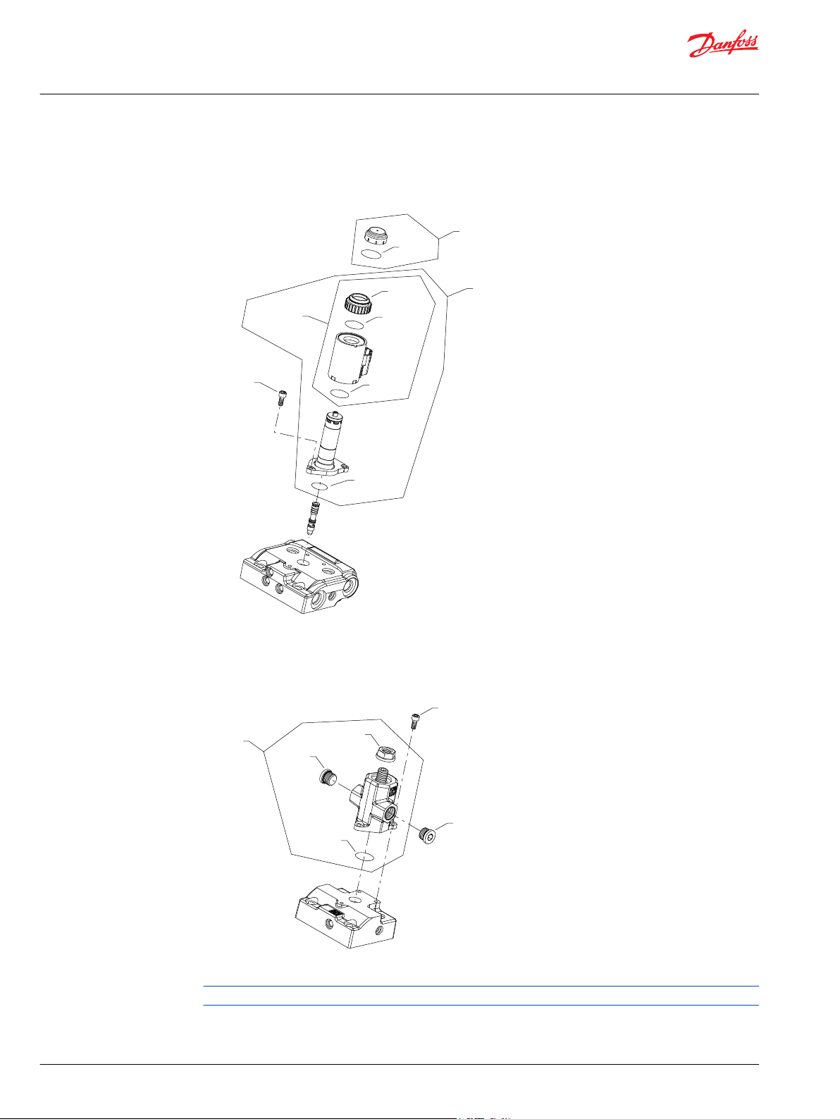
H1B servo pressure NP, NR, NT
NP configuration
NR configuration
NT configuration
50 | © Danfoss | December 2021 AX152986482121en-000611
* Included in overhaul seal kit Q210
Page 51

Parts Manual
H1B 250 Bent Axis Motor
Servo pressure supply
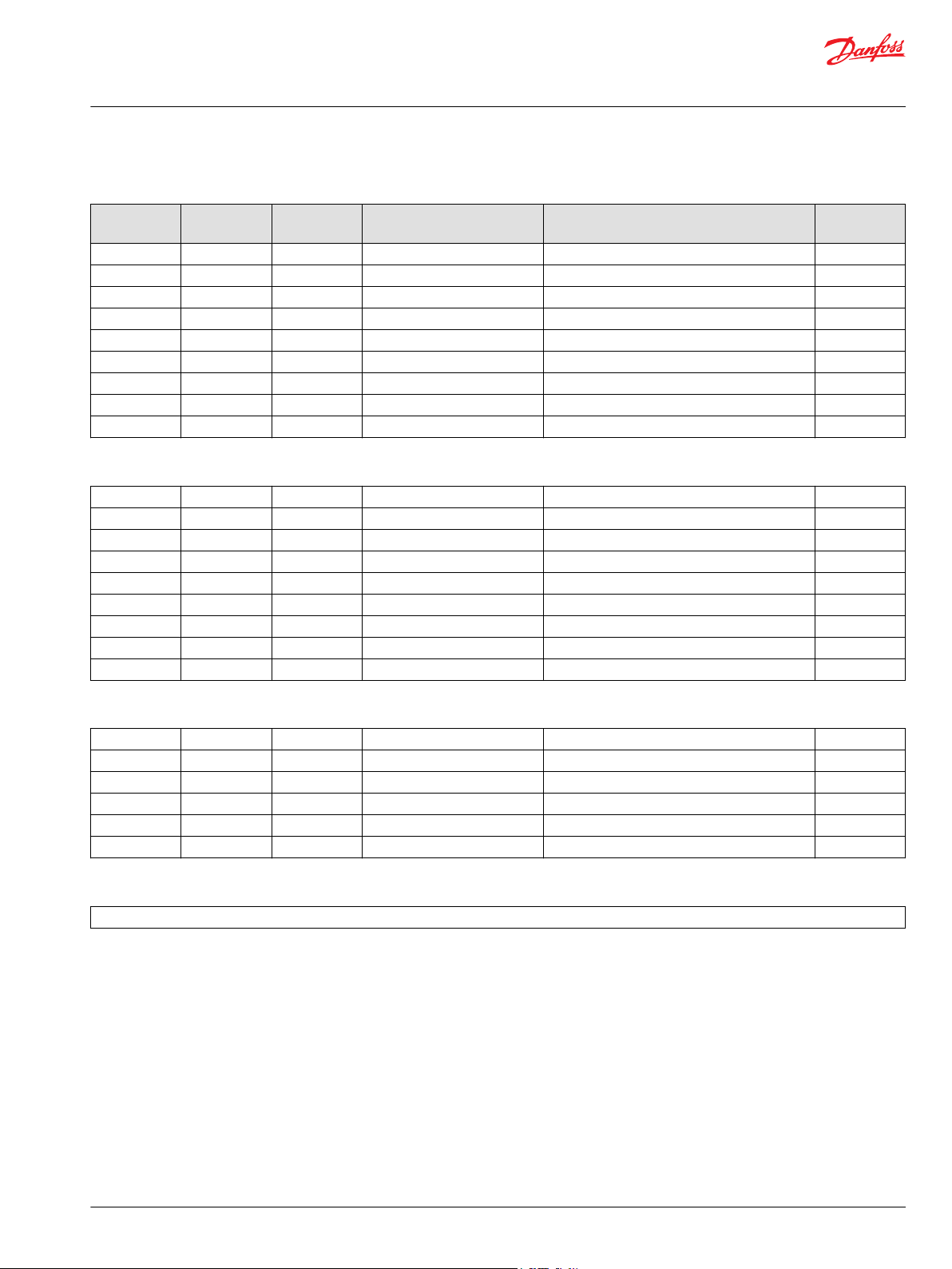
Order code: NP
Item Date Begin Date End Part Number Part Name Qty. per
C0010 11-18 11086116 Control housing, 2-position 1
C0050 11-18 140644 Plug assembly 1
C0060 11-18 11040532 Plug assembly 2
C0110 11-18 737866 (9007314-1207) Screw, M12 x 30 2
C0120 11-18 283325 (9007314-1211) Screw, M12 x 50 2
C0130 11-18 11016168 Control seal 1
Order code: NR
C0010 12-42 11123843 Control housing, proportional 1
C0025 12-42 11000893 Shuttle valve 1
C0050 12-42 140644 Plug assembly 1
C0060 12-42 11040532 Plug assembly 3
C0110 12-42 710855 Screw, M8 x 35 2
C0130 12-42 149040 Control seal 1
C0170 12-42 716860 Screw, M5 x 12 1
Model/Kit
Order code: NT
C0010 12-42 11123847 Control housing, 2-position 1
C0025 12-42 11000893 Shuttle valve 1
C0050 12-42 140644 Plug assembly 1
C0060 12-42 11040532 Plug assembly 3
C0110 12-42 737866 (9007314-1207) Screw, M12 x 30 2
C0120 12-42 283325 (9007314-1211) Screw, M12 x 50 2
C0130 12-42 11016168 Control seal 1
©
Danfoss | December 2021 AX152986482121en-000611 | 51
Page 52

E00T2
E00T3
Parts Manual
H1B 250 Bent Axis Motor
Orifice
H1B orifice A, B, C, D
A-D orifice plugs
See servo pressure supply drawing for orifice location.
52 | © Danfoss | December 2021 AX152986482121en-000611
Page 53

Parts Manual
H1B 250 Bent Axis Motor
Orifice
Order code: A
Item Date Begin Date End Part Number Part Name Qty. per
E00T2 11-18 516598 Orifice plug, 1.2 mm 1
E00T3 11-18 516598 Orifice plug, 1.2 mm 1
Order code: B
E00T2 11-18 578542 Orifice plug, 0.8 mm 1
E00T3 11-18 578542 Orifice plug, 0.8 mm 1
Order code: C
E00T2 11-18 511825 Orifice plug, 0.6 mm 1
E00T3 11-18 511825 Orifice plug, 0.6 mm 1
Order code: D
E00T2 11-18 679316 Orifice plug, 0.5 mm 1
E00T3 11-18 679316 Orifice plug, 0.5 mm 1
Model/Kit
Order code: N
No parts
©
Danfoss | December 2021 AX152986482121en-000611 | 53
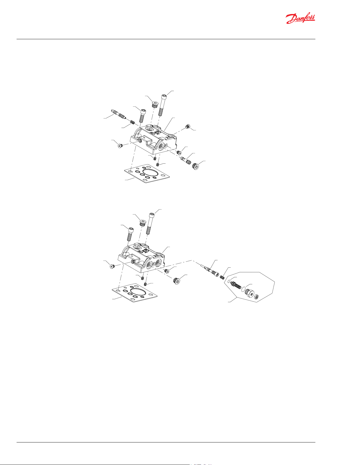
Page 54

QF080
F0100
F0160
F0010
F0020
F0070
F0040
F0030
F0090
F0050
F0120
F0100
F0160
F0060
Parts Manual
H1B 250 Bent Axis Motor
End cap
H1B 250cc end cap PA
Parts configuration
* Included in overhaul seal kit Q210
This option is available in SAE and metric configurations. Please order accordingly.
54 | © Danfoss | December 2021 AX152986482121en-000611
Page 55

Parts Manual
H1B 250 Bent Axis Motor
End cap
Order code: PA
Item Date Begin Date End Part Number Part Name Qty. per
F0010 13-23 11090018 End cap, axial ports (SAE) 1
F0010 13-23 11172638 End cap, axial ports (metric) 1
F0020 13-23 11093066 Servo piston 1
F0030 13-23 11090825 Spring guide 1
F0040 13-23 11160235 Spring 1
F0050 13-23 11093068 Setting lug 1
F0060 13-23 11008915 Setting lug pin 1
F0070 13-23 042465 Set screw, M10 x 10 1
F0090 13-23 11014186 Button head screw 1
F0100 13-23 140644 Plug assembly (SAE) 2
F0100 13-23 11178808 Plug assembly (metric) 2
F0120 13-23 703900 Screw, M16 x 70 8
F0160 13-23 140644 Plug assembly (SAE) 2
F0160 13-23 11178808 Plug assembly (metric) 2
QF080 13-23 18-16 11086155 Valve segment assembly (SB-2018-028 on page
99)
Model/Kit
1
©
Danfoss | December 2021 AX152986482121en-000611 | 55
Page 56

F0150
F0150
QF080
F0100
F0010
F0020
F0070
F0040
F0030
F0090
F0050
F0120
F0100
F0060
Parts Manual
H1B 250 Bent Axis Motor
End cap
H1B 250cc end cap PB
Parts configuration
* Included in overhaul seal kit Q210
56 | © Danfoss | December 2021 AX152986482121en-000611
Page 57

Parts Manual
H1B 250 Bent Axis Motor
End cap
Order code: PB
Item Date Begin Date End Part Number Part Name Qty. per
F0010 13-23 11090017 End cap, side ports 1
F0020 13-23 11093066 Servo piston 1
F0040 13-23 11160235 Spring 1
F0050 13-23 11093068 Setting lug 1
F0100 13-23 140644 Plug assembly 2
F0120 13-23 703900 Screw, M16 x 70 8
F0150 13-23 664524 (9005110-9000) Plug assembly 2
QF080 13-23 18-16 11086155 Valve segment assembly (SB-2018-028 on page
99)
Model/Kit
1
©
Danfoss | December 2021 AX152986482121en-000611 | 57
Page 58

F0100
F0160
F0010
F0020
F0070
F0040
F0030
F0090
F0050
F0120
F0100
F0160
F0060
F0170
Parts Manual
H1B 250 Bent Axis Motor
End cap
H1B 250cc end cap PF
Parts configuration
* Included in overhaul seal kit Q210
This option is available in SAE and metric configurations. Please order accordingly.
58 | © Danfoss | December 2021 AX152986482121en-000611
Page 59

Parts Manual
H1B 250 Bent Axis Motor
End cap
Order code: PF
Item Date Begin Date End Part Number Part Name Qty. per
F0010 13-23 11161881 End cap, axial ports (SAE) 1
F0010 13-23 11184331 End cap, axial ports (metric) 1
F0020 13-23 11093066 Servo piston 1
F0040 13-23 11160235 Spring (SAE) 1
F0040 13-23 11160235 Spring (metric) 1
F0050 13-23 11093068 Setting lug 1
F0100 13-23 140644 Plug assembly (SAE) 2
F0100 13-23 11178808 Plug assembly (metric) 2
F0120 13-23 703900 Screw, M16 x 70 8
F0160 13-23 140644 Plug assembly (SAE) 2
F0160 13-23 140644 Plug assembly (metric) 2
F0170 13-23 11124768 Edge filter 2
QF080 13-23 18-16 11086155 Valve segment assembly (SB-2018-028 on page
99)
Model/Kit
1
©
Danfoss | December 2021 AX152986482121en-000611 | 59
Page 60

QF080
F0090
F0050
F0010
F0120
F0020
F0070
F0040
F0030
F0160
F0100
F0160
F0100
F0060
Parts Manual
H1B 250 Bent Axis Motor
End cap
H1B 250cc end cap RA
Parts configuration
* Included in overhaul seal kit Q210
This option is available in SAE and metric configurations. Please order accordingly.
60 | © Danfoss | December 2021 AX152986482121en-000611
Page 61

Parts Manual
H1B 250 Bent Axis Motor
End cap
Order code: RA
Item Date Begin Date End Part Number Part Name Qty. per
F0010 13-23 11090018 End cap, axial ports (SAE) 1
F0010 16-35 11172638 End cap, axial ports (metric) 1
F0020 13-23 11093066 Servo piston 1
F0040 16-35 11160235 Spring 1
F0050 13-23 11093068 Setting lug 1
F0100 13-23 140644 Plug assembly (SAE) 2
F0100 16-35 11178808 Plug assembly (metric) 2
F0120 13-23 703900 Screw, M16 x 70 8
F0160 13-23 140644 Plug assembly (SAE) 2
F0160 16-35 11178808 Plug assembly (metric) 2
QF080 13-23 18-16 11086155 Valve segment (SB-2018-028 on page 99) 1
Model/Kit
©
Danfoss | December 2021 AX152986482121en-000611 | 61
Page 62

QF080
F0090
F0050
F0010
F0120
F0020
F0070
F0040
F0030
F0100
F0150
F0150
F0100
F0060
Parts Manual
H1B 250 Bent Axis Motor
End cap
H1B 250cc end cap RB
Parts configuration
* Included in overhaul seal kit Q210
62 | © Danfoss | December 2021 AX152986482121en-000611
Page 63

Parts Manual
H1B 250 Bent Axis Motor
End cap
Order code: RB
Item Date Begin Date End Part Number Part Name Qty. per
F0010 13-23 11090017 End cap, side ports 1
F0020 13-23 11093066 Servo piston 1
F0040 13-23 11160235 Spring 1
F0050 13-23 11093068 Setting lug 1
F0100 13-23 140644 Plug assembly 2
F0120 13-23 703900 Screw, M16 x 70 8
F0150 13-23 664524 (9005110-9000) Plug assembly 2
QF080 13-23 18-16 11086155 Valve segment (SB-2018-028 on page 99) 1
Model/Kit
©
Danfoss | December 2021 AX152986482121en-000611 | 63
Page 64

QF080
F0090
F0050
F0010
F0120
F0020
F0070
F0040
F0030
F0060
F0160
F0100
F0100
F0160
Parts Manual
H1B 250 Bent Axis Motor
End cap
H1B 250cc end cap RE
Parts configuration
* Included in overhaul seal kit Q210
64 | © Danfoss | December 2021 AX152986482121en-000611
Page 65

Parts Manual
H1B 250 Bent Axis Motor
End cap
Order code: RE
Item Date Begin Date End Part Number Part Name Qty. per
F0010 13-23 11106050 End cap, axial ports 1
F0020 13-23 11093066 Servo piston 1
F0040 13-23 11160235 Spring 1
F0050 13-23 11093068 Setting lug 1
F0100 13-23 140644 Plug assembly 2
F0120 13-23 703900 Screw, M16 x 70 8
F0160 13-23 140644 Plug assembly 2
QF080 13-23 18-16 11086155 Valve segment (SB-2018-028 on page 99) 1
Model/Kit
©
Danfoss | December 2021 AX152986482121en-000611 | 65
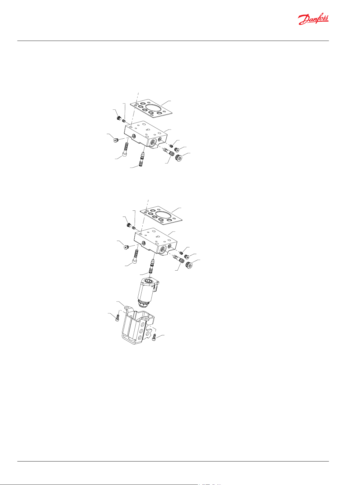
Page 66

F0090
QF080
F0010
*P0044
*P0043
F0020
F0120
F0160
F0160
F0100
Parts Manual
H1B 250 Bent Axis Motor
End cap
H1B 250cc end cap TA
Parts configuration
* Included in overhaul seal kit Q210
This option is available in SAE and metric configurations. Please order accordingly.
66 | © Danfoss | December 2021 AX152986482121en-000611
Page 67

Parts Manual
H1B 250 Bent Axis Motor
End cap
Order code: TA
Item Date Begin Date End Part Number Part Name Qty. per
F0010 13-23 11115846 End cap, axial ports (SAE) 1
F0010 16-06 11175038 End cap, axial ports (metric) 1
F0020 13-23 11140319 Servo piston assembly 1
F0090 13-23 11014186 Button head screw 1
F0100 13-23 140644 Plug assembly (SAE) 1
F0100 16-06 11178808 Plug assembly (metric) 1
F0120 13-23 703900 Screw, M16 x 70 8
F0160 13-23 140644 Plug assembly (SAE) 2
F0160 16-06 11178808 Plug assembly (metric) 2
P0043 13-23 11063016 O-ring 1
P0044 13-23 11063013 Piston ring 1
QF080 13-23 18-16 11086155 Valve segment assembly (SB-2018-028 on page
99)
Model/Kit
1
©
Danfoss | December 2021 AX152986482121en-000611 | 67
Page 68

F0090
QF080
F0010
*P0044
*P0043
F0020
F0120
F0150
F0150
F0100
Parts Manual
H1B 250 Bent Axis Motor
End cap
H1B 250cc end cap TB
Parts configuration
* Included in overhaul seal kit Q210
68 | © Danfoss | December 2021 AX152986482121en-000611
Page 69

Parts Manual
H1B 250 Bent Axis Motor
End cap
Order code: TB
Item Date Begin Date End Part Number Part Name Qty. per
F0010 13-23 11115847 End cap, side ports 1
F0020 13-23 11140319 Servo piston assembly 1
F0090 13-23 11014186 Button head screw 1
F0100 13-23 140644 Plug assembly 1
F0120 13-23 703900 Screw, M16 x 70 8
F0150 13-23 664524 (9005110-9000) Plug assembly 2
P0043 13-23 11063016 O-ring 1
P0044 13-23 11063013 Piston ring 1
QF080 13-23 18-16 11116072 Valve segment assembly (SB-2018-028 on page
99)
Model/Kit
1
©
Danfoss | December 2021 AX152986482121en-000611 | 69
Page 70

G0040
G0040
G0010
G0050
*QG050
*G0020
G0030
G0060
G0061
*G0070
G0060
G0040
*G0070
G0040
G0061
G0050
*QG050
G0010
*G0020
G0030
(DN)
(DS)
Parts Manual
H1B 250 Bent Axis Motor
Flange/housing
H1B 250cc flange/housing DN, DS
Parts configuration
* Included in overhaul seal kit Q210.
70 | © Danfoss | December 2021 AX152986482121en-000611
Page 71
Parts Manual
H1B 250 Bent Axis Motor
Flange/housing
Common parts
Item Date Begin Date End Part Number Part Name Qty. per
G0010 16-23 11180520 Housing, SAE with speed sensor port 1
G0020 16-23 519022 Lip seal 1
G0030 16-23 392423 Retaining ring 1
G0040 16-23 11007677 Pin 2
G0050 16-23 11063948 Shaft location plug assembly 1
G0060 16-23 320002 (9005110-9200) Plug assembly (SAE) 1
G0061 16-23 320002 (9005110-9200) Plug assembly (SAE) 1
G0070 16-23 11090824 Gasket 1
Order code: DN
J0010 16-23 11013290 PPU plug assembly 1
J0020 16-23 395822 (9007315-0603) Screw, M6 x 12 1
J0041 16-23 018499 (9004100-0160) O-ring 1
QG050 16-23 001123 (9004201-2500) O-ring 1
Model/Kit
Order code: DS
QG050 16-23 001123 (9004201-2500) O-ring 1
©
Danfoss | December 2021 AX152986482121en-000611 | 71
Page 72

G0040
G0040
G0010
G0050
*QG050
*G0020
G0030
*J0041
J0041
J0020
G0061
G0060
*G0070
G0040
G0040
G0010
G0050
*QG050
*G0020
G0030
*J0041
G0060
G0061
*G0070
J0010
J0020
(VC)
(VN)
Parts Manual
H1B 250 Bent Axis Motor
Flange/housing
H1B 250cc flange/housing VC, VN
Parts configuration
* Included in overhaul seal kit Q210
Option VN is available in SAE and metric configurations. Please order accordingly.
72 | © Danfoss | December 2021 AX152986482121en-000611
Page 73

Parts Manual
H1B 250 Bent Axis Motor
Flange/housing
Order code: VC
Item Date Begin Date End Part Number Part Name Qty. per
G0010 13-23 11095943 Housing, SAE with speed sensor port 1
G0030 13-23 11070170 Retaining ring 1
G0040 13-23 11007677 Pin 2
G0050 13-23 11063948 Shaft locating plug assembly 1
G0060 13-23 320002 (9005110-9200) Plug assembly 1
G0061 13-23 320002 (9005110-9200) Plug assembly 1
G0070 13-23 11090824 Gasket 1
G0120 13-23 11070158 O-ring 1
G2000 13-23 11095938 Shaft seal carrier assembly 1
QG050 13-23 001123 (9004201-2500) O-ring 1
Order code: VN
G0010 13-23 11089959 Housing, SAE flange with speed sensor port (SAE) 1
G0010 16-07 11172637 Housing, SAE flange with speed sensor port
(metric)
G0020 13-23 519022 Lip seal 1
G0030 13-23 392423 Retaining ring 1
G0040 13-23 11007677 Pin 2
G0050 13-23 11063948 Shaft locating plug assembly 1
G0060 13-23 320002 (9005110-9200) Plug assembly (SAE) 1
G0060 16-07 11164204 Plug assembly (metric 1
G0061 13-23 320002 (9005110-9200) Plug assembly (SAE) 1
G0061 16-07 11164204 Plug assembly (metric) 1
G0070 13-23 11090824 Gasket 1
J0010 13-23 11013290 PPU plug assembly 1
J0020 13-23 395822 (9007315-0603) Screw, M6 x 12 1
J0041 13-23 11013397 O-ring 1
QG050 13-23 001123 (9004201-2500) O-ring 1
Model/Kit
1
©
Danfoss | December 2021 AX152986482121en-000611 | 73
Page 74

*G0070
G0040
G0040
G0010
G0050
*QG050
*G0020
G0030
G0060
G0061
G0040
G0040
G0010
G0050
*QG050
*G0020
G0120
L514
G0200
G0030
G0060
*G0070
G0061
(VS)
(VT)
Parts Manual
H1B 250 Bent Axis Motor
Flange/housing
H1B 250cc flange/housing VS, VT
Parts configuration
* Included in overhaul seal kit Q210
Option VS is available in SAE and metric configurations. Please order accordingly.
74 | © Danfoss | December 2021 AX152986482121en-000611
Page 75

Parts Manual
H1B 250 Bent Axis Motor
Flange/housing
Order code: VS
Item Date Begin Date End Part Number Part Name Qty. per
G0010 13-23 11089959 Housing, SAE flange with speed sensor port (SAE) 1
G0010 15-45 11172637 Housing, SAE flange with speed sensor port
(metric)
G0020 13-23 519022 Lip seal 1
G0030 13-23 392423 Retaining ring 1
G0040 13-23 11007677 Pin 2
G0050 13-23 11063948 Shaft locating plug assembly 1
G0060 13-23 320002 (9005110-9200) Plug assembly (SAE) 1
G0060 15-45 11164204 Plug assembly (metric) 1
G0061 13-23 320002 (9005110-9200) Plug assembly (SAE) 1
G0061 15-45 11164204 Plug assembly (metric) 1
G0070 13-23 11090824 Gasket 1
QG050 13-23 001123 (9004201-2500) O-ring 1
Model/Kit
1
Order code: VT
G0010 14-27 11095943 Housing, SAE flange with speed sensor port 1
G0020 14-27 519022 Lip seal 1
G0030 14-27 11070170 Retaining ring 1
G0040 14-27 11007677 Pin 2
G0050 14-27 11063948 Shaft locating plug assembly 1
G0060 14-27 320002 (9005110-9200) Plug assembly 1
G0061 14-27 320002 (9005110-9200) Plug assembly 1
G0070 14-27 11090824 Gasket 1
G0120 14-27 11070158 O-ring 1
G0200 14-27 11152435 Seal carrier assembly 1
L514 14-27 521664 Lip seal 1
QG050 14-27 001123 (9004201-2500) O-ring 1
©
Danfoss | December 2021 AX152986482121en-000611 | 75
Page 76

QH300
QH030
H0180
QH300
QH030
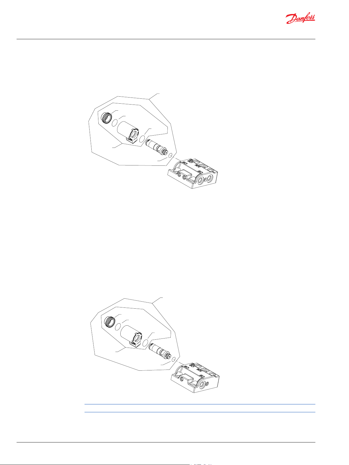
(DS, FS, LS, PS)
(DN, FN, LN)
Parts Manual
H1B 250 Bent Axis Motor
Shaft
H1B 250cc shaft DN-PS
Parts configuration
76 | © Danfoss | December 2021 AX152986482121en-000611
Page 77

Parts Manual
H1B 250 Bent Axis Motor
Shaft
Order code: DN
Item Date Begin Date End Part Number Part Name Qty. per
QH030 13-23 11100639 Piston ring kit 1
QH300 13-23 11094973 Shaft assembly, 27 tooth, 16/32 pitch 1
Order code: DS
H180 13-23 11086231 Speed ring 1
QH030 13-23 11100639 Piston ring kit 1
QH300 13-23 11094970 Shaft assembly, 27 tooth, 16/32 pitch, speed ring 1
Order code: FN
QH030 13-23 11100639 Piston ring kit 1
QH300 13-23 11086222 Shaft assembly, 15 tooth 1
Order code: FS
H180 13-23 11086231 Speed ring 1
QH030 13-23 11100639 Piston ring kit 1
QH300 13-23 11086198 Shaft assembly, 15 tooth, speed ring 1
Model/Kit
Order code: LS
H0180 17-33 11086231 Speed ring 1
QH030 17-33 11100639 Piston ring kit 1
QH300 17033 11198219 Shaft assembly, 24 tooth 1
Order code: LN
QH030 18-26 11100639 Piston ring kit 1
QH300 18-26 11221814 Shaft assembly 1
Order code: PS
H180 13-23 11086231 Speed ring 1
QH030 13-23 11100639 Piston ring kit 1
QH300 13-23 11096985 Shaft assembly, 27 tooth, 16/32 pitch, speed ring 1
©
Danfoss | December 2021 AX152986482121en-000611 | 77
Page 78

J0010
*J0041
J0020
*J0041
J0010
J0020
J0010
*J0041
J0020
J0300
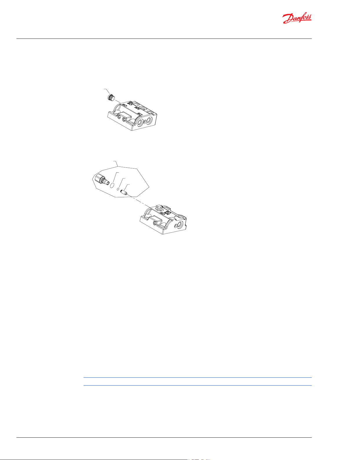
(P)
(B, C, S)
(D)
Parts Manual
H1B 250 Bent Axis Motor
Speed sensor
H1B 250cc speed sensor
Parts configuration
* Included in overhaul seal kit Q210
78 | © Danfoss | December 2021 AX152986482121en-000611
Page 79

Parts Manual
H1B 250 Bent Axis Motor
Speed sensor
Order code: B
Item Date Begin Date End Part Number Part Name Qty. per
J0010 12-15 11232698 Speed sensor assembly 1
J0020 12-15 395822 (9007315-0603) Screw, M6 x 12 1
J0041 12-15 11013397 O-ring 1
Order code: C
J0010 14-41 11157520 Speed sensor assembly 1
J0020 14-41 395822 (9007315-0603) Screw, M6 x 12 1
Order code: D
J0010 16-49 149055 Speed sensor 1
J0020 16-49 072264 Screw, M6 x 40 1
J0041 16-49 11013397 O-ring 1
J0300 16-49 11187156 Protective cover 1
Model/Kit
Order code: N
No parts
Order code: P
J0010 13-23 11013290 Plug assembly 1
J0020 13-23 395822 (9007315-0603) Screw, M6 x 12 1
J0041 13-23 11013397 O-ring 1
Order code: S
J0010 13-23 149055 Speed sensor 1
J0020 13-23 395822 (9007315-0603) Screw, M6 x 12 1
J0041 13-23 11013397 O-ring 1
©
Danfoss | December 2021 AX152986482121en-000611 | 79
Page 80

K0040
*QK040
K0010
*QK050
K0050
K0040
*QK040
K0010
*QK050
K0050
K0010
*QK050
K0050
K0040
*QK040
K0020
K0020
*QK050
K0040
*QK040
K0010
K0050
K0040
*QK040
K0010
*QK050
K0050
K0010
*QK050
K0050
K0040
*QK040
(A & N)(A & N) (B)(B)
(C)(C)
(D)(D)
(E)(E) (F)(F)
Parts Manual
H1B 250 Bent Axis Motor
Loop flushing
H1B 250cc loop flushing A-N
Parts configuration
* Included in overhaul seal kit Q210
80 | © Danfoss | December 2021 AX152986482121en-000611
Page 81

Parts Manual
H1B 250 Bent Axis Motor
Loop flushing
Order code: A and N
Item Date Begin Date End Part Number Part Name Qty. per
K0010 11-18 19-43 11031106 Spool (SB-2020-038 on page 101) 1
K0010 19-44 11165542 Spool 1
K0040 11-18 11160780 Plug/spring assembly 1
K0050 11-18 11160780 Plug/spring assembly 1
QK040 11-18 149052 O-ring 1
QK050 11-18 149052 O-ring 1
Order code: B
K0010 15-45 19-43 11101037 Spool (SB-2020-038 on page 101) 1
K0010 19-44 11165542 Spool 1
K0020 15-45 11101439 Spring/plug assembly 2
K0040 15-45 11101035 Plug assembly 1
K0050 15-45 11101035 Plug assembly 1
QK040 15-45 149052 O-ring 1
QK050 15-45 149052 O-ring 1
Model/Kit
Order code: C
K0010 12-15 19-43 11031106 Spool (SB-2020-038 on page 101) 1
K0010 19-44 11165542 Spool 1
K0040 12-15 11115123 Plug assembly 1
K0050 12-15 11160780 Plug/spring assembly 1
QK040 12-15 149052 O-ring 1
QK050 12-15 149052 O-ring 1
Order code: D
K0010 12-15 11031106 Spool 1
K0040 12-15 11160780 Plug/spring assembly 1
K0050 12-15 11115123 Plug assembly 1
QK040 12-15 149052 O-ring 1
QK050 12-15 149052 O-ring 1
Parts continue to the next 2 pages.
©
Danfoss | December 2021 AX152986482121en-000611 | 81
Page 82

K0040
*QK040
K0010
*QK050
K0050
K0040
*QK040
K0010
*QK050
K0050
K0010
*QK050
K0050
K0040
*QK040
K0020
K0020
*QK050
K0040
*QK040
K0010
K0050
K0040
*QK040
K0010
*QK050
K0050
K0010
*QK050
K0050
K0040
*QK040
(A & N)(A & N) (B)(B)
(C)(C)
(D)(D)
(E)(E) (F)(F)
Parts Manual
H1B 250 Bent Axis Motor
Loop flushing
Parts configuration
* Included in overhaul seal kit Q210
82 | © Danfoss | December 2021 AX152986482121en-000611
Page 83

Parts Manual
H1B 250 Bent Axis Motor
Loop flushing
Order code: E
Item Date Begin Date End Part Number Part Name Qty. per
K0010 14-41 11157411 Spool 1
K0040 14-41 11160780 Plug/spring assembly 1
K0050 14-41 11160780 Plug/spring assembly 1
QK040 14-41 149052 O-ring 1
QK050 14-41 149052 O-ring 1
Order code: F
K0010 14-41 11157409 Spool 1
K0040 14-41 11158323 Plug/spring assembly 1
K0050 14-41 11158323 Plug/spring assembly 1
QK040 14-41 149052 O-ring 1
QK050 14-41 149052 O-ring 1
Model/Kit
©
Danfoss | December 2021 AX152986482121en-000611 | 83
Page 84

*L0150
*L0150
L0100
*L0150
*L0150
L0100
L0100
L0100
*L0150
B0026
B0020
*B0034
L0010
B0028
B0024
L0100
(NN)(NN)
(05-50)(05-50)
(NN)(NN)
(05-50)(05-50)
(E2, E3, E4)(E2, E3, E4)
Parts Manual
H1B 250 Bent Axis Motor
Loop flushing
H1B loop flushing 05-50
Parts configuration
Generic end caps shown
* Included in overhaul seal kit Q210
84 | © Danfoss | December 2021 AX152986482121en-000611
Page 85

Parts Manual
H1B 250 Bent Axis Motor
Loop flushing
Order code: 05
Item Date Begin Date End Part Number Part Name Qty. per
L0100 11-18 11008698 Loop flushing relief valve, 5L/min 1
L0150 11-18 149052 O-ring 1
Order code: 10
L0100 11-18 11003448 Loop flushing relief valve, 10L/min 1
L0150 11-18 149052 O-ring 1
Order code: 15
L0100 11-18 11003450 Loop flushing relief valve, 15L/min 1
L0150 11-18 149052 O-ring 1
Order code: 20
L0100 11-18 11001676 Loop flushing relief valve, 20L/min 1
L0150 11-18 149052 O-ring 1
Model/Kit
Order code: 30
L0100 13-23 11008700 Loop flushing relief valve, 30L/min 1
L0150 13-23 149052 O-ring 1
Order code: 40
L0100 13-23 11008701 Loop flushing relief valve, 40L/min 1
L0150 13-23 149052 O-ring 1
Order code: 50
L0100 13-23 11001697 Loop flushing relief valve, 50L/min 1
L0150 13-23 149052 O-ring 1
Part numbers for options E2, E3, E4, and NN are continued on the next page.
©
Danfoss | December 2021 AX152986482121en-000611 | 85
Page 86

*L0150
*L0150
L0100
*L0150
*L0150
L0100
L0100
L0100
*L0150
B0026
B0020
*B0034
L0010
B0028
B0024
L0100
(NN)(NN)
(05-50)(05-50)
(NN)(NN)
(05-50)(05-50)
(E2, E3, E4)(E2, E3, E4)
Parts Manual
H1B 250 Bent Axis Motor
Loop flushing
H1B loop flushing E2, E3, E4, NN
Parts configuration
Generic end caps shown
* Included in overhaul seal kit Q210
86 | © Danfoss | December 2021 AX152986482121en-000611
Page 87

Parts Manual
H1B 250 Bent Axis Motor
Loop flushing
Order code: E2
Item Date Begin Date End Part Number Part Name Qty. per
B0024 13-23 11031608 O-ring 1
B0026 13-23 11027046 Coil nut 1
B0028 13-23 063172 O-ring 1
B0034 13-23 085043 (9004201-3700) O-ring 1
C2000 13-23 11031763 Coil kit, 12 volt 1
L0100 13-23 11096735 Loop flushing relief valve, 12v, 10L/min 1
L0150 13-23 149052 O-ring 1
L1000 13-23 11013615 Solenoid valve, 12v 1
Order code: E3
B0024 13-23 11031608 O-ring 1
B0026 13-23 11027046 Coil nut 1
B0028 13-23 063172 O-ring 1
B0034 13-23 085043 (9004201-3700) O-ring 1
C2000 13-23 11031763 Coil kit, 12 volt 1
L0100 13-23 11096736 Loop flushing relief valve, 12v, 15L/min 1
L0150 13-23 149052 O-ring 1
L1000 13-23 11013615 Solenoid valve, 12v 1
Model/Kit
Order code: E4
B0024 16-06 11031608 O-ring 1
B0026 16-06 11027046 Coil nut 1
B0028 16-06 063172 O-ring 1
B0034 16-06 085043 (9004201-3700) O-ring 1
C2000 16-06 11031763 Coil kit 12 volt 1
L0150 16-06 149052 O-ring 1
L0100 16-06 11175555 Loop flushing relief valve, 12v, 20L/min 1
L1000 16-06 11013615 Solenoid valve, 12v 1
Order code: NN
L0100 11-18 11027278 Plug assembly 1
L0150 11-18 149052 O-ring 1
©
Danfoss | December 2021 AX152986482121en-000611 | 87
Page 88

M0030
QM010
QM020
QM050
QM050
(HN)
(HP)
Parts Manual
H1B 250 Bent Axis Motor
Special hardware and displacement
H1B 250cc special hardware HN, HP
Parts configuration
88 | © Danfoss | December 2021 AX152986482121en-000611
Page 89

Parts Manual
H1B 250 Bent Axis Motor
Special hardware and displacement
Order code: HN
Item Date Begin Date End Part Number Part Name Qty. per
M0030 18-06 11195864 Bearing plate 1
QM010 18-06 11086121 Synch shaft assembly 1
QM020 18-06 11188008 Cylinder block assembly 1
QM050 18-06 11202372 Valve segment assembly (2-position) 1
Order code: HP
M0030 18-06 11195864 Bearing plate 1
QM010 18-06 11086121 Synch shaft assembly 1
QM020 18-06 11188008 Cylinder block assembly 1
QM050 18-06 11187971 Valve segment assembly (proportional) 1
Model/Kit
©
Danfoss | December 2021 AX152986482121en-000611 | 89
Page 90

M0030
QM020
QM010
QM050
QM050
(NP)(NP)
(NN)(NN)
Parts Manual
H1B 250 Bent Axis Motor
Special hardware and displacement
H1B 250cc special hardware NN, NP
Parts configuration
90 | © Danfoss | December 2021 AX152986482121en-000611
Page 91

Parts Manual
H1B 250 Bent Axis Motor
Special hardware and displacement
Order code: NN
Item Date Begin Date End Part Number Part Name Qty. per
QM010 13-23 11086121 Synch shaft assembly 1
QM020 13-23 11086152 Cylinder block assembly 1
M0030 13-23 515370 Bearing plate 1
QM050 18-16 11116072 Valve segment assembly (2-position) 1
Order code: NP
QM010 13-23 11086121 Synch shaft assembly 1
QM020 13-23 11086152 Cylinder block assembly 1
M0030 13-23 515370 Bearing plate 1
QM050 18-16 11086155 Valve segment assembly (proportional) 1
Model/Kit
©
Danfoss | December 2021 AX152986482121en-000611 | 91
Page 92

N1000
*N2000
Q1200
N1000
QN070
N1000
(AB2)(AB2)
(000-169, AB2)(000-169, AB2)
(MB0)(MB0)
Parts Manual
H1B 250 Bent Axis Motor
Special hardware and displacement
H1B 250cc minimum displacement
Parts configuration
* Included in overhaul seal kit Q210
92 | © Danfoss | December 2021 AX152986482121en-000611
Page 93
Parts Manual
H1B 250 Bent Axis Motor
Special hardware and displacement
Order code: 000-052
Item Date Begin Date End Part Number Part Name Qty. per
N1000 13-23 750646 Set screw, 0-52cc, M12 x 75 1
N2000 13-23 076042 Seal nut, M12 1
Q1200 13-23 770842 Plastic cap, green 1
Order code: 053-103
N1000 13-23 749564 Set screw, 53-103cc, M12 x 90 1
N2000 13-23 076042 Seal nut, M12 1
Q1200 13-23 770842 Plastic cap, green 1
Order code: 104-169
N1000 13-23 11094518 Set screw, 104-169cc, M12 x 110 1
N2000 13-23 076042 Seal nut, M12 1
Q1200 13-23 770842 Plastic cap, green 1
Model/Kit
Order code: AB2
N1000 13-23 11106517 Set screw, 200cc, M12 x 40 1
N2000 13-23 076042 Seal nut, M12 1
N0040 13-23 11157830 Spacer, 69.16mm 1
Q1200 13-23 770842 Plastic cap, green 1
Order code: MB0
N1100 13-23 11161812 Seal plug assembly 1
QN070 13-23 11001952 O-ring 1
©
Danfoss | December 2021 AX152986482121en-000611 | 93
Page 94

P0010
P0020
*P0030
P0050
*P0044
*P0043
P0040
P0200
P0100
P0100
(B, C, E, N)
(Q)(Q)
(R, S, T)(R, S, T)
Parts Manual
H1B 250 Bent Axis Motor
Special hardware and displacement
H1B 250cc maximum displacement
Parts configuration
* Included in overhaul seal kit Q210
94 | © Danfoss | December 2021 AX152986482121en-000611
Page 95

C
Parts Manual
H1B 250 Bent Axis Motor
Special hardware and displacement
Caution
During removal of screw (P0050) and set screw (F0070), the servo piston assembly will be subjected to
high torque and may create a pinch point for fingers. Use caution when disassembling these components
from the servo piston. For more information, see SB-2019-017 on page 100.
Order code: B
Item Date Begin Date End Part Number Part Name Qty. per
P0010 18-13 11001110 Servo piston cover 1
P0020 18-13 737866 Screw, M12 x 30 4
P0030 18-13 11050757 O-ring 1
P0040 18-13 11212757 Servo piston assembly 1
P0043 18-13 11063016 O-ring 1
P0044 18-13 11063013 Piston ring 1
P0050 18-13 11069403 Screw, M14 x 35 1
Order code: C
P0010 13-23 11001110 Servo piston cover 1
P0020 13-23 737866 (9007314-1207) Screw, M12 x 30 4
P0030 13-23 11050757 O-ring 1
P0040 13-23 11132145 Servo piston assembly 1
P0043 13-23 11063016 O-ring 1
P0044 13-23 11063013 Piston ring 1
P0050 13-23 11069403 Screw, M14 x 35 1
Model/Kit
Order code: E
P0010 13-23 11001110 Servo piston cover 1
P0020 13-23 737866 (9007314-1207) Screw, M12 x 30 4
P0030 13-23 11050757 O-ring 1
P0040 13-23 11125475 Servo piston assembly 1
P0043 13-23 11063016 O-ring 1
P0044 13-23 11063013 Piston ring 1
P0050 13-23 11069403 Screw, M14 x 35 1
Parts continue to next 2 pages.
©
Danfoss | December 2021 AX152986482121en-000611 | 95
Page 96

P0010
P0020
*P0030
P0050
*P0044
*P0043
P0040
P0200
P0100
P0100
(B, C, E, N)
(Q)(Q)
(R, S, T)(R, S, T)
Parts Manual
H1B 250 Bent Axis Motor
Special hardware and displacement
Parts configuration
* Included in overhaul seal kit Q210
96 | © Danfoss | December 2021 AX152986482121en-000611
Page 97

C
Parts Manual
H1B 250 Bent Axis Motor
Special hardware and displacement
Caution
During removal of screw (P0050) and set screw (F0070), the servo piston assembly will be subjected to
high torque and may create a pinch point for fingers. Use caution when disassembling these components
from the servo piston. For more information, see SB-2019-017 on page 100.
Order code: N
Item Date Begin Date End Part Number Part Name Qty. per
P0010 13-23 11001110 Servo piston cover 1
P0020 13-23 737866 (9007314-1207) Screw, M12 x 30 4
P0030 13-23 11050757 O-ring 1
P0040 13-23 11062354 Servo piston assembly 1
P0043 13-23 11063016 O-ring 1
P0044 13-23 11063013 Piston ring 1
P0050 13-23 11069403 Screw, M14 x 35 1
Order code: Q
P0100 14-27 293225 Screw, M10 x 30 1
Model/Kit
Order code: R
P0100 14-27 293225 Screw, M10 x 30 1
P0200 14-27 672071 Spacer, 4.50mm 1
Order code: S
P0100 13-23 293225 Screw, M10 x 30 1
P0200 13-23 318683 Spacer, 9.00mm 1
Order code: T
P0100 14-27 727586 Screw, M10 x 35 1
P0200 14-27 643098 Spacer, 14.00mm 1
Order code: Z
No parts
©
Danfoss | December 2021 AX152986482121en-000611 | 97
Page 98

Parts Manual
H1B 250 Bent Axis Motor
Overhaul seal kit
H1B 250cc seal kit
Item Date Begin Date End Part Number Part Name Qty. per
Q210 13-23 11172555 Overhaul seal kit, H1B250 1
B0034 13-23 085043 (9004201-3700) O-ring, 11.89 x 1.98, nitrile 2
B0035 13-23 11001952 O-ring, 18.00 x 1.50, nitrile 1
C0130 13-23 149040 Control seal 1
C0130 13-23 11016168 Control seal, 2-position 1
G0020 13-23 519022 Lip seal 1
G0070 13-23 11090824 End cap gasket, H1B250 1
J0041 13-23 11013397 O-ring, 15.60 x 1.78, nitrile 1
L0150 13-23 149052 O-ring, 15.30 x 2.20, nitrile 1
M223 13-23 085043 (9004201-3700) O-ring, 11.89 x 1.98, nitrile 1
M224 13-23 732479 (9004105-0100) O-ring, 6.07 x 1.78, viton 1
N2000 13-23 076042 Seal nut, M12 1
P0030 13-23 11050757 O-ring, 47.00 x 3.00, nitrile 1
P0043 13-23 11063016 O-ring, 26.64 x 2.62, nitrile 1
P0044 13-23 11063013 Piston ring 1
Q1200 13-23 770842 Plastic cap, green 1
QC160 13-23 039297 (9004201-1200) O-ring, 6.07 x 1.63, nitrile 1
QG050 13-23 001123 (9004201-2500) O-ring, 8.92 x 1.83, nitrile 1
QG055 13-23 039297 (9004201-1200) O-ring, 6.07 x 1.63, nitrile 1
QK0040 13-23 149052 O-ring, 15.30 x 2.20, nitrile 2
QK0050 13-23 149052 O-ring, 15.30 x 2.20, nitrile 2
Model/Kit
98 | © Danfoss | December 2021 AX152986482121en-000611
Page 99

Two position valve segment
Special hardware feature NN
Proportional valve segment
Special hardware feature NP
Parts Manual
H1B 250 Bent Axis Motor
Service bulletin
SB-2018-028
Products affected
H1B motors
Subject
Parts manual change for valve segment assembly
Description
Danfoss has reorganized topics in the Parts Manual for H1B 60cc, 80cc, 110cc, 160cc, 210cc and 250cc
motors. The valve segment assembly (Item QF080) has been moved to the “Special Hardware/Common
Parts” section (Option M). It was formerly located in the “End Cap” section (Option F).
Because of the move, 2-position and proportional valve segments will need to be included in their own
order code designation. The order code for 2-position valve segments will be NN and the order code for
proportional valve segments will be NP.
Part numbers have not changed.
©
Danfoss | December 2021 AX152986482121en-000611 | 99
Models affected
H1B 60, 80, 110, 160, 210 and 250cc motors
Serial numbers
This change became effective at 18-12-xxxxx
Part number affected
Not applicable
Parts disposition
Not applicable
Page 100

C
QM050
F0020
(servo piston with
setting lug bore)
F0050 (setting lug)
P0040
P0050
Rear view of valve segment
proportional controls
Parts Manual
H1B 250 Bent Axis Motor
Service bulletin
SB-2019-017
Products affected
H1 Bent Axis Motors Size 060/080/110/160/210/250
Subject
Potential injury risk on motors with proportional control servo systems
Description
Danfoss Power Solutions has identified a potential safety concern when performing disassembly and
reassembly of the H1B bent axis motors. Specifically, when removing and installing the servo piston
assembly, it is important the instructions as documented within the H1B Bent Axis Variable Displacement
Motors Repair Instructions (document AX152886484588) are strictly followed.
Caution
Failure to follow these instructions while performing a repair can result in a severe laceration or finger
amputation injury.
Injury may occur if the removal of the servo piston bolt (P0050) is performed after the end cap has been
removed along with the valve segment (QM050) and setting lug (F0050). If torque is applied to the servo
piston bolt (P0050) while an operator’s fingers are in proximity to the empty and exposed setting lug
bore, a severe laceration or finger amputation injury may occur.
The risk of injury is also present during the reassembly of the servo piston assembly (P0040 and F0020) in
the end cap. If torque is applied to the servo piston bolt (P0050) while an operator’s fingers are in the
proximity to the empty and exposed setting lug bore, a severe laceration or finger amputation injury may
occur.
It is important that the setting lug and valve segment (QM050) are properly installed prior to installing
and torquing the servo piston bolt (P0050).
100 | © Danfoss | December 2021 AX152986482121en-000611
 Loading...