

Page 1
Technical Information
ATEX Certified
Bent Axis Variable Displacement Motors
H1B060/080/110/160/210/250
www.danfoss.com
Page 2

Technical Information
ATEX Certified Bent Axis Variable Displacement Motors – H1B 060/080/110/160/210/250
Revision history Table of revisions
Date Changed Rev
April 2022 Updated literature references 0102
June 2021 First edition 0101
2 | © Danfoss | April 2022 BC382476944585en-000102
Page 3

Technical Information
ATEX Certified Bent Axis Variable Displacement Motors – H1B 060/080/110/160/210/250
Contents
General Information
ATEX Introduction............................................................................................................................................................................4
Explosive atmosphere.....................................................................................................................................................................4
Explosion triangle....................................................................................................................................................................... 4
General zone classification...................................................................................................................................................... 4
Equipment category and zones.............................................................................................................................................5
Contents of marking.................................................................................................................................................................. 6
Marking of Danfoss Bent Axis motors..................................................................................................................................7
Production place and date of motors..................................................................................................................................8
Example ATEX label - H1B........................................................................................................................................................8
Maximum Surface Temperature
Viscosity and temperature for H1B motors.............................................................................................................................9
Master Model Code
H1B ATEX Displacement, Product Version, Port Configuration.................................................................................... 10
ATEX Certified Versions of H1B motors............................................................................................................................ 10
Control options...............................................................................................................................................................................11
PCOR and BPD options................................................................................................................................................................ 12
Threshold setting and orifice options.................................................................................................................................... 13
Endcap, flange and housing options......................................................................................................................................14
Shaft, sensor, and loop flushing shuttle system options.................................................................................................15
Loop flushing and special hardware options...................................................................................................................... 16
Minimum and maximum displacement options................................................................................................................17
PCOR pressure setting, paint and nametag options.........................................................................................................18
Technical Specifications
ATEX technical specifications....................................................................................................................................................19
Ambient temperature.................................................................................................................................................................. 19
Oil types / Operating fluids.........................................................................................................................................................19
Oil temperature.........................................................................................................................................................................19
Viscosity........................................................................................................................................................................................19
©
Danfoss | April 2022 BC382476944585en-000102 | 3
Page 4
Ignitable
substance (Gas)
Oxygen Source of ignition
(Spark or heat)
P301 800
Technical Information
ATEX Certified Bent Axis Variable Displacement Motors – H1B 060/080/110/160/210/250
General Information
ATEX Introduction
The ATEX Directive 2014/34/EU specifies the minimum safety requirements for equipment intended for
use in potentially explosive atmospheres in European Union member states. ATEX is derived from the
French term ATmosphères EXplosives.
Hydraulic motors are designed for mobile and stationary applications. Some motors are used in related
applications, where locations are classified as hazardous areas.
The equipment intended for use in hazardous areas are divided into two groups:
Group I: Equipment intended for use in underground parts of mines (mining equipment).
Group II: Equipment intended for use in other places than mines (non-mining equipment).
The Danfoss hydraulic motors, type H1B are intended for use in Group II applications.
Explosive atmosphere
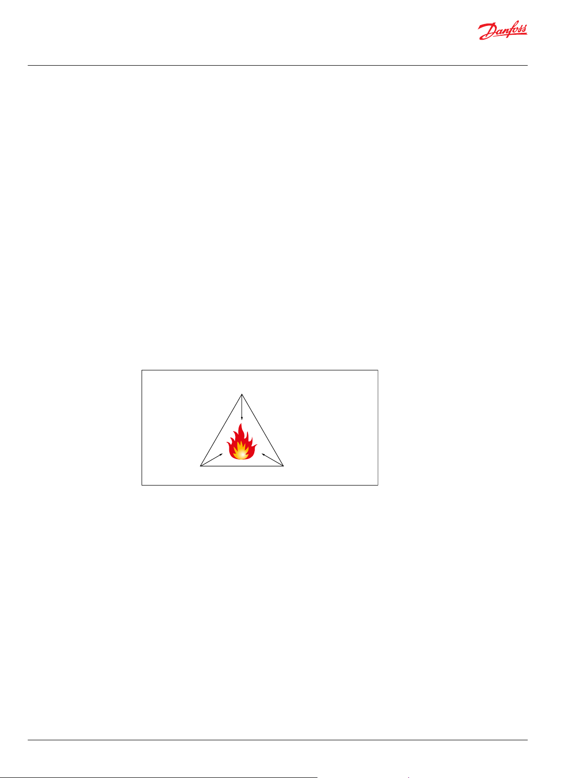
Explosion triangle
A “hazardous area” is defined as an area in which the atmosphere contains, or may contain in sufficient
quantities, flammable or explosive gases, dusts or vapours. In such an atmosphere a fire or explosion is
possible when three basic conditions are met. This is often referred to as the “hazardous area” or
“explosion” triangle.
An atmosphere with the potential to become an explosive atmosphere during operating conditions
and/or under the influence of the surroundings is defined as a potentially explosive atmosphere.
Products covered by directive 2014/34/EU are defined as intended for use in potentially explosive
atmospheres. Removing one of the elements eliminates all risk of explosion.
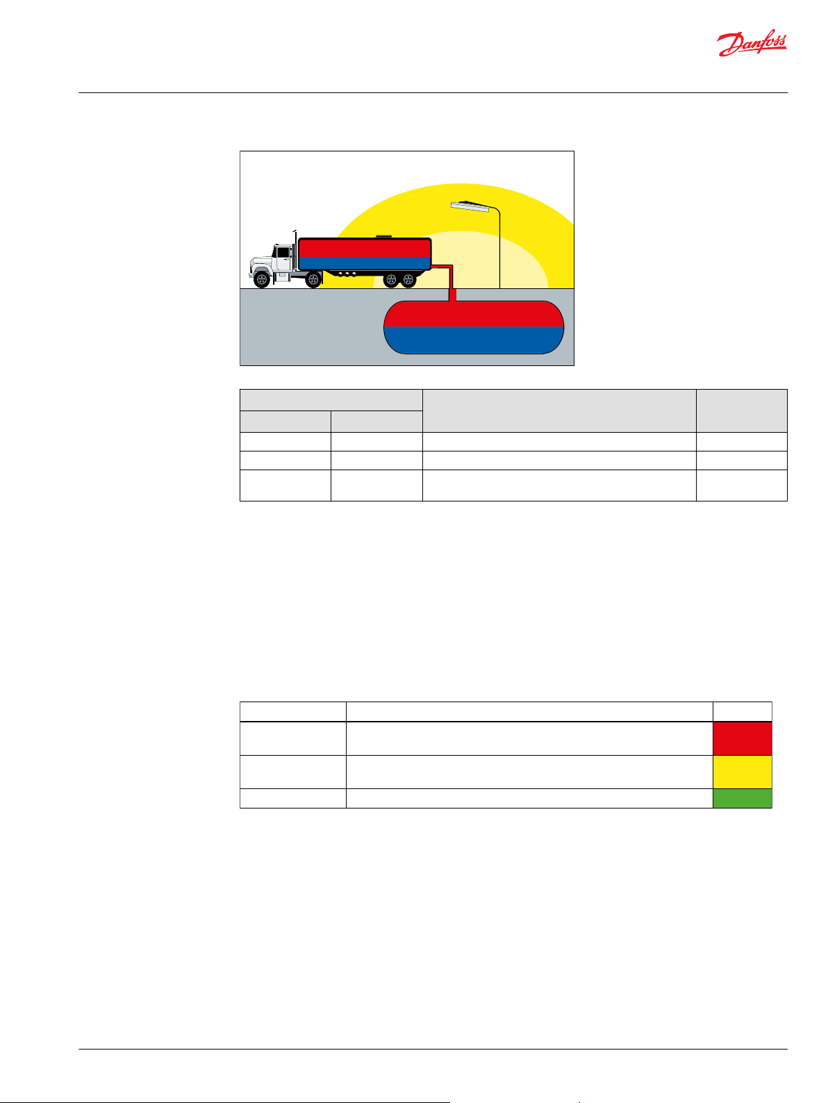
General zone classification
Directive 99/92/EC divides the Hazardous areas into zones and defines criteria by which products are
categorized within these zones; Zone 0 / 20 is the most restrictive and Zones 1 / 21 and 2 / 22 are less
restrictive. The following table describes the zones in an installation where there is a potential for
explosive atmospheres. The owner of the installation must analyze and assess the area in which the
explosive gas/dust mixture may occur, and if necessary must divide it into zones. This process of zoning
then allows the correct plant and equipment to be selected for use in the area.
4 | © Danfoss | April 2022 BC382476944585en-000102
Page 5
Zone 0
Zone 0
Zone 2
Zone 1
F301 801
Degree of protection Protection
Category
Very high Two independent protection measures or safe if two errors occur
independently
Category 1
High
Safe in normal operation and in anticipated case of commonly
occurring errors
Category 2
Normal Safe in normal operation
Category 3
P301 802
Technical Information
ATEX Certified Bent Axis Variable Displacement Motors – H1B 060/080/110/160/210/250
General Information
Zones Presence of potentially explosive atmosphere Type of risk
Gas (G) Dust (D)
0 20 Present continuously or for long periods Permant
1 21 Likely to occur in normal operation occasionally Potential
2 22 Not likely to occur in normal operation but. If it does
occur, will persist for a short period of time
Minimal
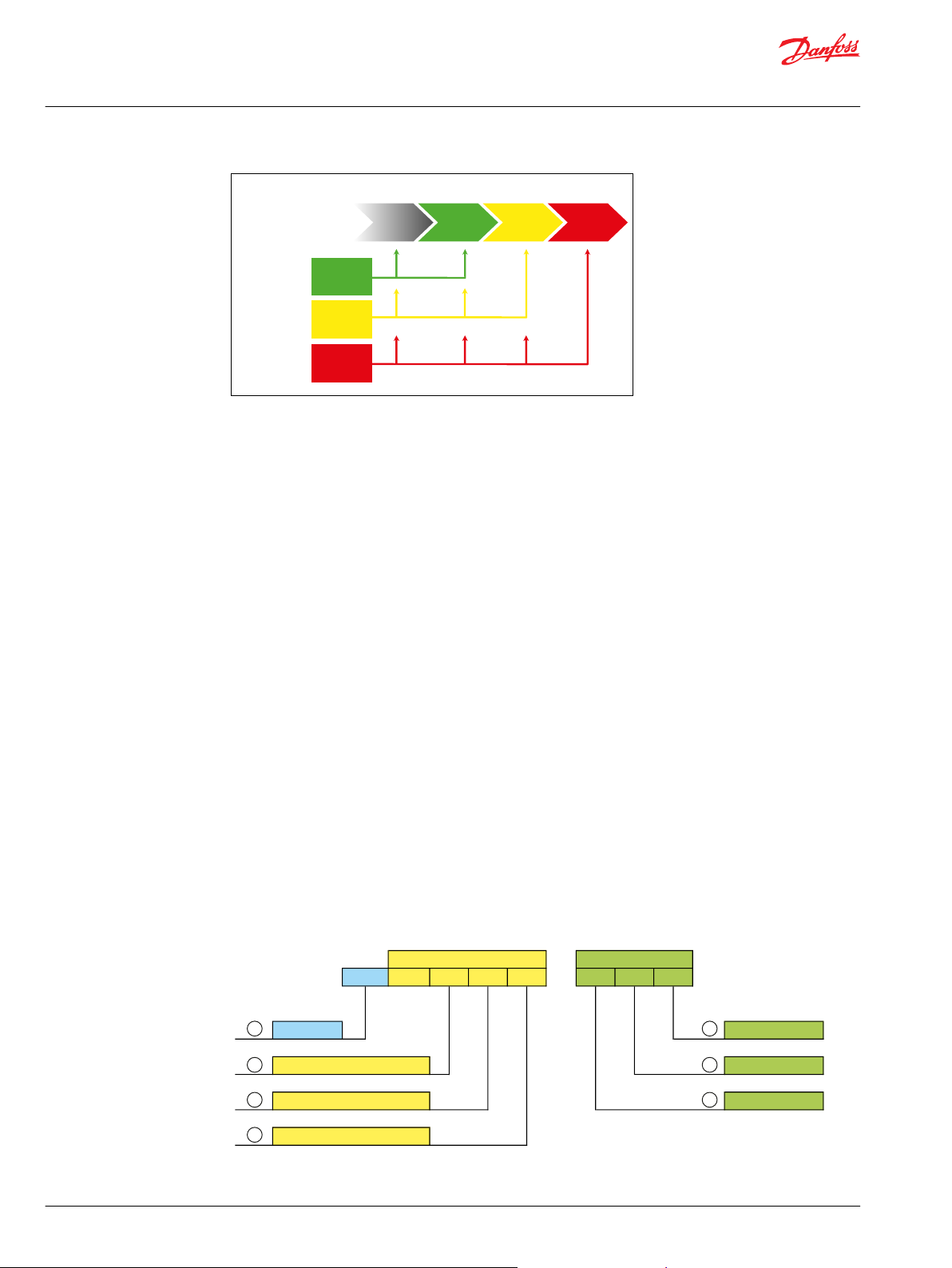
Equipment category and zones
Mechanical components with potential ignition sources e.g. components containing non-conductive
materials or layers or components with hot surface are covered by the ATEX-directive.
Non-mining equipment for potentially explosive atmosphere is classified as:
Equipment Group II – this group comprises three categories according to the level of safety provided:
•
Category 1
•
Category 2
•
Category 3
Category 1 equipment has the highest degree of protection – see the following below.
These products have to fulfil all requirements in the ATEX directive, and have to be marked with the
required “Ex” marking.
Equipment located in zone specified areas must fulfil the following requirements (see also the following
figure):
Category 3 – approved equipment can be installed in hazardous areas zone 2 / 22 and outside zone
•
categorized areas.
Category 2 – approved equipment can be installed in hazardous areas zone 1 / 21, zone 2 / 22 and
•
outside zone categorized areas.
©
Danfoss | April 2022 BC382476944585en-000102 | 5
Category 1 – approved equipment can be installed in hazardous areas zone 0 / 20, zone 1 / 21, zone
•
2 / 22 and outside zone categorized areas.
Page 6
Zone 0Zone 1Zone 2
No requirementsts
Hazards area
Catagory
3
Catagory
2
Catagory
1
ATEX
Directive
Equipment
group II
P301 803
Ex
CE-marking Temperature class
Equipment group Gas Group
Equipment Category Protection type
Nature of atmosphere
Spe cifi c markin g Add itiona l m arki ng
CE II 2 G c II C T4
1
2
3
7
6
5
4
P301 805
Technical Information
ATEX Certified Bent Axis Variable Displacement Motors – H1B 060/080/110/160/210/250
General Information
Contents of marking
The rules for the marking of systems, equipment and components are uniformly defined in the standards
relating to the general technical requirements – EN 13463-1 for mechanical equipment.
A priority for all Ex equipment and protective systems is that the marking should show the areas of their
designated use. Components covered within the scope of the ATEX directive have to be CE-marked, and
marked with the specific “Ex”-sign.
Principle
The marking must indicate the following:
•
The manufacturer who has put the item of equipment on the market
•
Manufacturer’s type identification
•
Year in which the equipment was manufactured
•
A serial number
And further the ignition protection marking
•
Symbol of the equipment group and category (M1 or M2 for group I mining equipment, or 1 or 2 or 3
for Group II non-mining equipment).
Additionally for Group II equipment only:
1. The letter “G” where explosive atmospheres caused by gases, vapours or mists are concerned;
and/or
2. The letter “D” where explosive atmospheres caused by dusts are concerned.
•
Type of ignition protection system.
•
Where appropriate, symbol of explosion group of the equipment.
•
For Group II equipment, the symbol indicating the temperature class or the maximum surface
temperature in °C, or both.
6 | © Danfoss | April 2022 BC382476944585en-000102
Page 7

Technical Information
ATEX Certified Bent Axis Variable Displacement Motors – H1B 060/080/110/160/210/250
General Information
Callout Description
1 CE marking
Specific marking
2 Equipment group I - Mining
II - Non-mining
3 Equipment category 1 (zone 0/20)
2 (zone 1/21)
3 (zone 2/22)
4 Nature of atmosphere G - Gas
D - Dust
Additional marking
5 Protection type fr - Protection by flow restricting enclosure
d - Protection by flameproof enclosure
c - Protection by constructional safety
b - Protection by control of ignition sources
p - Protection by pressurized enclosures
k - Protection by liquid immersion
6 Gas group IIA
IIB
IIC
Equipment without any explosion group maring can be used for
explosive atmosphere of explosive group IIA, IIB and IIC provided
the equipment is not marked for specific atmosphere.
7 Temperature class
T1 to T6
TX; where the maximum surface temperature depends not on
the equipment itself, but mainly on operating conditions (like
heated fluid) the relevant information shall be given in the
instruction for use in order to inform the user about this special
situation.
Marking of Danfoss Bent Axis motors
The Danfoss hydraulic motors are marked as equipment for Group II, category 2 for gas and dust
environment and with ignition protection constructional safety and liquid immersion.
Temperature class/Maximum surface temperature depends on the operating conditions (ambient and
fluid temperature).
ATEX marking
Marking For model code option
CE Ex II 3G Ex h IIA T3 Gc NNA (temperature class T3)
CE Ex II 3G Ex h IIA T4 Gc NNB (temperature class T4)
CE Ex II 3G Ex h IIA T5 Gc NNC (temperature class T5)
1
See Master Model Code and Maximum Surface Temperature for additional information.
1
For detailed information on selecting the appropriate T-codes, please see H1B ATEX User Manual,
BC382476021584.
©
Danfoss | April 2022 BC382476944585en-000102 | 7
Page 8

Made in Germany
Serial No.
N001623456
Model Code
Model No./Ident No.
H1B060-AT-E1ATNA
TBCNGN-NA05NN
035Z00NA
12345678
II 3G Ex h IIA T3 Gc
1
2
3
4
5
6
Technical Information
ATEX Certified Bent Axis Variable Displacement Motors – H1B 060/080/110/160/210/250
General Information
Production place and date of motors
The production location and date of the motors is shown at the first 5 digits of the serial no.
Example: Serial No: N191230941
Five first digits are N1912
N is the manufacturing location (N=Neumünster)
19 is the year (It stands for the last digit in the possible decade).
12 is the week
The last five digits are a consecutive number.
The ATEX certification of the units are done under the scope of:
"Directive 2014/34/EU of the European Parliament and of the Council of 26 February 2014 on the
harmonization of the laws of the Member States relating to equipment and protective systems intended for
use in potentially explosive atmospheres."
With following parameters:
•
Equipment group: II
•
Zone: 2 (gas)
•
Equipment Category: 3G
•
Temperature class: T5...T3
•
Explosion protection group: II A
The Conformity Assessment Procedure has to be executed according to Directive 2014/34/EU, annex VIII,
Modul A: Internal Production Control (see article 13, section 1 (c)).
The EU declaration of conformity has to be prepared and issued with regard to annex X of /1/. The
“Essential Health and Safety Requirements” defined by /1/, annex II, have to be considered.
Example ATEX label - H1B
Example of ATEX label: H1B motor produced in Germany
1. Manufacturer
2. Location of production
3. ATEX code
4. Material number
5. Model code, including unit and displacement
6. Production code
8 | © Danfoss | April 2022 BC382476944585en-000102
Page 9

W
W
Technical Information
ATEX Certified Bent Axis Variable Displacement Motors – H1B 060/080/110/160/210/250
Maximum Surface Temperature
Viscosity and temperature for H1B motors
Features Data
Intermittent
Viscosity
Temperature
1)
Intermittent = Short term t < 3 min per incident.
2)
Cold start = Short term t < 3 min; p ≥ 50 bar; n ≤ 1000 min-1(rpm); please contact Danfoss Power Solutions
especially when the temperature is below -25 °C [-13 °F].
Minimum 7 mm2/sec [49 SUS]
Recommended range 12 - 80 mm2 [66 - 371 SUS]
Maximum (cold start)
Minimum (cold start)
Maximum intermittent
Above maximum surface temperatures are without any deposited dust on the product. The possible
insulation effect of a dust layer on the surface has to be taken into account by the safety margin to the
minimum ignition temperature of the dust concerned. For up to 5 mm [1.97 in] layer thickness the safety
margin is 75°C [167°F]. For further information please see IEC 60079-14.
Warning
1)
2)
2)
1)
5 mm2/sec [42 SUS]
1600 mm2/sec [7416 SUS]
-40°C [-40°F]
115°C [239°F]
The above operating temperatures (ambient and oil) of the motors must be guaranteed by the end user.
Warning
It is compulsory to use oils whose inflammable degree is at least 50K above the maximum surface
temperature of the motors. See also Oil types / Operating fluids.
©
Danfoss | April 2022 BC382476944585en-000102 | 9
Page 10

A B C D E F G H J K L M N P
H1 B
A
Q R
Z
A
N N N
Technical Information
ATEX Certified Bent Axis Variable Displacement Motors – H1B 060/080/110/160/210/250
Master Model Code
H1B ATEX Displacement, Product Version, Port Configuration
Displacement
Code Displacement
060
080
110
160
210
250
A – Product version
A
60 cm³ [3.66 in³]
80 cm³ [4.88 in³]
110 cm³ [6.71 in³]
160 cm³ [9.76 in³]
210 cm³ [12.81 in³]
250 cm³ [15.25 in³]
Revision code
Z – Port configuration
A
Inch, Customer O-ring port sealing according to ISO 11926-1
ATEX Certified Versions of H1B motors
Example:
All ATEX certified H1B motors are equipped with mechanical / hydraulic controls only.
10 | © Danfoss | April 2022 BC382476944585en-000102
Page 11

A B C D E F G H J K L M N P
H1 B
A
Q R
Z
A
N N N
Technical Information
ATEX Certified Bent Axis Variable Displacement Motors – H1B 060/080/110/160/210/250
Master Model Code
H1B control options
B – hydraulic controls
Code Control type PCOR Note
DH
LH
MH
KH
HE
HF
TH
TA
Hydraulic Proportional
Hydraulic 2-position
PCOR
—
—
—
—
External pressure control supply
Default (w/o control pressure) = Maximum
External pressure control supply
Default (w/o control pressure) = Minimum
External pressure control supply
Default (w/o control pressure) = Maximum
External pressure control supply
Default (w/o control pressure) = Minimum
Default (high pressure below PCOR pressure)
©
Danfoss | April 2022 BC382476944585en-000102 | 11
Page 12

A B C D E F G H J K L M N P
H1 B
A
Q R
Z
A
N N N
Technical Information
ATEX Certified Bent Axis Variable Displacement Motors – H1B 060/080/110/160/210/250
Master Model Code
H1B PCOR and BPD options
C – PCOR and BPD
Code PCOR
BA
CA
DA
KA
MA
HA
HB
HE
HF
MH
KH
1
means option is available
1
BPD Details Use with control:
— — — LH
— — — MH
— — TH
— — KH
— — DH
—
Hydraulic
— — HE
— — HF
Hydraulic
Hydraulic
Internal servo pressure supply
De-energized BPD = PCOR active, port not defined
without pilot pressure difference on XA or XB
TH
TH
DH
KH
12 | © Danfoss | April 2022 BC382476944585en-000102
Page 13

A B C D E F G H J K L M N P
H1 B
A
Q R
Z
A
N
N
N
Technical Information
ATEX Certified Bent Axis Variable Displacement Motors – H1B 060/080/110/160/210/250
Master Model Code
H1B threshold setting, orifice options
D – Threshold setting (Hydraulic adjustment)
Code Pressure Code Pressure
A
B
C
D
E
F
G
H
I
J
K
L
N
2 bar [29 psi] M 14 bar [203 psi]
3 bar [43.5 psi] O 15 bar [217.6 psi]
4 bar [58 psi] P 16 bar [232.1 psi]
5 bar [72.5 psi] Q 17 bar [246.6 psi]
6 bar [87 psi] R 18 bar [261 psi]
7 bar [101.5 psi] S 19 bar [275.6 psi]
8 bar [116 psi] T 20 bar [290 psi]
9 bar [130.5 psi] U 22 bar [319 psi]
10 bar [145 psi] V 24 bar [348 psi]
11 bar [159.5 psi] W 26 bar [377.1 psi]
12 bar [174 psi] X 28 bar [406.1 psi]
13 bar [188.5 psi] Y 30 bar [435 psi]
Non applicable All options (except N) to be used for DH, LH, MH, KH
controls.
E – Orifices (M4 and M5)
Code Diameter
A
B
C
Ø1.2 mm [0.047 in]
Ø0.8 mm [0.031 in]
Ø0.6 mm [0.024 in]
©
Danfoss | April 2022 BC382476944585en-000102 | 13
Page 14
A B C D E F G H J K L M N P
H1 B
A
Q R
Z
A
N
N
N
Technical Information
ATEX Certified Bent Axis Variable Displacement Motors – H1B 060/080/110/160/210/250
Master Model Code
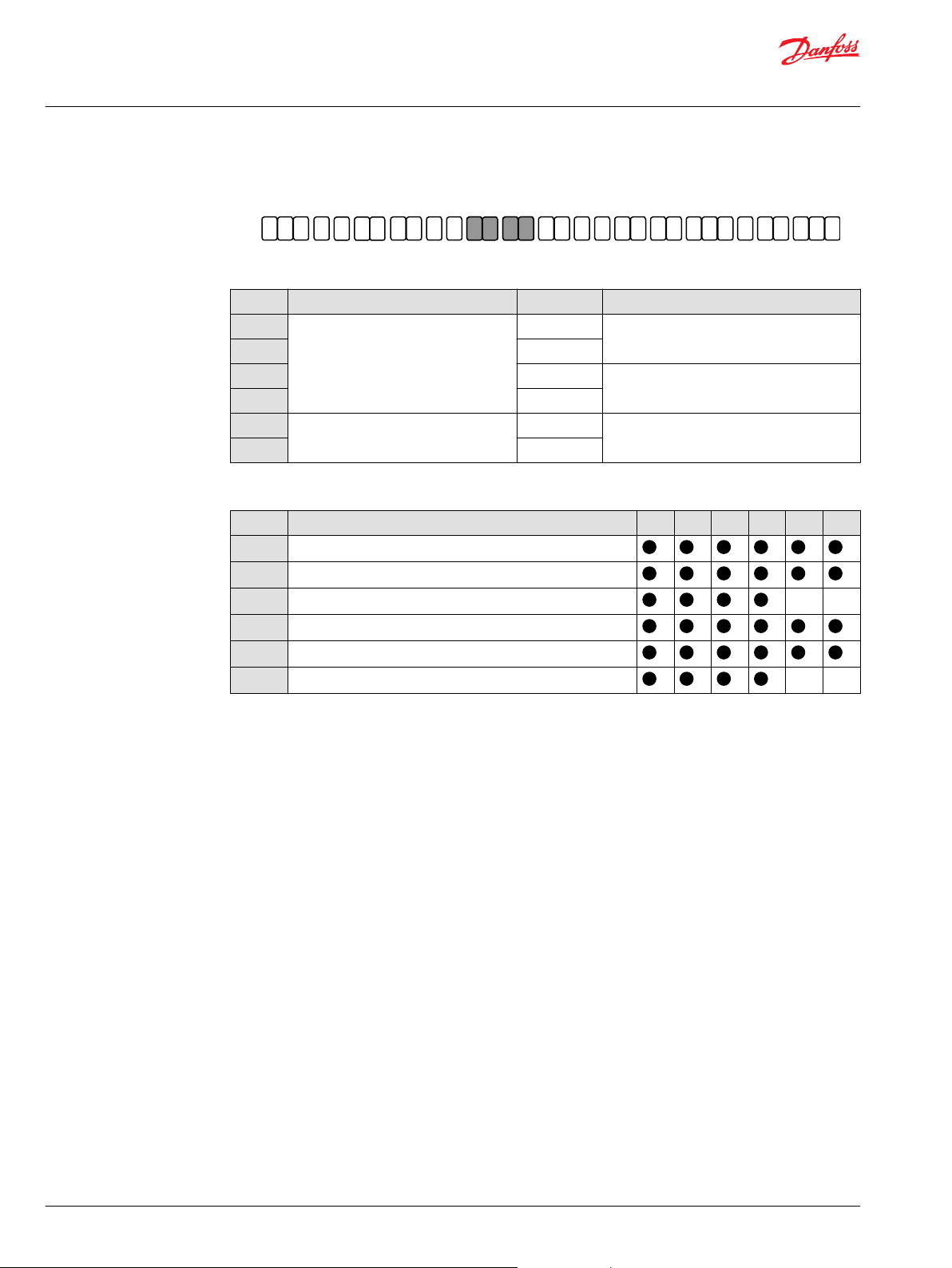
H1B endcap, flange and housing options
F – End-cap (ISO 6162, type 1)
Code Description Port type Compatible controls
PA
PB
RA
RB
TA
TB
Endcap for proportional controls
Endcap for 2-position and PCOR controls
G – Flange and housing
Code Description 060 080 110 160 210 250
VN
DN
CN
VS
DS
CS
SAE flange motor housing (ISO 3019/1), no speed sensor port
DIN flange motor housing (ISO 3019/2), no speed sensor port
Cartridge flange motor housing, no speed sensor port – –
SAE flange motor housing (ISO 3019/1), with speed sensor port
DIN flange motor housing (ISO 3019/2), with speed sensor port
Cartridge flange motor housing, with speed sensor port – –
axial port
side port
axial port
side port
axial port
side port
Use with controls: LH and DH
Use with controls: MH and KH
Use with controls: TA, TH, HE and HF
14 | © Danfoss | April 2022 BC382476944585en-000102
Page 15

A B C D E F G H J K L M N P
H1 B
A
Q R
Z
A
N N N
Technical Information
ATEX Certified Bent Axis Variable Displacement Motors – H1B 060/080/110/160/210/250
Master Model Code
H1B shaft, sensor, loop flushing shuttle system options
H – Shaft options according to speed ring
Code Speed ring Description 060 080 110 160 210 250
AN
AS
BN
BS
CN
CS
DN
DS
EN
ES
FN
FS
GN
GS
HN
HS
JN
JS
KN
KS
LN
LS
No
Yes
No
Yes
No
Yes
No
Yes
No
Yes
No
Yes
No
Yes
No
Yes
No
Yes
No
Yes
No
Yes
14 teeth 12/24 pitch
ANSI 92.1 1970 class 5
21 teeth 16/32 pitch
ANSI 92.1 1970 class 5
23 teeth 16/32 pitch
ANSI 92.1 1970 class 5
27 teeth 16/32 pitch
ANSI 92.1 1970 class 5
13 teeth 8/16 pitch
ANSI 92.1 1970 class 5
15 teeth 8/16 pitch
ANSI 92.1 1970 class 5
W30x2x30x14x9g
DIN 5480
W35x2x30x16x9g
DIN 5480
W40x2x30x18x9g
DIN 5480
W45x2x30x21x9g
DIN 5480
W50x2x30x24x9g
DIN 5480
– – – – –
– –
– – – –
– – –
– – – – –
– – – –
– – – –
– – –
– – – –
– – – –
– – – –
J – Sensor
N
P
No speed sensor
Speed sensor ready (plugged)
K – Loop flushing shuttle system
Code Description 060 080 110 160 210 250
A
B
N
©
Danfoss | April 2022 BC382476944585en-000102 | 15
Standard 6.5 bar [94 psi] shift pressure
12.5 bar [181 psi] shift pressure – –
No loop flushing function
Page 16

A B C D E F G H J K L M N P
H1 B
A
Q R
Z
A
N
N
N
Technical Information
ATEX Certified Bent Axis Variable Displacement Motors – H1B 060/080/110/160/210/250
Master Model Code
H1B loop flushing, special hardware options
L – Loop flushing relief valve (non-adjustable)
Code Flow 060 080 110 160 210 250
05
10
15
20
30
40
50
NN
*
Only in conjunction with loop flushing shuttle system B
5 l/min [1.321 US gal/min], 16 bar [232 psi] cracking pressure – – – –
10 l/min [2.642 US gal/min], 16 bar [232 psi] cracking pressure – – –
15 l/min [3.963 US gal/min], 16 bar [232 psi] cracking pressure – – – – –
20 l/min [5.283 US gal/min], 16 bar [232 psi] cracking pressure – – –
30 l/min [7.925 US gal/min], 16 bar [232 psi] cracking pressure – – –
*
40 l/min [10.567 US gal/min], 16 bar [232 psi] cracking pressure – – –
*
50 l/min [13.209 US gal/min], 16 bar [232 psi] cracking pressure – – –
No loop flushing function
M – Special hardware feature
NN Standard hardware for 2-pos. controls
NP
*
Motors build before March 2018 will have the NN in the Model code and will be updated automatically
Standard hardware for proportional controls
*
16 | © Danfoss | April 2022 BC382476944585en-000102
Page 17

A B C D E F G H J K L M N P
H1 B
A
Q R
Z
A
N
N
N
Technical Information
ATEX Certified Bent Axis Variable Displacement Motors – H1B 060/080/110/160/210/250
Master Model Code
H1B minimum and maximum displacement options
N – Minimum displacement
Code Description Compatible frame
000 or 012 to 040 cm3/rev minimum displacement setting 60cc
000 or 016 to 054 cm3/rev minimum displacement setting 80cc
XXX
MB0 Plug (replaces minimum displacement limiter screw for 0° motors) All
P – Maximum displacement (non adjustable)
Code Displacement Use with controls: 060 080 110 160 210 250
N
A
B
C
E
Z
Q
R
S
T
U
V
000 or 022 to 074 cm3/rev minimum displacement setting 110cc
000 or 032 to 108 cm3/rev minimum displacement setting 160cc
000 or 042 to 142 cm3/rev minimum displacement setting 210cc
000 or 050 to 169 cm3/rev minimum displacement setting 250cc
100 % max. LH, MH, KH and DH
95 % max.
90 % max. – – –
85 % max. – – –
75 % max. – – –
100 % max.
95 % max. displacement
90 % max.
85 % max.
80 % max.
75 % max. –
65 % max.
LH and DH
TH and TA
TH and TA
TH and TA
TH and TA
– – – – –
size
– – –
©
Danfoss | April 2022 BC382476944585en-000102 | 17
Page 18

A B C D E F G H J K L M N P
H1 B
A
Q R
Z
A
N
N
N
Technical Information
ATEX Certified Bent Axis Variable Displacement Motors – H1B 060/080/110/160/210/250
Master Model Code
H1B PCOR pressure, paint and nametag options
Q – PCOR pressure setting
Code Pressure setting Code Pressure setting
00
16
17
18
19
20
21
22
For all controls without PCOR function 23 230 bar [3336 psi]
160 bar [2321 psi] 24 240 bar [3481 psi] – Standard setting
170 bar [2466 psi] 25 250 bar [3626 psi]
180 bar [2611 psi] 26 260 bar [3771 psi]
190 bar [2756 psi] 27 270 bar [3916 psi]
200 bar [2901 psi] 28 280 bar [4061 psi]
210 bar [3046 psi] 29 290 bar [4206 psi]
220 bar [3191 psi] 30 300 bar [4351 psi]
R – Paint and nametag
NNA
NNB
NNC
Factory setting (black paint, ATEX T3 tag, format A w/o filter)
Factory setting (black paint, ATEX T4 tag, format A w/o filter)
Factory setting (black paint, ATEX T5 tag, format A w/o filter)
18 | © Danfoss | April 2022 BC382476944585en-000102
Page 19

W
Technical Information
ATEX Certified Bent Axis Variable Displacement Motors – H1B 060/080/110/160/210/250
Technical Specifications
ATEX technical specifications
The technical specifications in this chapter are supplemental for ATEX systems only. For comprehensive
technical specifications, including maximum pressure rating, maximum flow, etc. please refer to the
standard H1B Technical Information document.
Danfoss does not claim responsibility for the use of the motors in operating conditions not allowed
according to the information shown in this document and the standard H1B Technical Information
document.
Painting or coating can be an electric insulator if a thickness greater than 200 um is applied. The
thickness of the paining of original DPS paint is less than 200 um.
Ambient temperature
Maximum ambient temperature depends on the requested ATEX class needed.
In general the ambient temperature should lie between -40° C [-40° F] and +70° C [158 °F] to ensure that
the shaft seal retains its sealing capacity.
Oil types / Operating fluids
In a hydraulic system the most important task of the oil is to transfer energy. At the same time the oil
must lubricate moving parts in hydraulic components, protect them from corrosion, and transport dirt
particles and heat out of the system. To ensure that hydraulic components operate without problems
and have long operating life it is therefore vital to select the correct oil type with the necessary additives.
Ratings and performance data are based on operating with hydraulic fluids containing oxidation, rust
and foam inhibitors. These fluids must possess good thermal and hydrolytic stability to prevent wear,
erosion and corrosion of motors components.
Warning
It is compulsory to use oils whose inflammable degree is at least 50K above the maximum surface
temperature of the pump. Maximum surface temperature for Group IIG and IID can be found under
Viscosity and temperature for H1B motors on page 9.
Oil temperature
Maximum oil temperature depends on the requested ATEX class needed (in this case T3)..
Under normal operating conditions it is recommended to keep the temperature in the range of 60 °C
[140 °F] to 85 °C [185 °F].
Viscosity
Maintain fluid viscosity within the recommended range for maximum efficiency and bearing life.
Minimum viscosity should only occur during brief occasions of maximum ambient temperature and
severe duty cycle operation. Maximum viscosity should only occur at cold start. Limit speeds until the
system warms up.
Fluid viscosity limits
Conditions mm2/s (cSt) SUS
Minimum 5 42
Continuous 7 49
Maximum 1600 7416
We recommend the use of an oil type having a viscosity of 12 - 80mm2/s [66 - 371 SUS] at the actual
operating temperature.
©
Danfoss | April 2022 BC382476944585en-000102 | 19
Page 20

Danfoss
Power Solutions GmbH & Co. OHG
Krokamp 35
D-24539 Neumünster, Germany
Phone: +49 4321 871 0
Danfoss
Power Solutions ApS
Nordborgvej 81
DK-6430 Nordborg, Denmark
Phone: +45 7488 2222
Danfoss
Power Solutions (US) Company
2800 East 13th Street
Ames, IA 50010, USA
Phone: +1 515 239 6000
Danfoss
Power Solutions Trading
(Shanghai) Co., Ltd.
Building #22, No. 1000 Jin Hai Rd
Jin Qiao, Pudong New District
Shanghai, China 201206
Phone: +86 21 2080 6201
Products we offer:
Hydro-Gear
www.hydro-gear.com
Daikin-Sauer-Danfoss
www.daikin-sauer-danfoss.com
Cartridge valves
•
DCV directional control
•
valves
Electric converters
•
Electric machines
•
Electric motors
•
Gear motors
•
Gear pumps
•
Hydraulic integrated
•
circuits (HICs)
Hydrostatic motors
•
Hydrostatic pumps
•
Orbital motors
•
PLUS+1® controllers
•
PLUS+1® displays
•
PLUS+1® joysticks and
•
pedals
PLUS+1® operator
•
interfaces
PLUS+1® sensors
•
PLUS+1® software
•
PLUS+1® software services,
•
support and training
Position controls and
•
sensors
PVG proportional valves
•
Steering components and
•
systems
Telematics
•
Danfoss Power Solutions is a global manufacturer and supplier of high-quality hydraulic and
electric components. We specialize in providing state-of-the-art technology and solutions
that excel in the harsh operating conditions of the mobile off-highway market as well as the
marine sector. Building on our extensive applications expertise, we work closely with you to
ensure exceptional performance for a broad range of applications. We help you and other
customers around the world speed up system development, reduce costs and bring vehicles
and vessels to market faster.
Danfoss Power Solutions – your strongest partner in mobile hydraulics and mobile
electrification.
Go to www.danfoss.com for further product information.
We offer you expert worldwide support for ensuring the best possible solutions for
outstanding performance. And with an extensive network of Global Service Partners, we also
provide you with comprehensive global service for all of our components.
Local address:
Danfoss can accept no responsibility for possible errors in catalogues, brochures and other printed material. Danfoss reserves the right to alter its products without notice. This also applies to products
already on order provided that such alterations can be made without subsequent changes being necessary in specifications already agreed.
All trademarks in this material are property of the respective companies. Danfoss and the Danfoss logotype are trademarks of Danfoss A/S. All rights reserved.
©
Danfoss | April 2022 BC382476944585en-000102
 Loading...