

Page 1

Service Kit Instructions
P108 602E
P
counterclock
H1 45/53 tandem pump
Charge pump kit
This document provides instructions for installing the charge pump kit.
To complete the assembly you will also need an auxiliary pad kit which includes a
coupling. These items are not included in the charge pump kit.
Refer to H1 45/53 Tandem Pumps Service Manual 520L0928 for complete assembly
instructions
Assembly
1. Lubricate and install seal (K150).
2. Install the housing (K300). Install screws (K350). Refer to the Wrench size and torque
values table for wrench size and torque values.
3. Install alignment pins (K450). Install gasket (K151).
4. Lubricate and assemble the charge pump assembly [coupling, alignment pin
(S500), gerotor (S100), cover (S200), two clips (K205)]. Position the gerotor with the
counterbore towards the bottom.
5. Refer to the following illustration for proper gerotor alignment pin location.
Charge pump alignment pin location
Charge inlet port S
Port ISO 11926-1
1 5/8-12
in location for
wise rotation
Pin location for
clockwise rotation
Charge outlet port F
Port ISO 11926-1
1 1/16-12
6. Install the charge pump assembly into the housing in the clockwise or
counterclockwise orientation.
7. Lubricate and install seal (S300).
8. Install the auxiliary pad kit. Assembly will vary depending on which auxiliary pad is
used. Refer to the Wrench size and torque values table for wrench size and torque
values.
© Danfoss, 2014 AN00000042en-US | 11109777• Rev 0200 • February 2017 1
Page 2
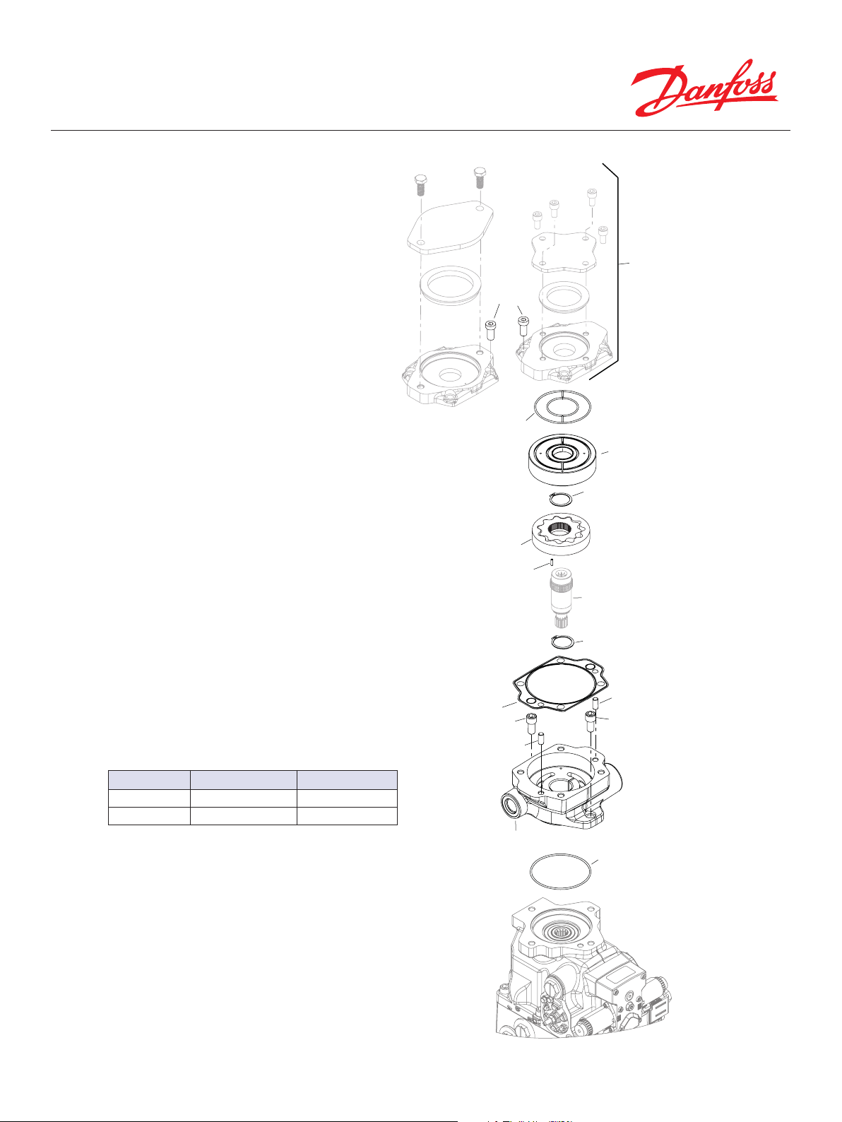
t)
K400 (x4)
S300
S100
S500
Aux pad
kit
S200
K205
Coupling (included in Aux pad ki
K205
K151
K350
K450
K450
K350
Wrench size and torque values
Item Wrench size Torque
K350 10 mm internal hex 76 N•m [56 lbf•ft]
K400 10 mm internal hex 92 N•m [68 lbf•ft]
K300
K150
P108 601E
© Danfoss, 2014 AN00000042en-US | 11109777• Rev 0200 • February 2017 2
 Loading...