

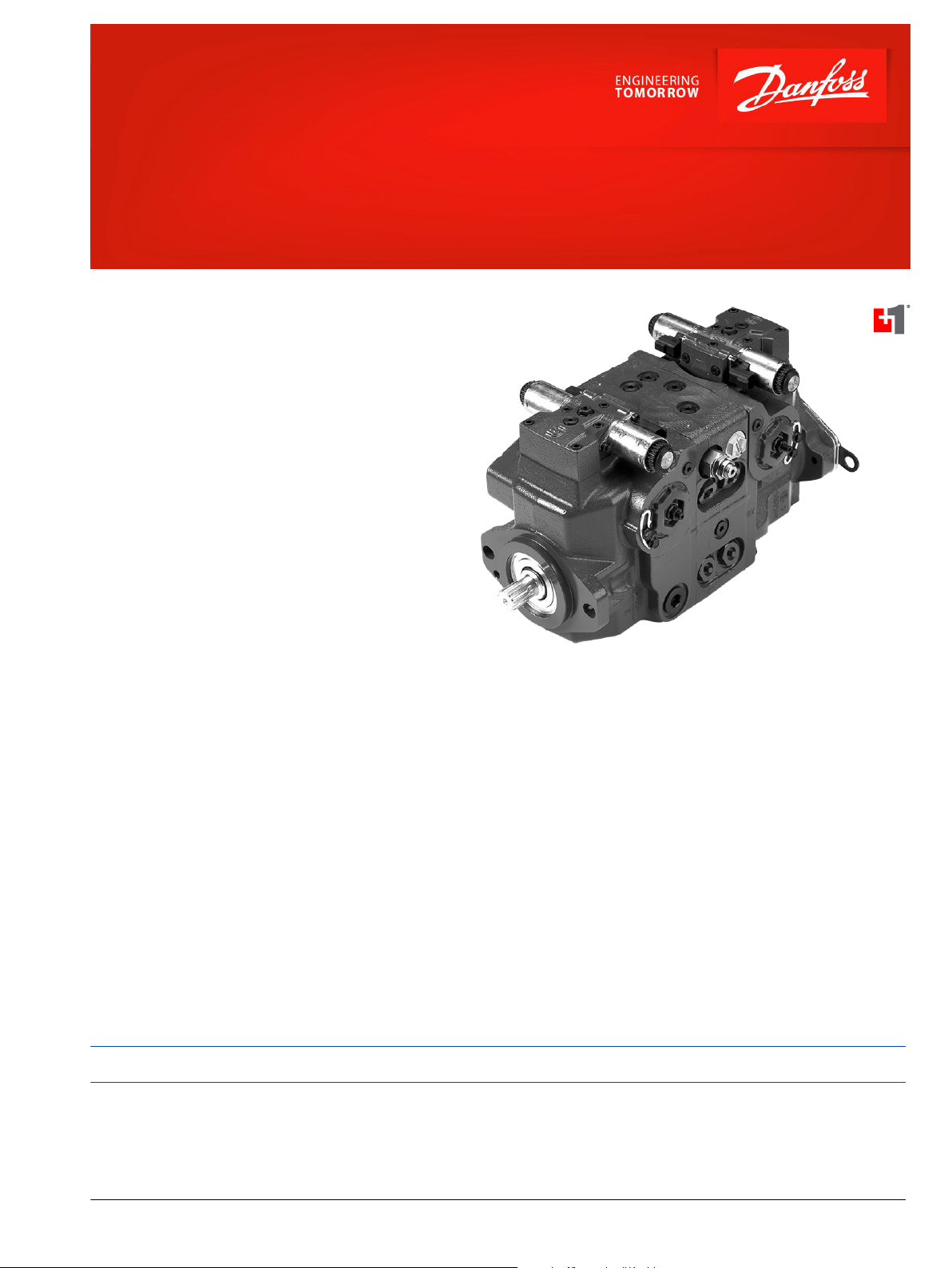
Data Sheet
H1 Axial Piston Tandem Pumps
Size 045/053 cm³
For more than 40 years, Danfoss has been developing
state-of-the-art components and systems for mobile
machinery used in off-highway operations around the
world.
We have become a preferred supplier by offering the
best of what really matters: The hardware inside your
vehicle application.
The H1 range is built around an advanced control and
available in a wide range of displacements. It is
designed for quality and reliability and offers
expanded functionality, greater total efficiency, and
easy installation.
All H1 control and sensor options are PLUS+1
Compliant. PLUS+1® allows you to rapidly develop
and customize electronic machine control. It opens
up the future by combining machine controls and
diagnostics in an integrated operating network.
®
Features
Designed for quality and reliability
•
One design concept
•
Single piece swash plate
•
Integrated auxiliary pad
Installation and packaging benefits
•
Length optimized pump
•
Minimum one clean side
•
Higher corner HP/package size ratio
•
Standardized connector interface
•
High strength mounting flange
Wide range of controls
•
Electro-hydraulic controls:
Comprehensive technical literature is online at www.danfoss.com
Electrical Displacement Control
‒
(EDC)
Forward-Neutral-Reverse (FNR)
‒
Non-Feedback Proportional Electric
‒
(NFPE)
•
Manual Displacement Control (MDC)
•
Hydraulic Displacement Control (HDC)
•
Common control across entire family
Expanded functionality
•
Full compliment of diagnostic ports
including case pressure
•
PLUS+1® Compliant control and sensor
options
•
Control Cut Off (CCO) valve with
integral logic (brake) port
Greater total efficiency
•
Minimized control losses
•
Reduced charge pressure rise rate
between idle and high idle
•
Lower control pressure for less power
consumption
©
Danfoss | December 2021 AI152886483028en-000601 | 1
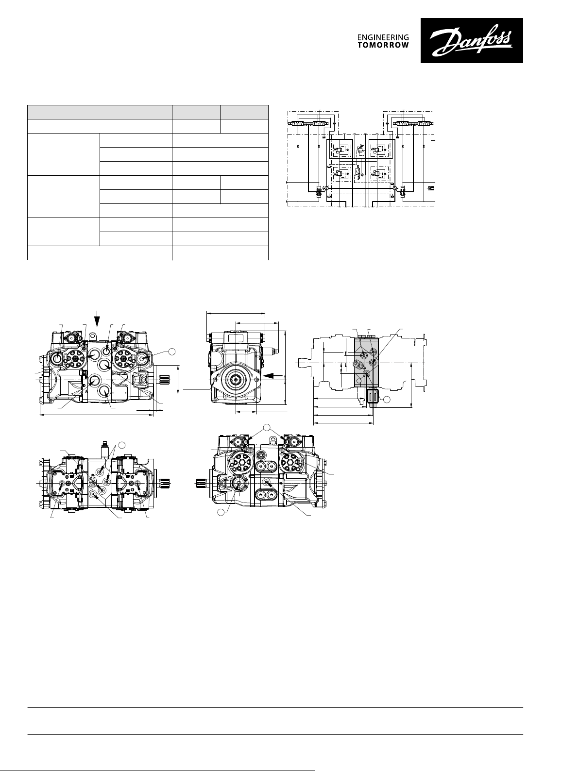
Technical Specifications
C1
C1
C2C2
M14
M14
CW
F00B
F00A
F00B F00A
ABMA
E
C D
MD
MB
M3
L3
MC
M4
M5
M4
M5
PTO
X7
P003 207
L3
A
C
D
B
E M4
M5
M4
M3
M5
P006 063
∅101.6
0
-0.05
9.7
0
-0.5
406 max
209 max
157.7 max
176 max
88.5 max
2x 73 ± 0.25
2x
∅
15.1
+0.25
– 0.13
X7
M14
M14
MB
MB
MC
MC
216.32
214.32
191.82
183.32
25.3
37.5
167.2 max.
39.0
CCO
CCW
CW
Y
X
Y
X
4
2
1
3
3
Frame size Size 045 Size 053
Displacement cm3 [in3] 45.0 [2.75] 53.8 [3.28]
Input speed
min-1 (rpm)
Minimum 500
Rated 3400
Maximum 3500
System pressure
bar [psi]
Max. working
Maximum 450 [6525] 400 [5800]
*
420 [6090] 380 [5510]
Min. low loop 10 [150]
Case pressure
bar [psi]
Rated 3.0 [40]
Maximum 5.0 [75]
Weight (without PTO and filter), kg [lb] 65.0 [143.0]
*
Applied pressures above maximum working pressure requires Danfoss
application approval.
Dimensions
Schematic
Legend:
A/B/C/D – System ports, 1 5/16-12; Ø48.5
MA/MB/MC/MD – System gauge ports, 9/16-18; Ø28
M3 – Charge gauge port, 9/16-18; Ø28
M4, M5 – Servo gauge ports, 7/16-20; Ø24.5
M14 – Case gauge port, 5/16 -24; Ø21.0
E – Charge inlet port, 7/16-20; Ø36
L3 – Case drain port, 1 1/16-12 Ø48.5
All ports per ISO 11926-1, max. clearance dia for fitting.
Danfoss can accept no responsibility for possible errors in catalogues, brochures and other printed material. Danfoss reserves the right to alter its products without notice. This also applies to products
already on order provided that such alterations can be made without subsequent changes being necessary in specifications already agreed.
All trademarks in this material are property of the respective companies. Danfoss and the Danfoss logotype are trademarks of Danfoss A/S. All rights reserved.
2 | © Danfoss | December 2021 AI152886483028en-000601
CCO – Control Cut Off valve option
X7 – Brake gauge port 9/16 -18 Ø28.0
1 – Case pressure port, 1 1/16-12 Ø41.0
2 – Case pressure port, 1 1/16-12 Ø48.5
3 – Charge constr. port, 9/16-18; Ø28
4 – Connector DEUTSCH DT04-2P
 Loading...