

Page 1
Basic Information
H1 Axial Piston Pumps
Single and Tandem
www.danfoss.com
Page 2

Basic Information
H1 Axial Piston Pumps, Single and Tandem
Revision history Table of revisions
Date Changed Rev
December 2021 Added Hydraulic Displacement Control section 1001
January 2021 Changed document number from 'BC00000057' to 'BC152886483968' and added
280cc information
November 2019 Speed sensor, Integral Charge Pressure Filtration data changes. 0703
April 2019 CCO topic update. 0702
May 2018 Angle sensor for EDC controls added. 0701
April 2017 NFPE and AC controls added. 0602
May 2016 Updated to Engineering Tomorrow design. 0601
Nov 2010-Nov 2015 Various changes. BA-0501
Jul 2009 First edition. AA
0901
2 | © Danfoss | December 2021 BC152886483968en-001001
Page 3

Basic Information
H1 Axial Piston Pumps, Single and Tandem
Contents
Danfoss hydrostatic product family
A word about the organization of this manual..................................................................................................................... 5
General description of H1 family hydrostatic pumps..........................................................................................................5
Overview of H1 Pumps Technical Specifications..................................................................................................................6
H1 Pumps Literature Reference...................................................................................................................................................7
Operation
Pressure Limiter Valves...................................................................................................................................................................8
High Pressure Relief Valve (HPRV) and Charge Check Valve.............................................................................................8
Bypass function.................................................................................................................................................................................9
System Schematic for Single Pump...........................................................................................................................................9
System Schematic for Tandem Pumps...................................................................................................................................10
Charge Pressure Relief Valve (CPRV)....................................................................................................................................... 10
Electrical Displacement Control (EDC)................................................................................................................................... 11
EDC Operation...........................................................................................................................................................................11
Manual Displacement Control (MDC) ....................................................................................................................................12
MDC operation.......................................................................................................................................................................... 12
Neutral start switch (NSS)...................................................................................................................................................... 13
Hydraulic Displacement Control (HDC)................................................................................................................................. 14
HDC principle.............................................................................................................................................................................14
Automotive Control (AC) ............................................................................................................................................................15
Automotive Control connection diagram.......................................................................................................................16
Forward-Neutral-Reverse (FNR) electric control.................................................................................................................17
Non feedback proportional electric control (NFPE).......................................................................................................... 17
Fan Drive Control (FDC)...............................................................................................................................................................18
Control Signal Requirements, FDC ....................................................................................................................................18
Manual Override (MOR)............................................................................................................................................................... 20
Swashplate angle sensor for EDC controls........................................................................................................................... 21
Swash Plate Angle Sensor for NFPE and AC2 Controls.....................................................................................................22
Control Cut Off Valve (CCO)....................................................................................................................................................... 23
Brake gauge port with MDC................................................................................................................................................. 23
Displacement Limiter................................................................................................................................................................... 24
Life Time............................................................................................................................................................................................24
Speed and Temperature Sensor...............................................................................................................................................25
Description..................................................................................................................................................................................25
Theory of Operation................................................................................................................................................................ 25
Target Ring..................................................................................................................................................................................25
Mating Connectors...................................................................................................................................................................25
Speed sensor 4.5 – 8 V technical data...............................................................................................................................26
Temperature sensor data.......................................................................................................................................................26
Operating Parameters
Input Speed......................................................................................................................................................................................28
System Pressure..............................................................................................................................................................................28
Servo Pressure.................................................................................................................................................................................29
Charge Pressure..............................................................................................................................................................................29
Charge Pump Inlet Pressure.......................................................................................................................................................29
Case Pressure...................................................................................................................................................................................29
External Shaft Seal Pressure....................................................................................................................................................... 30
Temperature.................................................................................................................................................................................... 30
Viscosity.............................................................................................................................................................................................30
System design parameters
Fluid Specification......................................................................................................................................................................... 31
Fluid selection............................................................................................................................................................................31
Filtration System.............................................................................................................................................................................32
Suction Filtration............................................................................................................................................................................33
Charge pressure filtration (full charge pump flow)........................................................................................................... 33
Remote Charge Pressure Filtration.................................................................................................................................... 34
Integral Charge Pressure Filtration.....................................................................................................................................35
H1P Filters Ordering Numbers.............................................................................................................................................36
©
Danfoss | December 2021 BC152886483968en-001001 | 3
Page 4

Basic Information
H1 Axial Piston Pumps, Single and Tandem
Contents
Filter Bypass Characteristic....................................................................................................................................................37
Bypass Sensor Clearance........................................................................................................................................................37
Reservoir............................................................................................................................................................................................38
Case drain......................................................................................................................................................................................... 38
Charge pump...................................................................................................................................................................................39
Bearing loads and life .................................................................................................................................................................. 40
Mounting flange loads.................................................................................................................................................................41
Shaft Torque for Splined Shafts................................................................................................................................................ 42
Shaft Torque for Tapered Shafts...............................................................................................................................................42
Shaft availability and torque ratings.......................................................................................................................................43
Minimizing System Noise............................................................................................................................................................44
Determination of Nominal Pump Sizes..................................................................................................................................45
4 | © Danfoss | December 2021 BC152886483968en-001001
Page 5

Basic Information
H1 Axial Piston Pumps, Single and Tandem
Danfoss hydrostatic product family
A word about the organization of this manual
General information covering all displacements of the H1 range is given in the beginning of this manual.
This includes definitions of operating parameters and system design considerations.
The next sections in the book detail the specific operating limitations for each frame and give a full
breakdown of available displacements, features and options.
General description of H1 family hydrostatic pumps
The H1 family of closed circuit variable displacement axial piston pumps is designed for use with all
existing Danfoss hydraulic motors for the control and transfer of hydraulic power. The H1 axial piston
variable displacement pumps are of cradle swash-plate design and are intended for closed circuit
applications.
Flow direction is reversed by tilting the swash-plate to the opposite side of the neutral (zero
displacement) position. The flow rate is proportional to the pump input speed and displacement. The
latter is infinitely adjustable between zero and maximum displacement.
H1 pumps can be used together in combination with other Danfoss pumps and motors in the overall
hydraulic system.
Danfoss hydrostatic products are designed with 15 different displacements (cm³ [in³]):
•
045 053 060 068 069 078 089 100 115 130 147 165 210 250 280
45.0
[2.75]
53.8
[3.28]
60.4
[3.69]
68.0
[4.15]
69.0
[4.22]
Danfoss hydrostatic products are designed with many different pressure, load-life and control
•
78.0
[4.76]
89.2
[5.44]
101.7
[6.21]
115.8
[7.07]
130.8
[7.98]
147.0
[8.97]
165.0
[10.07]
211.5
[12.91]
251.7
[15.36]
280.2
[17.10]
capabilities:
Electric Displacement Control (EDC)
‒
Forward-Neutral-Reverse control (FNR)
‒
Non-Feedback Proportional Electric control (NFPE)
‒
Automotive Control (AC)
‒
Fan Drive Control (FDC)
‒
Manual Displacement Control (MDC)
‒
Hydraulic Displacement Control (HDC)
‒
Control-Cut-Off valve (CCO)
‒
High power density where all units utilize an integral electro-hydraulic servo piston assembly that
•
controls the rate (speed) and direction of the hydraulic flow.
Compatible with the Danfoss family of PLUS+1® micro-controllers for easy Plug-and-Perform
•
installation.
More compact and lightweight
•
Improved reliability and performance
•
Go to the Danfoss website or applicable product catalog to choose the components that are right for
your complete closed circuit hydraulic system.
©
Danfoss | December 2021 BC152886483968en-001001 | 5
Page 6

Basic Information
H1 Axial Piston Pumps, Single and Tandem
Danfoss hydrostatic product family
Overview of H1 Pumps Technical Specifications
The table shows the available range of H1 pumps as of this printing, with their respective speed, pressure,
weight and mounting flange.
Feature 045 053 060 068 069 078 089 100 115 130 147 165 210 250 280
3
45.0
53.8
60.4
68.0
69.2
78.1
89.2
101.7
115.2
130.0
147.2
165.1
211.5
Displacement cm
[in3]
Rated speed, min
(rpm)
Max. speed, min
(rpm)
Max. working
pressure, bar [psi]
Max pressure, bar
[psi]
Weight dry, kg [lb]
(without PTO/filter)
Mounting flange
1)
Applied pressures above maximum working pressure requires Danfoss application approval.
[2.75]
[3.28]
[3.69]
[4.15]
[4.22]
[4.77]
[5.44]
[6.21]
-1
3400 3400 3500 3500 3500 3500 3300 3300 3200 3200 3000 3000 2600 2600 2600
-1
3500 3500 4000 4000 4000 4000 3800 3800 3400 3400 3100 3100 2800 2800 2800
420
380
420
380
450
450
450
1)
[6092]
[5511]
[6092]
[5511]
[6527]
[6527]
450
400
450
400
480
[6527]
[5802]
[6527]
[5802]
single: 41 [90]
tandem: 65
[143]
SAE B, 2-bolt SAE C, 4-bolt SAE D, 4-bolt SAE E, 4-bolt
single: 50 [110]
tandem: 96.2
[212]
480
[6962]
[6962]
56
[123]56[123]62[137]62[137]83[187]83[187]96[211]96[211]
[6527]
480
[6962]
450
[6527]
480
[6962]
[7.03]
450
[6527]
480
[6962]
[7.93]
450
[6527]
480
[6962]
[8.98]
450
[6527]
480
[6962]
[10.08]
450
[6527]
480
[6962]
[12.91]
450
[6527]
480
[6962]
163
[360]
251.7
[15.36]
450
[6527]
480
[6962]
163
[360]
280.2
[17]
420
[6092]
450
[6527]
163
[360]
6 | © Danfoss | December 2021 BC152886483968en-001001
Page 7

Basic Information
H1 Axial Piston Pumps, Single and Tandem
Danfoss hydrostatic product family
H1 Pumps Literature Reference
Available literature for H1 Pumps
Title Literature Type Number
H1 Axial Piston Pumps, Single and Tandem Product Line Overview AM152886484212
H1 Axial Piston Pumps, Single and Tandem Basic Information BC152886483968
H1T 045/053/060/068 Axial Piston Tandem Pumps Technical Information BC152886483958
H1P 045/053 Axial Piston Single Pumps Technical Information BC152886483105
H1P 060/068 Axial Piston Single Pumps Technical Information BC152886483241
H1P 069/078 Axial Piston Single Pumps Technical Information BC152886483133
H1P 089/100 Axial Piston Single Pumps Technical Information BC152886482765
H1P 115/130 Axial Piston Single Pumps Technical Information BC152886483053
H1P 147/165 Axial Piston Single Pumps Technical Information BC152886482989
H1P 210/25/280 Axial Piston Single Pumps Technical Information BC152986484463
H1P 045/053/060/068 Axial Piston Single Pumps Service Manual AX152886481964
H1T 045/053/060/068 Axial Piston Tandem Pumps Service Manual AX152886481761
H1P 069–280 Axial Piston Single Pumps Service Manual AX152886482551
Data sheets for all pump sizes are available.
Further available literature
Title Literature Type Number
H1 Pump Electrical Displacement Control (EDC) Electrical Installation BC152886483648
H1 Pump 3-position Electric Control (FNR) Electrical Installation BC152886483708
H1 Pump Non-Feedback Prop. Electric Control (NFPE) Electrical Installation BC152886483538
H1 Pump Automotive Control (AC) Technical Information BC152986482596
H1 Automotive on PLUS+1 for MC024 Technical Information BC152986484456
Speed and Temperature Sensor Technical Information BC152886482203
Pressure Sensor Technical Information BC152886484429
External Remote Charge Pressure Filter Technical Information BC152886484487
Design Guideline for Hydraulic Fluid Cleanliness Technical Information BC152886482150
Hydraulic Fluids and Lubricants Technical Information BC152886484524
©
Danfoss | December 2021 BC152886483968en-001001 | 7
Page 8

Basic Information
H1 Axial Piston Pumps, Single and Tandem
Operation
Pressure Limiter Valves
Pressure limiter valves provide system pressure protection by compensating the pump swash plate
position when the set pressure of the valve is reached. A pressure limiter is a non-dissipative (non heat
generating) pressure regulating system.
Each side of the transmission loop has a dedicated pressure limiter valve that is set independently. A
pump configured with pressure limiter must have pressure limiters on both sides of the system pressure
loop. The pump order code allows for different pressure settings to be used at each system port.
The pressure limiter setting is the maximum differential pressure between the high and low loops. When
the pressure limiter setting is reached, the valve ports oil to the low-pressure side of the servo piston. The
change in servo differential pressure rapidly reduces pump displacement. Fluid flow from the valve
continues until the resulting drop in pump displacement causes system pressure to fall below the
pressure limiter setting.
An active pressure limiter destrokes a pump to near neutral when the load is in a stalled condition. The
pump swash-plate moves in either direction necessary to regulate the system pressure, including into
stroke (overrunning) or over-center (winch payout).
The pressure limiter is optional on H1 pumps (except H1T 045/053 tandem pumps).
High Pressure Relief Valve (HPRV) and Charge Check Valve
All H1 pumps have a combination high pressure relief and charge check valve. The high pressure relief
function is a dissipative (heat generating) pressure control valve for the purpose of limiting excessive
system pressures. The charge check function replenishes the low pressure side of the working loop with
charge oil.
Each side of the transmission loop has a dedicated HPRV valve that is non-adjustable with a factory set
pressure. When system pressure exceeds the factory setting of the valve, oil is passed from the high
pressure system loop, into the charge gallery, and into the low pressure system loop via the charge
check.
The pump may have different pressure settings to be used at each system port. When an HPRV valve is
used in conjunction with a pressure limiter, the HPRV valve is always factory set above the setting of the
pressure limiter. The system pressure shown in the order code for pumps with only HPRV is the HPRV
setting.
The system pressure shown in the order code for pumps with pressure limiter and HPRV is a reflection of
the pressure limiter setting:
HPRVs are set at low flow condition. Any application or operating condition which leads to elevated HPRV
flow will cause a pressure rise with flow above the valve setting. Consult factory for application review.
Excessive operation of the HPRV will generate heat in the closed loop and may cause damage to the
internal components of the pump.
8 | © Danfoss | December 2021 BC152886483968en-001001
Page 9
A
B
MA
S
M3
C2
C1
M4
M5
MBL4
L2
M6 1 2
R2
R1
M14
F00B F00A
CW
P003 418E
Basic Information
H1 Axial Piston Pumps, Single and Tandem
Operation
Bypass function
The bypass function allows a machine or load to be moved without rotating the pump shaft or prime
mover. The single pump HPRV valve also provides a loop bypass function when each of the two HPRV hex
plugs are mechanically backed out three full turns.
Engaging the bypass function mechanically connects both A & B sides of the working loop to the
common charge gallery.
Possible damage to hydromotor(s).
Excessive speeds and extended load/vehicle movement must be avoided. The load or vehicle should be
moved not more than 20% of maximum speed and for a duration not exceeding 3 minutes. When the
bypass function is no longer needed, care should be taken to re-seat the HPRV hex plugs to the normal
operating position.
Bypass function not available for tandem pumps.
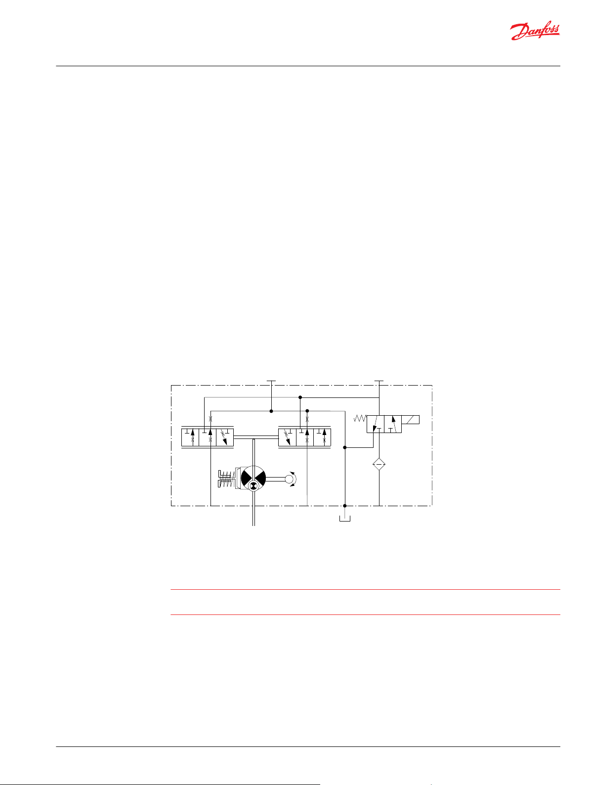
System Schematic for Single Pump
The schematic below shows the function of an H1P axial piston variable displacement pump with electric
displacement control (EDC).
©
Danfoss | December 2021 BC152886483968en-001001 | 9
Page 10
C1
C1
C2C2
M14
M14
CW
F00B
F00A
F00B F00A
A
B
MA
E
C D
MD
MB
M3
L3
MC
M4
M5
M4
M5
PTO
X7
P003 207E
Basic Information
H1 Axial Piston Pumps, Single and Tandem
Operation
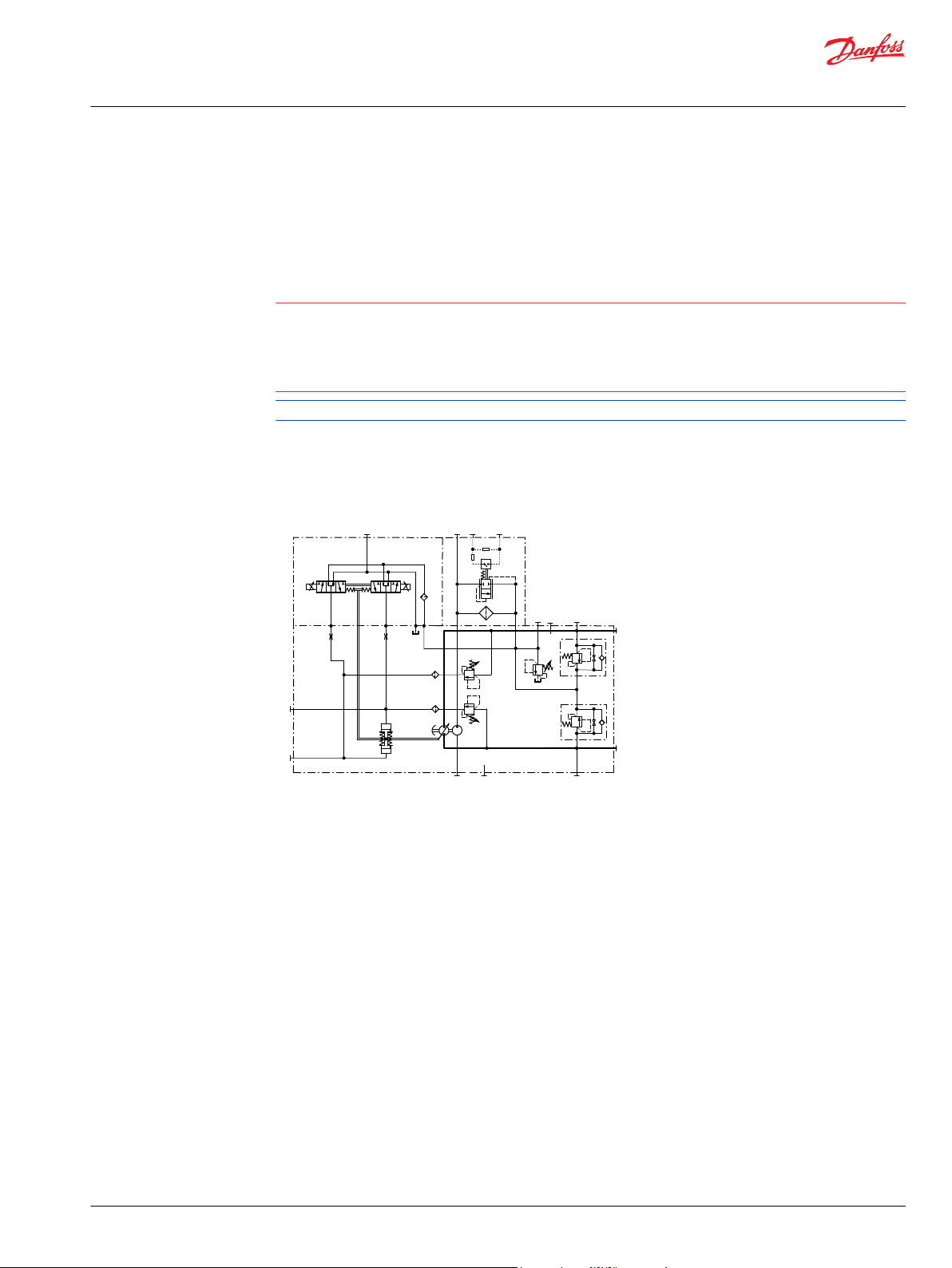
System Schematic for Tandem Pumps
The schematic below shows the function of H1T axial piston variable displacement tandem pumps with
electric displacement control (EDC).
System schematic, tandem pumps
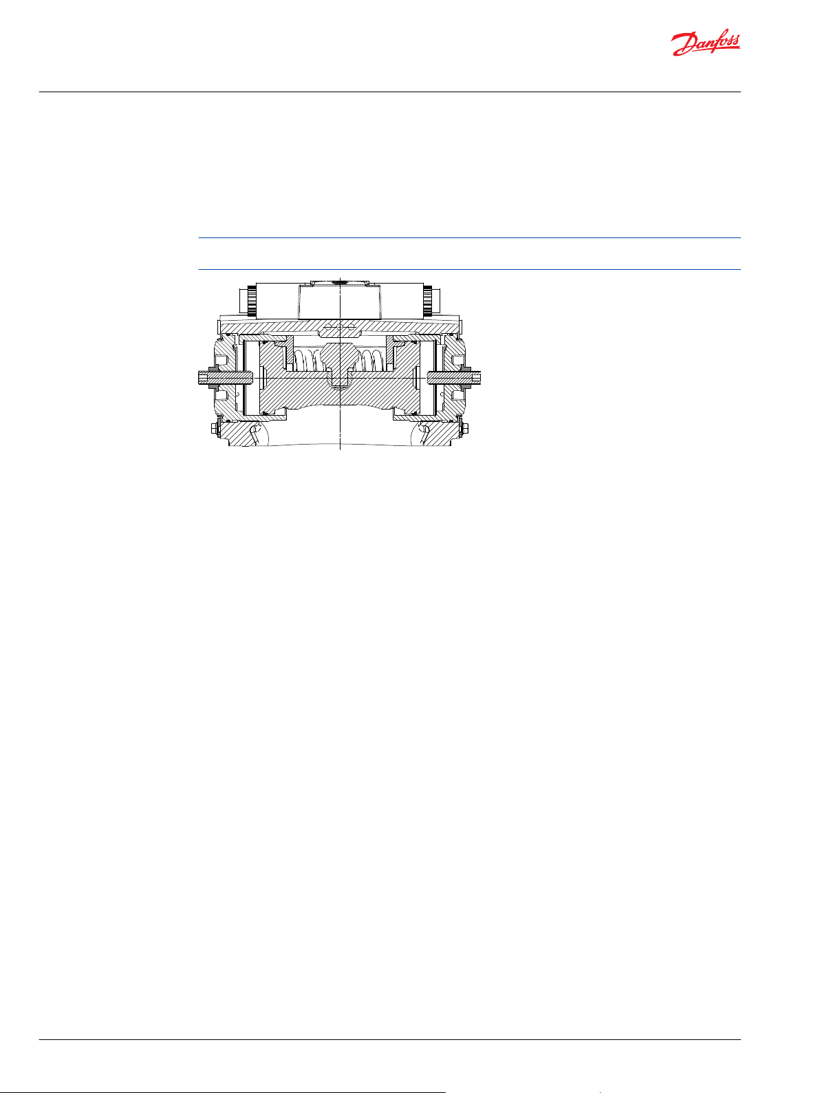
Charge Pressure Relief Valve (CPRV)
The charge pressure relief valve is a direct acting poppet valve that opens and discharges fluid to the
pump case when pressure exceeds a designated level. The charge pressure relief valve maintains charge
pressure at a designated level above case pressure.
This level is nominally set with the pump running at 1800 min-1(rpm), and with a fluid viscosity of 32
mm²/s [150 SUS]. In forward or reverse, charge pressure will be slightly lower than in neutral position. The
model code of the pump specifies the charge pressure relief valve setting. Typical charge pressure
increase from 1.2-1.5 bar per 10 l/min [17.4-21.8 psi per 2.64 US gal/min]. For external charge flow the
CPRV is set according to the table below:
CPRV flow setting for external charge supply
Tandem 045/053 Single 045/053 Single 060—165 Single 210/250/280
30 l/min [7.9 US gal/min] 15 l/min [3.9 US gal/min] 22.7 l/min [6.0 US gal/min] 40.0 l/min [10.6 US gal/min]
Charge pressure relief valve
10 | © Danfoss | December 2021 BC152886483968en-001001
Page 11
P003 191
Feedback from
Swash plate
PTF00B
M14
C1 C2
F00A
P003 478E
Basic Information
H1 Axial Piston Pumps, Single and Tandem
Operation
Electrical Displacement Control (EDC)
An EDC is a displacement (flow) control. Pump swash plate position is proportional to the input
command and therefore vehicle or load speed (excluding influence of efficiency), is dependent only on
the prime mover speed or motor displacement.
The Electrical Displacement Control (EDC) consists of a pair of proportional solenoids on each side of a
three-position, four-way porting spool. The proportional solenoid applies a force input to the spool,
which ports hydraulic pressure to either side of a double acting servo piston. Differential pressure across
the servo piston rotates the swash plate, changing the pump‘s displacement from full displacement in
one direction to full displacement in the opposite direction.
A serviceable 170 μm screen is located in the supply line immediately before the control porting spool.
Under some circumstances, such as contamination, the control spool could stick and cause the pump to
stay at some displacement.
Electrical Displacement Control
EDC schematic, feedback from swash plate
EDC Operation
H1 EDC’s are current driven controls requiring a Pulse Width Modulated (PWM) signal. Pulse width
modulation allows more precise control of current to the solenoids.
The PWM signal causes the solenoid pin to push against the porting spool, which pressurizes one end of
the servo piston, while draining the other. Pressure differential across the servo piston moves the
swashplate.
A swashplate feedback link, opposing control links, and a linear spring provide swashplate position force
feedback to the solenoid. The control system reaches equilibrium when the position of the swashplate
spring feedback force exactly balances the input command solenoid force from the operator. As
hydraulic pressures in the operating loop change with load, the control assembly and servo/swashplate
system work constantly to maintain the commanded position of the swashplate.
The EDC incorporates a positive neutral deadband as a result of the control spool porting, preloads from
the servo piston assembly, and the linear control spring. Once the neutral threshold current is reached,
the swashplate is positioned directly proportional to the control current. To minimize the effect of the
control neutral deadband, we recommend the transmission controller or operator input device
incorporate a jump up current to offset a portion of the neutral deadband.
The neutral position of the control spool does provide a positive preload pressure to each end of the
servo piston assembly.
When the control input signal is either lost or removed, or if there is a loss of charge pressure, the springloaded servo piston will automatically return the pump to the neutral position.
©
Danfoss | December 2021 BC152886483968en-001001 | 11
Page 12
"0"
Lever rotation
"A"
Displacement
100 %
a
-a
100 %
"B"
-b
-d
b
c
d
-c
P301 752
Basic Information
H1 Axial Piston Pumps, Single and Tandem
Operation
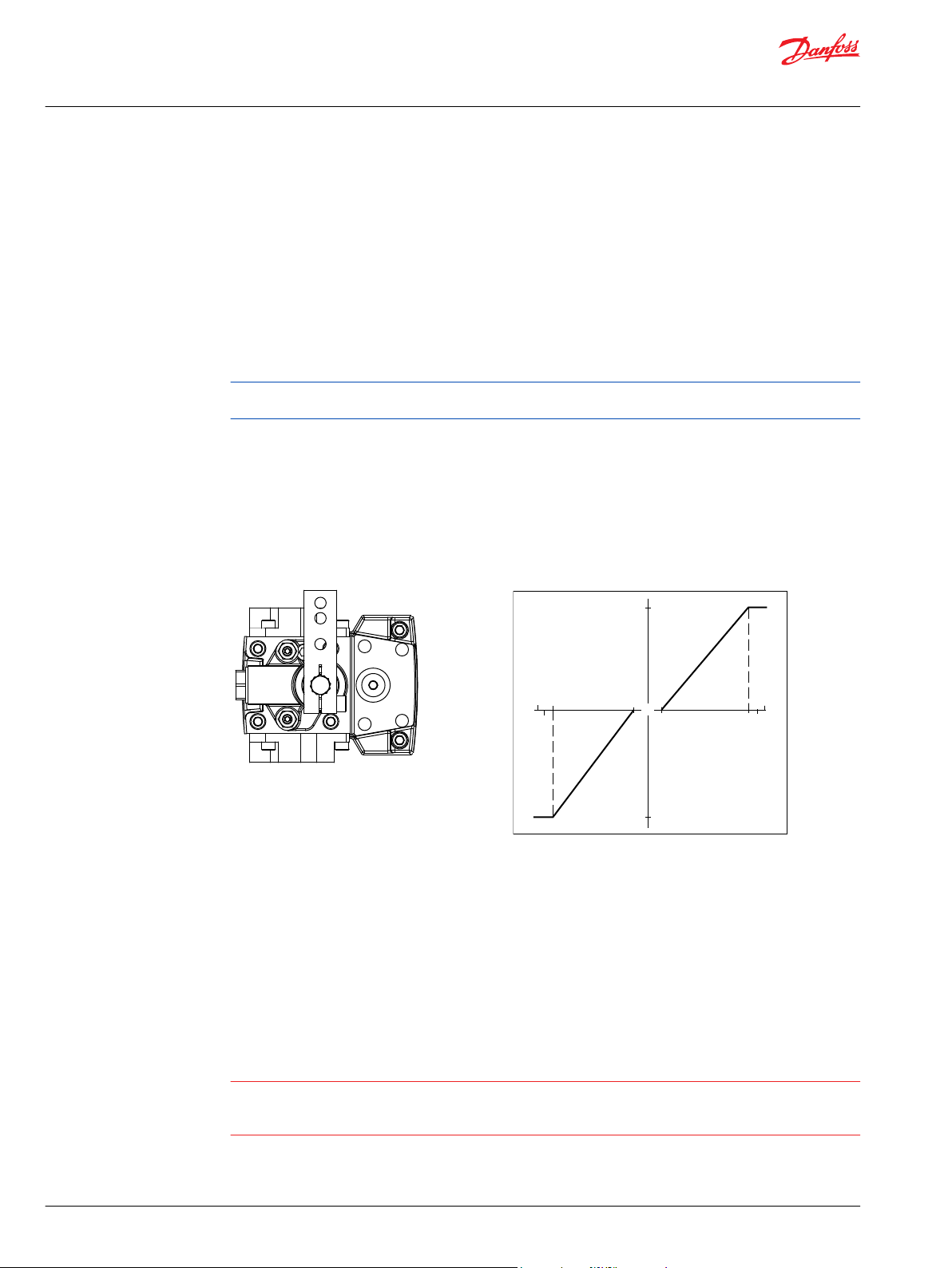
Manual Displacement Control (MDC)
A Manual proportional Displacement Control (MDC) consists of a handle on top of a rotary input shaft.
The shaft provides an eccentric connection to a feedback link. This link is connected on its one end with a
porting spool. On its other end the link is connected the pumps swashplate.
This design provides a travel feedback without spring. When turning the shaft the spool moves thus
providing hydraulic pressure to either side of a double acting servo piston of the pump.
Differential pressure across the servo piston rotates the swash plate, changing the pump’s displacement.
Simultaneously the swashplate movement is fed back to the control spool providing proportionality
between shaft rotation on the control and swash-plate rotation. The MDC changes the pump
displacement between no flow and full flow into opposite directions.
Under some circumstances, such as contamination, the control spool could stick and cause the pump to
stay at some displacement.
For the MDC with CCO option the brake port (X7) provides charge pressure when the coil is energized to
activate static function such as a brake release. The X7 port must not be used for any continuous oil
consumption.
The MDC is sealed by means of a static O-ring between the actuation system and the control block. Its
shaft is sealed by means of a special O-ring which is applied for low friction. The special O-ring is
protected from dust, water and aggressive liquids or gases by means of a special lip seal.
Manual Displacement Control Pump displacement vs. control lever rotation
Deadband on B side: a = 3° ±1°
Maximum pump stroke: b = 30° +2/-1°
Required customer end stop: c = 36° ±3°
Internal end stop: d = 40°
MDC operation
The MDC provides a mechanical dead-band required to overcome the tolerances in the mechanical
actuation. The MDC contains an internal end stop to prevent turning the handle into any inappropriate
position.
The MDC provides a permanent restoring moment appropriate for turning the MDC input shaft back to
neutral position only. This is required to take the backlash out of the mechanical connections between
the Bowden cable and the control.
High case pressure may cause excessive wear and the NSS to indicate that the control is not in neutral
position. In addition, if the case pressure exceeds 5 bar there is a risk of an insufficient restoring moment.
The MDC is designed for a maximum case pressure of 5 bar and a rated case pressure of 3 bar.
12 | © Danfoss | December 2021 BC152886483968en-001001
Page 13
C
P005 702
M14
M5
M4
M3
Basic Information
H1 Axial Piston Pumps, Single and Tandem
Operation
Customers must install some support to limit the setting range of their Bowden cable to avoid an
•
overload of the MDC.
Customers can apply their own handle design but they must care about a robust clamping
•
connection between their handle and the control shaft and avoid overload of the shaft.
Customers can connect two MDC’s on a tandem unit in such a way that the actuation force will be
•
transferred from the pilot control to the second control. The kinematic of the linkages must ensure
that either control shaft is protected from torque overload.
Caution
Using the internal spring force on the input shaft is not an appropriate way to return the customer
connection linkage to neutral, or to force a Bowden cable or a joystick back to neutral position. It is not
applicable for any limitation of the Bowden cable stroke, except the applied torque to the shaft will never
exceed 20 N•m.
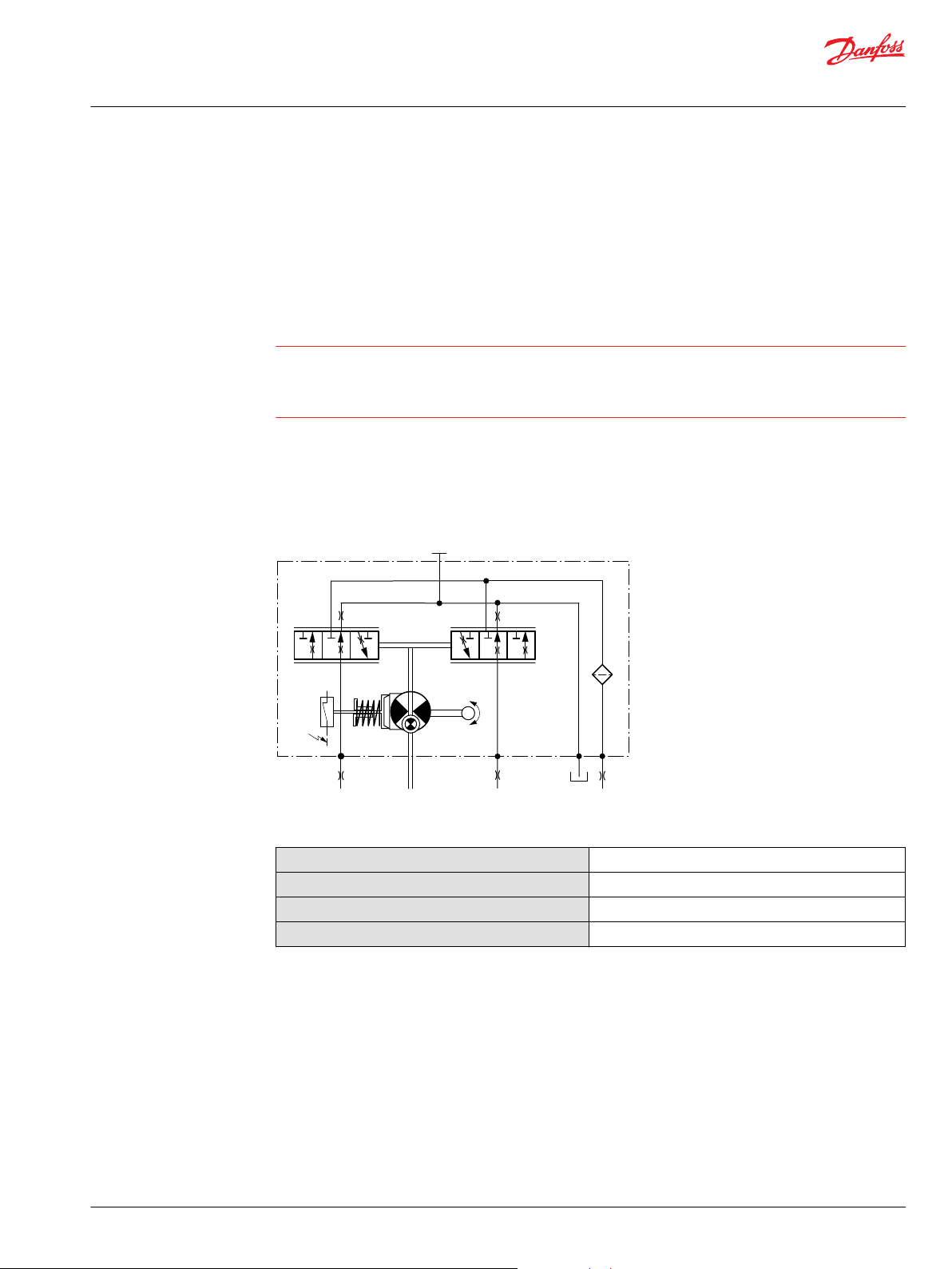
Neutral start switch (NSS)
The Neutral Start Switch (NSS) contains an electrical switch that provides a signal of whether the control
is in neutral. The signal in neutral is Normally Closed (NC).
Neutral start switch schematic
Neutral start switch data
Max. continuous current with switching
Max. continuous current without switching
Max. voltage
Electrical protection class
©
Danfoss | December 2021 BC152886483968en-001001 | 13
8.4 A
20 A
36 V
DC
IP67 / IP69K with mating connector
Page 14
P400520
P400519
X1
F00B
F00A
Feedback from
Swashplate
T P
X2M14
Basic Information
H1 Axial Piston Pumps, Single and Tandem
Operation
Hydraulic Displacement Control (HDC)
HDC principle
An HDC is a Hydraulic Displacement Control. Pump swashplate position is proportional to the input
command and therefore vehicle speed or load speed (excluding influence of efficiency), is dependent
only on the prime mover speed or motor displacement.
The HDC control uses a hydraulic input signal to operate a porting spool, which ports hydraulic pressure
to either side of a double acting servo piston. The hydraulic signal applies a force input to the spool
which ports hydraulic pressure to either side of a double acting servo piston. Differential pressure across
the servo piston rotates the swashplate, changing the pump’s displacement from full displacement in
one direction to full displacement in the opposite direction. Under some circumstances, such as
contamination, the porting spool could stick and cause the pump to stay at some displacement.
A serviceable 175 μm screen is located in the supply line immediately before the control porting spool.
HDC control
HDC schematic
14 | © Danfoss | December 2021 BC152886483968en-001001
Page 15

P003 544
CAN PPC PSC PPU
CC2
CC1
WARRANTY VOID IF REMOVED
CC3
P301 236
C2C1
F00A T PF00B
Basic Information
H1 Axial Piston Pumps, Single and Tandem
Operation
Automotive Control (AC)
The AC-1 and AC-2 propel transmission system consists of an H1 variable pump, embedded electronic
controller, and service tool configurable PLUS+1® software that allows the customer to completely
optimize vehicle performance.
The embedded electronic controller provides an electric input signal activating one of two solenoids that
port charge pressure to either side of the pump servo cylinder. The AC-1 has no mechanical feedback
mechanism but AC-2 is available with an electronic feedback signal for the swashplate position. AC-2 is
an extension of AC-1 that features an integrated pump swashplate angle sensor and software enabled
functions such as swashplate control.
The pump displacement is proportional to the solenoid signal current, but it also depends upon pump
input speed and system pressure. This characteristic also provides a power limiting function by reducing
the pump swash plate angle as system pressure increases. A typical response characteristic is shown in
the accompanying graph.
A serviceable 170 μm screen is located in the supply line immediately before the control porting spool.
Under some circumstances, such as contamination, the control spool could stick and cause the pump to
stay at some displacement.
Automotive Control (AC)
Automotive Control (AC) schematic
©
Danfoss | December 2021 BC152886483968en-001001 | 15
Page 16

Batt.
12/24V
DC
+ -
S 1
1
F 1
2
Terminals
Batt. (+)
Terminals
Batt. (-)
1
2
3
4
5
6
DEUTSCH connector
DTM/6 pin
Sensor A (+)
Analog Input A
Sensor A (-)
Sensor B (-)
PPC
Analog Input B
Sensor B (+)
1
2
3
DEUTSCH connector
DTM/3 pin
CAN High
CAN Low
CAN Shield
CAN
1
2
3
4
5
6
DEUTSCH connector
DTM/6 pin
PWM C1 (+)
PWM C2 (+)
Digital Output A1 (+)
Digital Output A2 (-)
PSC
PWM C2 (-)
PWM C1 (-)
1
2
3
DEUTSCH connector
DTM/3 pin
Sensor (+)
Pump RPM Input (Frequency)
Sensor (-)
PPU
Terminals
Sensor (-)
Terminals
Sensor (+)
CC1p01
CC1p02
CC1p03
CC1p04
Motor RPM/Direction
CC1p05
1
2
3
4
5
6
7
8
9
10
11
12
DEUTSCH connector
DTM/12 pin
Inch Input (Analog-Red)
Mode Switch B Input (Digital-Nom)
Motor PROP/PCOR Output (PWM)
Motor Direction Input (Analog)
Sensor (+)
Sensor (-)
Inch Input (Analog-Nom)
Motor BPD Output (Digital)
Digital Output B2 (-)
Digital Output B1 (+)
Mode Switch A Input (Digital)
Mode Switch B Input (Digital-Red)
CC2
1
2
3
4
5
6
7
8
9
10
11
12
DEUTSCH connector
DTM/12 pin
Battery (-)
Battery (+)
Sensor (+)
Sensor (-)
Motor RPM Input (Frequency)
Forward Input (Digital)
Reverse Input (Digital)
Sensor (+)
Sensor (-)
Drive Pedal Input (Analog-Nom)
Drive Pedal Input (Analog-Red)
Neutral Input (Digital)
CC1
CC2p04
CC1p06
CC1p07
CC1p12
e.g.
Hand Brake
Seat-Switch
FNR
Switch
CC1p08
CC1p09
Rv
Rv
Drive/Creep/Joystick/
Rocker Pedal
CC1p10
CAN Bus
CANp01
CANp02
CANp03
PSCp01
PSCp06
PSCp03
PSCp04
PSCp02
PSCp05
C1
C2
Electronic Displacement
Control Pump
Pump RPM
PPUp02
PPUp03
PPUp01
Mode Switch B
CC2p02
2-P
BPD
PROP
CC2p03
CC2p03
CC2p08
CC2p05
CC2p06
Electronic Displacement
Control Motor
Rv
Rv
Inch Pedal
CC2p07
Alternative Brake
Pressure Inch Sensor
Reverse
Motion
Parking
Brake
CC2p11
CC2p10
CC2p09
CC1p03
CC1p04
CC1p08
CC1p09
PPUp01
PPUp03
CC2p05
CC2p06
CC2p01
CC2p12
CNT
B
A
CC1p11
Mode Switch A
FNR in
Reverse
Brake
Light
Fault
LED
Vehicle-Speed-Dependent
Output-Signal
Reverse
LED
Brake
Light
FNR in
Reverse
Fault
LED
Forward
LED
Brake
Light
3
Nominal
Redundant
3
Reverse
Motion
FNR in
Reverse
1
2
DEUTSCH connector
DT/2 pin
CC3
CC3p01
CC3p02
3
2
1
Contact capability min. 10A
Melting fuse 16A
Functional options
P003 536E
Basic Information
H1 Axial Piston Pumps, Single and Tandem
Operation
Automotive Control connection diagram
16 | © Danfoss | December 2021 BC152886483968en-001001
Page 17

P003 193
P003 189
C2C1
F00A
M14
T PF00B
P003 192
P003 188
C2C1
F00A
M14
T PF00B
Basic Information
H1 Axial Piston Pumps, Single and Tandem
Operation
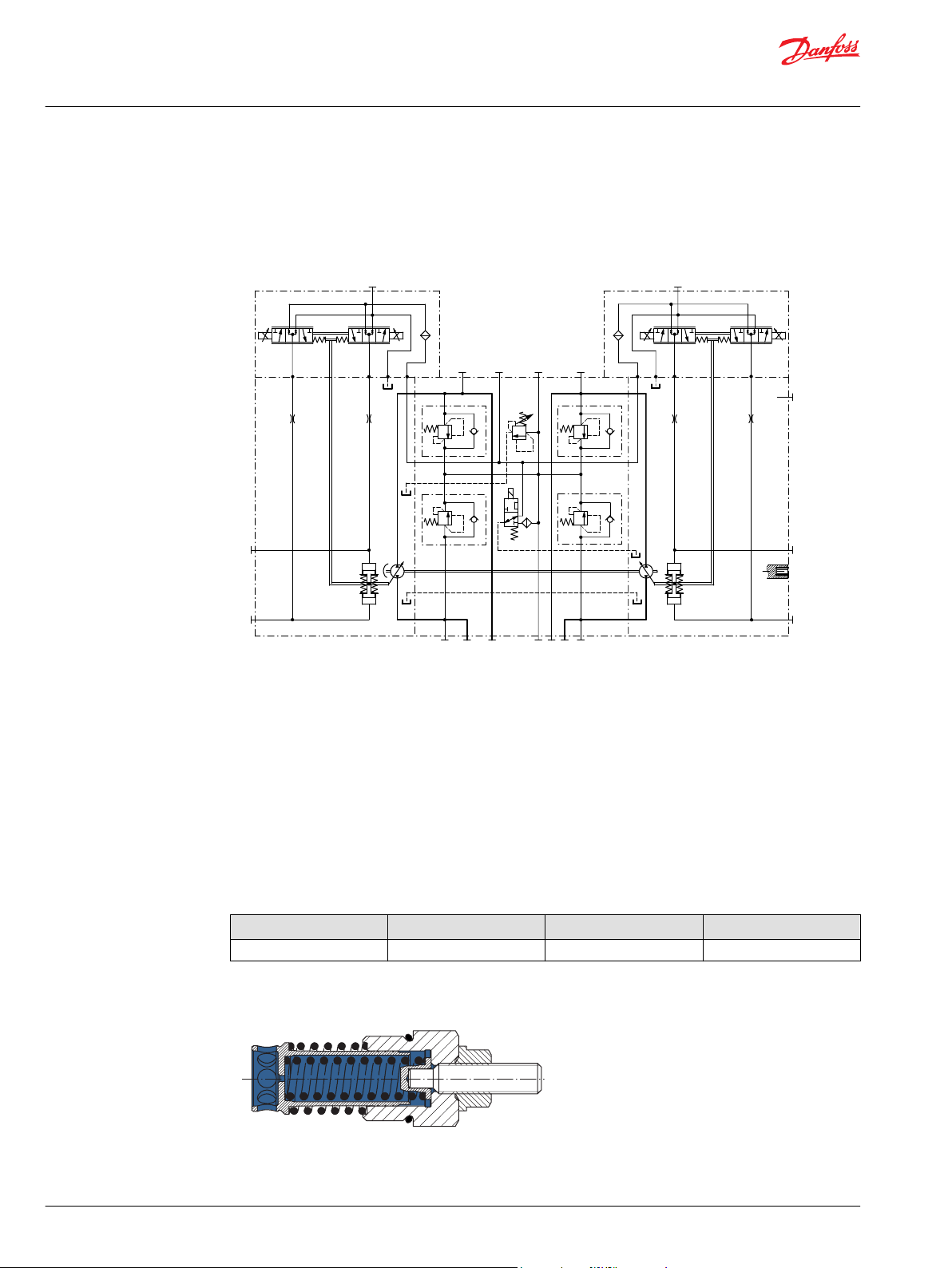
Forward-Neutral-Reverse (FNR) electric control
The 3-Position (F-N-R) control uses an electric input signal to switch the pump to a full stroke position.
A serviceable 170 μm screen is located in the supply line immediately before the control porting spool.
Under some circumstances, such as contamination, the control spool could stick and cause the pump to
stay at some displacement.
FNR control
Non feedback proportional electric control (NFPE)
The Non Feedback Proportional Electric (NFPE) control is an electrical automotive control in which an
electrical input signal activates one of two proportional solenoids that port charge pressure to either side
of the pump servo cylinder. The NFPE control has no mechanical feedback mechanism.
A serviceable 170 μm screen is located in the supply line immediately before the control porting spool.
Under some circumstances, such as contamination, the control spool could stick and cause the pump to
stay at some displacement.
3-Position electric control, hydraulic schematic
NFPE control
©
Danfoss | December 2021 BC152886483968en-001001 | 17
NFPE schematic
Page 18

P301 441
PT
F00B
M14
C1 C2
F00A
P301 442
W
Basic Information
H1 Axial Piston Pumps, Single and Tandem
Operation
Fan Drive Control (FDC)
The Fan Drive Control (FDC) is a non-feedback control in which an electrical input signal activates the
proportional solenoid that ports charge pressure to either side of the pump servo cylinder. The single
proportional solenoid is used to control pump displacement in the forward or reverse direction.
The control spool is spring biased to produce maximum forward pump displacement in the absence of
an electrical input signal. Based on the spring bias spool default forward flow for a CW rotation pump is
out of port B while default forward flow for a CCW rotation pump is out of port A.
Under some circumstances, such as contamination, the control spool could stick and cause the pump to
stay at some displacement.
FDC control
FDC schematic
The pump should be configured with 0.8 mm control orifices to provide slowest response and maximize
system stability. Additionally, pressure limiter (PL) valves are used to limit maximum fan trim speed in
both (forward and reverse) directions.
H1 pumps with FDC will be delivered from factory with nominal pressure limiter setting of 150 bar [2175
psi]. The PL must be re-adjusted to ensure that the fan reaches the desired fan speed to satisfy the
cooling needs of the system. HPRV setting must be always at least 30 bar [435 psi] higher than PL setting.
For more information necessary to properly size and configure a hydraulic fan drive system, see Hydraulic
Fan Drive Design Guidelines AB152886482265.
Warning
Use in other systems could result in unintended movement of the machine or it’s elements. Loss of the
input signal to this control will cause the pump to produce maximum flow.
The FDC is for Fan Drive systems only!
Due to the fail-safe functionality of the FDC control the pump will stroke to max. displacement in case the
input signal to the pump control and the Diesel engine will be switched off at the same time. In this
situation a low loop event can occur which may damage the pump. Therefore, it’s strictly recommended
to keep the input signal to the pump control alive while switching off the engine.
For further information please contact your Danfoss representative.
Control Signal Requirements, FDC
The pump displacement is proportional to the solenoid signal current, but it also depends upon pump
input speed and system pressure. This characteristic also provides a power limiting function by reducing
18 | © Danfoss | December 2021 BC152886483968en-001001
Page 19
100%
100%
Displacement
0
Signal current (mA(DC
Avg
))
Max. current
N
a
b
∆
p = 0 bar
∆
p = 0 bar
∆
p = 300 bar
Reverse
Forward
Basic Information
H1 Axial Piston Pumps, Single and Tandem
Operation
the pump swash plate angle as system pressure increases. A typical response characteristic is shown in
the accompanying graph below:
a – Forward threshold
b – Reverse threshold
N – Neutral override current
Control current requirements
*
Voltage
12 V
DC
24 V
DC
*
Factory test current, for fan movement expect higher or lower value.
a N b Pin config.
780 mA 1100 mA 1300 mA
400 mA 550 mA 680 mA
any order
©
Danfoss | December 2021 BC152886483968en-001001 | 19
Page 20

P003 204
PTF00B
M14
C2
C1
F00A
W
Basic Information
H1 Axial Piston Pumps, Single and Tandem
Operation
Manual Override (MOR)
All controls are available with a manual override functionality, either as a standard or as an option for
temporary actuation of the control to aid in diagnostics.
Control with manual override
MOR schematic (EDC control shown)
Feedback from swash plate.
The MOR plunger has a 4 mm diameter and must be manually depressed to be engaged. Depressing the
plunger mechanically moves the control spool which allows the pump to go on stroke. The MOR should
be engaged anticipating a full stroke response from the pump.
An o-ring seal is used to seal the MOR plunger where initial actuation of the function will require a force
of 45 N to engage the plunger. Additional actuation typically require less force to engage the MOR
plunger.
Proportional control of the pump using the MOR should not be expected.
Warning
Unintended MOR operation will cause the pump to go into stroke; example: vehicle lifted off the ground.
The vehicle or device must always be in a safe condition when using the MOR function.
Refer to control flow table for the relationship of solenoid to direction of flow.
20 | © Danfoss | December 2021 BC152886483968en-001001
Page 21

-18° -13° -8°
100%
90%
80%
70%
60%
50%
40%
30%
20%
10%
0%
Swashplate angle
Sensor output, % of supply voltage
-3° 0° 2° 7° 12° 17°
W
Basic Information
H1 Axial Piston Pumps, Single and Tandem
Operation
Swashplate angle sensor for EDC controls
The angle sensor detects the swash plate position with an accuracy dependent upon the calibration
effort done for the application and direction of rotation from the neutral position. At minimum the sensor
can be used for forward, neutral and reverse (FNR) detection.
The sensor works on the hall-effect technology. The implemented technology is based on a
measurement of the magnetic field direction in parallel to the chip surface. This field direction is
converted to a voltage signal at the output.
Enhanced calibration of the non-linear behavior leads to more exact calculation of the pump swashplate
angle. The 4-pin DEUTSCH connector is part of the sensor housing. The swashplate angle sensor is
available for all EDC controls for 12 V and 24 V.
Swashplate angle vs. output of supply voltage
Warning
Strong magnetic fields in the proximity of the sensor can influence the sensor signal and must be
avoided.
Contact your Danfoss representative in case the angle sensor will be used for safety functions.
©
Danfoss | December 2021 BC152886483968en-001001 | 21
Page 22

P301 750
-25° -20° -15° -10° -5° 0° 5° 10° 15° 20° 25°
5
4.5
4
3.5
3
2.5
2
1.5
1
0.5
0
Swashplate angle
Output voltage (V)
1
2
Basic Information
H1 Axial Piston Pumps, Single and Tandem
Operation
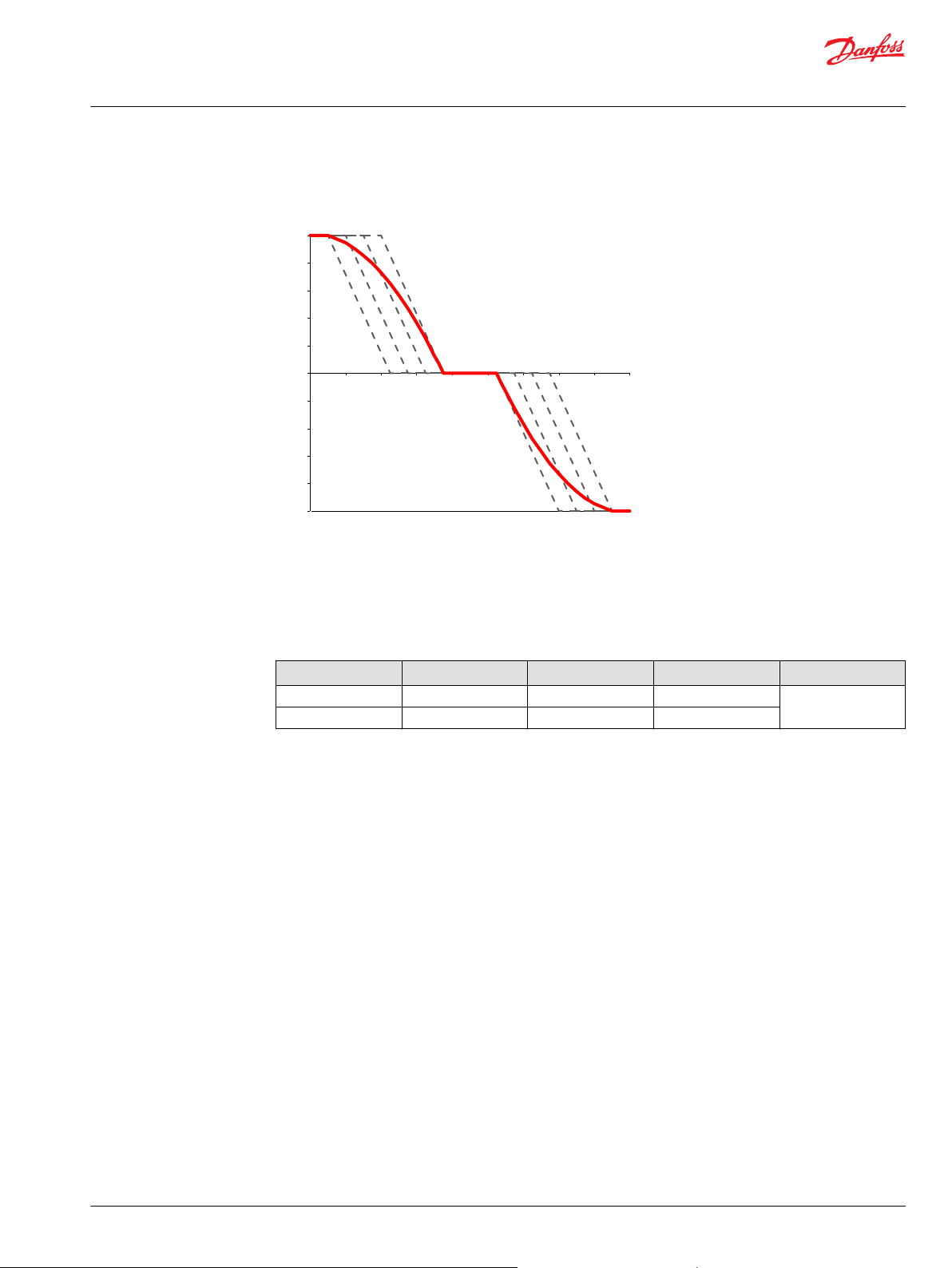
Swash Plate Angle Sensor for NFPE and AC2 Controls
The angle sensor detects the swash plate angle position and direction of rotation from the zero position.
The swash angle sensor works on the AMR sensing technology. Under the saturated magnetic field, the
resistance of the element varies with the magnetic field direction.
The output signal give a linear output voltage for the various magnet positions in the sensing range.
Swash plate angle vs. output voltage
22 | © Danfoss | December 2021 BC152886483968en-001001
Page 23
P005 703
M14
X7
C
Basic Information
H1 Axial Piston Pumps, Single and Tandem
Operation
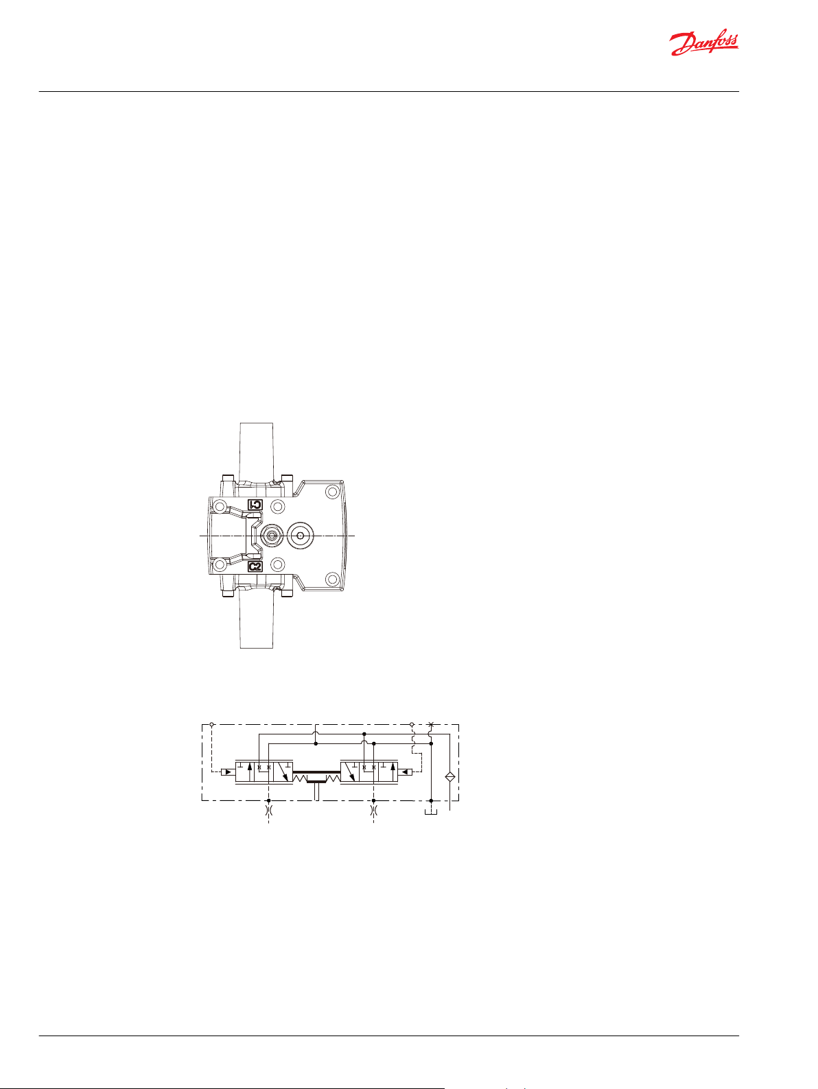
Control Cut Off Valve (CCO)
The H1 pump offers an optional control cut off valve integrated into the control. All EDC, NFPE and MDC
controls are available with a CCO valve. This valve will block charge pressure to the control, allowing the
servo springs to de-stroke both pumps regardless of the pump´s primary control input.
There is also a hydraulic logic port, X7, which can be used to control other machine functions, such as
spring applied pressure release brakes. The pressure at X7 is controlled by the control cut off solenoid.
The X7 port would remain plugged if not needed.
In the normal (de-energized) state of the solenoid charge flow is prevented from reaching the controls. At
the same time the control passages and the X7 logic port are connected and drained to the pump case.
The pump will remain in neutral, or return to neutral, independent of the control input signal. Return to
neutral time will be dependent on oil viscosity, pump speed, swashplate angle, and system pressure.
When the solenoid is energized, charge flow and pressure is allowed to reach the pump control. The X7
logic port will also be connected to charge pressure and flow.
The solenoid control is intended to be independent of the primary pump control making the control cut
off an override control feature. It is however recommended that the control logic of the CCO valve be
maintained such that the primary pump control signal is also disabled whenever the CCO valve is deenergized. Other control logic conditions may also be considered.
The CCO valve is available with 12 V or 24 V solenoid.
The response time of the unit depends on the control type and the used control orifices.
CCO schematic (MDC shown)
Brake gauge port with MDC
Caution
It is not recommended to use brake port for any external flow consumption to avoid malfunction of CCO
function.
©
Danfoss | December 2021 BC152886483968en-001001 | 23
Page 24
P003 266
Basic Information
H1 Axial Piston Pumps, Single and Tandem
Operation
Displacement Limiter
H1 pumps are designed with optional mechanical displacement (stroke) limiters factory set to max.
displacement. The maximum displacement of the pump can be set independently for forward and
reverse using the two adjustment screws to mechanically limit the travel of the servo piston down to 50%
displacement.
Adjustments under operating conditions may cause leakage. The adjustment screw can be completely
removed from the threaded bore if backed out to far.
Life Time
Hydraulic unit life depends on the speed and normal operating, or weighted average, pressure that can
only be determined from a duty cycle analysis.
The life of the product depends on several factors, such as speed, pressure, swash plate angle, to name a
few.
For detailed product life calculation, please contact your Danfoss representative.
24 | © Danfoss | December 2021 BC152886483968en-001001
Page 25

Basic Information
H1 Axial Piston Pumps, Single and Tandem
Operation
Speed and Temperature Sensor
Description
Function of the speed sensor is to detect the shaft speed. Typically the sensor is mounted to the housing
of a Danfoss pump or motor and senses the speed from a target ring that is rotating inside the pump or
motor.
Because of the digital output signals for speed the sensor is ideal for high and low speed measurements.
The speed sensor is designed for rugged outdoor, mobile or heavy industrial speed sensing applications.
The detection of the speed is contactless. It is custom-designed for Danfoss. It is a Plug and Perform device
that does not need any calibration or adjustments.
For diagnostics and other purposes, some sensor also has the capability to detect the driving direction
and the case oil temperature.
Theory of Operation
The speed sensor is externally powered and, in response to the speed of the target ring, outputs a digital
pulse signal. A magnet inside the sensor provides the magnetic field that changes with the position of
the target teeth.
The target ring is attached to the cylinder block or the shaft. Hall sensors change from high/low state as
the target teeth pass by the sensor´s face. The digital (on-off-on-off ) pulse train is fed to a controller,
which interprets its rate of change as a speed.
Some speed sensor uses two Hall sensors with specific distance and orientation resulting in a pulse train
output shift of 90° between the two sensors. A logic circuit decodes the two signals to provide an
additional direction indication (high or low depending on direction).
Due to the design of the sensor, the duty cycle (ratio between on and off time at constant speed) of both
speed signals at any working condition is close to 50 % and can be used for better resolution at low
speeds.
Target Ring
Speed (target) rings vary according to the diameter of the cylinder block or shaft on which they are
installed. The number of teeth is shown in the table below.
The number of speed (target) ring teeth
H1P size 045/053 060/068 069/078 089/100 115/130 147/165 210/250
Teeth 79 86 86 92 102 108 90
Mating Connectors
Mating connectors ordering data.
Ordering data
Description Quantity Ordering number
Mating connector 1 DEUTSCH DT06-6S
Wedge lock 1 DEUTSCH WM65
Socket contact (16 and 18 AWG) 6 DEUTSCH 0462-201-2031
DEUTSCH mating connector kit 1 11033865
©
Danfoss | December 2021 BC152886483968en-001001 | 25
Page 26

4
3
2
1
5
6
P006035
T = –1481.96 + √ 2.1962 · 106 +
(1.8639 – Vº)
3.88 · 10
-6
Basic Information
H1 Axial Piston Pumps, Single and Tandem
Operation
Speed sensor 4.5 – 8 V technical data
Speed sensor connector, 6-pin
1. Speed signal 2
2. Direction signal
3. Speed signal 1
4. Supply
5. Ground
6. Temperature
Technical data
Parameter Min. Nom. Max. Note
Supply voltage
Supply protection
Max. required supply current
Max. output current
Operation mode
Temperature signal
Output low
Output high
Detectable frequency range
Ordering number
Color of connector
4.5 V
DC
– – 30 V
– – 25 mA At supply voltage
– – 50 mA
NPN & PNP Push-Pull amplifier
-40°C = 2.318V – 100°C = 0.675V
5 % 8.5 % 12 %
88 % 91.5 % 95 %
1 Hz – 10 000 Hz
149055
Black
5 V
8 V
DC
DC
DC
Regulated supply voltage.
Reverse polarity protected.
Shuts off above 9 V.
Ratiometric output voltage
Low state > 0 V to provide wire
fault detection
Temperature sensor data
For calculation of the case fluid temperature and the output signal voltage, see the formulas below:
VO – Measured output voltage (V)
Vo= (-3.88 • 10-6 • T2) + (-1.15 • 10-2 • T) + 1.8639
T – Temperature (°C)
Output signal voltage vs. Temperature
Temperature range
-55 °C** -40 °C -30 °C 0 °C +30 °C
2.485 V 2.318 V 2.205 V 1.864 V 1.515 V 0.919 V 0.675 V 0.303 V
*
Accuracy: ±1. 5 to ± 4 °C
**
Accuracy: ±2.5 to ± 5 °C
*
+80 °C +100 °C +130 °C
26 | © Danfoss | December 2021 BC152886483968en-001001
**
Page 27

0
0
10
20
30
40
50
60
70
80
90
-100 100 200 300 400 500 600 700 800 900 1000
P003531E
Real temperature
Temperature
Signal
T90 definition
T
90
Time (S)
Temperature (°C)
90 % of ∆ Temp
∆ Temp
Basic Information
H1 Axial Piston Pumps, Single and Tandem
Operation
Response time in fluid
T90 definition
Response time in fluid (T90) = 360 s
©
Danfoss | December 2021 BC152886483968en-001001 | 27
Page 28

W
Basic Information
H1 Axial Piston Pumps, Single and Tandem
Operating Parameters
Input Speed
System Pressure
Minimum
speed
Rated speed is the highest input speed recommended at full power condition. Operating at or
Maximum
speed
During hydraulic braking and downhill conditions, the prime mover must be capable of providing
sufficient braking torque in order to avoid pump over speed. This is especially important to consider for
turbo-charged and Tier 4 engines.
For more information please see Pressure and Speed Limits, BC152886484313, when determining speed
limits for a particular application.
Hydraulic unit life depends on the speed and normal operating — or weighted average — pressure that
can only be determined from a duty cycle analysis.
is the lowest input speed recommended during engine idle condition. Operating below
minimum speed limits the pump’s ability to maintain adequate flow for lubrication and
power transmission.
below this speed should yield satisfactory product life.
Operating conditions between rated and maximum speed should be restricted to less
than full power and to limited periods of time.
is the highest operating speed permitted. Exceeding maximum speed reduces product
life and can cause loss of hydrostatic power and braking capacity. For most drive
systems, maximum unit speed occurs during downhill braking or negative power
conditions.
Warning
Never exceed the maximum speed limit under any operating conditions.
System pressure is the differential pressure between high pressure system ports. It is the dominant
operating variable affecting hydraulic unit life. High system pressure, which results
from high load, reduces expected life.
Application
pressure
Maximum
working
pressure
Maximum
pressure
Minimum low
loop pressure
is the high pressure relief or pressure limiter setting normally defined within the
order code of the pump. This is the applied system pressure at which the drive line
generates the maximum calculated pull or torque in the application.
is the highest recommended application pressure and is not intended to be a
continuous pressure. Propel systems with application pressures at, or below this
pressure should yield satisfactory unit life given proper component sizing.
Application pressures above maximum working pressure will only be considered
with duty cycle analysis and factory approval.
Pressure spikes are normal and must be considered when reviewing maximum
working pressure.
is the highest intermittent pressure allowed under any circumstances. Applications
with applied pressures between rated and maximum require factory approval with
complete application, duty cycle, and life expectancy analysis.
must be maintained under all operating conditions to avoid cavitation.
All pressure limits are differential pressures referenced to low loop (charge) pressure.
Subtract low loop pressure from gauge readings to compute the differential.
28 | © Danfoss | December 2021 BC152886483968en-001001
Page 29

Basic Information
H1 Axial Piston Pumps, Single and Tandem
Operating Parameters
Servo Pressure
Servo pressure is the pressure in the servo system needed to position and hold the pump on stroke. It
depends on system pressure and speed. At minimum servo pressure the pump will run at reduced stroke
depending on speed and pressure.
Minimum servo pressure at corner power holds the pump on full stroke at max speed and max
Maximum servo pressure is the highest pressure typically given by the charge pressure setting.
Charge Pressure
An internal charge relief valve regulates charge pressure. Charge pressure supplies the control with
pressure to operate the swashplate and to maintain a minimum pressure in the low side of the
transmission loop.
The charge pressure setting listed in the order code is the set pressure of the charge relief valve with the
pump in neutral, operating at 1800 min-1 (rpm), and with a fluid viscosity of 32 mm2/s [150 SUS].
Pumps configured with no charge pump (external charge supply) are set with a charge flow of 30 l/min
[7.93 US gal/min] and a fluid viscosity of 32 mm2/s [150 SUS].
The charge pressure setting is referenced to case pressure. Charge pressure is the differential pressure
above case pressure.
pressure.
Charge Pump Inlet Pressure
Case Pressure
Minimum
charge
pressure
Maximum
charge
pressure
At normal operating temperature charge inlet pressure must not fall below rated charge inlet pressure
(vacuum).
Minimum charge inlet
pressure
Maximum charge inlet
pressure
Under normal operating conditions, the rated case pressure must not be exceeded. During cold start case
pressure must be kept below maximum intermittent case pressure. Size drain plumbing accordingly.
The auxiliary pad cavity of axial pumps configured without integral charge pumps is referenced to case
pressure. Units with integral charge pumps have auxiliary mounting pad cavities referenced to charge
inlet (vacuum).
is the lowest pressure allowed to maintain a safe working condition in the low side of
the loop. Minimum control pressure requirements are a function of speed, pressure,
and swashplate angle, and may be higher than the minimum charge pressure shown
in the Operating parameters tables.
is the highest charge pressure allowed by the charge relief adjustment, and which
provides normal component life. Elevated charge pressure can be used as a
secondary means to reduce the swashplate response time.
is only allowed at cold start conditions. In some applications it is
recommended to warm up the fluid (e.g. in the tank) before starting the
engine and then run the engine at limited speed.
may be applied continuously.
Possible component damage or leakage.
Operation with case pressure in excess of stated limits may damage seals, gaskets, and/or housings,
causing external leakage. Performance may also be affected since charge and system pressure are
additive to case pressure.
©
Danfoss | December 2021 BC152886483968en-001001 | 29
Page 30

C
Basic Information
H1 Axial Piston Pumps, Single and Tandem
Operating Parameters
External Shaft Seal Pressure
In certain applications the input shaft seal may be exposed to external pressure. In order to prevent
damage to the shaft seal the maximum differential pressure from external sources must not exceed 0.4
bar (5.8 psi) over pump case pressure.
The case pressure limits of the pump must also be followed to ensure the shaft seal is not damaged.
Caution
Regardless of the differential pressure across the shaft seal, the shaft seal has been known to pump oil
from the external source (e. g. gear box) into the pump case.
Temperature
The high temperature limits apply at the hottest point in the transmission, which is normally the motor
case drain. The system should generally be run at or below the quoted rated temperature.
The maximum intermittent temperature is based on material properties and should never be
exceeded.
Cold oil will generally not affect the durability of the transmission components, but it may affect the
ability of oil to flow and transmit power; therefore temperatures should remain 16 °C [30 °F] above the
pour point of the hydraulic fluid.
The minimum temperature relates to the physical properties of component materials.
Size heat exchangers to keep the fluid within these limits. Danfoss recommends testing to verify that
these temperature limits are not exceeded.
Viscosity
For maximum efficiency and bearing life, ensure the fluid viscosity remains in the recommended range.
The minimum viscosity should be encountered only during brief occasions of maximum ambient
temperature and severe duty cycle operation.
The maximum viscosity should be encountered only at cold start.
30 | © Danfoss | December 2021 BC152886483968en-001001
Page 31

C
Basic Information
H1 Axial Piston Pumps, Single and Tandem
System design parameters
Fluid Specification
Viscosity
Intermittent
Minimum
Recommended range
Maximum
1)
Intermittent = Short term t < 1 min per incident and not exceeding 2 % of duty cycle based load-life.
Temperature
Minimum
Rated
Recommended range
Maximum Intermittent
1)
Cold start = Short term t > 3 min, p ≤ 50 bar [725 psi], n ≤ 1000 min-1 (rpm).
2)
At the hottest point, normally case drain port.
1)
1)
2)
5 mm2/s [42 SUS]
7 mm2/s [49 SUS]
12 – 80 mm2/s [66 – 370 SUS]
1600 mm2/s [7500 SUS]
-40°C [-40°F]
104°C [220°F]
60 – 85°C [140 – 185°F]
115°C [240°F]
Fluid selection
Ratings and performance data are based on operating with hydraulic fluids containing oxidation, rust
and foam inhibitors. These fluids must possess good thermal and hydrolytic stability to prevent wear,
erosion, and corrosion of pump components.
Caution
Never mix hydraulic fluids of different types.
©
Danfoss | December 2021 BC152886483968en-001001 | 31
Page 32

Basic Information
H1 Axial Piston Pumps, Single and Tandem
System design parameters
Filtration System
To prevent premature wear, ensure only clean fluid enters the hydrostatic transmission circuit. A filter
capable of controlling the fluid cleanliness to ISO 4406 class 22/18/13 (SAE J1165) or better, under normal
operating conditions, is recommended.
These cleanliness levels can not be applied for hydraulic fluid residing in the component housing/case or
any other cavity after transport.
The filter may be located on the pump (integral) or in another location (remote). The integral filter has a
filter bypass sensor to signal the machine operator when the filter requires changing. Filtration strategies
include suction or pressure filtration.
The selection of a filter depends on a number of factors including the contaminant ingression rate, the
generation of contaminants in the system, the required fluid cleanliness, and the desired maintenance
interval. Filters are selected to meet the above requirements using rating parameters of efficiency and
capacity.
Filter efficiency can be measured with a Beta ratio (βX). For simple suction filtered closed circuit
transmissions and open circuit transmissions with return line filtration, a filter with a β-ratio within the
range of β
For some open circuit systems, and closed circuits with cylinders being supplied from the same reservoir,
a considerably higher filter efficiency is recommended. This also applies to systems with gears or clutches
using a common reservoir.
For these systems, a charge pressure or return filtration system with a filter β-ratio in the range of β
75 (β10 ≥ 10) or better is typically required.
Because each system is unique, only a thorough testing and evaluation program can fully validate the
filtration system.
Please see Design Guidelines for Hydraulic Fluid Cleanliness Technical Information, BC152886482150 for
more information.
= 75 (β10 ≥ 2) or better has been found to be satisfactory.
35-45
15-20
=
Filter βx-ratio is a measure of filter efficiency defined by ISO 4572. It is defined as the ratio of the number
of particles greater than a given diameter (“x” in microns) upstream of the filter to the number of these
particles downstream of the filter.
Filtration, cleanliness level and βx-ratio (recommended minimum)
Cleanliness per ISO 4406
Efficiency βx (charge pressure filtration)
Efficiency βx (suction and return line filtration)
Recommended inlet screen mesh size
22/18/13
β
= 75 (β10 ≥ 10)
15-20
β
= 75 (β10 ≥ 2)
35-45
100 – 125 µm
32 | © Danfoss | December 2021 BC152886483968en-001001
Page 33

P003 471E
Reservoir
Strainer
Filter
Charge
pump
Charge
relief
valve
to pump case
to low pressure
side of loop
and servo control
Reservoir
Charge
pump
Charge
relief
valve
to pump case
to low pressure
side of loop
and servo
control
Strainer
P003 472E
Filter with bypass
Bypass
Filter bypass
sensor
Basic Information
H1 Axial Piston Pumps, Single and Tandem
System design parameters
Suction Filtration
The suction filter is placed in the circuit between the reservoir and the inlet to the charge pump.
Suction filtration
Possible charge pump damage. Clogged filters can cause cavitation, which damages the charge pump.
We recommend a filter bypass with a filter bypass sensor to prevent damage due to blocked suction
filters.
Charge pressure filtration (full charge pump flow)
Charge pressure filtration can mitigate high inlet vacuum in cold start-ups and provides fluid filtration
immediately prior to entrance to the loop and the control system. Pressure filtration provides a higher
level of filtering efficiency than suction filtration.
For most H1 pumps exist two types of pressure filtration:
•
remote pressure filtration (filter remotely mounted on vehicle)
•
integral pressure filtration (filter mounted to the endcap)
Remote charge pressure filtration, full flow
©
Danfoss | December 2021 BC152886483968en-001001 | 33
Page 34

Reservoir
Charge
pump
Charge
relief
valve
to pump case
to low pressure
side of loop
and servo
control
Strainer
P003 473E
Filter with bypass
Bypass
Filter bypass
sensor
Basic Information
H1 Axial Piston Pumps, Single and Tandem
System design parameters
Integral charge pressure filtration, full flow
Verify option availability in the size specific technical information. In either case the filtration circuit is the
same with the filter element situated in the circuit downstream the charge pump and upstream of the
charge relief valve such that full charge flow is continuously filtered.
Filters used in charge pressure filtration circuits must be rated to at least 35 bar [508 psi] pressure. A 100 –
125 µm screen located in the reservoir or in the charge inlet line is recommended when using charge
pressure filtration.
A filter bypass valve is necessary to prevent filter damage and to avoid contaminants from being forced
through the filter media by high pressure differentials across the filter.
In the event of high pressure drop associated with a blocked filter or cold start-up conditions, fluid will
bypass the filter. Working with an open bypass should be avoided.
Remote Charge Pressure Filtration
Ports at the endcap are available to allow for the charge filter to be located conveniently for easy service
and replacement.
Possible charge pump damage. Remote filter heads without bypass and poor plumbing design can
encounter excessive pressure drops that can lead to charge pump damage in addition to contaminants
being forced through the filter media and into the transmission loop.
Care should be taken to minimize the hydraulic pressure drops associated with long connecting lines,
small diameter hoses, or restrictive port adaptors at the filter head or endcap. Ensure the normal
operating pressure drop across the remote filtration in and out ports is sufficiently below the crack
pressure setting of the recommended filter bypass valve.
34 | © Danfoss | December 2021 BC152886483968en-001001
Page 35

Bypass spool
Filter
bypass sensor
Filter
element
P003 359E
Basic Information
H1 Axial Piston Pumps, Single and Tandem
System design parameters
Integral Charge Pressure Filtration
The H1 integral pressure filter head is designed with a filter bypass valve and non-contacting bypass
sensor. The pressure differential acting on the filter element also acts on a spring biased bypass spool.
This spool is designed with a magnetic area. When a certain spool position is reached, the magnet closes
a switch in the bypass sensor which allows R2 to be in parallel with R1. This occurs without any
mechanical contact between the spool and the bypass sensor.
The position of the bypass spool is indicated by the change in the measured sensor resistance. The
change in resistance occurs when R2 is switched in and out of the circuit.
When the filter is not being bypassed, the nominal measured resistance is 510 Ω. When the switch is
closed, the nominal measured resistance is 122 Ω.
The bypass spool is designed so the bypass sensor switch will be closed before oil bypasses the filter
element. This gives the machine operator an indication that the filter is very close to bypassing and a
filter replacement is required.
For cold start conditions, it is typical that the filter may bypass for a short amount of time while the oil is
warming up. At normal operating oil temperatures, a system that does not yet need a filter replacement
will operate in the non-bypass mode. The addition of an oil temperature sensor and additional control
logic, is recommended to properly determine if a filter replacement is required.
Integral filter head with filter bypass sensor
Pressure data
Filter bypass sensor switch closure ∆p Bypass valve ∆p above sensor setting
4.5 ±0.8 bar [62.27 ±11.6 psi] 1.2 ±0.2 bar [17.4 ±2.9 psi]
Electric data
Max. voltage
Max. power
Switch: open / closed
Resistor tolerance
Temperature range
IP Rating (IEC 60 529) + DIN 40 050
Nominal flow at 30 mm²/s and Δp 0.5 bar [7.3 psi]
Short 60 l/min
Medium 80 l/min
Long 105 l/min
©
Danfoss | December 2021 BC152886483968en-001001 | 35
48 V
0.6 W
510 / 122 Ω
1 %
-20 ÷ +100 °C [-4 ÷ +212 °F]
IP 69K part 9 with mating connector
Min β
(c) = 75 (β5 (c) ≥ 10) according to ISO 16889
7.5
(clean filter element only)
Page 36
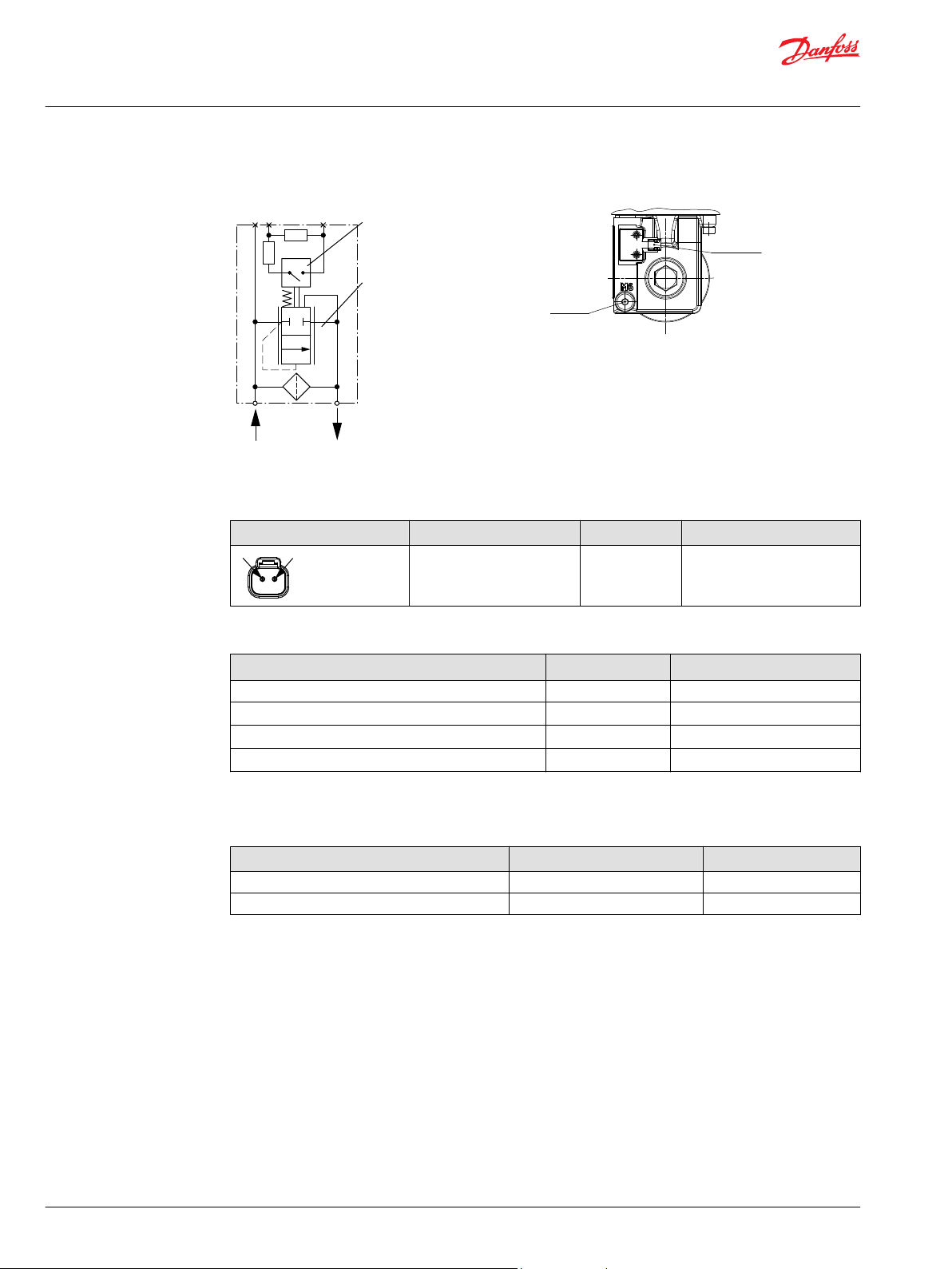
P003 195
21
M6
out
in
R1
R2
Bypass sensor
open
Bypass valve
closed
P003 198E
Connector
Deutsch DTM04-2P
M6
9
/
16
-18
before filter (upstream)
2
1
Basic Information
H1 Axial Piston Pumps, Single and Tandem
System design parameters
Schematic
Connector
Connector pin assignment (any order)
Connector Pin assignment Or Pin assignment
1. Supply
2. Ground (GND)
Alternative
1. Ground (GND)
2. Supply
H1 filter bypass sensor mating connector parts list
Description Quantity Order number
Mating connector 1 DEUTSCH DTM06-2S
Secondary wedge lock 1
Socket terminal 2
Danfoss mating connector kit 1
DEUTSCH WM-2S
DEUTSCH 0462-201-20141
11031205
H1P Filters Ordering Numbers
The H1 pumps with an integrated filter option are shipped with a filter of length as indicated below:
H1 pump size Filter element length Ordering number
H1P 069/078, 089/100 Medium 11004918
H1P 115/130, 147/165 Long 11004919
36 | © Danfoss | December 2021 BC152886483968en-001001
Page 37
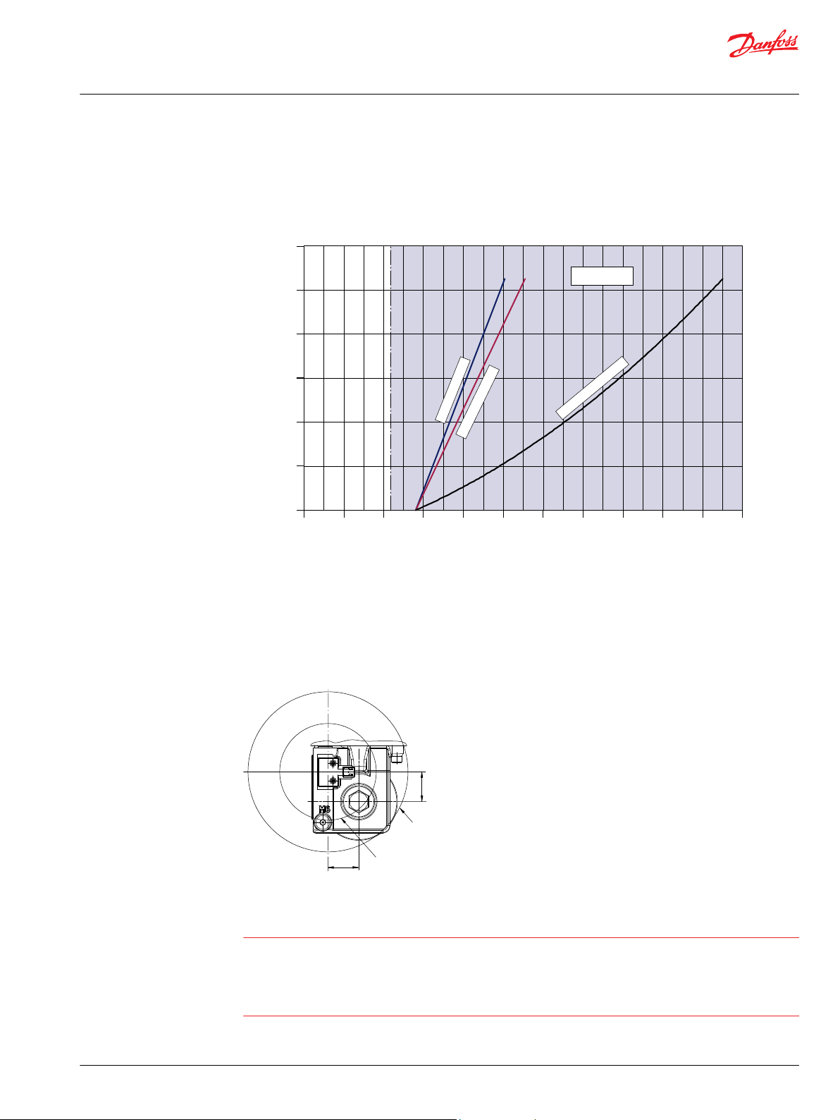
0
20
[5.28]
40
[10.57]
60
[15.85]
80
[21.13]
100
[26.42]
120
[31.70]
0
22
[319]
20
[290]
18
[261]
16
[232]
14
[203]
12
[174]
10
[145]
8
[116]
6
[87]
4
[58]
2
[29]
Flow l/min [US gal/min]
Differential pressure over filter bypass bar [psi]
(blocked filter element)
P003 185E
Filter bypass
sensor activated
8 mm
2
/s [52 SUS]
74 mm
2
/s [342 SUS]
1600 mm
2
/s [7406 SUS]
P003 356E
mm
[in]
38
[1.50]
150 min
[5.91]
250 min
[9.84]
37
[1.46]
Basic Information
H1 Axial Piston Pumps, Single and Tandem
System design parameters
Filter Bypass Characteristic
The diagram below shows the differential pressure between filter in and out with a filter element
completely blocked, so that all flow runs across the filter bypass valve.
Filter bypass characteristic (completely blocked element)
Bypass Sensor Clearance
The bypass sensor is activated by the magnetic bypass valve.
No steel parts are allowed within a radius of 150 mm [5.91 in]. Moving steel devices or parts are not
allowed within a radius of 250 mm [9.84 in].
Independent Braking System
Unintended vehicle or machine movement hazard. Exceeding maximum speed may cause a loss of
hydrostatic drive line power and braking capacity.
Machine manufacturer is responsible to provide a braking system, redundant to the hydrostatic
transmission, sufficient to stop and hold the vehicle or machine in the event of hydrostatic drive power
loss. The braking system must also be sufficient to hold the machine in place when full power is applied.
©
Danfoss | December 2021 BC152886483968en-001001 | 37
Page 38

Basic Information
H1 Axial Piston Pumps, Single and Tandem
System design parameters
Reservoir
The hydrostatic system reservoir should accommodate maximum volume changes during all system
operating modes and promote de-aeration of the fluid as it passes through the tank. A suggested
minimum total reservoir volume is 5⁄8 of the maximum charge pump flow per minute with a minimum
fluid volume equal to ½ of the maximum charge pump flow per minute. This allows 30 seconds fluid
dwell for removing entrained air at the maximum return flow. This is usually adequate to allow for a
closed reservoir (no breather) in most applications.
Locate the reservoir outlet (charge pump inlet) above the bottom of the reservoir to take advantage of
gravity separation and prevent large foreign particles from entering the charge inlet line. A 100-125 µm
screen over the outlet port is recommended. Position the reservoir inlet (fluid return) to discharge below
the normal fluid level, toward the interior of the tank. A baffle (or baffles) will further promote de-aeration
and reduce surging of the fluid.
Case drain
All single H1 pumps are equipped with multiple drain ports whereas some H1 pumps are equipped with
two case drain port sizes. Port selection and case drain routing must enable the pump housing to
maintain a volume of oil not less than half full and normal operating case pressure limits of the unit are
maintained. Case drain routing and design must consider unit case pressure ratings.
A case drain line must be connected to one of the case outlets to return internal leakage to the system
reservoir.
38 | © Danfoss | December 2021 BC152886483968en-001001
Page 39

Basic Information
H1 Axial Piston Pumps, Single and Tandem
System design parameters
Charge pump
Charge flow is required on all H1 pumps applied in closed circuit installations. The charge pump provides
flow to make up internal leakage, maintain a positive pressure in the main circuit, provide flow for
cooling and filtration, replace any leakage losses from external valving or auxiliary systems, and to
provide flow and pressure for the control system.
Many factors influence the charge flow requirements and the resulting charge pump size selection. These
factors include system pressure, pump speed, pump swashplate angle, type of fluid, temperature, size of
heat exchanger, length and size of hydraulic lines, control response characteristics, auxiliary flow
requirements, hydrostatic motor type, etc. When initially sizing and selecting hydrostatic units for an
application, it is frequently not possible to have all the information necessary to accurately evaluate all
aspects of charge pump size selection.
Unusual application conditions may require a more detailed review of charge pump sizing. Charge
pressure must be maintained at a specified level under all operating conditions to prevent damage to the
transmission. Danfoss recommends testing under actual operating conditions to verify this.
Charge pump sizing/selection
In most applications a general guideline is that the charge pump displacement should be at least 10 % of
the total displacement of all components in the system. Unusual application conditions may require a
more detailed review of charge flow requirements. Please refer to Selection of Drive Line Components,
BC157786484430 for a detailed procedure.
System features and conditions which may invalidate the 10 % guideline include (but are not limited to):
•
Continuous operation at low input speeds (< 1500 min-1 (rpm))
•
High shock loading and/or long loop lines
•
High flushing flow requirements
•
Multiple Low Speed High Torque motors
•
High input shaft speeds
©
Danfoss | December 2021 BC152886483968en-001001 | 39
Page 40
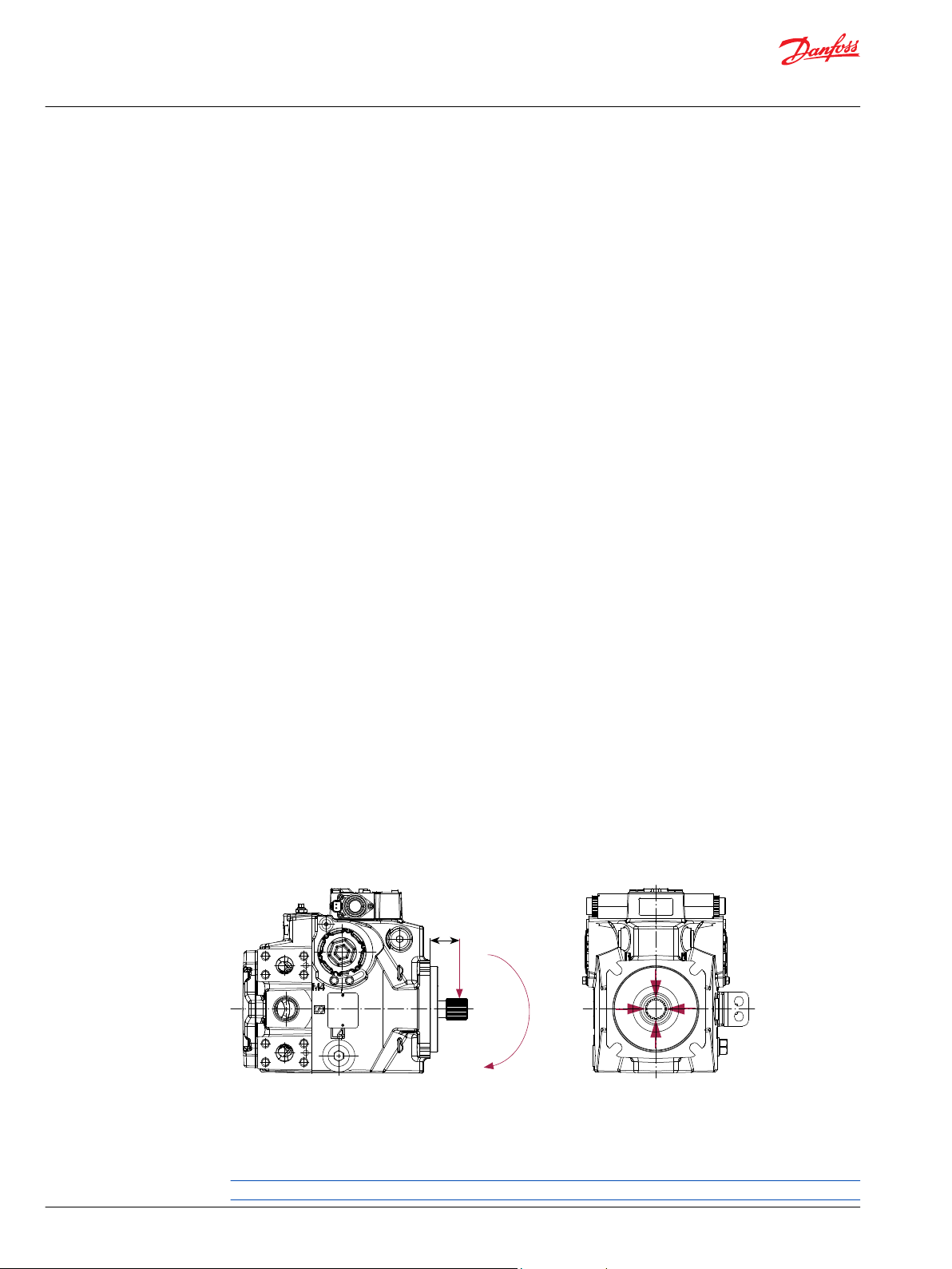
P003 318E
L
270° Re
Re
Me
180° Re
90° Re
0° Re
Basic Information
H1 Axial Piston Pumps, Single and Tandem
System design parameters
Bearing loads and life
Bearing life is a function of speed, system pressure, charge pressure, and swashplate angle, plus any
external side or thrust loads. The influence of swashplate angle includes displacement as well as
direction. External loads are found in applications where the pump is driven with a side/thrust load (belt
or gear) as well as in installations with misalignment and improper concentricity between the pump and
drive coupling. All external side loads will act to reduce the normal bearing life of a pump. Other life
factors include oil type and viscosity.
In vehicle propel drives with no external shaft loads and where the system pressure and swashplate
angle are changing direction and magnitude regularly, the normal L20 bearing life (80 % survival) will
exceed the hydraulic load-life of the unit.
In non propel drives such as vibratory drives, conveyor drives or fan drives, the operating speed and
pressure are often nearly constant and the swashplate angle is predominantly at maximum. These drives
have a distinctive duty cycle compared to a propulsion drive. In these types of applications a bearing life
review is recommended.
Applications with external shaft loads H1 pumps are designed with bearings that can accept some
external radial and thrust loads. When external loads are present, the allowable radial shaft loads are a
function of the load position relative to the mounting flange, the load orientation relative to the internal
loads, and the operating pressures of the hydraulic unit. In applications where external shaft loads cannot
be avoided, the impact on bearing life can be minimized by proper orientation of the load. Optimum
pump orientation is a consideration of the net loading on the shaft from the external load, the pump
rotating group and the charge pump load.
In applications where the pump is operated such that nearly equal amounts of forward vs. reverse
•
swashplate operation is experienced; bearing life can be optimized by orientating the external side
load at 0° or 180° such that the external side load acts 90° to the rotating group load (for details see
drawing below).
In applications where the pump is operated such that the swashplate is predominantly (> 75 %) on
•
one side of neutral (e.g. vibratory, conveyor, typical propel); bearing life can be optimized by
orientating the external side load generally opposite of the internal rotating group load. The direction
of internal loading is a function of rotation and system port, which has flow out. Tables are available
in the Controls section of each H1 size specific technical information that illustrates the flow out port
as a function of pump rotation and energized EDC solenoid.
H1 pumps are designed with bearings that can accept some thrust load such that incidental thrust
•
loads are of no consequence. When thrust loads are anticipated the allowable load will depend on
many factors and it is recommended that an application review be conducted.
Contact Danfoss for a bearing life review if external side loads are present.
Radial load position
Me = Shaft moment
L = Flange distance
Re = External force to the shaft
Allowable shaft loads and moments are shown for each size specific technical information.
40 | © Danfoss | December 2021 BC152886483968en-001001
Page 41

P005 275
L1
L2
L3
F2 F1
F3
Basic Information
H1 Axial Piston Pumps, Single and Tandem
System design parameters
Mounting flange loads
Adding tandem mounted auxiliary pumps and/or subjecting pumps to high shock loads may result in
excessive loading of the mounting flange. Applications which experience extreme resonant vibrations or
shock may require additional pump support. The overhung load moment for multiple pump mounting
may be estimated using the formula below:
Overhung load example
Estimating overhung load moments, max. and rated acceleration factors for some typical applications:
Rated load moment Shock load moment
MR = g • GR (W1L1 + W2L2 + ... + WnLn) N•m [lbf•in] MS = g • GS (W1L1 + W2L2 + ... + WnLn) N•m [lbf•in]
Variables:
g = Gravity 9.81 m/s²
GR = Calculation factor for rated (vibratory) acceleration. This factor depends on the application.
GS = Calculation factor for max. shock acceleration. This factor depends on the application.
W = Mass/Weight of pump, kg [lb]
L = Distance from mounting flange to pump center of gravity, m [in] (refer to Installation drawings.)
Allowable overhung load moment values are given for each size specific technical information. Exceeding
these values requires additional pump support.
Typical G loads for various applications
Application Calculation factor
Skid Steer Loader 8 15-20
Trencher (rubber tires) 3 8
Asphalt Paver 2 6
Windrower 2 5
Aerial Lift, Turf Care 1.5 4
Vibratory Roller 6 10
Rated (vibratory) acceleration GRMaximum (shock) acceleration G
S
Use these in the absence of specific data for a rough estimation.
©
Danfoss | December 2021 BC152886483968en-001001 | 41
Page 42

Basic Information
H1 Axial Piston Pumps, Single and Tandem
System design parameters
Shaft Torque for Splined Shafts
The rated torque of a flooded spline can increase to that of the maximum published rating. A flooded
spline would be indicative of a pump driven by a pump drive or plugged into an auxiliary pad of a pump.
Rated
torque
Maximum
torque
Shaft Torque for Tapered Shafts
Rated torque is based on the contact pressure between the shaft and hub surfaces with poor surface
is a measure of tooth wear and is the torque level at which a normal spline life of 2 x 10
shaft revolutions can be expected. The rated torque of a flooded spline can increase to
that of the maximum published rating. A flooded spline would be indicative of a pump
driven by a pump drive or plugged into an auxiliary pad of a pump.
Presumes a regularly maintained minimum level of lubrication via a moly-disulfide grease
in order to reduce the coefficient of friction and to restrict the presence of oxygen at the
spline interface. It is also assumed that the mating spline has a minimum hardness of Rc
55 and full spline depth.
The rated torque is proportional to the minimum active spline length.
is based on torsional fatigue strength considering 100.000 full load reversing cycles.
However, a spline running in oil-flooded environment provides superior oxygen
restriction in addition to contaminant flushing.
Maintaining a spline engagement at least equal to the pitch diameter will also maximize
spline life. Spline engagements of less than ¾ pitch diameter are subject to high contact
stress and spline fretting.
contact areas. With an increased quality of the contact areas, the contact pressure
between the shaft and hub is increased and allows higher torque to be transmitted.
When a key is used for orientation of the hub on the shaft in conjunction with poor
quality contact surfaces, the transmitted torque will drop significantly. This is due to the
key carrying the torque, which limits the shaft torque carrying capability.
9
Maximum
torque
42 | © Danfoss | December 2021 BC152886483968en-001001
is based on an ideal contact area of 100 % and the retaining nut properly torqued. This
allows for the highest contact pressure between the shaft and the hub.
Page 43

2. stage 1. stage
3. stage
P003 333E
Me1 for the second pump
Me3 for the next pump
Me1 for the first pump
Me input torque
C
Basic Information
H1 Axial Piston Pumps, Single and Tandem
System design parameters
Shaft availability and torque ratings
Multiple pump installations must consider the loads from the entire pump stack and all torques are
additive. Charge pumps loads must also be included.
Caution
Ensure requirements do not exceed shaft torque ratings. Torque required by auxiliary pumps is additive.
Alignment between the mating spline’s Pitch Diameters is another critical feature in determining the
operating life of a splined drive connection. Plug-in, or rigid spline drive installations can impose severe
radial loads on the shafts.
The radial load is a function of the transmitted torque and shaft eccentricity. Increased spline clearance
will not totally alleviate this condition; BUT, increased spline clearance will prevent mechanical
interference due to misalignment or radial eccentricity between the pitch diameters of the mating
splines. Spline life can be maximized if an intermediate coupling is introduced between the bearing
supported splined shafts.
Rated and maximum torque ratings for each available shaft is shown in the H1 size specific technical
information.
©
Danfoss | December 2021 BC152886483968en-001001 | 43
Page 44

Basic Information
H1 Axial Piston Pumps, Single and Tandem
System design parameters
Minimizing System Noise
Noise is transmitted in fluid power systems in two ways: as fluid borne noise, and structure borne noise.
System lines and pump mounting can amplify pump noise.
Fluid-borne
noise
Structure
born noise
Follow the suggestions below to minimize noise in your application:
Use flexible hoses
•
Limit system line length
•
If possible, optimize system line position to minimize noise
•
If you must use steel plumbing, clamp the lines
•
If you add additional support, use rubber mounts
•
Test for resonants in the operating range; if possible avoid them
•
(pressure ripple or pulsation) is created as pumping elements discharge oil into the
pump outlet. It is affected by the compressibility of the oil, and the pump’s ability to
transition pumping elements from high to low pressure. Pulsations travel through the
hydraulic lines at the speed of sound (about 1400 m/s [4600 ft/sec] in oil) until there is a
change (such as an elbow) in the line. Thus, amplitude varies with overall line length
and position.
is transmitted wherever the pump casing connects to the rest of the system. The way
system components respond to excitation depends on their size, form, material, and
mounting.
44 | © Danfoss | December 2021 BC152886483968en-001001
Page 45

Qe =
1000
Vg • n • η
v
(l/min)
Qe =
231
(US gal/min)
Vg • n • η
v
Me =
20 • π • η
m
Vg • ∆p
(N•m)
Me =
2 • π • η
m
Vg • ∆p
(lbf•in)
P
e
=
30 000
η
t
• n • p
=
600 •
Qe • ∆p
M
e
(kW)
P
e
=
198 000
η
t
• n • p
=
1714 •
Qe • ∆p
M
e
(hp)
Basic Information
H1 Axial Piston Pumps, Single and Tandem
System design parameters
Determination of Nominal Pump Sizes
Generally, the sizing process is initiated by an evaluation of the machine system to perform the necessary
work function. The following formulae can be used to determine the nominal pump size for a specific
application.
Metric System Inch System
Output flow
Input torque
Input power
Variables:
Vg = Displacement per rev.
pHP = High pressure
pNP = Low pressure
∆p = pHP – p
n = Input speed
ηv = Volumetric efficiency
ηm = Mechanical (torque) efficiency
ηt = Overall efficiency (ηv • ηm)
NP
SI units [US units]:
cm3/rev [in3/rev]
bar [psi]
bar [psi]
bar [psi]
min-1 (rpm)
©
Danfoss | December 2021 BC152886483968en-001001 | 45
Page 46

Danfoss
Power Solutions GmbH & Co. OHG
Krokamp 35
D-24539 Neumünster, Germany
Phone: +49 4321 871 0
Danfoss
Power Solutions ApS
Nordborgvej 81
DK-6430 Nordborg, Denmark
Phone: +45 7488 2222
Danfoss
Power Solutions (US) Company
2800 East 13th Street
Ames, IA 50010, USA
Phone: +1 515 239 6000
Danfoss
Power Solutions Trading
(Shanghai) Co., Ltd.
Building #22, No. 1000 Jin Hai Rd
Jin Qiao, Pudong New District
Shanghai, China 201206
Phone: +86 21 2080 6201
Products we offer:
Hydro-Gear
www.hydro-gear.com
Daikin-Sauer-Danfoss
www.daikin-sauer-danfoss.com
Cartridge valves
•
DCV directional control
•
valves
Electric converters
•
Electric machines
•
Electric motors
•
Gear motors
•
Gear pumps
•
Hydraulic integrated
•
circuits (HICs)
Hydrostatic motors
•
Hydrostatic pumps
•
Orbital motors
•
PLUS+1® controllers
•
PLUS+1® displays
•
PLUS+1® joysticks and
•
pedals
PLUS+1® operator
•
interfaces
PLUS+1® sensors
•
PLUS+1® software
•
PLUS+1® software services,
•
support and training
Position controls and
•
sensors
PVG proportional valves
•
Steering components and
•
systems
Telematics
•
Danfoss Power Solutions is a global manufacturer and supplier of high-quality hydraulic and
electric components. We specialize in providing state-of-the-art technology and solutions
that excel in the harsh operating conditions of the mobile off-highway market as well as the
marine sector. Building on our extensive applications expertise, we work closely with you to
ensure exceptional performance for a broad range of applications. We help you and other
customers around the world speed up system development, reduce costs and bring vehicles
and vessels to market faster.
Danfoss Power Solutions – your strongest partner in mobile hydraulics and mobile
electrification.
Go to www.danfoss.com for further product information.
We offer you expert worldwide support for ensuring the best possible solutions for
outstanding performance. And with an extensive network of Global Service Partners, we also
provide you with comprehensive global service for all of our components.
Local address:
Danfoss can accept no responsibility for possible errors in catalogues, brochures and other printed material. Danfoss reserves the right to alter its products without notice. This also applies to products
already on order provided that such alterations can be made without subsequent changes being necessary in specifications already agreed.
All trademarks in this material are property of the respective companies. Danfoss and the Danfoss logotype are trademarks of Danfoss A/S. All rights reserved.
©
Danfoss | December 2021 BC152886483968en-001001
 Loading...