

Page 1
Installation Manual
GX
Danfoss GX Heating Cables & Mats
Manuel d'installation
Câbles et tapis de chauffage Danfoss GX
Danfoss
BRINGING WARMTH TO LIFE
G
TM
Page 2

Table of Contents
Danfoss GX Snow Melting System ......................................................................................
Danfoss GX Cable/Mat ............................................................................................................
Warnings ......................................................................................................................................
General Installation Guidelines ............................................................................................
Sensor Installation ....................................................................................................................
Sensor Placement .....................................................................................................................
Installing the Heating Mat/Cable ........................................................................................
Concrete Installation ................................................................................................................
Asphalt Installation ..................................................................................................................
Stonework Installation.............................................................................................................
Danfoss Warranty ......................................................................................................................
Table des Matières
2
3
4
5
6
7
8
9
11
12
14
Fondeuse à neige Danfoss GX...............................................................................................
Câble/tapis Danfoss GX............................................................................................................
Mises en gar
de.........................................................................................................................
...
Lignes directrices générales d'installation........................................................................
Installation du détecteur.........................................................................................................
Placement du détecteur..........................................................................................................
Installation du tapis/câble de chauffage...........................................................................
Installation dans le béton........................................................................................................
Installation dans l'asphalte.....................................................................................................
Installation dans la maçonnerie............................................................................................
Garantie Danfoss........................................................................................................................
15
16
17
18
19
20
21
22
24
25
27
Copyright
2017
Danfoss
VIAPF222 05/17
TEL: 1-888-326-3677. FAX: 416-352-5981
1
Page 3
Danfoss GX Snow Melting System
Danfoss GX Snow Melting System
The GX Snow Melting System consists of the GX 850 Automatic Control Panel (ACP), heating
cables or heating mats and multiple digitally operated sensors which provide an economical
and efficient means of snow melting and ice protection. Built for outdoor use, the GX system
provides safety and peace of mind to homeowners and business owners alike
surfaces such as asphalt, concrete and paving tiles the Danfoss GX Snow Melting System is both
versatile and easy to install. The Danfoss GX Snow Melting System operates automatically by
digitally sensing moisture and temperature.
The GX System is embedded during the paving installation, such that some control and
accessories
It is recommended to install thermal insulation below the application of the heating cables or
mats. Improved performance and efficiency will decrease overall operating costs.
CAUTION!
It is important that this equipment is
with the proper sizing, installation, construction and operation of outdoor heating systems
and the hazards involved. The GX system is designed for outdoor ice and snow melting
applications only.
must also be installed at this time.
. Engineered for
only installed by qualified electricians who are familiar
Note!
The installation shall be in accordance with the manufacturer's instructions and national and
local electrical codes
. The installation shall be in accordance with Part 426, American National
Standard Institute / National Fire Protection Association (ANSI/NFPA70), National Electrical
Code (NEC) and Canadian Electrical Code (CEC), Part 1. You must use a ground fault
equipment protection (GFEP) device for outdoor areas.
Copyright
2017
Danfoss
VIAPF222 05/17
TEL: 1-888-326-3677
AX: 416-352-5981
. F
2
Page 4
Danfoss GX Cable/Mat
Danfoss GX snow melting cables are the basis of an electric snow melting system designed to ease
the snow removal process as well as lessen its environmental impact. The GX system is both
efficient and economical. It consists of twin conductor heating cables and a single point connection
with a 20’ (6m) power lead. Danfoss GX cables are CSA certified.
Snow melting cables/mats suitable for concrete, asphalt, pavers, and stonework
Ideal for driveways, parking lots, sidewalks, stairs, ramps, loading areas and bridges
o
o
Reduces the environmental impact of snow and ice removal by eliminating the use of fossil
fuel driven snow blowers, snowplows, rock salt and/or other chemicals
Silent, efficient, automatic and safe
Single point connection
Zero EMF’s
Genuine twenty year warranty
Danfoss GX Cable/Mat Specifications
Type:
Voltage:
Output:
Heating Element Size:
Mat
Cable
Power Lead
Bending Radius:
Cable Diameter:
Conductor Insulation:
Outer Insulation:
Max. Temperature:
Min. Installation Temp.:
Twin conductor
208, 240, 277, 347, 480, 600V
50W/sq.ft. (540W/m ) Cable 12W/ft
2
6.5’ (1.98 m) - 80’ (24.38 m) long x 2’ (0.61 m) wide
35’ - 545’ (10.7 - 166 m)
20’ (6.0 m)
Minimum 1.5” (3.8 cm)
1/4”(0.65 cm)
/
FEP Teflon
PVC
220°F (105ºC)
40°F (5ºC)
Copyright
2017
Danfoss
Connection (all voltages)
Phase - Black
Phase- White
Ground - Green
VIAPF222 05/17
TEL: 1-888-326-3677. FAX: 416-352-5981
3
Page 5
Warnings
Caution!
Is it important to read the instructions carefully before installing the Danfoss GX
Snow Melting System.
For outdoor installation only;
l
Never cut the black heating cable;
l
lExtreme care must be used to ensure the GX cables are not damaged when using sharp
tools, wheelbarrows, heavy machiner y and paving equipment, shovels, rakes, or other
implements. Avoid walking on the cables or mats during installation;
lIt is not recommended to install the Danfoss GX heating mats with a controller that
does not contain an integrated temperature limiter;
lThe GX mat or GX cable must be embedded in mortar or mortar mixture, concrete, sand
or similar material;
lThe power lead/heating cable connection and at least 1’ (30 cm) of the power lead
must be embedded in the paved surface;
lRemaining power lead should be run through the conduit
lThe power lead may be extended if required;
lDo not install the Danfoss GX cables in such a manner that two black heating
cables touch, cross or overlap;
Remember to always measure, verify and record the actual resistance throughout the
installation process:
1. Out of the box
2. After installation
3. Before pouring the sand/concrete/asphalt
4. After surface material application
Record these values in the
table on page 20 and on the warranty card, failure to do so
will void the warranty;
lMeasure the resistance between two live conductors as well as the resistance between
each conductor and the ground wire.
l Danfoss recommends using a megaohmmeter to test the insulation resistance.
lRemember to check that the supply voltage matches the voltage required for your
particular Danfoss GX product;
lRemember to place the labels as instructed in this manual;
l Metal structures or materials used for the support of or on which the Danfoss GX is
installed must be grounded in accordance with CSA Standard C22.1, Section 10 and the
NEC.
Please consult the Danfoss Electrical Heating Division for any other questions,
concerns
or advice.
Copyright
2017
Danfoss
VIAPF222 05/17
TEL:
1-888-326-3677
416-352-5981
FAX:
.
4
Page 6
General Installation Guidelines
Planning
It is recommended to sketch a plan of the layout for the heating system installation. Mat/cable
location, sensor placement, junction boxes, conduits and the location of drains and other
obstructions should be noted.
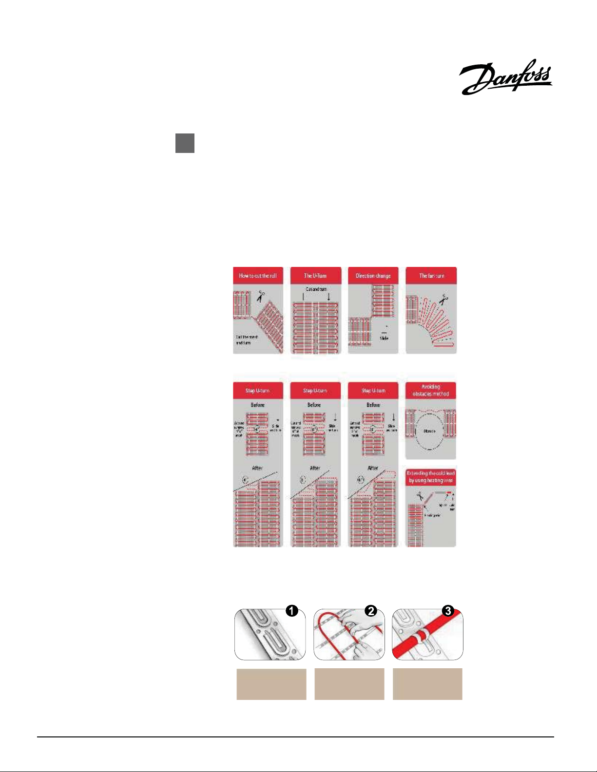
Mat Alterations
The GX heating mats can be altered to accommodate drains, obstructions or bends in the layout.
By carefully cutting the mat tape, many patterns
illustrates this.
and designs can be created The figure below
Copyright
2017
Danfoss
Free Cable and Cable Strapping
Should the Danfoss cable strapping be used for the GX cable, follow the instructions below for
ease of installation.
Attach the Danfoss
strapping to the
ground surface
(3’ apart)
VIAPF222 05/17
Place the GX cable
(3” standard
spacing)
Clip the GX cable
in place
TEL: 1-888-326-3677. FAX:
416-352-5981
5
Page 7
Installing a Feeder Cable
(For use with Gx850 and/or ground sensors, not applicable when using DS-2B.)
A feeder cable for a sensor may be needed. A 50’ (15m) cable is supplied with each sensor.
Approx. 1.5’ (0.5m) of this cable should be coiled inside the bottom of the sensor tube. The
remaining cable may be lengthened. The feeder cable must be a four wire cable.
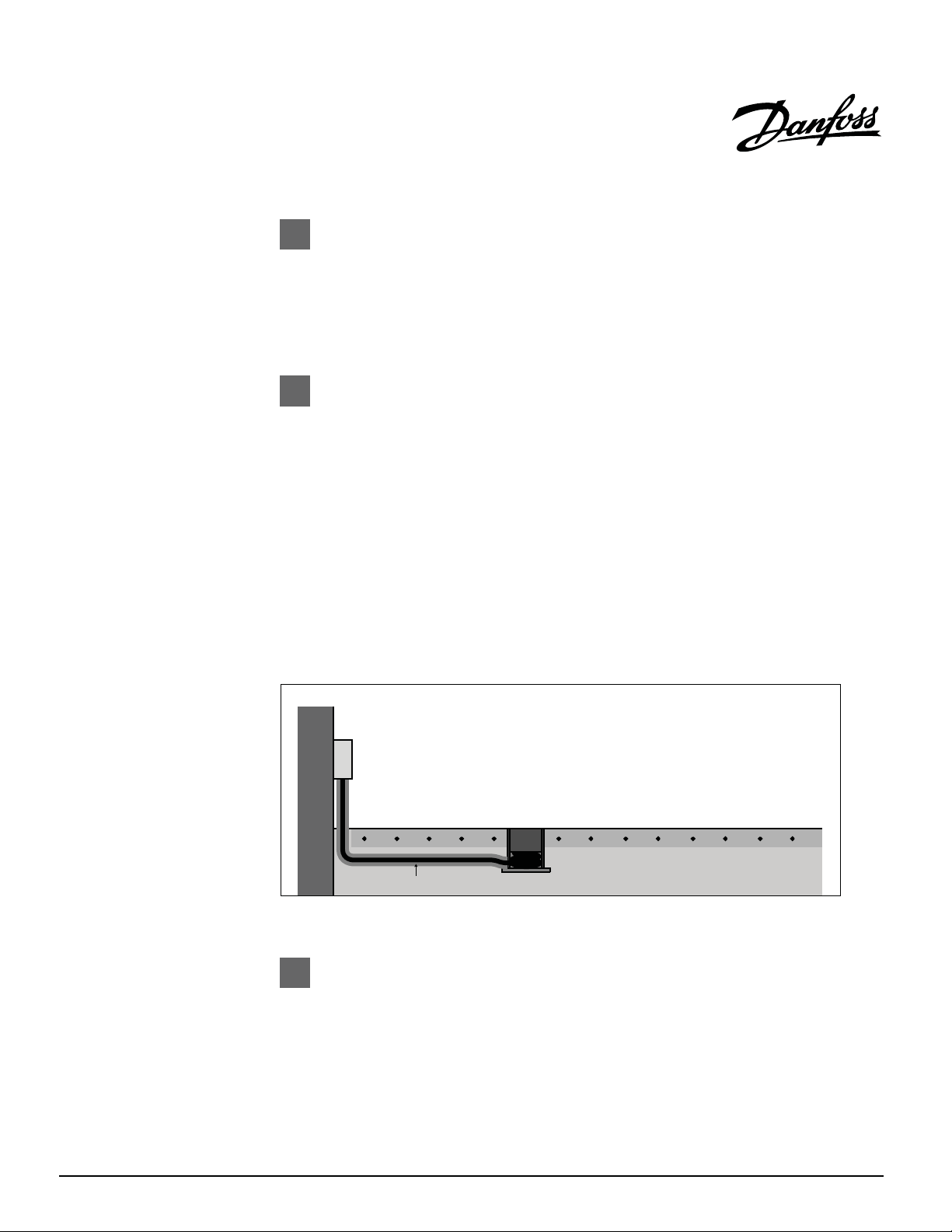
Installing a Sensor and a Conduit
The sensor and the conduit may be installed in connection with the actual construction work
and connected at a later date. The following applies for all types of installations:
1. Ensure that the conduit is sealed when the concrete is poured.
2. The conduit must be positioned so that it is flush with the surrounding terrain.
must be placed so that the upper brass surface is horizontal.
3. The base below the tube must be hard, e.g. a concrete tile, in order to ensure that the sensor is
not pushed into the ground if for example a vehicle runs over it. The tube is designed
mounted on a plate using the two screw holes inside the conduit.
4. A metal/plastic pipe, through which the sensor cable may be passed, should be run as far as
the sensor conduit.
5. Coil approx. 1.5’ (0.5m) of the sensor cable inside the conduit.
6. Place the sensor inside the tube until
resting on the internal collar inside the conduit. The sensor may be extracted at a later date
using the two holes found around the edge of the sensor conduit. The grooves on the outside of
the sensor should correspond
with the holes in the conduit.
it is horizontally flush with the edge of the conduit and
The sensor
to be
Installation in Asphalt
The temperature must not exceed F °C) around the sensor/tube. A wooden block or
similar place holder may be used in the area where the tube/sensor can be placed subsequently.
The installation pipe used for the sensor cable should, in that case, be a metal tube that can
withstand high temperatures.
Copyright
2017
Danfoss
Installation of conduit with sensor cable
176° (80
VIAPF222 05/17
TEL: 1-888-326-3677. FAX:
416-352-5981
6
Page 8
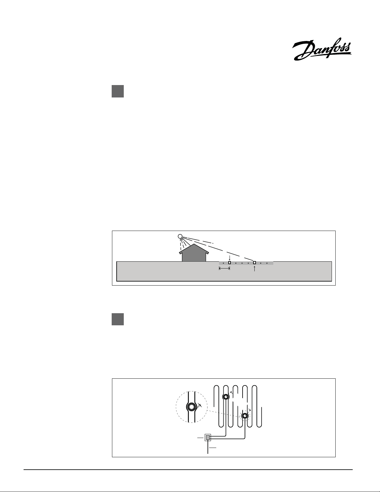
Placement of Ground Sensors
Correct placement of the sensor(s) is important for the system to work as
intended. Some basic guidelines follow:
The number of ground sensors:
1. The more sensors added to the system the better the performance.
2. The basic principle is to place one sensor where the snow/ice will appear first (for fast
detection) and one sensor where the snow/ice will disappear
not obvious just place the sensors as far apart from each other as possible.
3. With only one sensor you will have to decide what is most impor tant:
a) fast detection and activation of the system or
b) securing a complete melting of all snow/ice. A
in terms of detection and activation than a two sensor ground system, where one sensor
measures the ground temperature and the other sensor measures the moisture.
4. With more than two sensors it is possible to cover problem spots where snow usually is not
detected or where snow is not completely melted when the system stops.
last (for complete melting). If it is
one sensor ground system will be slower
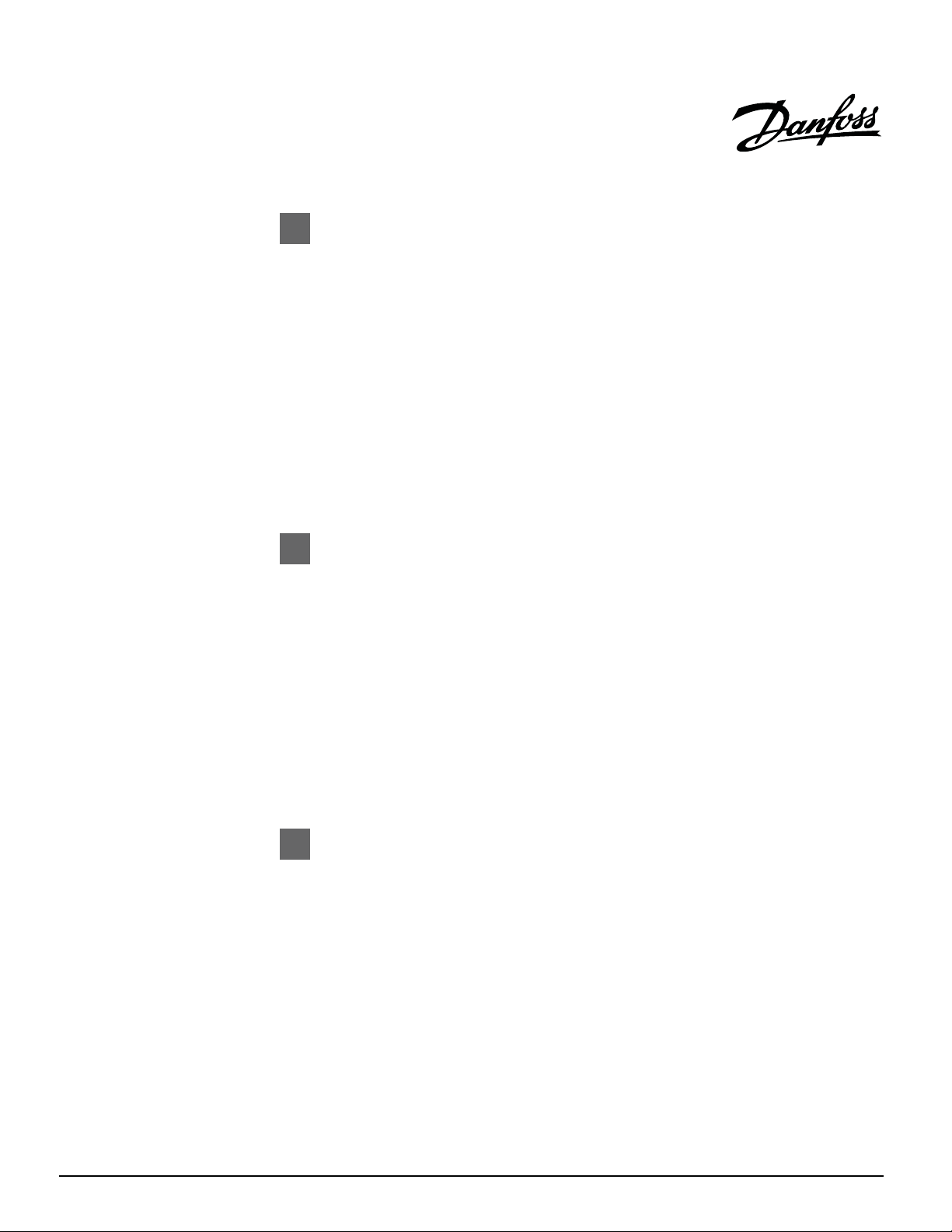
Placement of Individual Ground Sensors
1. The sensor must be placed within the heated area and at least 3.3’ (1 m)
from the edge of the area, if possible.
2. The sensor must be placed in between the heating cables - a distance
of minimum 0.4” (1 cm) should be maintained between the sensor tube
and the heating cable.
3. There
must be a distance of minimum 3.3ft. (1 m) between the two sensors.
0.4” (1cm)
Junction box
SensorMin. 3 ft.
min 3.3ft.
(1m)
Feeder cable
Copyright
2017
Danfoss
VIAPF222 05/17
TEL:
1-888-326-3677
AX: 416-352-5981
F
.
7
Page 9
Installing the heating mat
Begin by fastening the heating mat to the mesh reinforcement using tie-wraps or cable strapping.
Do not fix the heating cable of the mat in such a way that it is compressed or strained - it must be
able to move. Unroll the mat up to the point at which it is to be flipped and turned. Use the figure on
page 5 to alter the mat.
Cut the tape using scissors
already unrolled mat. Do not cut the cable! The cable can be carefully detached from the tape
and then placed as free cable. This feature can be very useful for curves and around drains or other
obstructions.
Labels:
Labels 2E or F are to be placed at the switchboard
Labels 3E and F are to be placed in the room or area where the heating mat/cable is installed
and rotate the mat so that it can be unrolled to cover the area next to the
Installing the heating cable
The GX cable must be laid out with even spacing over the entire area to be heated. To ensure an
accurate and easy method of installing the GX cable it is recommended to use Danfoss cable
strapping. Attach the cable strapping to the rebar or other supporting structure using tie-wraps.
The strapping should be laid perpendicular to the direction
strapping 3’ (75cm) apart. Secure the heating cable to the cable strapping at the correct center-tocenter distance. Do not secure the cable too tightly as this may damage the cable. If not using the
cable strapping, affix the heating cable to the rebar or wire mesh using tie wraps.
Labels:
Labels 2E or F are to be placed at the switchboard
Labels 3E and F are to be placed in the room or area where the heating mat/cable is installed
Center-to-Center (C-C) distance
the cable will be unrolled. Space the
Copyright
2017
Danfoss
The C-C distance is the distance between the GX cables (GX mats have a preset C-C distance).
Standard spacing for 50W/sq.ft. (540W/m ) is 3” (7.5 cm). In a typical application the C- C distance
should not exceed 4” and be less than 3” if the cables are installed as part of a total heating system.
If the C-C distance is higher, cold spots may form on the surface and incomplete melting may occur.
VIAPF222 05/17
2
TEL: 1-888-326-3677
. FAX: 416-352-5981
8
Page 10

Concrete Installation
When installing Danfoss GX heating cables the following should be observed:
Begin installation as close as possible to electrical supply source. The heating cable
Insulation can be installed to improve efficiency of the heating system.
must not be cut or shortened or exposed to strain in the areas of the cold tail/heating
cable coupling.
When placing the sensors
please see page 7.
Special care should be taken not to damage the heating cables with tools and
machinery during the installation and application of the surface material.
Ensure that all sharp stones and debris are removed from the area where the heating
cables are going to be installed.
Should the cable become
damaged during the installation process it is helpful to know
the location of the cold tail/heating cable connection. Take a picture or sketch to show
where the connection/end cap is in case a fault needs to be found.
Connection of the heating cable must be carried out by an authorized electrician.
Note the maximum
output allowed for your installation. Do not exceed it. Contact
your local Danfoss GX dealer for questions/concerns.
Make sure the cable is not subjected to excess tension or strain. It should not cross an
expansion joint. Where expansion joints are present, separate mats/cables should be
used.
The heating
cable braid must be grounded in accordance with local electrical codes.
Make sure when the cable is laid it is not pushed into the insulating material.
Ensure no air pockets exist in the surface material as this can result in damage to the
cable and limit the heat transfer.
An upstream disc
onnect must be installed to ensure a means of de-energizing the
cable or mat.
Copyright
2017
Danfoss
At low temperatures, the heating cable stiffens and may be difficult to work with.
To overcome this, connect the cable to the mains for a brief period of time. Ensure the
cable is fully
rolled out when this is done.
VIAPF222 05/17
TEL: 1-888-326-3677
. FAX: 416-352-5981
9
Page 11

Concrete Installation (continued)
The cables are normally covered by 2 inches of concrete. A thicker surface may be required
depending on the pour and application.
Make sure that the free cable is fastened at intervals of minimum 3’ (45 cm), as the
concrete might move the cable when it is poured.
The concrete mixture must not contain sharp stones as these may damage the cable.
The concrete should be allowed to set for 30 days before the heating cables are turned on.
It is not recommended for the GX mat or cable to cross an expansion joint.
CONCRETE
GX HEATING MAT/CABLE
CRUSHED STONE
AND/OR INSULATION
GROUND
Copyright
2017
Danfoss
VIAPF222 05/17
TEL:
1-888-326-3677
. FAX: 416-352-5981
10
Page 12

Asphalt Installation
When installing heating cables the following should be observed:
Begin installation as close as possible to electrical supply source. The heating cable
Install cables in a direction perpendicular to the direction that the paving rollers will
When placing the sensors please see page 7.
Special care should be taken not to damage the heating cables with tools and
must not be cut or shortened or exposed to strain in the areas of the cold tail/heating
cable coupling.
prevent straining or damaging the cable.
pass to
Insulation can be installed to improve efficiency of the heating system.
machinery during the installation and application of the surface material.
Ensure that all sharp stones and debris are r
cables are
going to be installed.
emoved from the area where the heating
Should the cable become damaged during the installation process it is helpful to know
the location of the cold tail/heating cable connection. Take a picture or sketch to show
where the connection/end cap is in case a fault needs to be found.
Connection
of the heating cable must be carried out by an authorized electrician.
Note the maximum output allowed for your installation. Do not exceed it. Contact
your local Danfoss GX dealer for questions/concerns.
Make sure the cable is not subjected to excess tension or strain. It should not cross an
expansion joint.
The heati
ng cable braid must be grounded in accordance with local electrical codes.
Make sure when the cable is laid it is not pushed into the insulating material.
Ensure no air pockets exist in the surface material as this can result in damage to the
cable and limit the heat transfer.
n upstream disconnect must be installed to ensure a means of de-energizing the
A
cable or mat.
At low temperatures, the heating cable stiffens and may be difficult to work with.
To overcome this, connect the cable to the mains for a brief
period of time. Ensure
thecable is fully rolled out when this is done.
Copyright
2017
Danfoss
VIAPF222 05/17
TEL: 1-888-326-3677
. FAX: 416-352-5981
11
Page 13
Asphalt Installation (continued)
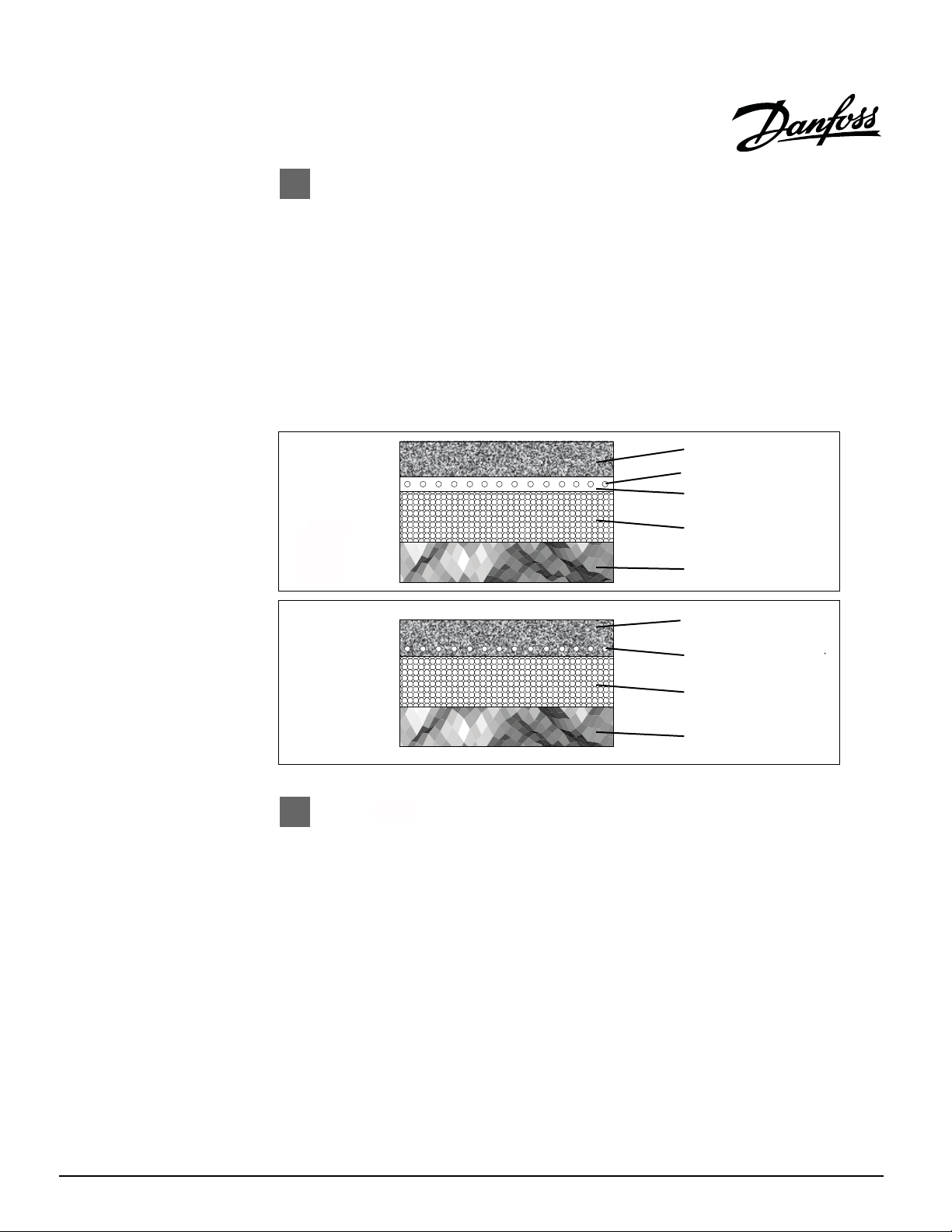
It is recommended to cover the cables with a layer of sand or concrete at least 1" (2.5 cm)
before the asphalt is applied to protect them from the heat of the asphalt. Use of sand or
concrete will ensure an effective and efficient heat transfer through the asphalt.
If using sand or concrete, allow the asphalt to cool to a temperature of 265°F (130°C)
maximum before pouring. If using without sand or concrete, allow asphalt to cool to
220°F/ (105°C) before pouring directly on mats/cables. Ground sensors/tubes should not
be exposed to temperatures above 80°C (176°F.)
The cables are normally covered by 2 inches of asphalt.
A perimeter of maximum 12” (30 cm) of asphalt should exist, unheated around the
embedded cables. This allows for adjustment of the paving surface edge without
damaging the heating cable.
The operating weight of the asphalt roller should not exceed 1000lbs.
MAT EMBEDDED IN
SAND/CONCRETE
MAT EMBEDDED
DIRECTLY IN ASPHALT
Stonework Installation
When installing heating cables the following should be observed:
Begin installation as close as possible to electrical supply source. The heating cable
must not be cut or shortened or exposed to strain in the areas of the cold tail/heating
cable coupling.
ASPHALT
GX HEATING MAT/CABLE
SAND/CONCRETE
EMBEDDING
CRUSHED STONE
AND/OR INSULATION
GROUND
ASPHALT
GX HEATING MAT/CABLE IN ASPHALT
(ALLOW ASPHALT TO COOL TO 220 F
BEFORE POURING ON MATS/CABLES)
CRUSHED STONE
AND/OR INSULATION
GROUND
Copyright
2017
Danfoss
Insulation can be installed to improve efficiency of the heating system.
When placing the sensors please see page 7.
Special care should be taken not to damage the heating cables with tools and
machinery
during the installation and application of the surface material.
Ensure that all sharp stones and debris are removed from the area where the heating
cables are going to be installed.
Should the cable become damaged during the installation process it is helpful to know
location of the cold tail/heating cable connection. Take a picture or sketch to show
the
where the connection/end cap is in case a fault needs to be found.
VIAPF222 05/17
TEL: 1-888-326-3677
. FAX: 416-352-5981
12
Page 14

Stonework Installation (continued)
Connection of the heating cable must be carried out by an authorized electrician.
Note the maximum output allowed for your installation. Do not exceed it. Contact
your local Danfoss GX dealer for questions/concerns.
Make sure the cable is not subjected to excess tension or strain. It should not cross an
expansion joint.
The heating
cable braid must be grounded in accordance with local electrical codes.
Make sure when the cable is laid, that it is not pushed into the insulating material.
Ensure no air pockets exist in the surface material as this can result in damage to the
cable and limit the heat transfer.
An upstream
disconnect must be installed to ensure a means of de-energizing the
cable or mat.
At low temperatures, the heating cable stiffens and may be difficult to work with.
To overcome this, connect the cable to the mains for a brief period of time. Ensure the
fully rolled out when this is done.
cable is
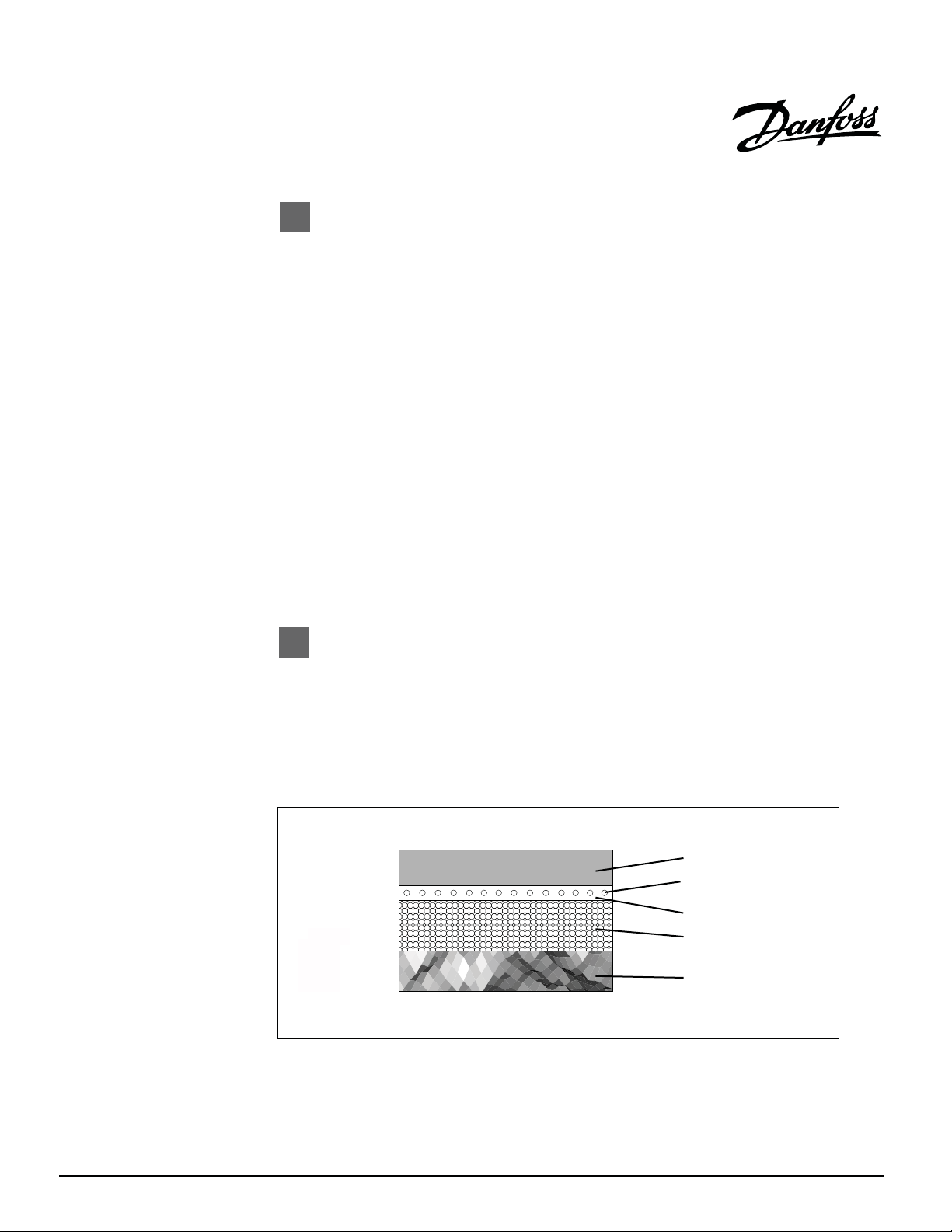
Special care must be taken not to damage the heating cables when they are installed
under bricks or tiles.
The area must be completely level and free of stones or other sharp objects.
The heating cable must be installed close to the bricks or tiles, typically in a layer of sand
(at least 1" (2.5 cm) under the brick).
Copyright
2017
Danfoss
3” max
VIAPF222 05/17
STONEWORK
GX HEATING MAT/CABLE
SAND
CRUSHED STONE
AND/OR INSULATION
GROUND
TEL: 1-888-326-3677
. FAX: 416-352-5981
13
Page 15

DANFOSS EXTENDED WARRANTY
For a period of
cable/mat is free from defects in material, design and workmanship. The extended warranty is only valid
if the warranty certificate has been properly completed and mailed, and the installation is in accordance
with the installation instructions.
The defective Danfoss GX cable has to be inspected by or submitted to Danfoss or an authorized Danfoss
GX dealer. Failure to comply with all of the foregoing will void this extended warranty. Danfoss will, when
the customer has documented that a defect in the Danfoss GX was present at the date of delivery, repair or
supply a new Danfoss GX at Danfoss’ option. All claims shall be made within the extended warranty period.
Danfoss shall not be liable for any claims made later than ten years from date of purchase.
Danfoss shall not be liable for any consequential and secondary costs or damages linked to the defect or
replacement of the Danfoss GX. Danfoss will be liable for any costs related to the dismantling of defective
product and the installation of a new product; however such liability is limited to the amount of five (5)
times the initial product costs for each damage/case.
THE FOREGOING WARRANTY IS EXPRESSLY IN LIEU OF ALL OTHER WARRANTIES, EXPRESS OR
IMPLIED, ON THE PART OF DANFOSS. DANFOSS DISCLAIMS ANY WARRANTY, EXPRESS OR IMPLIED,
OF MERCHANTABILITY OR FITNESS FOR A PARTICULAR PURPOSE. DANFOSS NEITHER ASSUMES
NOR AUTHORIZES ANY OTHER PERSON, FIRM OR CORPORATION TO ASSUME FOR IT ANY OTHER
LIABILITY IN CONNECTION WITH SALE OR PRODUCT. DANFOSS SHALL NOT BE HELD RESPONSIBLE
FOR DAMAGE TO PERSON OR PROPERTY, CONSEQUENTIAL LOSS, LOSS OF PROFIT, LOSSES ON
GOODS IN STORE, OR THE LIKE WHICH MIGHT ARISE OUT OF THE FAILURE OF THE EQUIPMENT
DELIVERED, IRRESPECTIVE OF THE CAUSE (INCLUDING FAULTY MANUFACTURE).
twenty (20) years from the date of purchase Danfoss warrants that the Danfoss GX
Copyright
How to claim this warranty
Contact the company's Customer Ser vice
department and provide the following
information:
1) Nature of the manufacturing defect
2) Date of purchase and, if already
installed, date of installation
3) If installed, name of electrician and
flooring installer
4) Resistance readings taken by installer
5) Proof of purchase and serial number
from product label
Our Customer Service department will provide
you with an authorization number and advise you
on the next steps to complete your warranty
claim.
2017
Danfoss
VIAPF222 05/17
Disclaimer:
This warranty gives you specific legal rights and you may
also have some legal rights which may vary from state to
state or province to province. Danfoss hereby disclaims,
and it is as a condition of the sale, that there are no implied
warranties. Some states and provinces do not allow
limitations on an implied warranty so the above limitation
may not apply to you.
Manufacturer:
Mail:
Phone:
Fax:
Danfoss Inc.
6711 Mississauga Rd.,
Suite 306
Toronto, ON
L5N
2W3
1-866-676-8062
416-352-5981
TEL: 1-888-326-3677
. FAX: 416-352-5981
14
Page 16

Fondeuse à neige Danfoss GX
Fondeuse à neige Danfoss GX
La fondeuse à neige GX consiste en un panneau de commande automatique GX 850, des câbles
ou tapis de chauffage et des détecteurs multiples à fonctionnement numérique qui fournissent
une façon économique et efficace de faire fondre la neige et une protection contre la glace. Bâtie
en vue d'une utilisation à l'extérieur,
d'esprit, tant aux propriétaires de maison qu'aux entrepreneurs. Conçue pour une utilisation
avec l'asphalte, le béton et les dalles, la fondeuse à neige Danfoss GX est à la fois polyvalente et
facile à installer. Elle fonctionne automatiquement en détectant
température.
Le dispositif GX est posé lors de l'installation du revêtement de sol. Il faut donc poser certaines
commandes et accessoires à ce moment.
Il est recommandé d'installer l'isolation thermique sous les câbles ou tapis de chauffage. Le
rendement et l'efficacité accrus permettront une réduction des coûts de fonctionnement.
la fondeuse à neige GX procure sécurité et tranquillité
numériquement l'humidité et la
MISE EN
Il est important de faire installer cet équipement par un électricien qualifié qui connaît les
dimensions, l'installation, la construction et le fonctionnement d'appareils de chauffage
extérieurs et les risques associés. L'appareil GX a été conçu uniquement aux fins d'utilisation à
l'extérieur, pour faire fondre la neige et la glace.
Nota!
Lors
électriques nationaux et locaux. Il est nécessaire de respecter la partie 426 de l'American
National Standard Institute / National Fire Protection Association (ANSI/NFPA70), le Code
national de l'électricité et le Code canadien de l'électricité, partie 1. V
dispositif de protection contre les défauts de terre et un dispositif de courant résiduel pour
l'extérieur.
GARDE!
de l'installation, il faut respecter les instructions du fabricant de même que les codes
ous devez utiliser un
Copyright
2017
Danfoss
VIAPF222 05/17
TEL: 1-888-326-3677. F
AX: 416-352-5981 15
Page 17

Câble/tapis Danfoss GX
Les câbles de fonte de neige Danfoss GX sont à la base de cett
fondeuse à neige électrique
e
conçue pour faciliter le processus d'enlèvement de neige et de réduire son impact sur
l'environnement. L'appareil GX est à la fois efficace et économique. Il consiste en des câbles de
chauffage conducteurs doubles et présente un seul point de connexion avec fil électrique de 6 m
(20 pi). Les câbles
·Câbles/tapis de fonte de neige pouvant être utilisés avec du béton, de l'asphalte, des
pavés et la maçonnerie (si la température de l'asphalte dépasse 105 C/220 F, il faut
Danfoss sont homologués CSA.
oo
o
o
insérer les câbles dans du sable).
·Idéal pour les entrées, les terrains de stationnement, les trottoirs, les escaliers, les
rampes, les aires de chargement et les ponts.
·Réduit l'impact sur l'environnement de l'enlèvement de la neige et de la glace en
éliminant l'utilisation des souffleuses
des charrues à neige qui utilisent un combustible
,
fossile et l'utilisation de sel blanc et/ou d'autres produits chimiques.
·Fonctionnement sûr, silencieux, efficace et automatique
·Point de connexion unique
·Champ électromagnétique nul
Spécifications des câbles et tapis Danfoss GX
Type:
Tension :
Sortie :
Dimensions des éléments
de chauffage : Tapis
Câble
Fil de courant
Rayon de la courbure:
Diamètre des câbles :
Isolation des conducteurs :
Isolation extérieure :
Température max. :
Temp. d'installation min.
Conducteur double
208, 240, 277, 347, 480, 600V
540 W/m (50 W/pi ca) – câble 120W/pi
2
1,98 m (6,5 pi – 24,38 m (80 pi) de longueur x 0,61 m
(2 pi) de largeur
10,7 m - 166 m (35 pi – 545 pi)
6 m (20 pi)
Minimum 3,8 cm (1,5 pi)
0,65 cm (¼ po)
Téflon FEP
PVC
oo
105 C (220 F)
oo
5 C (40 F)
Copyright
2017
Danfoss
Connexions (toutes tensions)
Phase - Noire
Phase- Blanche
Terre - Verte
VIAPF222 05/17
TEL: 1-888-326-3677. F
AX: 416-352-5981 16
Page 18
Mises en garde
Attention!
Il est important de lire les instructions avec soin avant d'installer la fondeuse à neige
Danfoss GX.
·Ce dispositif a été conçu en vue d'une installation à l'extérieur seulement.
·Ne coupez jamais le câble de chauffage noir.
·Il faut faire très attention de ne pas endommager les câbles du GX avec les outils
tranchants
pelles, les râteaux et les autres accessoires. Évitez de marcher sur les câbles ou
tapis pendant l'installation.
·Il n'est pas recommandé d'installer les tapis de chauffage Danfoss GX avec une
commande ne comportant pas un dispositif intégré de limitation de la
tempéra
·Le tapis ou câble GX doit être intégré au mortier ou au mélange de mortier, au
béton, au sable ou à un matériau semblable.
·Il faut que la connexion du fil de courant et du câble de chauffage et au moins
30 cm (1 pi) du fil de cour
, les brouettes, la machinerie lourde, l'équipement de pavement, les
ture.
ant soient intégrés à l'intérieur du pavement.
·Le reste du fil de courant doit passer dans le conduit.
·Le fil de courant peut être allongé au besoin.
·N'installez pas les câbles Danfoss GX de façon que deux câbles de chauffage
noirs se touchent, se croisent ou se chevauchent.
N'oubliez pas de t
au long du procédé d'installation :
1. En sortant le dispositif de la boîte;
2. Après l'installation;
3. Avant de verser le sable, le béton ou l'asphalte;
4. Suite à la pose du matériau de surface;
Consignez les valeurs obtenues sur le tableau figurant à la page 20 et sur la carte
de garantie. Le non-respect de cette consigne annulera la garantie.
·Mesurez la distance entre les deux conducteurs chargés ainsi que la résistance
entre chaque conducteur et le fil de mise à la terre.
·N'oubliez pas de vous assurer que la tension d'alimentation est la même que la
tension que r
·N'oubliez pas d'apposer les étiquettes tel qu'indiqué dans le présent manuel.
·Les structures ou matériaux métalliques utilisés pour le soutien ou l'installation du
Danfoss GX doivent être mis à la terre, conformément à la norme C22.1, article 10
de la CSA et au Code na
oujours mesurer, vérifier et consigner la résistance réelle, tout
equiert votre produit Danfoss GX.
tional de l'électricité.
Copyright
2017
Danfoss
VIAPF222 05/17
TEL: 1-888-326-3677. FAX: 416-352-5981 17
Page 19

Lignes directrices générales d'installation
Planification
Il est recommandé de tracer un plan de l'installation du système de chauffage. Prenez en note
l'emplacement du tapis ou des câbles, du détecteur, des boîtes de connexion, des conduits, des
drains et des obstructions.
Modifications des tapis
Les tapis de chauffage GX peuvent être modifiés pour s'adapter aux drains, aux obstructions et
aux courbes du plan d'implantation. On peut créer
découpant soigneusement le ruban du tapis. Voyez les illustrations ci-dessous.
Comment couper
le rouleau
Virage en U
Coupez et tournez
un grand nombre de dessins et motifs en
Changement de
direction
Virage en éventail
Coupez le treillis
et tournez
Étape de virage en U
Avant
Coupez
et enlevez
4 po de
treillis
Après
Faites
glisser et
tournez
Étape de virage en U
Avant
Coupez
et enlevez
6 po de
treillis
Après
Faites
glisser et
tournez
Faites
glisser
Étape de virage en U
Avant
Coupez
et enlevez
8 po de
treillis
Après
Faites
glisser et
tournez
Façon d'éviter
les obstacles
Raccord
Fil de chauffage
Bout
froid
Câble gratuit et fixation des câbles avec courroies
Si vous fixez le câble GX avec une courroie Danfoss, suivez les instructions ci-dessous qui
facilitent l'installation.
Copyright
2017
Danfoss
1.Fixez la courroie de
fixation Danfoss au sol
(3 pi de distance).
VIAPF222 05/17
2. Placez le câble GX
(espace standard
de 3 po).
3. Fixez le câble
GX en place.
1-888-326-3677. FAX: 416-352-5981 18
TEL:
Page 20

Installation d'un câble d'alimentation
(Pour utilisation avec le Gx850 et/ou des détecteurs au sol, ne peut s'appliquer au DS-2B.)
Il pourrait s'avérer nécessaire d'utiliser un câble d'alimentation pour détecteur. Un câble de 15 m
(50 pi) est fourni avec chaque détecteur. Il faut enrouler environ 0,5 m (1,5 pi) de ce câble dans la
partie inférieure du tube du détecteur. Le reste du câble peut être allongé. Le câble
d'alimentation doit être un câble à quatre fils.
Installation de détecteur et du conduit
On peut installer le détecteur et le conduit en association avec les travaux de construction et les
brancher à une date ultérieure. Les dispositions suivantes s'appliquent à tout type d'installation :
1. Assurez-vous que le conduit est scellé au moment du versement du béton.
2. Le conduit doit être placé de sorte à être à égalité avec le terrain voisinant. Le
détecteur
laiton.
3. La base sous le tube doit être dure (carreau en béton) de façon à s'assurer que le
détecteur n'est pas enfoncé dans le sol lors du passage d'une voiture par exemple. Ce
tube
du conduit.
4. Un tuyau en métal ou en plastique, par lequel passe le câble du détecteur, doit aller
aussi loin que le conduit du détecteur.
5. Enroulez environ 0,5 m (1,5 pi) du câble du détec
6. Placez le détecteur à l'intérieur du tube jusqu'à ce qu'il soit à égalité à l'horizontale
avec le bord du conduit et qu'il repose sur le col interne à l'intérieur du conduit. Le
doit être placé de façon à mettre à l'horizontale la surface supérieure en
est conçu pour être monté sur une plaque grâce aux deux trous à vis à l'intérieur
teur dans le conduit.
Installation dans l'asphalte
La température autour du détecteur/tube ne doit pas dépasser 80 C (176 F). Vous pouvez
mettre un bloc de bois ou un autre dispositif semblable là où le tuyau ou détecteur sera placé
par la suite. Le tuyau d'installation utilisé pour le câble de détecteur doit alors être fait de métal
pouvant supporter les températures élevées.
Copyright
2017
Danfoss
Installation de conduit avec câble de détecteur
VIAPF222 05/17
oo
1-888-326-3677. FAX: 416-352-5981 19
TEL:
Page 21

Placement du détecteur au sol
Il est important de placer les détecteurs correctement en vue d'un fonctionnement approprié.
Certaines lignes directrices de base sont décrites ci-dessous.
Nombre de détecteurs au sol
1. Plus il y a de détecteurs, mieux sera le rendement.
2. Le principe de base consiste à placer un détecteur là où la neige ou la glace apparaîtra
en premier (pour permettr
glace disparaîtra en dernier (pour permettre une fonte complète). Si cela s'avère
difficile à établir, placez les détecteurs aussi loin l'un de l'autre que possible.
e une détection rapide) et un détecteur où la neige ou la
3. Si vous n'utilisez qu'un détecteur, vous devrez décider de ce qui est le plus impor
entre :
a) une détection et une activation rapides du dispositif; et
b) assurer la fonte complète de toute la neige ou glace. Un dispositif à un seul
détecteur est plus lent qu'un dispositif à deux détecteurs en ce qui a trait à la
détection et à l'activation, car un des deux détecteurs mesure la température
au sol alors que l'autre mesure l'humidité.
Placement du détecteur au sol individuel
1. Le détecteur doit être placé à l'intérieur de l'aire de chauffage et à au moins 1 m (3 pi 3
po) du bord de la surface, si possible.
2. Le détecteur doit être placé entre les câbles de chauffage. Une distance d'au moins 1
cm (0,4 po) doit être main
tenue entre le tube du détecteur et le câble de chauffage.
Min. 3 pi
Détecteur
SensorMin. 3 ft.
Min. 3 ft.
tant
Copyright
2017
Danfoss
3. Il doit y avoir une distance d'au moins 1 m (3 pi 3 po) entre les deux détecteurs.
Min. 1 m
1 cm (0,4 po)
Boîte de connexion
VIAPF222 05/17
(3 po pi 3)
Câble d'alimentation
TEL: 1-888-326-3677. F
AX: 416-352-5981 20
Page 22

Installation du tapis de chauffage
Commencez en fixant le tapis de chauffage à l'armature en treillis au moyen des attaches ou des
courroies de câble. Ne fixez pas le câble de chauffage de façon à le comprimer ou à l'allonger – il
doit pouvoir bouger. Déroulez le tapis jusqu'à l'endroit où il faut le tourner ou l'inverser. Ayez
recours à
Coupez le ruban avec des ciseaux et tournez le tapis de façon à pouvoir le dérouler pour couvrir
la surface à côté du tapis déjà déroulé. Ne coupez pas le câble! On peut détacher délicatement
le câble du ruban et le placer comme câble libre
pour faire le tour de drains ou d'autres obstructions.
Étiquettes
Placez les étiquettes 2E ou F sur le tableau de contrôle.
Les étiquettes 3E et F doivent être placées dans la pièce ou dans le lieu où on installe le tapis ou
câble de chauffage.
l'illustration à la page 5 pour modifier le tapis.
Installation du câble de chauffage
Le câble GX doit être disposé de façon uniforme sur toute la surface à chauffer. Pour assurer une
installation correcte et facile du câble GX, il est recommandé d'utiliser les courroies de câble
Danfoss. Fixez les courroies à la barre d'armature ou à une autre structure de soutien, au moyen
d'attaches. Les courroies doivent être disposées à la perpendiculaire par rapport au sens de
déroulement
aux courroies à la bonne distance de centre à centre. Ne fixez pas le câble trop serré, car cela
pourrait l'endommager. Si vous n'utilisez pas de courroies, fixez le câble de chauffage à la barre
d'armature ou au treillis métallique au moyen des attaches.
du câble. Espacez-les à 75 cm (3 pi) les unes des autres. Fixez le câble de chauffage
. Cela peut être très utile en cas de courbe et
Étiquettes
Placez les étiquettes 2E ou F sur le tableau de contrôle.
Les étiquettes 3E et F doivent être placées dans la pièce ou dans le lieu où on installe le tapis ou
câble de chauffage.
Distance de centre à centre
La distance de centre à centre est la distance entre les câbles GX (les tapis GX ont une distance
centre à centre préétablie). L'espace standard pour 540 W/m (50 W/pi ca) est de 7,5 cm (3 po).
Dans une application type, la distance de centre à centre ne doit pas dépasser 4 po et doit être
inférieure à 3 po si les câbles sont installés à l'intérieur d'un système de chauffage total. Si la
distance de centre à centre est supérieure, on pourrait voir apparaître des endroits froids à la
surface et une fonte incomplète.
2
Copyright
2017
Danfoss
VIAPF222 05/17
TEL: 1-888-326-3677. FAX: 416-352-5981 21
Page 23

Installation dans le béton
Lors de l'installation des câbles de chauffage Danfoss GX, il faut respecter les directives
suivantes :
Commencez l'installation aussi près que possible de la source d'alimentation électrique. Le
câble de chauffage ne doit pas être coupé, raccourci ni exposé à une tension au niveau du
raccord de câble de chauffage et du bout froid.
Mettez de l'isolation (p. ex., de la perlite volcanique) sous les câbles et sur les côtés de la
surface chauffée pour améliorer l'efficacité du système de chauffage.
Voyez la page 7 pour le placement des détecteurs.
Le béton ne doit pas contenir d'agglomérat de plus de ¾ po.
Il faut faire particulièrement attention de ne pas endommager les câbles de chauffage avec
des outils et de la machinerie, pendant l'installation et la pose du matériau de surface.
Assurez-vous d'enlever les pierres et les débris tranchants de l'endroit où l'on prévoit
installer les câbles de chauffage.
Si le câble est endommagé pendant le processus d'installation, il est utile de connaître
l'emplacement du raccord entre le câble de chauffage et le bout froid. Prenez une photo ou
faites un dessin pour savoir où s'effectue le raccord et où se trouve l'embout, en cas de
défectuosité.
Le raccord du câble de chauffage doit être effectué par un électricien autorisé.
Prenez note de la sortie maximale de votre installation. Ne la dépassez pas. Si vous avez des
questions ou des inquiétudes, communiquez avec votre dépositaire Danfoss GX local.
Assurez-vous que le câble n'est pas soumis à une tension ou une pression excessive. Il ne
doit pas croiser de joint de dilatation. S'il y a des joints de dilatation, prenez un autre tapis
ou un autre câble.
Le câble de chauffage doit être mis à la terre conformément aux codes électriques locaux.
Assurez-vous de déposer le câble, et non de le pousser dans le matériau d'isolation.
Assurez-vous qu'il n' y a aucune pochette d'air dans le matériau de surface, car cela pourrait
endommager le câble.
Il faut installer un débranchement en amont pour disposer d'une façon de mettre sous
tension le câble ou le tapis.
À basse température, le câble de chauffage se raidit et il peut devenir difficile de le
travailler. Pour éviter ce problème, branchez le câble au secteur pendant une brève
période. Assurez-vous que le câble est complètement déroulé pour ce faire.
Copyright
2017
Danfoss
VIAPF222 05/17
TEL: 1-888-326-3677. F
AX: 416-352-5981 22
Page 24

Installation dans le béton (suite)
Il doit y avoir au moins 3,8 cm (1,5 po) couvrant les câbles de chauffage. Selon le
versement et l'application, il pourrait s'avérer nécessaire d'avoir une couverture plus
épaisse.
Assurez-vous que le câble libre soit fixé à intervalles d'au moins 45 cm (3 pi), car le béton
peut déplacer le câble lors de son versement.
Le mélange de béton ne doit pas contenir de pierres tranchantes car cela pourrait
endommager le câble.
Le béton doit sécher pendant 30 jours avant de mettre les câbles de chauffage sous
tension.
2”
Béton
Tapis de chauffage GX
Pierres concassées et/ou
isolation
Sol
Copyright
2017
Danfoss
VIAPF222 05/17
TEL: 1-888-326-3677. F
AX: 416-352-5981 23
Page 25

Installation dans l'asphalte
Lors de l'installation des câbles de chauffage, il faut respecter les directives suivantes :
Commencez l'installation aussi près que possible de la source d'alimentation électrique. Le
câble de chauffage ne doit pas être coupé, raccourci ni exposé à une tension au niveau du
raccord de câble de chauffage et du bout froid.
Installez les câbles dans une direction perpendiculaire à la direction des rouleaux de
pavage, afin d'éviter de mettre de la pression sur les câbles ou de les endommager.
Mettez de l'isolation (p. ex., de la perlite volcanique) sous les câbles et sur les côtés de la
surface chauffée pour améliorer l'efficacité du système de chauffage.
Voyez la page 7 pour le placement des détecteurs.
Il faut faire particulièrement attention de ne pas endommager les câbles de chauffage avec
des outils et de la machinerie, pendant l'installation et la pose du matériau de surface.
Assurez-vous d'enlever les pierres et les débris tranchants de l'endroit où l'on prévoit
installer les câbles de chauffage.
Si le câble est endommagé pendant le processus d'installation, il est utile de connaître
l'emplacement du raccord entre le câble de chauffage et le bout froid. Prenez une photo ou
faites un dessin pour savoir où s'effectue le raccord et où se trouve l'embout, en cas de
défectuosité.
Le raccord du câble de chauffage doit être effectué par un électricien autorisé.
Prenez note de la sortie maximale de votre installation. Ne la dépassez pas. Si vous avez des
questions ou des inquiétudes, communiquez avec votre dépositaire Danfoss GX local.
Assurez-vous que le câble n'est pas soumis à une tension ou une pression excessive. Il ne
doit pas croiser de joint de dilatation.
Le câble de chauffage doit être mis à la terre conformément aux codes électriques locaux.
Assurez-vous de déposer le câble, et non de le pousser dans le matériau d'isolation.
Assurez-vous qu'il n'y a aucune pochette d'air dans le matériau de surface, car cela pourrait
endommager le câble.
Il faut installer un débranchement en amont pour assurer une façon de mettre hors tension
le câble ou le tapis.
À basse température, le câble de chauffage se raidit et il peut devenir difficile de le
travailler. Pour éviter ce problème, branchez le câble au secteur pendant une brève
période. Assurez-vous que le câble est complètement déroulé pour ce faire.
Copyright
2017
Danfoss
VIAPF222 05/17
1-888-326-3677. FAX: 416-352-5981 24
TEL:
Page 26

Installation dans l'asphalte (suite)
cIl est recommandé de couvrir les câbles d'une couche de sable ou de béton d'au moins
2,5 cm (1 po) d'épaisseur avant l'asphalte, afin de les protéger de la chaleur de l'asphalte.
L'utilisation de sable ou de béton assurera un transfert de chaleur efficace à travers
l'asphalte.
Laissez la température de l'asphalte descendre jusqu'à 130-140 C (265-285 F) avant de la
verser sur les tapis ou câbles. Les tubes ou détecteurs au sol ne devraient pas être exposés
à une température dépassant 176 C (80 F).
L'asphalte doit être épaisse d'au moins 3,2 cm (1,25 po).
oo
oo
TAPIS FIXÉ DANS
SABLE/BÉTON
TAPIS FIXÉ DIRECTEMENT
DANS L'ASPHALTE
Installation dans la maçonnerie
Lors de l'installation des câbles de chauffage, il faut respecter les directives suivantes :
Commencez l'installation aussi près que possible de la source d'alimentation électrique. Le
câble de chauffage ne doit pas être coupé, raccourci ni exposé à une tension au niveau du
raccord de câble de chauffage et du bout froid.
ASPHALTE
TAPIS DE CHAUFFAGE GX
SABLE/BÉTON ENCASTRÉ
PIERRES CONCASSÉES
ET/OU ISOLATION
SOL
ASPHALTE
GX LE TAPIS/CÂBLE CHAUFFANT DANS
L'ASPHALTE(PERMETTEZ À L'ASPHALTE
DE VOUS REFROIDIR à 220 F AVANT LE
FAIT DE VERSER SUR LES TAPIS/CÂBLES)
PIERRES CONCASSÉES
ET/OU ISOLATION
SOL
Copyright
2017
Danfoss
Mettez de l'isolation (p. ex., de la perlite volcanique) sous les câbles et sur les côtés de la
surface chauffée pour améliorer l'efficacité du système de chauffage.
Voyez la page 7 pour le placement des détecteurs.
Il faut faire particulièrement attention de ne pas endommager les câbles de chauffage avec
des outils et de la machinerie, pendant l'installation et la pose du matériau de surface.
Assurez-vous d'enlever les pierres et les débris tranchants de l'endroit où l'on prévoit
installer les câbles de chauffage.
Si le câble est endommagé pendant le processus d'installation, il est utile de connaître
l'emplacement du raccord entre le câble de chauffage et le bout froid. Prenez une photo ou
faites un dessin pour savoir où s'effectue le raccord et où se trouve l'embout, en cas de
défectuosité.
VIAPF222 05/17
TEL:
1-888-326-3677. FAX: 416-352-5981 25
Page 27
Installation dans la maçonnerie (suite)
Le raccord du câble de chauffage doit être effectué par un électricien autorisé.
Prenez note de la sortie maximale de votre installation. Ne la dépassez pas. Si vous avez des
questions ou des inquiétudes, communiquez avec votre dépositaire Danfoss GX local.
Assurez-vous que le câble n'est pas soumis à une tension ou une pression excessive. Il ne
doit pas croiser de joint de dilatation.
Le câble de chauffage doit être mis à la terre conformément aux codes électriques locaux.
Assurez-vous de déposer le câble, et non de le pousser dans le matériau d'isolation.
Assurez-vous qu'il n'y a aucune pochette d'air dans le matériau de surface, car cela pourrait
endommager le câble.
Il faut faire particulièrement attention de ne pas endommager les câbles de chauffage s'ils sont
sous des briques ou des pavés.
L'endroit doit être complètement à niveau et dépourvu de pierres et d'autres objets tranchants.
Le câble de chauffage doit être installé près des briques ou pavés, habituellement dans une
couche de sable (au moins 2,5 cm [1 po] sous les briques).
MAÇONNERIE
TAPIS DE CHAUFFAGE GX
DANS LE SABLE
SABLE
PIERRES CONCASSÉES
ET/OU ISOLATION
SOL
Copyright
2017
Danfoss
VIAPF222 05/17
TEL:
1-888-326-3677. FAX: 416-352-5981 26
Page 28
GARANTIE PROLONGÉE
Pendant une
câble Danfoss GX est exempt de défauts de matériau, conception et main d'œuvre. La prolongation de
garantie est valable uniquement si le certificat de garantie a été correctement rempli et envoyé, et si
l'installation est conforme aux instructions.
Le câble Danfoss GX défectueux doit être examiné par Danfoss ou soumis à l'expertise de ses services ou
d'un revendeur agréé de Danfoss GX. Le non-respect des instructions précédentes annulera la
prolongation de garantie. Danfoss, une fois que le client aura documenté la présence d'un défaut dans le
câble Danfoss GX à la date de livraison, s'engagera à son entière discrétion à réparer ou à fournir un câble
Danfoss GX neuf. Toutes les réclamations doivent être portées à la connaissance de Danfoss pendant la
période de garantie. Danfoss ne pourra être tenu responsable de toutes les réclamations postérieures aux
dix années écoulées à compter de la date d'achat.
Danfoss ne pourra être tenu responsable de tout dommage indirect et de tout frais ou dommage
secondaire liés au défaut ou au remplacement du tapis chauffant Danfoss GX. Danfoss sera responsable de
tout frais associé au démontage du produit défectueux et à l'installation d'un nouveau produit ; toutefois,
cette responsabilité est limitée à cinq (5) fois le montant des coûts initiaux du produit pour chaque
dommage/cas.
LA GARANTIE DÉCRITE AUX DISPOSITIONS PRÉCÉDENTES TIENT LIEU DE TOUTE AUTRE GARANTIE,
EXPLICITE OU IMPLICITE, DE LA PART DE DANFOSS. DANFOSS RENONCE À TOUTE GARANTIE,
EXPLICITE OU IMPLICITE, QUANT À LA QUALITÉ MARCHANDE OU L'ADAPTATION DU PRÉSENT
DISPOSITIF À UN USAGE PARTICULIER. DANFOSS N'ASSUME AUCUNE RESPONSABILITÉ NI
N'AUTORISE AUCUNE PERSONNE, ENTREPRISE OU SOCIÉTÉ À ASSUMER AUCUNE RESPONSABILITÉ
EN SON NOM EN RELATION À LA VENTE OU AU PRODUIT. DANFOSS NE SERA PAS TENUE
RESPONSABLE DES DOMMAGES SUBIS PAR UNE PERSONNE OU TOUCHANT UN BIEN, PERTES
INDIRECTES, PERTES DE BÉNÉFICES, PERTES RELATIVES À LA MARCHANDISE D'UN MAGASIN OU
AUTRES PERTES SEMBLABLES POUVANT DÉCOULER D'UN NON-FONCTIONNEMENT DE
L'ÉQUIPEMENT LIVRÉ, PEU IMPORTE LA CAUSE (Y COMPRIS UN DÉFAUT DE FABRICATION).
période équivalant vingt (20) ans à compter de la date d'achat, Danfoss garantit que le
Copyright
Réclamation de garantie
Contacter le service après-vente de la société et fournir
les informations suivantes :
1) Nature du défaut de fabrication
2) Date d'achat et, si l'installation a déjà été
réalisée, date de l'installation
3) Si l'installation a déjà été réalisée, nom de
l'électricien et du poseur de revêtement de
sol
4) Relevés de résistance effectués par
l'installateur
5) Preuve d'achat et numéro de série
mentionné sur l'étiquette du produit
Notre service après-vente fournit alors un numéro
d'autorisation et informe des étapes à suivre pour la
réclamation de garantie.
2017
Danfoss
VIAPF222 05/17
Exclusion de garantie :
Cette garantie concède des droits légaux spécifiques et
certains droits peuvent également varier d'un état à un
autre. Danfoss décline par la présente toute responsabilité,
à titre de condition de vente, quant à l'absence de garanties
implicites. Certains états n'autorisent pas de limites sur une
garantie implicite, par conséquent, la limite
susmentionnée peut ne pas s'appliquer.
Fabricant :
Adresse: Danfoss Inc.
6711 Mississauga
Suite 306
Toronto, ON
L5N 2W3
Téléphone
Téléc: 416-352-5981
1-888-326-3677
Rd.,
1-888-326-3677. FAX: 416-352-5981 27
TEL:
 Loading...