

Data sheet
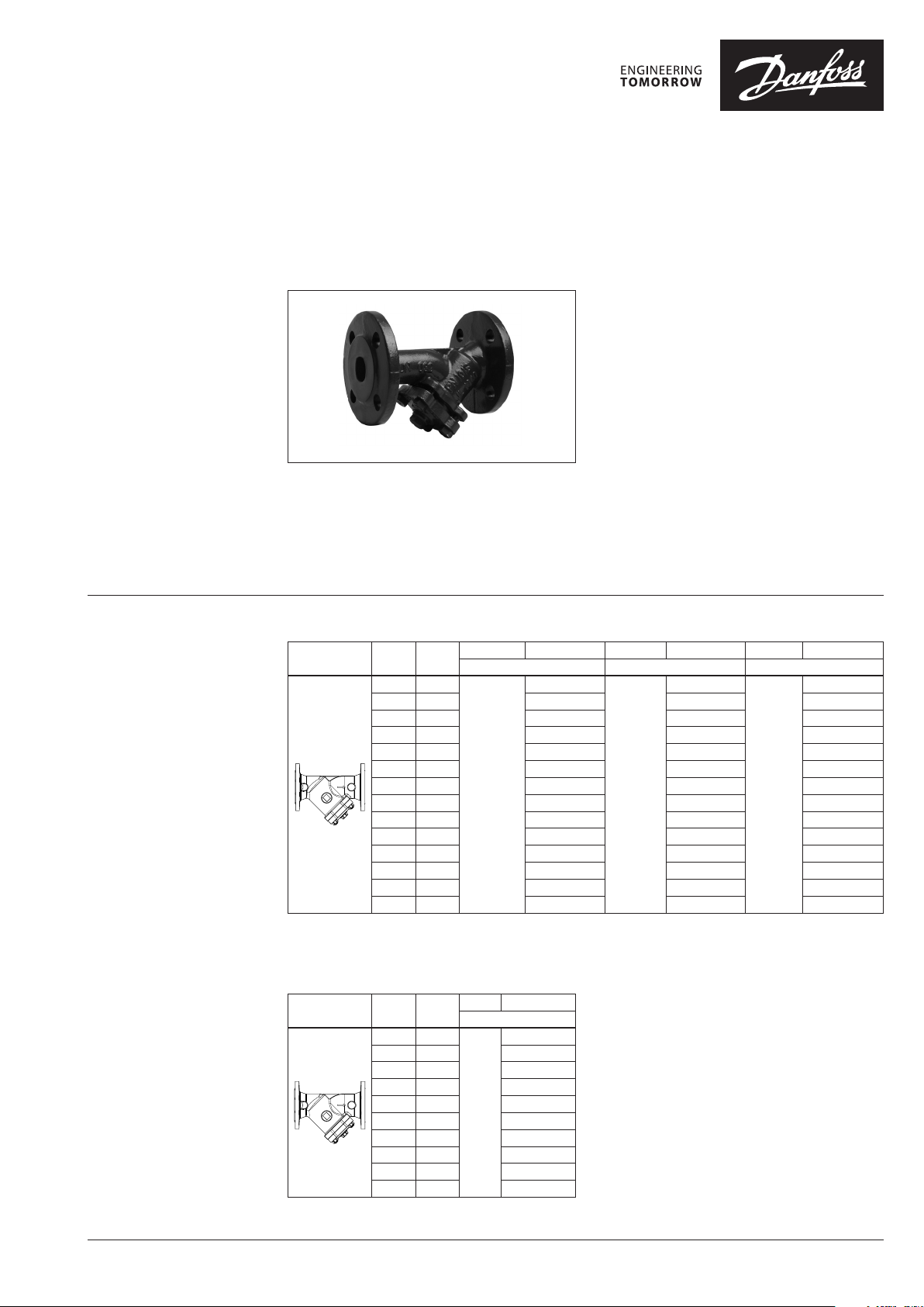
FVF strainer
Description
Ordering
Strainer is installed to protect sensitive
equipment like meters, pumps, control valves
against danger caused by foreign particles and in
wide range of other applications.
Furthermore, strainer is available with a plug,
magnetic insert or ball valve. Combination with
ball valve allowing a quick and efficient cleaning.
Main data:
• DN 15-300
• PN 16/25
FVF strainer is designed for heating, district
heating and cooling systems.
• Temperature:
- Circulation water / water with glycol:
−10 … 150 °C (PN 16), −20 … 150 °C (PN 25)
Strainer removes and retains foreign particles like
welding beads, swarf, sand, etc. carried along by
heating / cooling medium.
• Connections:
- flange (strainer) DIN EN 1092-2
- thread (ball valve)
Flange1) strainer FVF
2)
DN
k
Picture
1)
Flanges acc. to EN 1092-2 (PN 16 and PN 25 respectively)
2)
For strainers wi th normal screens
3)
To prevent scalds during drai ning the draining ball valve must b e equipped with drain hose , that leads to drainage system
(mm)
100 201 065B7734 065B 7748 065B7778
125 350 065B7735 065B7749 065B7779
150 542 065B7736 065B7750 065B7780
200 870 065B7737 0 65B7751 065B7781
250 1.26 0 0 65B7738 065B7752 0 65B7782
300 1.735 065B7739 065B7 753 065B7783
VS
(m3/h)
15 5.3
20 9.5 065B7727 06 5B7741 065B7771
25 16. 5 065B7728 065 B7742 065B7772
32 20 065B7729 065 B7743 065B7773
40 33 065B7730 065B7 744 065B7774
50 54 065B 7731 06 5B7745 065B7775
65 95 065B7732 065B774 6 065B7776
80 140 065B7733 0 65B7 747 065B7777
T
max
PN 16 with draining ball valve PN 16 PN 25
150 oC
Code No. T
065B7726
3)
max
150 oC
Code No. T
06 5B774 0
max
150 oC
Code No.
065B7770
Flange1) strainer FVF, I-pack
2)
T
Picture
1)
flanges acc . to EN 1092-2 (PN 16)
2)
for strainer s with special screens
DN
(mm)
15 5.1
20 9.2 065B7755
25 15.1 065B7756
32 18.4 065B 7757
40 30.6 065B7762
50 49 065B7763
65 86.7 065B7764
80 133.6 065B7765
100 192. 8 065B7766
125 326.4 065B7767
k
VS
(m3/h)
Code No.
max
150 oC
PN 16
065B7754
© Danfoss | 2020.08 AI160486460376en-011201 | 1
Data sheet FVF strainer
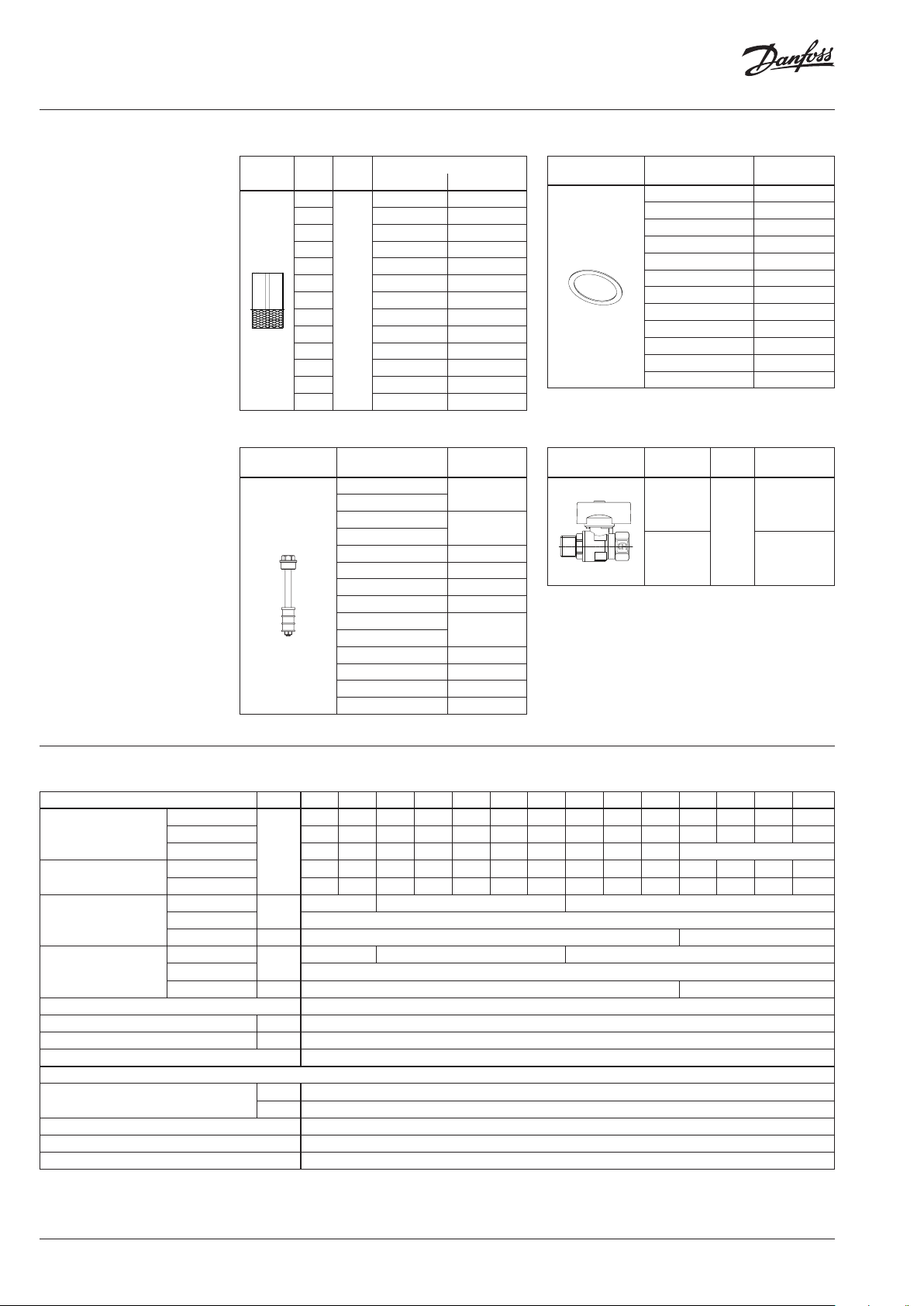
Ordering (continuous)
Spare parts FVF-Screen
Picture
DN
(mm)PN(bar)
15/20
25 0 65B7812 0 65B7826
32 065B7813 0 65B7827
40 065B7814 065B7828
50 065B7815 065B7829
65 065B7816 065B7830
16, 2 5
80 065B7817 065 B7831
100 065B7818 065B7832
125 065B7819 065B7833
150 065B7820 0 65B7834
200 065B7821 065B7835
250 065B7822 065B7836
300 065B7823 065B7837
Code No.
(normal) (fine)
065B7810 065B7824
Accessories FVF-M magnetic insert
Picture
DN
(mm)
15
20
25
32
40 065B7792
50 065B7793
65 065B7794
80 065B7795
100
125
150 065B7797
200 065B7798
250 065B7799
300 065B7800
Code No.
065B7790
065B 7791
065B7796
Spare parts FVF-Gasket
Picture
DN
(mm)
15/20 065B7886
25/32 065B7887
40 065B78 88
50 0 65B7889
65 0 65B7890
80 065B7891
100 065B7892
125 065B7893
150 065B7894
200 065B7895
250 065B7896
300 065B7897
Accessories FVF-B ball valve
Picture
DN
(mm)
10
(used for
FVF
DN 15 - 50)
15
(used for
FVF
DN 65 - 300)
T
(°C)
150
max
Code No.
Code No.
065B7802
065B7801
Technical data
Nominal diameter DN 15 20 25 32 40 50 65 80 100 125 15 0 200 250 300
normal screen
kVS value
fine screen 5.0 9.0 14. 8 18 30 48 85 131 189 320 494 818 1184 1631
special screen 5.1 9.2 15 .1 18.4 30.6 49 86.7 133.6 192 .8 326.4 -
kVS value
(with magnetic insert)
normal screen 4.8 8.6 14.9 18 29 49 86 127 183 316 489 809 117 2 1613
fine screen 4.5 8.1 13 .3 16 27 44 77 119 17 0 297 459 760 1101 1516
normal screen
Mesh size
fine screen 0.25
special screen 0.40 -
Number of meshes
normal screen
fine screen 625
n/cm
special screen 280 Flow medium Circulation water / glycolic water up to 50%
Nominal pressure PN 16 or 25
Medium temperature
Connection Flanges acc. to DIN EN 1092-2 (PN 16 and PN 25 respectively)
Materials
Body (strainer)
PN 16 Grey cast iron EN-GJL-250 (GG-25)
PN 25 Ductile iron EN- GJS-400 -18-LT (GGG 40.3)
Body (ball valve) Dezincing free brass CuZn36Pb2As
Screen Stainless steel, mat. No 1.4301
Gasket Graphite
1)
Danfoss uses env ironmentally friendl y paint that is resistant to a temperature o f 150 oC.
5.3 9.5 16.5 20 33 54 95 140 201 350 542 870 1260 17 35
m3/h
mm
o
C −10 ... 150 (PN 16), −20 ... 150 (PN 25)
0.54 0.87 1.18
150 64 25
2
1)
2 | AI160486460376en-011201 © Danfoss | 2020.08

Data sheet FVF strainer
Pressure temperature
diagram
PN
❶
25
20
❷
15
❶ EN-GJS- 400-18-LT (GGG 40.3) PN 25
➋ EN-GJL-250 (GG 25) PN 16
Note: Danfoss uses environment
friendly paint which may crack at
temperatures above 150 °C.
Flow diagram
10
0 120 140 160 180 200 220 240 260 280 300 320 340 350
Maximum allowed operating pressure as a function of medium temperature (according to EN 1092-2).
o
C
Installation positions
Standard screen Fine screen
The medium flow direction must correspond to
an arrow on the strainer body.
Strainers are to be installed in horizontal position
with mesh bonet directed downwards. Vertical
position is also allowed (be aware - when
medium flows upwards strainer retains all
foreign particles but is not able to collect them).
Sufficient space to pull out the mesh for
replacement and cleaning must be ensured.
AI160486460376en-011201 | 3© Danfoss | 2020.08

Danfos
produc
Al
Danfoss A/S
Heating Segment • heating
Data sheet FVF strainer
Design
1. Body
2. Cover
3. Screen
4. Gasket
5. Screw
6. Nut
7. Plug screw
8. Magnet
9. Washer
10. Handle
11. Ball
12. Stem
A
With magnetic insert
A
With ball v alve
Dimensions
H
L H
DN
15 130 75 95 14 65 95 14 65 2.2
20 15 0 75 105 14 75 105 14 75 3.3
25 160 90 115 14 85 115 14 85 3.8
32 18 0 90 140 19 100 140 19 100 5.0
40 200 110 150 19 110 150 19 110 6.5
50 230 120 165 19 125 165 19 125 8.5
65 290 140 185 19 145 185 19 14 5 12. 0
80 310 16 5 20 0 19 16 0 200 19 16 0 16.6
100 350 220 220 19 180 235 23 190 25.0
125 400 260 250 19 210 270 28 220 39.0
150 480 300 285 23 240 300 28 250 61. 0
200 600 360 340 23 295 360 28 310 109
250 730 470 405 28 355 425 31 370 16 2
300 850 560 460 28 410 485 31 430 280
L
DN
PN 16 PN 25
ØD Ød dk ØD d dk
mm
Ød
ØD
dk
Weight
(kg)
s can accept no responsibility for possible errors in catalogues, brochures and o ther printed material. Danfoss reserves the right to alter its products w ithout notice. This also applies to
ts already on order provided that such alterations can be m ade without subsequential changes being necessary in specications already agreed.
l trademarks in this material are p roperty of the respective companies. Danfoss and al l Danfoss logotypes are trademarks of Danfoss A/S. All rights reser ved.
Ball valve
For strainers
DN
10 15 - 50 52 43 36 10
15 65 - 30 0 69 50 52 17. 3
DN
L L1 H D
mm
.danfoss.com • +45 7488 2222 • E-Mail: heating@danfoss.com
L1
H
DN
D
L
© Danfoss | DHS-SRMT/SI | 2020.084 | AI160486460376en-011201
 Loading...