

Data Sheet
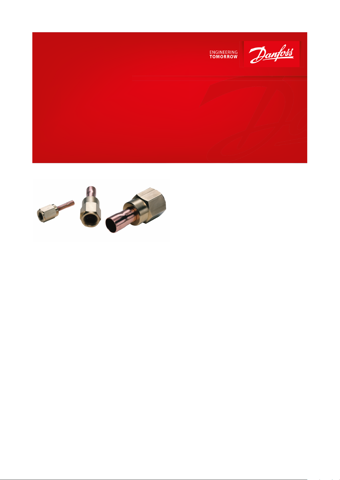
Adaptor
Type FSA
Easy and fast component replacement
With the are / solder adaptor, type FSA, are
connections can be easily and reliably changed
to solder connections.
The adaptor provides a method of joining that
preserves the advantages of are connections,
i.e. easy and fast component replacement. At
the same time, the are / solder adaptor also
provides the advantage of soldered joints, i.e. a
high degree of tightness that prevents leakage.
The adaptor contains no soft gaskets or O-rings
which age and loose their sealing properties.
Instead, it contains a copper seal which
protects the are collar against wear and
fatigue. This copper seal ensures a thightness
similar to that of soldered joints.
The copper seal must be changed each time
the adaptor is dismantled for servicing are
components.
Frost grooves in the nut mean that the
adaptors are suitable for wet environment,
where the temperature is below the water
freezing point. The nut cannot be loosened by
encapsulated ice formation.
Features
• The are / solder adaptor, type FSA, is for use
where servicing or some other factor makes a
“genuine” solder connection impractical.
• The adaptor can be used with advantage for
components with are connections on:
1.
Pressure controls
2.
Filter driers
3.
Sight glasses, etc.
AI151686417214en-000501
1
2
12Marking
Frost grooves
Size
Torque
1
⁄4 in. / 6 mm
20 Nm
3
⁄8 in. / 10 mm
30 Nm
1
⁄2 in. / 12 mm
60 Nm
5
⁄8 in. / 16 mm
100 Nm
3
⁄4 in. / 18 mm
200 Nm
Type
Designation
FSA
Flare/ solder adapter
3
Flare nut in eighth of an inch
2 =
1
⁄4 in. or 6 mm, 3 = 3⁄8 in. or 10 mm, 4 = 1⁄2 in. or 12 mm, 5 = 5⁄8 in. or 16 mm, 6 = 3⁄4 in.
6 m
Solder connection
2 =
1
⁄4 in., 3 = 3⁄8 in., 4 = 1⁄2 in., 6 = 3⁄4 in. 6m = 6 mm, 10m = 10 mm, 12m = 12 mm, 16m = 16 mm or 5⁄8 in., 18m = 18 mm
Type
Connection
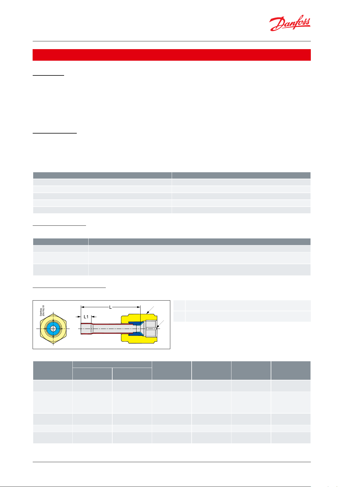
L
[mm]
L
1
[mm]
Stamping
Weight
[kg]
Flare
[in.]
Solder
[ODF]
FSA 22
FSA 26m
1
⁄4
1
⁄4
1
⁄4
in.
6 mm3939
7
7INMM
0.05
0.05
FSA 32
FSA 36m
FSA 33
FSA 310m
3
⁄8
3
⁄8
3
⁄8
3
⁄8
1
⁄4
in.
6 mm
3
⁄8 in.
10 mm
50
50
50
50
7
7
8
9
IN
MM
IN
MM
0.09
0.09
0.09
0.09
FSA 44
FSA 412m
1
⁄2
1
⁄2
1
⁄2
in.
12 mm57571010INMM
0.11
0.11
FSA 516m
5
⁄8
5
⁄8
in. or 16 mm
5712MM
0.14
FSA 66
FSA 618m
3
⁄4
3
⁄4
3
⁄4
in
18 mm68681414INMM
0.28
0.28
Adaptor, type FSA
Product specication
Standards
DIN 8964, which stipulates a maximum leak rate for refrigeration plant of < 6.4 × 10⁻⁶ mbar l/s at a dierential
pressure of 10 bar He.
The Dutch refrigeration standard (9.12.94/IBP 07d 94007, part 2.2.8.2.): In variation to regulation 2.2.8.1 anged
joints, compression joints, quick-couplings, at or conical packing or trapped O-rings will be permitted, but only if
the packing or O-ring provide the seal and are replaced if the joint is disconnected and then remade.
Technical data
Refrigerants: only approved for A1 and A2L refrigerants
Max. working pressure: PS/MWP = 46 bar
Leak rate: Max. 1 g / year
Table 1: Max. tightening torque
Type designation
Table 2: Type designation of FSA 36m
Dimensions and Weight
Figure 1: Type FSA
Table 3: Dimensions and weight of FSA
© Danfoss | Climate Solutions | 2021.03 AI151686417214en-000501 | 2

Type
Connections
Code no.
Flare
Solder
ininmm
Flare / solder adapter set: 2 pcs.
FSA 22
1
⁄4
¼-023U8002
FSA 33
3⁄83
⁄8
-
023U8004
FSA 44
1⁄21
⁄2
-
023U8006
FSA 516m
5⁄85
⁄8
-
023U8007
FSA 66
3⁄43
⁄4
-
023U8010
FSA 26m
1
⁄4
-6023U8001
FSA 310m
3
⁄8
-10023U8003
FSA 412m
1
⁄2
-12023U8005
FSA 516m
5
⁄8
-16023U8007
FSA 618m
3
⁄4
-18023U8009
Flare / solder adapter set, 1 pcs.
FSA 22
1
⁄4
¼-023U8012
FSA 32
3
⁄8
¼-023U8022
FSA 33
3⁄83
⁄8
-
023U8014
FSA 44
1⁄21
⁄2
-
023U8016
FSA 516m
5⁄85
⁄8
-
023U8017
FSA 66
3⁄43
⁄4
-
023U8020
FSA 26m
1
⁄4
-6023U8011
FSA 36m
3
⁄8
-6023U8021
FSA 310m
3
⁄8
-10023U8013
FSA 412m
1
⁄2
-12023U8015
FSA 516m
5
⁄8
-16023U8017
FSA 618m
3
⁄4
-18023U8019
Copper seal
Size
Qty.
Code no.
B2 - 4 spec.
1
⁄4
in / 6 mm
300
011L4025
B2 - 6
3
⁄8
in / 10 mm
300
011L4017
B2 - 8
1
⁄2
in / 12 mm
200
011L4018
B2 -10
5
⁄8
in / 16 mm
100
011L4019
B2 -12
3
⁄4
in / 18 mm
50
011L4020
Adaptor, type FSA
Ordering
Figure 2: Connections for
Flare/solder adapter
Table 4: Ordering of FSA
Figure 3: Copper seal
Table 5: Accessories
© Danfoss | Climate Solutions | 2021.03 AI151686417214en-000501 | 3

Document name
Document type
Document topic
Approval authority
067R1068
Manufacturers Declaration
PED
Danfoss
033F4006
Manufacturers Declaration
China RoHS
Danfoss
033F4011
Manufacturers Declaration
EU Rohs
Danfoss
Adaptor, type FSA
Certicates, declarations, and approvals
The list contains all certicates, declarations, and approvals for this product type. Individual code number may have
some or all of these approvals, and certain local approvals may not appear on the list.
Some approvals may change over time. You can check the most current status at danfoss.com or contact your local
Danfoss representative if you have any questions.
Table 6: Certicates, declarations, and approvals
© Danfoss | Climate Solutions | 2021.03 AI151686417214en-000501 | 4

Online support
Danfoss oers a wide range of support along with our products, including digital product information, software,
mobile apps, and expert guidance. See the possibilities below.
The Danfoss Product Store
The Danfoss Product Store is your one-stop shop for everything product related—no matter where
you are in the world or what area of the cooling industry you work in. Get quick access to essential
information like product specs, code numbers, technical documentation, certications, accessories,
and more.
Start browsing at store.danfoss.com.
Find technical documentation
Find the technical documentation you need to get your project up and running. Get direct access to
our ocial collection of data sheets, certicates and declarations, manuals and guides, 3D models
and drawings, case stories, brochures, and much more.
Start searching now at www.danfoss.com/en/service-and-support/documentation.
Danfoss Learning
Danfoss Learning is a free online learning platform. It features courses and materials specically
designed to help engineers, installers, service technicians, and wholesalers better understand the
products, applications, industry topics, and trends that will help you do your job better.
Create your Danfoss Learning account for free at www.danfoss.com/en/service-and-support/learning.
Get local information and support
Local Danfoss websites are the main sources for help and information about our company and
products. Find product availability, get the latest regional news, or connect with a nearby expert—all
in your own language.
Find your local Danfoss website here: www.danfoss.com/en/choose-region.
Coolselector®2 - nd the best components for you HVAC/R system
Coolselector®2 makes it easy for engineers, consultants, and designers to nd and order the best
components for refrigeration and air conditioning systems. Run calculations based on your operating
conditions and then choose the best setup for your system design.
Download Coolselector®2 for free at coolselector.danfoss.com.
Danfoss can accept no responsibility for possible errors in catalogues, brochures and other printed material. Danfoss reserves the right to alter its
products without notice. This also applies to products already on order provided that such alterations can be made without subsequential
changes being necessary in specications already agreed. All trademarks in this material are property of the respective companies. Danfoss and
the Danfoss logotype are trademarks of Danfoss A/S. All rights reserved.
© Danfoss | Climate Solutions | 2021.03 AI151686417214en-000501 | 5
 Loading...