

Page 1
Installation and Instruction
PLRCA.PI.GK0.A1.02 / 520H3006
© Danfoss Saginomiya
A. Failure to read and follow all instruction carefully before installing or
operating this flow switch could cause personal injury and/or
property damage. Save these instructions for future use.
B. NOTE FOR SAFETY
Approved by Drawing NumberCatalog NumberNamedatedrawn by
1991
APR.
PADDLE TYPE FLOW SWITCH
FQS
1/2
A-QS-90003-A
Warning
Never remove the cover when power is applied. This can result in electric shock.
Connect wiring after turning off power. This can result in electric shock.
Do not sprinkle water over the microswitch. This can result in electric shock.
Do not connect a load exceeding the electric rating. This can result in bad contacts.
Do not turn screws other than the operating value setting screw.
Incorrect operations or water leakage can occur.
Install the switch so that the arrow indication and the fluid flow match.
The switch does not work if fluid flows in the opposite direction.
In addition, paddles can be damaged.
Use fluid that does not corrode the liquid contacting material. In addition, use
fluid in liquid form. Gas or liquid mixed with gas causes unstable operations.
Connect the switch to ground. Do not connect the grounding wire to a gas pipe,
water pipe, lightning rod or the grounding wire of a telephone line.
If the grounding is not appropriate, this can result in electric shock.
Use fluid with flow velocity of 2m/s or less. In addition, avoid strong pulsating
fluid and vibration. Paddle can be damaged.
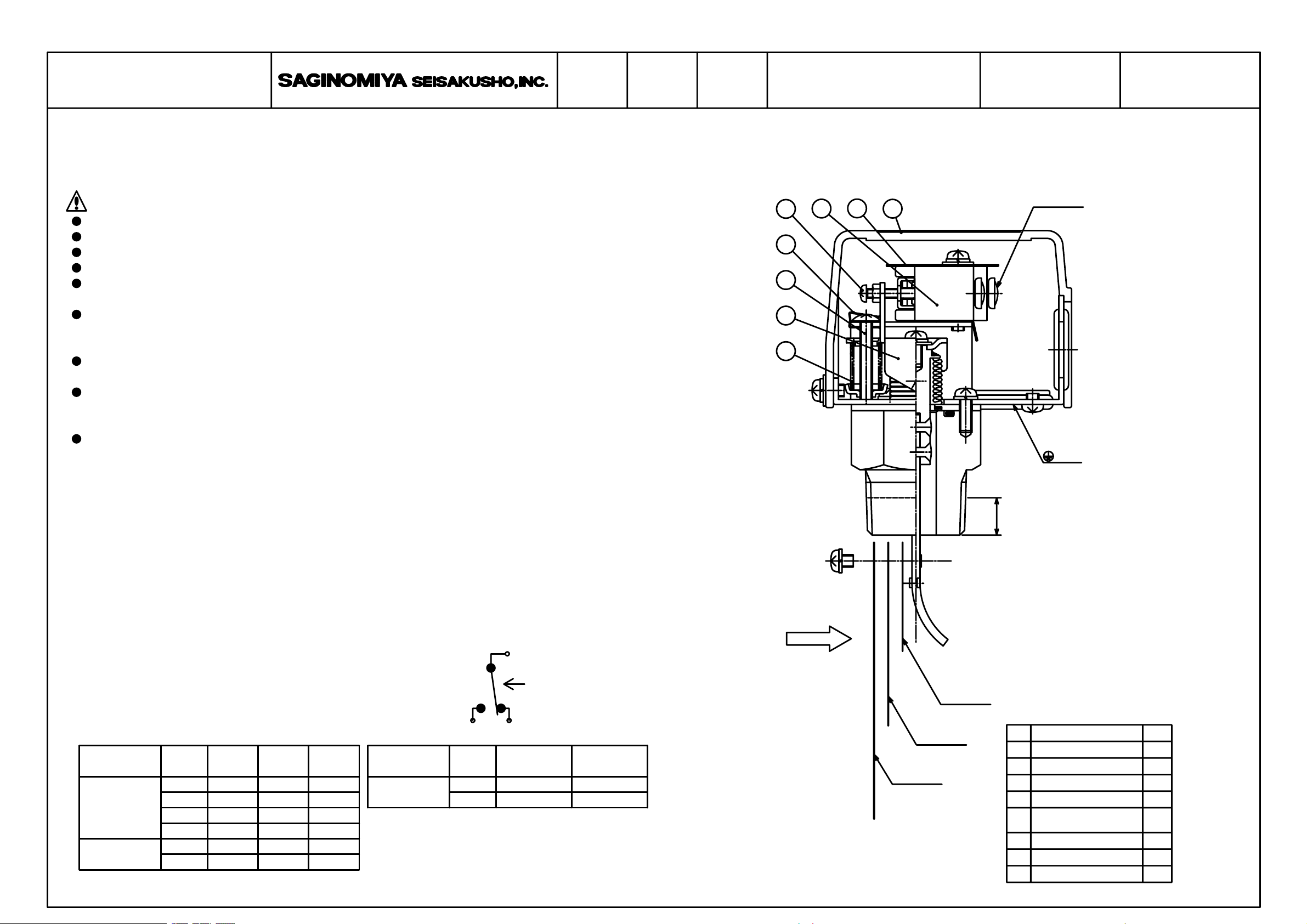
C. DESCRIPTION
Type FQS Flow Switch with SPDT micro switch detects the fluid flow in pipe line.
The electric contact block is completely sealed from the fluid in the pipe line by a bellows.
When a flow rate increases,the actuating plate⑦ will move while the resistant force ordering.
4
3
2
1
Terminal
5
6
7
8
MARK
Screwed in depth
D. SPECIFICATIONS
・Structure Open
・Liquid contacting material Copper alloy
or stainless paddle(option)
・Maximum operating pressure 0.98 MPa
・Allowable fluid temperature 5 to 80 ℃
・Endurance operations 100,000 operations
・Mounting screw R1(MPT) or NPT(option)
・Ambient temperature -25 to +80 ℃
・Ambient humidity 80 %RH or less
(No freezing, no condensation)
・Contact structure Single-pole double-throw
・Electrical ratings Unit: A
Type name,
Standard
(G)
DC high load type
(D)
Voltage
125V AC
250V AC
30V DC
125V DC
125V DC
250V DC
Resistive
15
15
6
0.5
10
3
Lamp
loadload
1.5
1.25
1.5
0.5
1.5
1.5
Motor
load
5
3
5
0.05
5
2
Type name,
Small load type
(K)
FLOW
C
Flow rate increase
A: Normally open terminal
B: Normally closed terminal
BA
C: Common terminal
symbolsymbol
Voltage
24V DC
100V AC
Minimum
applicable load
0.01
0.01
Maximum
current load
0.1
0.1
Paddle 3
Paddle 1
Paddle 2
№
Parts Name
Label
Insulated Plate
Micro Switch
Adjusting Screw
Metal Fitting For
5
Flow Adjusting Screw
Flow Adjusting Screw
Actuating Plate
Adjusting Spring
Q'ty.
11
12
13
14
1
16
17
18
Page 2
Installation and Instruction
PLRCA.PI.GK0.A1.02 / 520H3006
© Danfoss Saginomiya
Approved by Drawing NumberCatalog NumberNamedatedrawn by
1991
APR.
PADDLE TYPE FLOW SWITCH
FQS
2/2
A-QS-90003-A
D.INSTALLATION METHOD
・Provide a straight pipe section of more than 5 times the piping diameter in front and
back of the flow switch. This is used to prevent hunting due to turbulent flow.
・Basically install the switch in horizontal piping with the cover facing upward but it
can be installed in vertical piping.
However,in the case of a vertical pipe installation, the operating value may change
about 20% compared to the horizontal pipe installation.
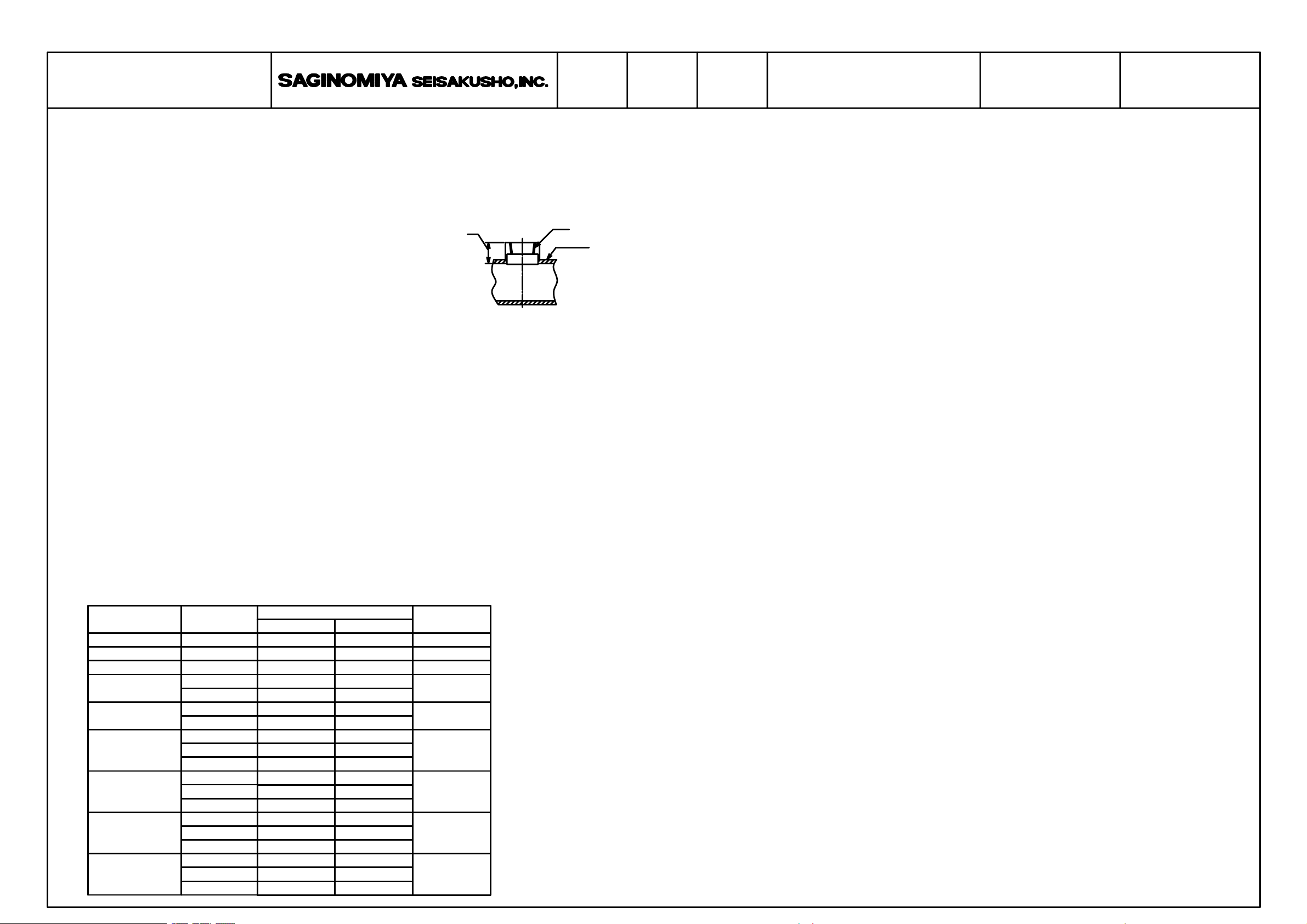
・For piping of the flow switch, use a commercially available
a
Rc1
Piping
Tee joint (conforming to JIS B 2301).
If the available Tee joint cannot be installed, adjust the
dimension “a” in the diagram on the right to that of the
Tee joint of JIS.
・When installing the flow switch to piping, the depth of the
flow switch screwed in shall be 12±1.2mm.
・For wiring,follow the instructions written on the insulation plate of the microswitch.
E.OPERATING VALUE SETTING
・When the operating value is not specified, the flow switch is shipped with the
operating value set around the minimum flow rate.
・When you turn the flow adjusting screw ⑥ clockwise, the operating point goes up.
When you turn it counterclockwise, the operating point goes down.
But if you turn the screw counterclockwise too much, the operation becomes unstable
and if you turn it further, the setting screw breaks off.
・If you have changed the setting value, make sure to operate the paddles and check
the operation of the microswitch.
・Never remove the metal fitting ⑤ because this is used to prevent the flow adjusting
screw⑥ from loosening.
・The adjusting screw ④ is exclusively used by our service personnel.
Do not use this screw for adjustment.
・When setting the operating value, refer to either decreasing flow setting value or
increasing flow setting value.
F.OPERATION ADJUSTMENT RANGE TABLE
Piping
25A (1B)
32A(1/B)
40A(1/B)
50A (2B)
65A(2/B)
80A (3B)
100A (4B)
100A (4B)
125A (5B)
150A (6B)
1
4
1
2
1
2
combination
1
1
1
1+2
1
1+2
1
1+2+3
1+2
1
1+2+3
1+2
1
1+2+3
1+2
1
1+2+3
1+2
1
Adjustment range
1266
1781
MIN
18
43
63
50
151
105
356
100
226
481
200
386
821
350
595
530
837
Unit: L/min
MAX
45
100
135
150
220
355
360
225
480
510
385
820
870
594
1265
1342
836
1780
1890
flow velocityPaddle
of 2m/s
72
120
163
264
432
612
1044
1613
2268
・This table is based on the operating point for decreasing flow.
Decreasing flow setting value means the flow switch operates when the flow rate decreases.
Increasing flow setting value means the flow switch operates when the flow rate increases.
・Differential value (difference between the decreasing flow operating value and the
increasing flow operating value) is not determined specifically. The guideline value
is as follows:
Less than 50L/min: About 10L/min
From 50L/min to less than 100L/min: About 15L/min
100L/min or more: About 20% of the setting value
・This table is based on the condition when the depth screwed in is kept within 12±1.2mm.
Tee joint of JIS.
・Paddle size is in the following order: 1<2<3
flow switch screwed in shall be 12±1.2mm.
・When the setting value is not specified, the attached paddle 1 can be used for 40A
or less, 1+2 for 65A or less and 1+2+3 for 80A or more.
・When more than two paddles is attached, you can change the flow rate adjustment range
by removing the paddles one by one in order of the longer paddle first.
・To install the paddles, install the paddle 1 first then stack the paddle 2 and then
the paddle 3.
G.OPERATION CHECK
Install and calibrate the Product correctly and then check its operation to confirm
correct function of the whole system when using.
H.LIMIT ON APPLICATION
The product is not designed nor manufactured for an use in such equipment or system
that is intended to be used under such circumstances that may affect human life.
For application requiring extreme high reliability, please contact the Company first.
I.SCOPE OF WARRANTY
Unless otherwise agreed by the parties, warranty period of the Product shall be one
year after date of delivery to Buyer.
In case of failure attributable to the Company within such period, the Product shall
be repaired or replaced without charge, provided that any one of followings are out
of the warranty :
① Improper handling or application by user.
② Modification or repair by other than the Company.
③AnyfailuretobecausedbyactsofGod,fire,stormorthelike,war,riot
or the like and other causes beyond the control of the Company.
Warranty described in this paragraph means the warranty for the Product itself and
does not include warranty for any consequential damage arising out of or occasioned
by a defect or failure of the Product.
A FEB.12.2004 REVISION K.Suzuki
 Loading...