

Datasheet
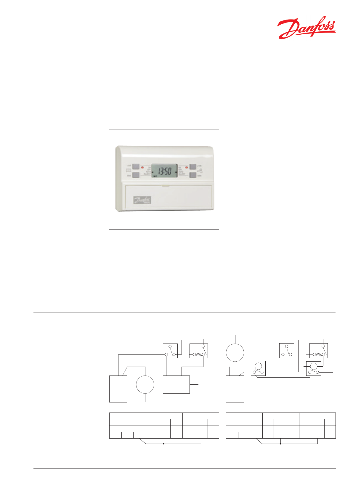
FP975
Electronic 7-Day Programmer
Application
The FP975 7-day full programmer off ers all
the control fl exibility and user features of its
counterpart, FP715, in the regular Mk18 range,
but with two important diff erences:
1) This unit is intended specifi cally to replace, or
upgrade systems with, Danfoss Randall Mk.9
time controls. They have British Gas Standard
wallplates which are used by many other
models, including the Danfoss Randall SET
range, the Horstmann 425 Diadem and Tiara,
and their 525 and 527 models.
2) This model has voltage-free output contacts,
making it applicable to systems with low
voltage control circuits, e.g. combination
boilers or warm air.
The unit is supplied with a SET wallplate but,
simply by re-positioning a small switch on the
back, interchangeability is achieved with Mk.9
controls.
Replace models With
922 & 972 FP975
The FP975 is supplied as a full 7-day control, but
the installer can easily and quickly convert it to a
weekday/weekend or 24 hour unit if preferred.
• British Gas Standard wallplate provides
interchangeability with other popular time
controls
• Total control fl exibility
• Easy Programming
• Stylish, compact design
• Easy change to Weekday/Weekend control
• Easy GMT/BST time change
• Day programme copy facility
• AM/PM or 24 hour clock display
• Up to 3 Ons/Off s each day
• Built-in, ready-to-use programmes
• Battery back-up
Systems
The FP975 will plug on to the wallplates of
both Danfoss Randall Mk.9 and SET time
controls.
When used on an existing correctly wired
MK.9 wallplate, no wiring changes need to
be made but the small switch on the back
of the new unit should be re-positioned as
shown overleaf.
For SET replacement, no such adjustment
is necessary.
FP975 Heatshare System (mid-position valve) FP975 Heatplan System (2x2 port valves)
Cylinder
‘stat
DHWONDHW
Links
COM
N
N
Room
‘stat
Spring return
DHWONDHW
OFF
Cylinder
‘stat
N
Boiler Pump
N
Mains DHW HTG
922 or 972 OFF COM ON OFF COM ON
SET5 ON COM OFF ON COM OFF
E N L 1 2 3 4 5 6
Part No. 208 Issue 07 10/09
3 Port
Mid Position
Valve
Earth not shown.
Ensure earth continuity
throughout.
Links
HTG
ON
N
N
Room
‘stat
N
Pump
N
N
Boiler
Mains DHW HTG
922 or 972 OFF COM ON OFF COM ON
SET5 ON COM OFF ON COM OFF
E N L 1 2 3 4 5 6
Spring return
valve in DHW
HTG
ON
valve in HTG
HTG
COM
1
Datasheet
FP975 Electronic 7-day Programmer
Specifi cations
Wallplate and Conversion
The FP975 programmer is supplied exfactory as a 7-day unit.
Simply by re-positioning small switches
as shown, it can become a weekday/
weekend or 24 hour control. The same
switch determines whether or not the
FP975 is HW/CH linked for use with basic
gravity heating systems.
Features FP975 Full Programmer
7-day, 5-day/2-day or 24 hour •
Water/Heating linkable for basic systems •
Output Channels Independent HW and CH
On
Programmes Selectable
Weekdays Saturday & Sunday
6:30am
ON
8:30am
5:00pm
OFF
ON
OFF
ON
OFF
Factory pre-set ON/Off times
All changeable
Ons and Off s per day Up to 3
Advance Override Per channel
+1 Hour Override Per channel
Voltage Rating 220/240 Vac, 50 Hz
Contact Rating 3 (1) A
Switching Action 2 x SPDT Voltage Free
Maximum Ambient Temperature 45°C
Memory back-up Lithium - minimum of 24 hours
Dimensions 150 wide x 99 high x 42 deep
Outline of unit
Allow screwdriver access above unit
12:00pm
12:00pm
10:30pm
Wall or plaster
box tting
O ff
Auto
Allday
(per channel)
7:00am
10:00am
12:00pm
12:00pm
5:00pm
10:30pm
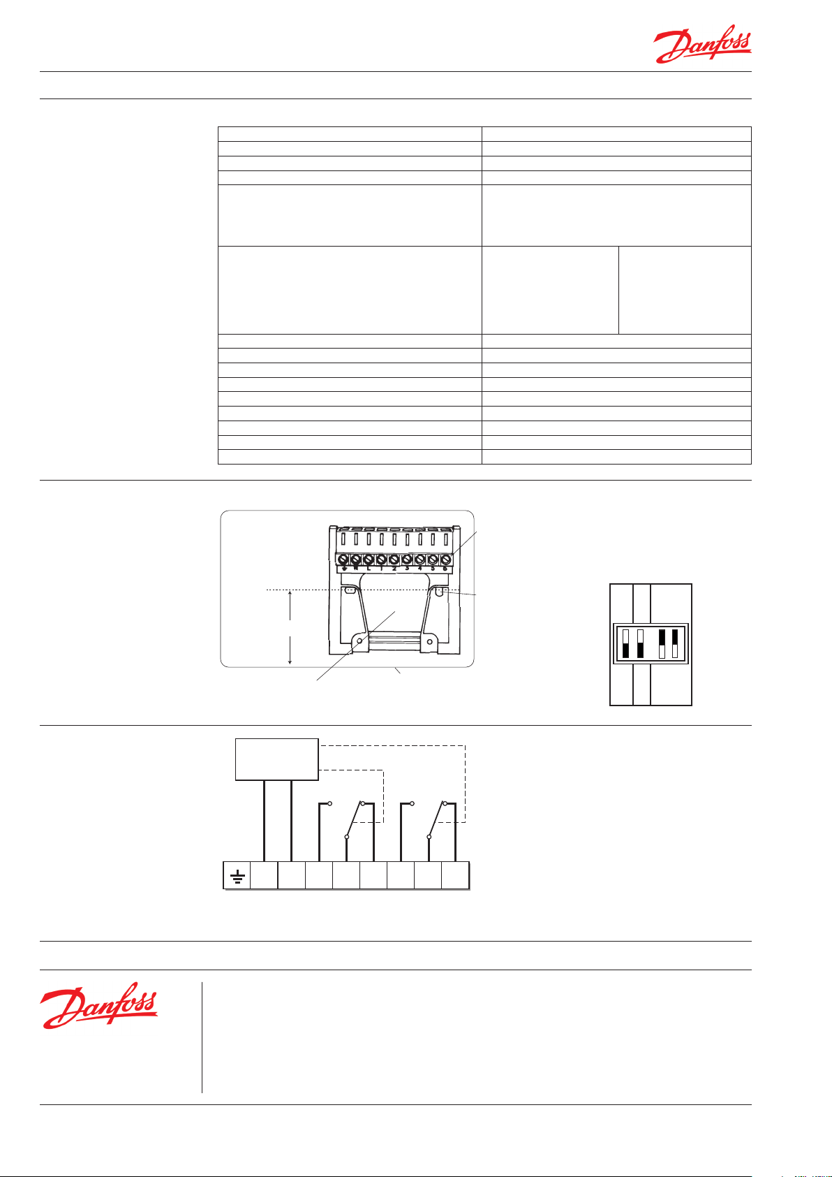
Setting Operating Mode
Four small switches on the rear of the case
are used to set the operating mode.
TOP
7 DAY/24 HR
PUMPED
Terminal block
43mm
MK.9
LEFT
5/2 DAY
SET
GRAVITY
Rear entry cable access
Allow 20mm clearance below unit
Surface xed cable
bottom entry knockouts
ON
OFF
ON
OFF
ON
OFF
24 HR
RIGHT
7 DAY
Wiring
Electronics
C
HTG
N/C
OFF
Please note:
Operating mode switch at factory setting,
ie. for new installation or for direct replacement of SET range.
N/C N/O
3
OFF
C
4 5 6
ON
N
Mains
N/O
L21
ON
DHW
Danfoss can accept no responsibility for possible errors in catalogues, brochures, and other printed material. Danfoss reserves the right to alter its products without notice. This also applies to products already
on order provided that such alterations can be made without subsequent changes being necessary in specifications already agreed.
All trademarks in this material are propert y of the respective companies. Danfoss and the Danfoss logotype are trademarks of Danfoss A/S. All rights reserved.
Danfoss Ltd.
Ampthill Road
Bedford MK42 9ER
Tel: 01234 364621
Fax: 01234 219705
Email: ukheating@danfoss.com
Website: www.heating.danfoss.co.uk
2
Part No. 208 Issue 07 10/09 VDAFB212
 Loading...