

Page 1
MAKING MODERN LIVING POSSIBLE
Danfoss Heating
FP975
7-Day Electronic Programmer
Installation Guide
Page 2

For a large print version of these instructions
please call Marketing on 0845 121 7400.
®
Certification Mark
Danfoss can accept no responsibility for possible errors in catalogues, brochures, and other
printed material. All trademarks in this material are property of the respective companies.
Danfoss and the Danfoss logotype are trademarks of Danfoss A/S. All rights reserved.
2
FP975
Page 3

Installation Instructions
FP975
7 Day Electronic Programmer
GB
Index
1.0 Installation Guide .....................................................................................4
2.0 System Overview .......................................................................................4
3.0 Installation ...................................................................................................4
3.1 DIL Switch Settings ...........................................................................4
3.2 New Installations................................................................................5
3.3 Existing Installations .........................................................................8
3.4 Wiring .....................................................................................................9
3.5 230 Vac Fully Pumped System - Zone Valves ...........................9
3.6 230 Vac Controlled Gravity Hot Water .....................................10
3.7 230 Vac Fully Pumped System - Mid-Position Valves ......... 10
3.8 Wiring Conversions ........................................................................ 11
Danfoss Heating
3
Page 4
GB
1.0 Installation Guide
Please Note:
This product should only be installed by a qualifi ed electrician or
competent heating installer and should be in accordance with the
current edition of the IEEE wiring regulations.
2.0 System Overview
Specifi cation
Power supply 230 Vac ± 15%, 50/60 Hz
Switching action
2 x SPDT voltage free, Type 1B
Switch rating 10-230 Vac, 3(1)A
Battery back-up 24 hours minimum
Timing Accuracy ±1 min/month
Setting/Running Accuracy ±1 minute
Max. Ambient Temperature 45°C
Dimensions, mm (W, H, D) 148 x 96 x 42
Design standard EN 60730-2-7
Control Pollution Situation Degree 2
Rated Impulse Voltage 2.5kV
Ball Pressure Test 75°C
3.0 Installation
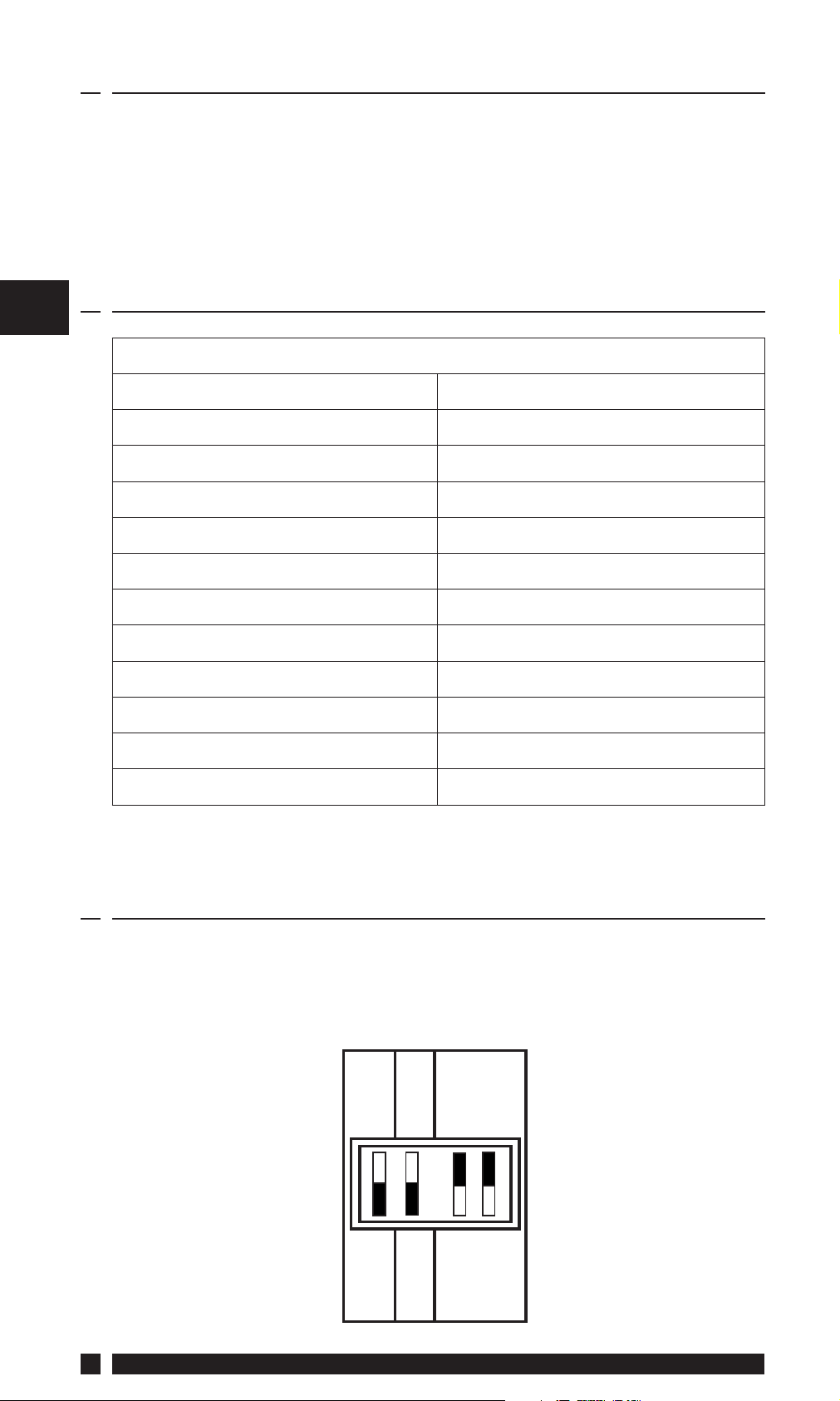
3.1 DIL Switch Settings
S
Before mounting the unit, ensure the 4 DIL switches on the rear of
the unit have been moved to the required settings.
TOP
24 HR
7 DAY/24 HR
PUMPED
MK.9
LEFT
5/2 DAY
SET
GRAVITY
4
7 DAY
RIGHT
FP975
Page 5

MK.9 or SET
The FP975 is supplied fi tted with a Danfoss Randall SET wallplate.
However the FP975 will also mount directly onto a Danfoss Randall
MK.9 wallplate without the need for wiring changes. However when
used with existing MK.9 wallplates the left hand switch must be set
in the MK.9 position to re-confi gure the time control to match MK.9
wiring connections.
PUMPED or GRAVITY
When this switch is in the PUMPED position the Heating and Water
outputs are UNLINKED. When in the GRAVITY position the Water
output is LINKED to the Heating output so that whenever the
Heating is ON the Water will also be ON regardless of the Water
programme.
Place the switch in the PUMPED position if the system being
controlled is a) fully pumped with a mid-position valve, b) fully
pumped with a two port zone valve in each circuit, c) GRAVITY
Hot Water, PUMPED Heating with a two port zone valve with SPDT
auxiliary switch in the gravity primary circuit (and wired in accordance
with diagrams on pages 9-10).
GB
Place the switch in the GRAVITY position if the system being
controlled is a) fully pumped, but with only a single two port zone
valve in the Heating circuit, b) GRAVITY Hot Water, PUMPED Heating
with no zone valves.
7 Day, 5/2 Day or 24 Hour
When both switches are in the 7 DAY position each day of the
week may be programmed with diff erent ON/OFF times. When the
switch is in the 5 DAY/2 DAY position, weekdays (Mon-Fri) can be
programmed with one set of ON/OFF times, and weekends (Sat-Sun)
can be programmed with a diff erent set. When both switches are in
the 24 hour position the same set of times will be repeated in every
24 hour period.
3.2 New Installation
1. Fix the wallplate to the wall or plaster box as required.
When fi xing the wallplate note that the terminals are at the top,
and the vertical centre line of the unit lies between terminals N
and L.
2. Surface cables can only enter from below the unit. If mounted on
a plaster box, cables can enter from the rear through the aperture
in the wallplate.
Danfoss Heating
5
Page 6

GB
3. The FP975 off ers direct plug-in replacement to the following
models (see below):
Position
Mode Sw
Type
Wallplate
Gravity H.W.
Gravity Selector
Systems Pumped/
Fully Pumped
Gravity Selector
Systems Pumped/
Position
Position
FP975 Pumped Gravity SET SET
922 Unlinked Linked MK.9 MK.9
972 Unlinked Linked MK.9 MK.9
SET 5 Unlinked Linked SET SET
SET 2* Unlinked Linked SET SET
Tiara 425 Pumped Gravity SET SET
Tiara 525 Pumped Gravity SET SET
Diadem 425 Pumped Gravity SET SET
Tiara 527 Pumped Gravity SET SET
6
Direct Plug-In Upgrade for Existing Programmers
Manufacturer Model
Danfoss Randall
Horstmann
FP975
Page 7

IMPORTANT NOTE
If the timeswitch to be replaced is listed below it may be worth
considering a FP715 Si as an alternative to the FP975. The FP715 Si
off ers wallplate compatibility for those models listed below, although
some re-wiring may be required.
MAKE MODELS
ACL LS2411, LS522, LS722, LP241, LP522, LP722
Drayton Tempus 3, Tempus 4, Tempus 7
Landis & Gyr RWB 2, RWB 2-9, RWB 200, RWB 252, RWB 20, RWB 40
Glowworm Mastermind
Potterton Mini-Minder
If the new unit is replacing an existing time control having an
incompatible wiring confi guration, then the wiring conversions
(tables A and B, pages 12-15) will be of assistance.
GB
4. For wiring connections please refer to diagrams on pages 9-10.
Please note, the FP975 does not require an earth connection,
although a terminal is provided for earth continuity purposes.
5. Ensure that the two retaining screws on the top of the timeswitch
are fully unscrewed. Locate the retaining lugs on the bottom
inside surface of the plug-in module under the wallplate base and
hinge the unit upwards until the module is pressed fully against
the top of the wallplate. Tighten the two screws on the top of the
module to secure the module to the wallplate.
6. A small blanking plug is supplied to blank the unused recessed
bottom fi xing screw.
7. Before setting the programmes the unit should be RESET by
pressing the recessed button marked R/S. Ensure the mains
power to the control circuit is switched on, and check the circuits
as follows.
8. Use the
switch the hot water output ON. Adjust the cylinder thermostat
and check the service operates correctly. Use the SELECT button
to get to OFF mode and check that the service does not operate.
9. Use the
switch the heating output ON. Adjust any remote thermostat(s)
and check that the service operates correctly. Use the SELECT
button to get to OFF mode and check that the service does not
operate.
Danfoss Heating
(Hot Water) SELECT button to get to the ON mode to
(Heating) SELECT button to get to the ON mode to
7
Page 8

GB
3.3 Existing Installation
Ensure that the power to the existing unit is switched off prior to
removal.
SYSTEMS RE-USING EXISTING WALLPLATE
Use the table on page 6 to confi rm wallplate compatibility.
• If the existing wallplate is of the SET pattern, follow instruction
5-9 from the “New Installations” section.
• Should the existing product be a Danfoss Randall MK.9 time
control the instructions below should be followed:
1. Remove and discard the white test point cover fi tted to the top
of the MK.9 wallplate.
2. Slide the small switches on the rear of the module marked MK.9 SET to the MK.9 position.
3. Ensure that the two retaining screws on the top of the timeswitch
are fully unscrewed. Firmly press the module onto the wallplate
and tighten the two screws on the top of the module. An additional
fi xing screw to hold the bottom of the unit onto the wallplate is
packed separately and must be fi tted. The screw should be placed
into the recessed hole, beneath the programming fl ap, adjacent
to the COPY button, screwed through the plastic retaining ring
and securely tightened.
4. Follow steps 5-9 from the “New Installations” section.
SYSTEMS HAVING INCOMPATIBLE BACKPLATES
Follow the “New Installations” instructions paying particular attention
to item 3).
8
FP975
Page 9

3.4 Wiring
N/O
ON
N
L123
45
6
TIMER
OFF
COM
DHW
ON
N/C
COM
HTG
OFF
N/O
N/C
For 230 Vac systems link L, 2 & 5.
GB
For Wiring Conversion tables see pages 12-15.
Always switch off mains fi rst and never fi t programmer to a live
wallplate.
3.5 230 Vac Fully Pumped System
2 x 2-port Zone Valves with Aux. Sw. PUMPED switch selection
MAINS
fused 3A
N L 1 2 3 4 5 6
N
230
Vac
L
DHW
ON
DHW
COM
ATC
DHW
OFF
HTG
ON
HTG
COM
RMT
HTG
OFF
Earths not
shown.
Ensure
continuity
throughout
HEAT
PLAN
Danfoss Heating
DHW
VALV E
BOILER
HTG
VALV E
PUMP
9
Page 10

3.6 230 Vac Controlled Gravity Hot Water
Pumped Heating System PUMPED Switch Selection
GB
230
Vac
N
L
MAINS
fused 3A
DHW
ON
DHW
COM
DHW
OFF
HTG
ON
HTG
COM
N L 1 2 3 4 5 6
ATC
RMT
HP28C
BOILER
PUMP
Earths not
shown.
Ensure
continuity
throughout
HTG
OFF
3.7 230 Vac Fully Pumped System
3-Port Mid-Position Valve PUMPED Switch Selection
MAINS
fused 3A
DHW
ON
DHW
COM
DHW
OFF
HTG
ON
HTG
COM
N L 1 2 3 4 5 6
230
Vac
N
L
HEAT
BOILER
ATC
HS3
PUMP
SHARE
HTG
OFF
RMT
Earths not
shown.
Ensure
continuity
throughout
10
FP975
Page 11

3.8 Wiring Conversions
See pages 12-15
WIRING CONVERSIONS to be used when replacing the following
programmers with the FP975. Some time controls are connected
diff erently depending on the type of system they are controlling.
Consult the column headed “NOTE This conversion ...” to determine
whether Table A (pages 12-13) or Table B (pages 14-15) should be used.
If in any doubt, contact our Technical Services Department before
proceeding with the replacement.
GB
Danfoss Heating
11
Page 12

GB
where these
block may be required
An additional terminal
terminated
disconnected leads
(or pairs) should be
ABCD
NOTE
This conversion applies
only if....
are LINKED
Terminals 5,8 & 10
Programme
selectors UNLINKED
12
N L ON COM OFF ON COM OFF
MAINS WATER HEATING
Table A
DANFOSS RANDALL
FP975 (SET MODE)
Fully Pumped Systems - ensure
Pumped/Gravity switch is in
NL123456 LINK L - 2 - 5 ABCD
‘Pumped’ position
DANFOSS RANDALL 4033 7 6 4 1 5 2 - 3
HORSTMANN 423,
2,3 1 5 - 4 7 - 6 8
AMETHYST 7 & 10
HORSTMANN 424 GEM 2,3 1,10 4 5 6 7 8 9
HORSTMANN LEUCITE 423 & 424 2 1 3 5 4 6 7 8 Terminals 5 & 7 are LINKED
HONEYWELL ST669 N L 6 8 7 3 5 4
POTTERTON EP2000, EP3000 N L 3 - 1 4 5 2
RANDALL 3033 1,7 6 4 - 5 2 - 3
RANDALL 702 N L 3 6 4 1 5 2
SANGAMO FORM 1 410 & 414 4,5 6 1 3 2 8 - 7
SANGAMO S409/1 N,1,3 L 2 - - 5 - - 6,4
SANGAMO S409/3 3,6 7 5 - 4 1 - 2
FP975
Page 13

where these discon-
should be terminated
nected leads (or pairs)
block may be required
An additional terminal
ABC
A/S3
GB
NOTE
This conversion applies
only if....
Programme
selectors UNLINKED
Programme
selectors UNLINKED
Used in a system having
water and heating
independent control of
MAINS WATER HEATING
Table A continued
DANFOSS RANDALL
FP975 (SET MODE)
Danfoss Heating
N L ON COM OFF ON COM OFF
NL123456 LINK L - 2 - 5 ABCD
SATCHWELL LIBRA & DHP 2201 1 2 6 7 8 3 4 5
N,2,4 L 1 - - 3 - -
SATCHWELL ET 1401 & 1451 1 2 7 6 8 4 3 5
SMITHS IND. CENTROLLER 90 1 2 5 - - 4 - - 3 6
SMITHS IND. CENTROLLER 1000 N L 3 - 1 4 - 2
SWITCHMASTER 800 & 805 N L 3 - 4 1 - 2
SWITCHMASTER 900 & 9000 N L 3 - 4 1 - 2
VENNER CHC/W2 (WITH STAT) N,2,4 L 1 - - A/S - -
VENNER CHC/W2
N,3 L 2 - 1 A/S - 4 A/S5
(AIR STAT LINKED)
VENNER VENOTROL 80M & 80PM
N,3 L 2 - 1 5 - 4
(WITH AIR STAT)
VENNER VENOTROL 80M & 80PM
(AIR STAT LINKED)
13
Page 14

GB
where these discon-
should be terminated
nected leads (or pairs)
block may be required
An additional terminal
ABCD
NOTE
This conversion
applies only if....
LINK L - 2 - 5 ABCD
123456
- - 4,7 5 6
(8)
AIR
STAT
--
(8)
BOILER
Programme
selectors LINKED
14
N L ON COM OFF ON COM OFF
MAINS WATER HEATING
Table B
DANFOSS RANDALL
FP975 (SET MODE)
Gravity DHW, Pumped Heating Systems -
ensure Pumped/Gravity switch is in ‘Gravity’
5 3,6 1 - - 2 - -
NL
position
DANFOSS RANDALL
N L,1,3 2 - - 4 - - 5 6
102/102E/102E5/102E7
HORSTMANN 423 DIAMOND
POTTERTON 423
HORSTMANN 424 DIAMOND N L,1,3 2 - - 4 - - 5
HORSTMANN CORAL 423 & 424 2,3 1
POTTERTON EP2000, EP3000 N L 3 - 1 4 5 2
DANFOSS RANDALL 3060 & 3020P 1,7 6 4 - - 2 - - 3 5
RANDALL 701 N L 3 6 4 1 5 2
SANGAMO M5 410 FORM 4 4,5 3 1,6 - 2 8 - 7
SANGAMO S409 FORMS 1 & 4 N,1,3 L 2 - - 5 - - 6,4
SANGAMO (EARLY MODEL) S410 FORM 4 N,2 L 1,3 - - 4 - - 1 & 3 are LINKED
SATCHWELL LIBRA 1 2 6 7 8 3 4 5
FP975
Page 15

ABC
A/S, 3
GB
Programme
selectors LINKED
Programme
selectors LINKED
Used in a system
having control
of water only or
water and
heating together
SMITHS IND. CENTROLLER 100 N L 3 - - 2 - - 1 4
SMITHS IND. CENTROLLER 60 1 2 5 - - 4 - - 3
SMITHS IND. CENTROLLER 10 N L 3 - - 2 - - 1,4
Danfoss Heating
SMITHS IND. CENTROLLER 70 1 2 5 - - 4 - - 3 6
SMITHS IND. CENTROLLER 1000 N L 3 - 1 4 - 2
SWITCHMASTER 320 & 350 N 4,L 3 - - 1 - - 2
SWITCHMASTER 400 N L 3 - - 1 - 4 2
SWITCHMASTER 600 N L 3 - - 1 - - 2 4
SWITCHMASTER 900 & 9000 N L 3 - 4 1 - 2
VENNER VENOTROL N,A,M L, L1 V - - S,F - - T,P O
VENNER VENOTROL 80 (AIR STAT) N,1,3,4 L 2 - - A/S - - A/S, 5
VENNER VENOTROL 80 (AIR STAT LINKED) N,1,3,4 L 2 - - 5 - -
VENNER CHC/W2 (WITH STAT) N,2,4 L 1 - - A/S - -
VENNER CHC/W2 (AIR STAT LINKED) N,2,4 L 1 - - 3 - -
VENNER VENOTROL 80P (WITH AIR STAT) N,1,3 L 2 - - A/S - 4 A/S, 5
VENNER VENOTROL 80P (AIR STAT LINKED) N,1,3 L 2 - - 5 - 4
15
Page 16

Danfoss Ltd.
Ampthill Road
Bedford MK42 9ER
Tel: 01234 364621
Fax: 01234 219705
Email: ukheating@danfoss.com
Website: www.heating.danfoss.co.uk
Part No. 8585v01s7-03 03/11
 Loading...