

MAKING MODERN LIVING POSSIBLE
FP735Si
Electronic 3-Channel Full Programmer for
Heating and Hot Water with Service Interval Timer
Danfoss Heating
Installation Guide

GB
For a large print version of these instructions
please call Marketing on 0845 121 7400.
This product complies with the following EC Directives:
®
Certification Mark
Danfoss can accept no responsibility for possible errors in catalogues, brochures, and other
printed material. All trademarks in this material are property of the respective companies.
Danfoss and the Danfoss logotype are trademarks of Danfoss A/S. All rights reserved.
2
Electro-Magnetic Compatibility Directive.
(EMC) (2004/108/EC)
Low voltage Directive.
(LVD) (2006/95/EC)
FP735SI
Installation Instructions
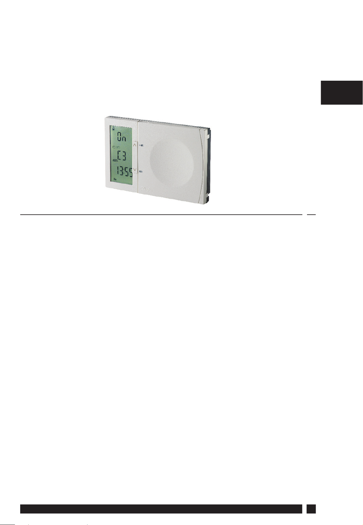
FP735Si
Electronic 3-Channel Full Programmer for
Heating and Hot Water with Service Interval Timer
Index
GBGB
1.0 Installation Guide ................................................................................4
2.0 System Overview .................................................................................4
3.0 Installation ..............................................................................................5
3.1 Removing the wallplate .............................................................5
3.2 Installation considerations ........................................................5
3.3 Wiring ...............................................................................................5
3.3 Mounting the unit ........................................................................6
3.4 Unit startup .....................................................................................6
4.0 Programming Options ......................................................................6
4.1 Normal programming .................................................................6
4.2 Advanced programming ...........................................................7
5.0 Pre-programmed Parameters ........................................................8
5.1 Advanced programming ...........................................................8
5.2 Normal programming .................................................................8
6.0 Display Information......................................................................... 10
7.0 Advanced Programming ............................................................... 11
8.0 Service Interval Timer .....................................................................14
9.0 Copy Functions .................................................................................. 14
10.0 The Information Key ........................................................................ 16
11.0 How to Reset The Unit .................................................................... 16
11.1 Reset ............................................................................................... 16
11.2 Full reset ........................................................................................ 17
12.0 System Wiring Example ................................................................. 18
Danfoss Heating
3

1.0 Installation Guide
Please Note:
This product should only be installed by a quali ed electrician or
competent heating installer and should be in accordance with the
GBGB
current edition of the IEEE wiring regulations.
2.0 System Overview
Timer Features FP735Si
Power supply 230V, 50Hz
Memory backup Retained for the life of the product
Factory set calendar clock Automatic summer/winter time change
Switching action of output relay 2 x SPDT, 1 x SPST, Type 1B
Switch rating of relay contact 3 x 3(1) A, 230 VAC
Rated Impulse Voltage 2.5 kV
Dimensions (mm) 140 wide x 91 high x 29 deep
Ball Pressure Test 75°C
Design Standard EN 60730-2-7
Control Pollution Situation Degree 2
Time accuracy ± 1 minute per month
IP rating IP30
Software Classi cation A
4
FP735SI
3.0 Installation
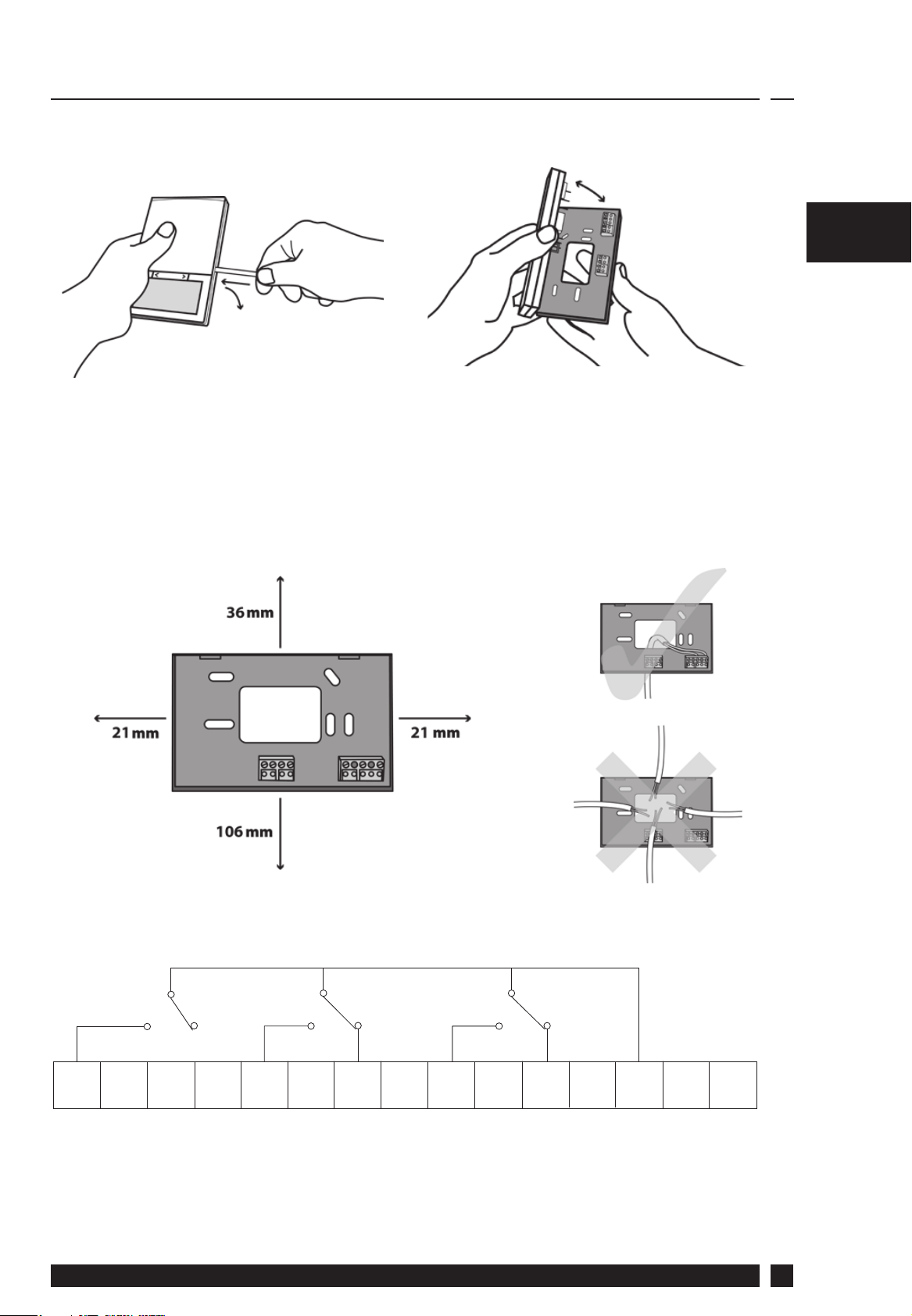
3.1 First remove the wallplate from the back of the unit.
3.2 From the top left hand corner of the wallplate, there must be
clearances of at least 21mm to the right, 21mm to the left, 36mm
GBGB
above and 106mm below in order to mount the plug-in module.
3.3 Wiring
3 on
Note: A typical system wiring example is shown on page 18
Danfoss Heating
2 on
2 off
1 on 1 off
L
N
5

3.4 Mount the unit on the wallplate
Note: Always switch
the mains o rst
GB
GB
and never t/remove
the timer to/from a
live wallplate.
3.5 With the unit powered up, it is recommended to press and
release the RESET button to start up the FP735Si unit.
4.0 Programming Options
FP735Si is delivered with a set of parameters that have been preprogrammed to cover the most typical type of installations. See
(5.0). If a di erent parameter setup is wanted the unit provides two
programming options:
4.1 Normal programming
Normal Programming is meant for setting the timing pro le that
controls the ON and OFF periods for the room heating and for the hot
water. A daily pro le may be programmed and a pro le can control
the entire week where the weekend may be handled separately. Also a
timing pro le for a holiday can be entered.
As part of the normal daily operations, a simple one-button press
(+HRS) can extend a running ON period for room heating and/or hot
water by one hour. This can be repeated 3 times giving up to 3 hours
extension.
6
FP735SI

By pressing ADV (advance), the user can jump to the next event in the
daily timing pro le. If for instance, the user wants to bring on the room
heating immediately whereas the pro le has been programmed to
bring it on in two hours, the user can simply press ADV and the heat
will be turned on.
See the User Guide for normal programming instructions.
4.2 Advanced Programming
Advanced Programming is meant for changing certain parameters
that are usually only set once. Advanced Programming can typically
be made by the installer as part of the system installation and setup.
GB
GB
Danfoss Heating
7

GB
GB
5.0 Pre-programmed Parameters
FP735Si is delivered with a set of pre-programmed parameters.
5.1 Advanced Programming
The following pre-programmed parameters can be changed in the
Advanced Programming:
Function/parameter Pre-programming
A+B days (disabled, enabled) Disabled
Copy functions
(standard or advanced copy function)
Summer/winter shift
(automatic or manual)
Backlight (always o , always on,
15s after last key press)
4 events or 6 events per day 6 events
Operating mode
(7 days, 24 hours, 5 + 2 week days)
Keyboard lock (locked, not locked) Not locked
Service interval (disabled, enabled) Disabled
Note: for the UK market, the FP735Si comes with a default 12 hours clock (AM/
PM) setup.
Standard
Automatic
15s after last key press
7 days
5.2 Normal Programming
The following pre-programmed parameters can be changed in the
Normal Programming. See User Guide.
8
FP735SI

Pre-programmed ON and OFF periods for 6 events per day:
Weekdays (Monday-Friday):
Event Time Room heating/water heating status
1 06:30 ON
2 08:30 OFF
3 11:30 ON
4 13:30 OFF
5 16:30 ON
6 22:30 OFF
Weekends (Saturday-Sunday):
Event Time Room heating/water heating status
1 07:30 ON
GB
GB
2 09:30 OFF
3 11:30 ON
4 13:30 OFF
5 16:30 ON
6 22:30 OFF
Pre-programmed ON and OFF periods for 4 events per day
Weekdays (Monday-Friday):
Event Time Room heating/water heating status
1 06:30 ON
2 08:30 OFF
3 16:30 ON
4 22:30 OFF
Weekends (Saturday-Sunday):
Event Time Room heating/water heating status
1 07:30 ON
2 09:30 OFF
3 16:30 ON
4 22:30 OFF
Danfoss Heating
9

6.0 Display Information
Channel Status
GB
GB
(Event number when programming)
Channel Number
TIME
Days of Week (Numbers or Text)
KEY TO SYMBOLS
Flame: shows when heating is on
Hourglass: shows during programming delays
Padlock: indicates keyboard is locked
Suitcase: indicates Holiday Mode is set
Clock: Timed Modes
Hand: Manual Modes
Alarm: Indicates alarm is active. Also used for service
due
3 on and 3 o events per day
2 on and 2 o events per day
1 on and 1 o event per day. All Day Mode
Timer (OFF) Mode
+ HRS: Extends function by 1, 2 or 3 hours
Timer (ON) Mode
10
FP735SI

7.0 Advanced Programming
To access the Advanced Programming follow the steps below:
a) Press and hold PROG and V for 5 seconds.
The display will change to look like this.
Parameter setting
Parameter number
b) Press the + and - keys to scroll backwards and forwards between
GB
parameters.
Press the V and Λ keys to change the parameter setting.
The ashing digits in the center of the display indicate the
number of the selected option. The large characters in the top or
bottom of the display indicate the option value selected.
c) Press and hold PROG until the display
returns to RUN mode.
Danfoss Heating
11

In the Advanced Programming mode, the following parameters can
be changed:
Parameter1 – Enable/Disable A+B Days
This allows the unit to operate in A+B days.
A and B days can be grouped arbitrarily: 5+2, 4+3, etc.
GB
The days do not have to run in sequence.
Press + until parameter 1 is displayed.
Press V or Λ to select the required setting.
Note: A+B setting is only possible if operating mode
5+2 has been set in Advanced Programming.
WARNING: Changing this parameter will reset event
times to default values.
0 = disabled (default)
1 = enabled
Parameter 2 – Copy functions
This parameter sets the unit to operate with the
Standard Copy function or the Advanced Copy
function.
Press + until parameter 2 is displayed.
Press V or Λ to select the required setting.
Note: Advanced Copy setting is only possible if
operating mode 7 day has been set in Advanced
Programming.
0 = Standard Copy (default)
1 = Advanced Copy
Parameter 3 – Summer/winter
The Summer/winter parameter makes it possible
to let the unit change between summer and winter
period automatically or manually. The parameter can
also disable the change between summer and winter.
Press + until parameter 3 is displayed.
Press V or Λ to select the required setting.
0 = disable summer/winter change
1 = enable manual summer/winter change
2 = enable automatic summer/winter change (default)
12
FP735SI

Parameter 4 – Backlight
The backlight parameter allows the backlight to be
always on, always o , or on for 15 seconds after the
last key press.
Press + until parameter 4 is displayed.
Press V or Λ to select the required setting.
0 = backlight always o
1 = backlight on for 15 seconds after the last key press (default)
2 = backlight always on
Parameter 5 – Number of events per day
This parameter sets the unit to operate with 4 or
6 events per day. An event being an ON or an OFF
GB
period of room heating and/or hot water heating.
Press + until parameter 5 is displayed.
Press V or Λ to select the required setting.
WARNING: Changing this parameter will reset event
times to default values.
2 = 2 ON/OFF periods per day
3 = 3 ON/OFF periods per day (default)
Parameter 6 – Operating Mode
(7 Day, 5+2 Day or 24 Hour)
This parameter sets the unit to operate using either 7
day, 5+2 day or 24 hour mode.
Press + until Option 6 is displayed.
Press V or Λ to select the required setting.
WARNING: Changing this parameter will reset event
times to default values.
24 = 24 hour
5-2 = 5+2 Day (or A+B if set in parameter 1)
7 = 7 day (default)
Danfoss Heating
13

GB
Parameter 7 – Keyboard Lock
This parameter sets the unit to operate with
an enabled (functioning) or a disabled (locked)
keyboard.
Press + until parameter 7 is displayed
Press V or Λ to select the required setting.
0 = the keyboard is enabled (default)
1 = the keyboard is disabled (locked)
8.0 Service Interval Timer
The FP735Si is equipped with an installer setback service interval
timer. If this feature is required please contact our technical
department. Setting instructions for this gas safety feature are only
available to bona de heating installers.
9.0 Copy Functions
FP735Si provides 3 copy functions: Standard Copy, Advanced
Copy and Channel Copy. Standard Copy is the default setting.
If the Advanced Copy function is wanted, it must be changed in
Advanced Programming mode (page 13). Channel Copy is always
available.
Standard Copy
Pressing COPY/i will copy the previous day’s events into the
displayed day. The unit will then display the 1st event for the new
day.
The Standard Copy function is only present if the unit is set to run in
7 day mode, or 5+2 day mode.
14
FP735SI

To perform a standard copy operation:
a) Press CH to select the channel.
b) Press PROG to go to event programming.
c) Press DAY/HOL to select the day to copy to.
d) Press COPY/i to copy the previous day’s events to the displayed
day.
Advanced Copy
The Advanced Copy function is available in 7 day mode only. This
allows any day to be copied to any other day, or days.
To use the Advanced Copy function, go into the event programming
using the PROG button, then:
1) Press DAY/HOL to select the day to be copied from.
2) Press COPY/i to copy from the selected day.
When selected, the day will begin to ash.
3) Press DAY/HOL to select the day to be copied to.
4) Press COPY/i to copy to the selected day.
5) Repeat steps 3 and 4 to select and copy other days.
6) To stop copying, use the DAY/HOL button to go back to the
GB
ashing day and press the COPY/i button. The previously
ashing day will stop ashing to indicate it has been de-selected.
NOTE: When a day has been copied to, it will remain visible and not
ashing when the DAY/HOL button is used to select other days.
Channel Copy
Channel Copy is used to copy events from one channel to another
channel.
To perform a Channel Copy operation:
a) Press CH to select the channel to copy to.
b) Press COPY/i to copy from the previous channel.
Danfoss Heating
15

GB
10.0 The Information Key
When running in normal operation, the Information key COPY/i will
provide the following information:
st
COPY/i key press: the model number is displayed.
1
nd
COPY/i key press: the software version is displayed.
2
rd
COPY/i key press: the next event time is displayed.
3
th
COPY/i key press: the Service Due end date is displayed (if set).
4
In holiday mode, the information key will provide the holiday end
date only.
Note: the rst COPY/i key press will only turn on the backlight if no
keys have been pressed for 2 minutes.
11.0 How to Reset The Unit
FP735Si has three levels of reset:
Reset
Full Reset
11.1 Reset
Reset restores operation in the unlikely event that the unit has
become unresponsive.
Press and release the RESET button.
16
FP735SI

This does not reset any programmes or the time or date, but will
cancel any manual overrides that have been selected.
11.2 Full Reset
1) Go to Advanced Programming: press and hold PROG and V for 5
seconds.
2) Press and hold PROG and press/release R/S.
At a Full Reset:
• Event times are reset to their default values (section 5.2).
• Next event overrides are cancelled.
• +HRS overrides are cancelled.
• Pre-programmed Parameters (see 5.1) are reset to default values.
• Time and date are not changed.
GB
Danfoss Heating
17

GB
Sw. L
Links to be made by installer
Permanent links
N
L N 12
Perm L
Boiler *
Aux. Sw.
Out In
Zone 1
Zone 2
HW
3on 2on 2o1on 1oL N
10 16 9 L N
4 N 67
Brown Blue Orange Grey
RET B
Motor
T230
RM
L N
HP22 2 Port Valve (Heating Zone 1)
RET230
18
12.0 System Wiring Example
3.3 For wiring connections please refer to the diagram below:
Wiring Box - WC4B
1 23456789101112 13 14 15 16 L N
32
32
FP735SI
L 3N
1 2 4
COM CALL N

14 15
321
GB
13N
L N
5 N 67
Brown Blue Orange Grey
Pump *
Aux. Sw.
Out In
L N
Motor
ATC
8 N 67
HP22 2 Port Valve (Heating Zone 2)
Aux. Sw.
Out In
Brown Blue Orange Grey
L N
Motor
HP22 2 Port Valve (Hot Water)
Room Thermostat - Zone 1
Danfoss Heating
RET B
16 1
32
RET230
RMT230
L 3N
1 2 4
COM CALL N
Room Thermostat - Zone 2
The above wiring diagram refers to a 3 Zone system using 3x2 port valves to control ow to each heating zone
and the hot water. For systems using 3 port valves or a combination of 2 and 3 port valves please consult your
local Danfoss contact.
* Refer to boiler wiring information for boilers with pump overrun
19

Danfoss Ltd.
Ampthill Road
Bedford MK42 9ER
Tel: 0845 1217 400
Fax: 0845 1217 515
Email: ukheating@danfoss.com
Website: www.heating.danfoss.co.uk
Part No. 013R9577/VIHVC302 - 03/2014
 Loading...