

Service Kit Instructions
Series 90
FNR control installation procedures
This bulletin is intended to give instructions on assembling
the FNR control kit, emphasizing the importance of the tank
orifice, and installing the FNR control assembly onto the
Series 90 housing.
Note:
The seal washer included in the kit is not used on
all Series 90 displacements. It is only used on the
30cc, 42cc, 180cc, and 250cc displacements. It is
intended to seal the bolt hole passage, due to the
design of these displacements. The location of the
seal is shown in the drawing.
PROCEDURE:
Assembling the FNR control kit:
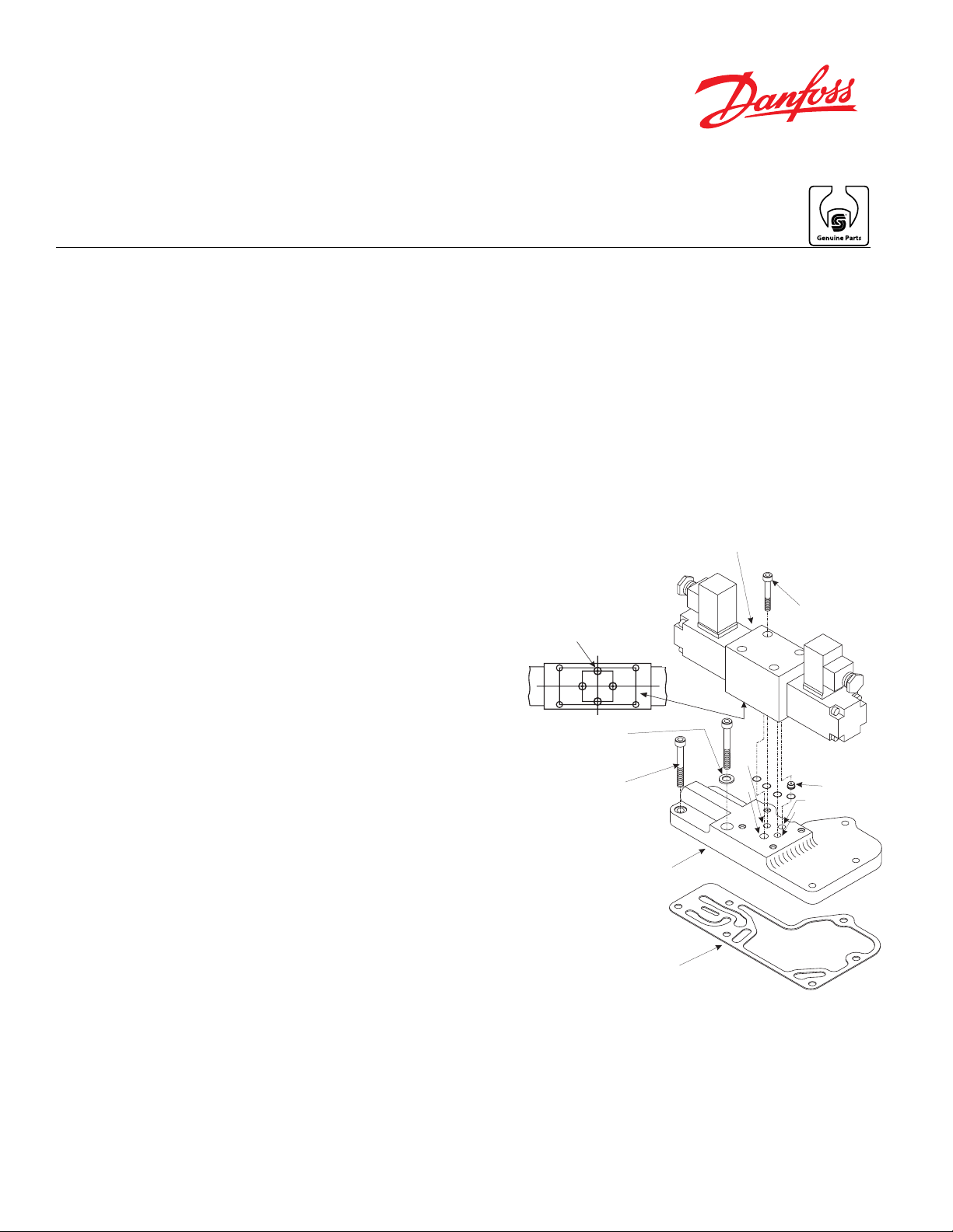
The location of the control passages are noted on the
drawings. ‘P’ is the pilot passage. ‘T’ is the tank (or case
drain) passage. ‘A’ and ‘B’ are the servo control passages
for the respective servos. All FNR’s have the tank orifice
included and need to be installed between the adapter plate
and the solenoid valve assembly, as shown in the drawing.
This tank orifice is installed into the solenoid valve assembly
first, then the O-ring is installed over the orifice, as shown.
Then install the other three O-rings into the solenoid valve
assembly as shown in the picture.
Important Note:
(or case drain) passage, the pressure limiter will
not function properly. See SB-9305 for more details.
If tank orifice is not installed into the tank
Installing the FNR Control Assembly:
The adapter plate must be installed onto the housing first.
If the solenoid valve assembly is assembled onto the
adapter plate first, it will be difficult to get the mounting
screws installed and torque them.
Place the gasket onto the housing. Then place the adapter
plate into position and install the six mounting screws.
Remember to include the seal washer if needed. Torque the
screws to 16 Nm (12 ft•lbf).
Install the solenoid valve assembly onto the adapter plate.
Install the four screws and torque to 5.4 Nm (4 ft•lbf).
Solenoid Valve
Assembly
Torque
P
A
4 ft lbs (5.4 Nm)
Tank Orifice
T
B
Tank Orifice
(included in kit)
A
B
Seal Washer
(Used on 30cc, 42cc,
180cc, & 250cc)
Torque
12 ft lbs (16 Nm)
Some FNR’s utilize orifices in the ‘A’ and/or ‘B’ passages for
the purpose of stroking time in the application. Also, some
Adapter Plate
FNR controls utilize a pilot supply orifice/check valve, which
is located on the bottom side of the adapter plate (pump
housing side). These orifices are not included in this kit. If
they are needed, the “Orifice Group” section of the nomenclature would call these items out.
© Danfoss, 2014 1
BLN-10180 • Rev AA • Apr 2014
Gasket
 Loading...