

Page 1
Installation, start-up
and operating instructions
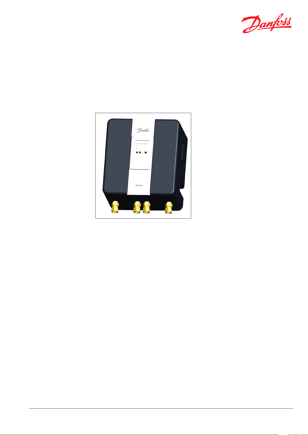
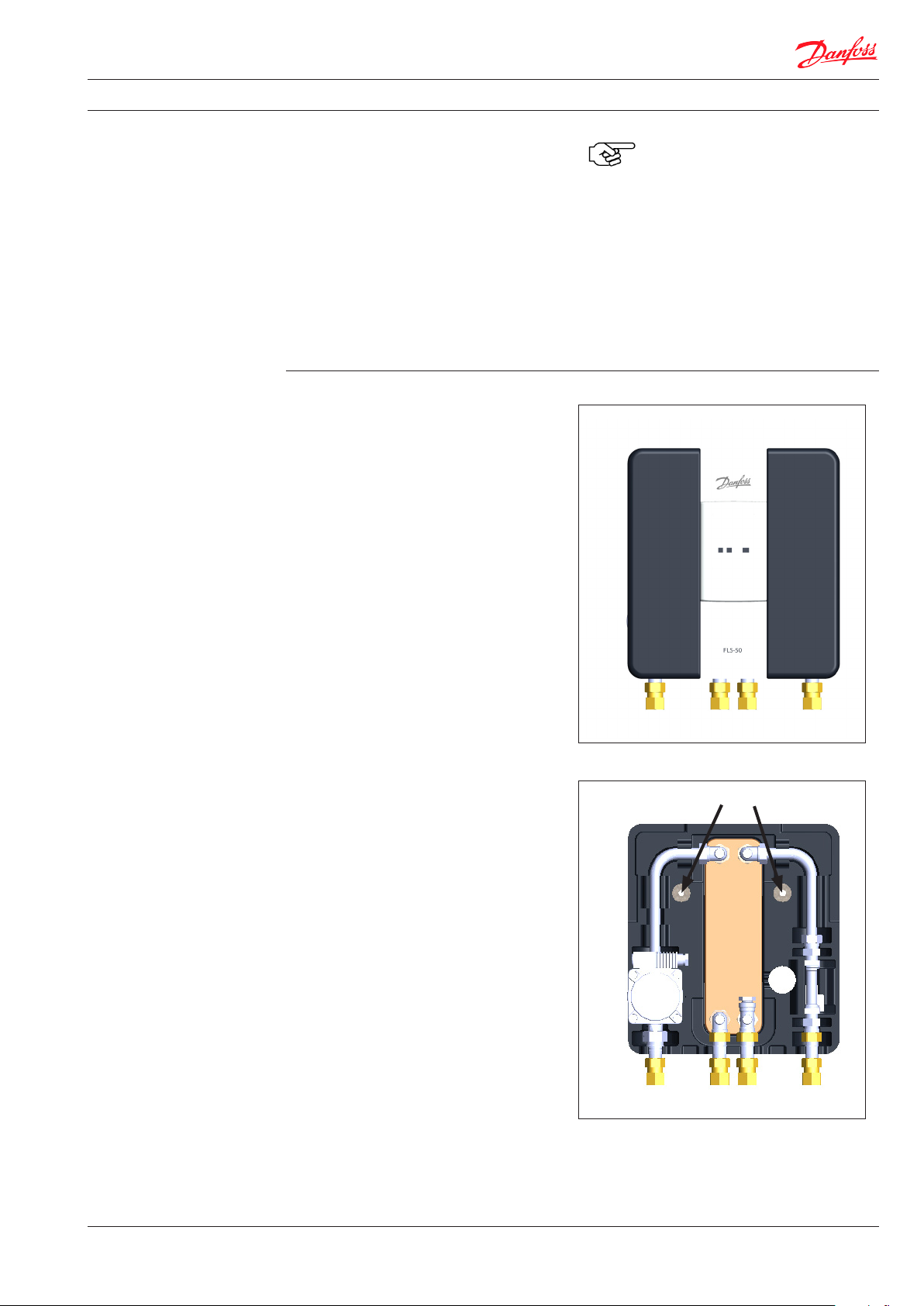
Domestic Water Heater FLS-50
Always keep the operating manual near the
device.
Read the operating manual before commencing
work.
Notice! Before starting the device, make sure
that it is not damaged and that it is in perfect
working order.
DKDHR
VI.GE.T1.02 © Danfoss 12/2010
1
Page 2

Installation, start-up and operating instructions FLS-50
1 General ............................................................................................................................................... 4
1.1 Information about the operating manual ............................................................................................................4
1.2 Supporting documents ...............................................................................................................................................4
1.3 Explanations of the symbols .....................................................................................................................................4
1.4 Warranty and liability ...................................................................................................................................................5
1.5 Copyright ..........................................................................................................................................................................5
1.6 Spare parts .......................................................................................................................................................................6
1.7 Dismantling ......................................................................................................................................................................6
1.8 Disposal .............................................................................................................................................................................6
2 Safety.................................................................................................................................................. 7
2.1 General ..............................................................................................................................................................................7
2.2 Responsibility of the operator ..................................................................................................................................7
2.3 Intended use ...................................................................................................................................................................7
2.4 Possible misuse ..............................................................................................................................................................7
2.5 Occupational safety .....................................................................................................................................................8
2.6 Personal protective equipment ...............................................................................................................................8
2.7 Potential hazards involving the device .................................................................................................................8
2.8 Emergency stop switch ...............................................................................................................................................9
2.9 Operating personnel ....................................................................................................................................................9
2.10 What to do in case of danger or accidents.........................................................................................................9
2.11 Residual hazards/risk analysis .............................................................................................................................. 10
3 Technical data .................................................................................................................................. 11
3.1 Technical and main system data ............................................................................................................................11
3.1.1 Circuit diagram ......................................................................................................................................................11
3.1.2. Bill of materials .....................................................................................................................................................11
3.1.3 Type plate .............................................................................................................................................................. 12
3.1.4 Pressure loss curve ............................................................................................................................................ 12
3.1.5 Capacity examples ............................................................................................................................................. 12
3.1.6 FLS-50 + options ................................................................................................................................................. 12
3.1.7. Dimensions and photo of components ..................................................................................................... 13
4 Function ........................................................................................................................................... 14
4.1 Function / General ...................................................................................................................................................... 14
5 Setup ................................................................................................................................................ 15
5.1 Assembly and installation/general ...................................................................................................................... 15
5.1.1 Figure FLS-50 ........................................................................................................................................................ 15
6 Transport, packing and storage .................................................................................................... 16
6.1 Transport pallets with a fork lift truck .................................................................................................................16
6.2 Transport inspection ................................................................................................................................................. 17
6.3 Packaging ...................................................................................................................................................................... 17
6.4 Storage ........................................................................................................................................................................... 17
7 Installation ....................................................................................................................................... 18
7.1 Assembly preparations ................................................................................................................ 18
7.1.1 Electrical connection .......................................................................................................................................... 18
7.1.2 Assembly of FLS-50 ............................................................................................................................................ 21
7.1.2.1 Assembling the basic device ................................................................................................................... 22
7.1.2.2 Assembling Option 1 ................................................................................................................................. 23
7.1.2.3 Assembling Option 2 ................................................................................................................................. 23
7.1.2.4 Assembling Option 3 ................................................................................................................................. 25
7.1.2.5 Assembling Option 4 ................................................................................................................................. 26
2
VI.GE.T1.02 © Danfoss 12/2010
DKDHR
Page 3

Installation, start-up and operating instructions FLS-50
8 Start-up ............................................................................................................................................ 27
8.1 Controller ....................................................................................................................................................................... 27
8.2 Fault and shutdown................................................................................................................................................... 28
8.3 Restarting after a fault .............................................................................................................................................. 28
9 Operation .........................................................................................................................................28
9.1 Switching the device on ........................................................................................................................................... 28
9.2 Switching the device o ..........................................................................................................................................28
10 Maintenance ..................................................................................................................................29
10.1 Safety information ...................................................................................................................................................29
10.2 Maintenance work ................................................................................................................................................... 30
10.3 Measures after maintenance work ....................................................................................................................30
11 Faults .............................................................................................................................................. 31
11.1 Functional faults ........................................................................................................................................................ 31
11.2 Safety information ................................................................................................................................................... 32
11.3 What to do in case of faults................................................................................................................................... 32
12 Spare parts ..................................................................................................................................... 32
11.3 What to do in case of faults................................................................................................................................... 32
13 Appendix I ...................................................................................................................................... 33
13.1 Exchanger calculations ........................................................................................................................................... 34
13.2 Pressure loss curve, Primary pump .................................................................................................................... 39
13.3 Temperature sensor ................................................................................................................................................40
13.4 Temperature/ow meter .......................................................................................................................................44
13.5 Pressure loss curve, Circulation pump ............................................................................................................. 45
14 Appendix II ..................................................................................................................................... 46
14.1 Declaration of Conformity .................................................................................................................................... 47
DKDHR
VI.GE.T1.02 © Danfoss 12/2010
3
Page 4
Installation, start-up and operating instructions FLS-50
1 General 1.1 Information about the operating manual
This operating manual describes installation,
operation and maintenance of the system.
Compliance with the safety and handling
instructions is a requirement for working safely
and using the system properly.
Apart from this, the local accident prevention
regulations and general safety regulations
applicable where the system is used must also be
observed.
The operating manual is a part of the product
and should be kept accessible near where the
system is operated at all times for installation,
1.2 Supporting documents
If not stated otherwise, the individual system
components are purchased modules from other
manufacturers. All the components used in the
system have been subject to risk assessments by
their manufacturers. The component
manufacturers have declared that the design of
the components complies with applicable
European and national regulations.
The manufacturers' conformity declarations and
the operating, maintenance and repair
1.3 Explanations of the symbols
Important safety and technical information in
this operating manual is marked with warning
signs. The information must be observed to
prevent accidents, injury and damage to
property.
operation, maintenance and cleaning personnel.
The graphics in this manual, which are intended
to provide a better description of the facts, are
not necessarily to scale and may deviate slightly
from the actual system design.
Apart from this operating manual, the operating
instructions for the installed components should
also be observed. The information contained in
these – especially in relation to safety – must be
complied with.
instructions for the individual components are
inseparable elements of the system
documentation. All the instructions on safety,
assembly and installation, operation,
maintenance, dismantling and disposal of the
components contained in the manufacturers'
documentation must be followed by operating
personnel.
NOTICE!
This symbol indicates instructions which, if not
followed, may result in damage,
malfunctions and/or failure of the system.
WARNING!
This symbol indicates hazards that could aect
health or cause injuries, permanent bodily harm
or death.
Observe the instructions on occupational safety
closely and be especially careful in such cases.
WARNING!
Risk of injury from electrical current.
This symbol draws your attention to dangerous
situations involving electrical current. If the
safety instructions are not complied with, there
is a risk of serious injury or death. Work must be
carried out only by a qualied electrician.
NOTE!
This symbol highlights hints that should be
observed to ensure ecient, problem-free
operation of the system.
4
VI.GE.T1.02 © Danfoss 12/2010
DKDHR
Page 5

Installation, start-up and operating instructions FLS-50
1.4 Warranty and liability
All data and information in this operating
manual were compiled with consideration of
applicable regulations, the current technical/
engineering development status and our many
years of knowledge and experience.
The actual scope of delivery may dier from the
explanations and drawings shown here in case of
special designs, if additional options are ordered
or due to recent technical modications. If you
have any questions, please contact the
manufacturer.
1.5 Copyright
The operating manual should be treated as
condential. It is intended only for people
involved with the system. The operating manual
may not be handed over to a third person
without the written consent of the manufacturer.
If you have any questions, please contact the
manufacturer.
This operating manual should be read
carefully before any work is done to and
with the device, especially before it is used for the
rst time. The manufacturer accepts no liability for
damage or faults that result from non-compliance
with the operating manual .
We may make technical modications within the
scope of improving performance characteristics
and in the course of further development.
The warranty does not cover components, such
as tools, that are subject to normal wear when
the device is used as intended or consumables
such as grease, oil or cleaning agents.
In all other respects, the obligations agreed in
the delivery contract shall apply in addition to
the manufacturer's general terms and conditions
of business and terms and conditions of delivery
and the statutory regulations applicable at the
time the contract was concluded.
The information, texts, drawings, pictures
and other presentations are protected by
copyright and are subject to other industrial
property rights. Misuse of the above is indictable.
The content, including excerpts, may not be
copied in any way whatsoever, nor may it be
utilised or disclosed without the written consent
of the manufacturer. Compensation shall be due
in case of infringements of the above. We reserve
the right to assert further claims.
DKDHR
VI.GE.T1.02 © Danfoss 12/2010
5
Page 6
Installation, start-up and operating instructions FLS-50
1.6 Spare parts
Use only the manufacturer's original spare parts.
1.7 Dismantling
To dispose of the device separately, clean it and
dismantle it with consideration of applicable
occupational safety and environmental
protection regulations. See also: Hygiene.
WARNING! Risk of injury.
Stored residual energies, sharp-edged
components, sharp points and edges on
and in the device or on the required tools
may cause injury. Therefore, all work to dismantle
the device must be carried out only by qualied
personnel.
WARNING! Not drinking water!
Domestic water in system
parts that have not been used
for a long period may not
have drinking water quality. Please prevent use,
empty the system parts and dispose of the water .
Wrong or faulty spare parts may cause
damage, malfunctions or complete
failure of the system.
If unapproved spare parts are used,
this voids all warranty, service, compensation
and liability claims against the manufacturer, its
agents, dealers and representatives.
Before starting to dismantle the device:
– Switch the device o and make sure that it
cannot be switched on again.
– Physically isolate the complete power supply
from the device, discharge stored residual
energy properly.
– Remove operating and auxiliary materials and
residual processing materials in an
environmentally friendly manner.
1.8 Disposal
If no return or disposal agreement has been
made, when components have been properly
dismantled dispose of the materials as follows:
• Scrap residual metal materials.
• Have plastic elements recycled.
• Sort and dispose of the other components
according to their properties.
• Dispose of residual media properly. Observe the
statutory regulations when discharging additives
(glycol, etc.).
NOTICE!
Electric scrap, electronic components,
lubricants and other auxiliary materials
are subject to special waste treatment
and may be disposed of only by authorised
specialist companies.
Remove substances such as grease, oil,
preservatives and cleaning agents from the
device separately and in an environmentally
compatible manner. Use approved containers to
catch and keep the respective substances. Until
nal disposal, store containers, clearly marked
with information about the content, level and
date, in such a way that they cannot be misused.
6
VI.GE.T1.02 © Danfoss 12/2010
DKDHR
Page 7

Installation, start-up and operating instructions FLS-50
2 Safety
This section gives an overview
of all important safety aspects
for optimum protection of
personnel and for the safe and
fault-free operation of the
device.
The individual chapters also
contain specic safety
information, marked with
symbols, to prevent direct
hazards.
2.1 General
When it was developed and produced, the
device complied with all applicable,
acknowledged rules of technology and is
deemed to be safe to operate. However, the
device may harbour risks if it was installed by
unqualied personnel or is not used for its
intended purpose. Therefore, every person who
is to work on or with the device must have read
and understood the operating manual before
commencing work. The operator is advised to
have personnel conrm that they acknowledge
the operating manual.
Changes of any type, additions or conversions to
the device are not allowed.
2.2 Responsibility of the operator
• Always keep the operating manual near the
device and make sure that it is accessible at all
times for installation, operating, maintenance
and cleaning personnel.
• Operate the device only in a technically faultless
and safe condition.
• Keep safety features freely accessible at all
times and check them regularly.
Statements regarding occupational safety refer
to the regulations of the European Union
applicable at the time the device was
manufactured. The operator must ensure that
the listed occupational safety measures comply
with the current status of the regulations and
observe new regulations throughout the entire
service life of the device. Outside the European
Union the applicable occupational safety laws
and regional regulations and provisions must be
complied with.
Apart from the occupational safety information
in this operating manual, the general safety,
accident prevention and environmental
protection regulations applicable to the use of
NOTE!
Always coordinate any changes or
extensions with the manufacturer.
All safety, warning and operating instructions for
the device must be kept in a legible condition.
Damaged signs or stickers must be replaced
without delay.
Specied settings and adjustment ranges must
be complied with.
the device must be observed and complied with.
The operator and his authorised personnel are
responsible for fault-free operation of the device
and for clear denition of responsibilities
regarding installation, operation, maintenance
and cleaning of the device.
The information in the operating manual must
be followed completely and absolutely.
The operator must also ensure that
– in a risk assessment other risks arising due to
the particular working conditions at the place
where the device is installed are identied.
– all other work and safety information identied
in the workplace risk assessment is dened in
operating instructions.
– the German Ordinance on Industrial Safety and
Health (BetrSichV, Federal Law Gazette I 2002,
3777) applies.
DKDHR
2.3 Intended use
The operating safety of the device is guaranteed
only if it is used as intended in accordance with
the data in the operating manual.
Intended use also includes correct adherence to
the installation, operation, maintenance and
cleaning instructions.
2.4 Possible misuse
The device is installed inside a system and has no
separate control. With the installation the
operator must ensure that suitable safety
features are available so that the device can be
shut down in case of danger or faults.
VI.GE.T1.02 © Danfoss 12/2010
Any additional and/or other use of the device is not
allowed and shall be deemed to be an unintended
use. Claims of any kind against the manufacturer
and/or his agents due to damage caused by
unintended use of the device shall be excluded. The
operator and/or owner shall be solely liable for all
damage resulting from unintended use .
NOTE!
e.g. Emergency stop button, etc.
7
Page 8
Installation, start-up and operating instructions FLS-50
2.5 Occupational safety
If the instructions on occupational safety are
followed, this can prevent risks for persons and/
or the system.
Non-compliance with these instructions can
result in risks for persons and objects due to
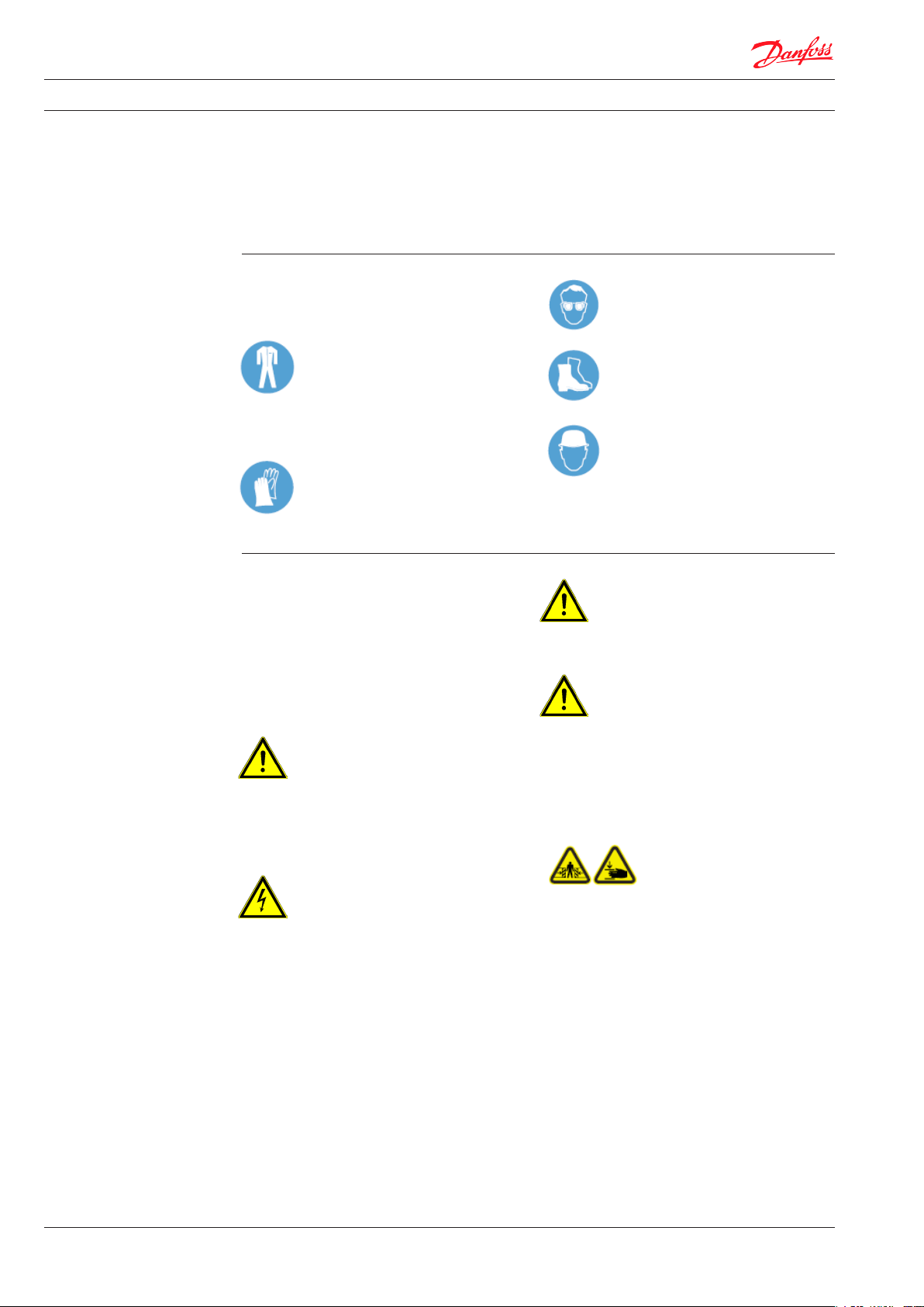
2.6 Personal protective equipment
When working on the device, the following must
be worn:
Industrial protective clothing
is tightly tting work clothing with low
tear resistance, close tting sleeves and
with no protruding parts. Its main
purpose is to protect the wearer when he or she
is reaching into moving parts.
Do not wear rings, chains or other jewellery.
Protective gloves
to protect the hands against friction,
abrasion, puncture wounds or more
serious injuries caused by hot surfaces.
2.7 Potential hazards involving the device
The device was subjected to a risk analysis. The
design and construction of the device based on
this analysis are state of the art.
However, there are residual hazards.
The device generates a strong spray of liquid
when the drainage or ventilation ttings are
opened.
The device works with a pressure of 10 bar.
WARNING! Risk of injury.
Risk of liquid spraying out under high
pressure. Wear personal protective
equipment when carrying out all work on the
device .
The device works with electrical voltages up to
230 V and currents up to 16 A.
WARNING! Risk of injury from electrical
current.
Electrical energies can cause very serious
injuries. There is a danger to life if the insulation or
individual components are damaged.
– Before carrying out any maintenance, cleaning
or repair work, switch o the main switch and
make sure that it cannot be switched on again.
– If work is being carried out on the electrical
system, isolate it from the power supply.
– Do not remove or disable any safety facilities
by altering them.
mechanical eects or failure of the system and
the entire workplace.
Non-compliance with the safety regulations
voids all claims for compensation.
Safety glasses
to protect the eyes against ying
parts and splashes of liquid.
Safety shoes
to protect the wearer against falling
parts and slipping on slippery oors.
Hard hat
to protect the wearer against falling
and ying parts and materials.
WARNING! Risk of injury.
Sharp-edged parts of the housing and
sharp corners can cause skin abrasions.
Wear protective gloves when working on the device.
WARNING! Risk of burning.
Hot surfaces can cause serious burns. Always
wear personal protective equipment when
carrying out all work on the device .
The device works at a maximum temperature of 95°C.
Components in the device may contain
automatic moving parts (motors, gears, etc.).
The devices can be very heavy.
WARNING! Crushing hazard.
When the device is being
transported, also if lifting
equipment is used, crushing can
occur due to the weight. The
device may contain components that move with
electricity (motors, gears) which could also cause
crushing if they are touched during operation.
Always isolate the device and wear protective
clothing when working on the device.
8
VI.GE.T1.02 © Danfoss 12/2010
DKDHR
Page 9

Installation, start-up and operating instructions FLS-50
2.8 Emergency stop switch
The device is installed inside a system and has no
separate control. The operator must ensure that
emergency stop switches in compliance with
applicable accident prevention regulations are
2.9 Operating personnel
The device may be operated and maintained
only by authorised, trained and instructed
personnel. These personnel must have been
instructed especially about potential risks.
An instructed person is deemed to be a person
who has been instructed about the work he or
she has been entrusted with and the potential
risks associated with improper behaviour and, if
necessary, who has been instructed about the
necessary safety features and safety measures.
Trained personnel are deemed to be persons
who, due to their professional training,
knowledge and experience and knowledge of
the relevant regulations, are able to assess the
work they have been entrusted with and
recognise potential risks.
If personnel do not have the required
knowledge, they must be trained.
The responsibilities for operation and
maintenance must be clearly dened and
adhered to so that there is no unclear
distribution of competency under the aspect of
safety.
installed. The operator must prove that he has
informed operating personnel about the
location and functions of the emergency stop
switches.
The device may be operated and maintained
only by persons who can be expected to carry
out their work reliably. The mode of working
must not have an adverse eect on the safety of
persons, the environment or the device. Persons
under the inuence of drugs, alcohol or
medication that slows their reactions may not
carry out any type of work on or with the device.
The choice of personnel must take account of
the national young persons employment laws
and any underlying job-specic regulations.
Operators must also ensure that no unauthorised
persons work on or with the device.
Unauthorised persons, such as visitors etc., may
not come into contact with the device. They
must remain at an appropriately safe distance
from the device.
Users must report changes on the device that
have an adverse eect on safety to the operator
immediately.
2.10 What to do in case of danger or accidents
In case of danger or an accident, switch the
device o immediately with an emergency stop
switch.
Safety features with an emergency stop function
should be activated only in emergency
situations.
Safety features may not be used to switch the
device o under normal conditions.
Always be prepared for accidents or re.
Have rst aid facilities (medical kit, eye rinse
bottles, etc.) and re extinguishers nearby.
Personnel must be condent in the use of and
know the locations of safety, accident reporting,
rst aid and rescue facilities. This ensures that
risks are averted and that the best possible
assistance is given in case of accidents.
DKDHR
VI.GE.T1.02 © Danfoss 12/2010
9
Page 10

Installation, start-up and operating instructions FLS-50
2.11 Residual hazards/risk analysis
Location of hazard Type of hazard Aim of protec tion Measure
Shut-o valves and ttings in
the station
Piping and components in
the station
Complete station Electric shock Safe contact with the station Protection against accidental
Complete station Splashing liquids and/or
Complete station Overheating of the station or
Crushing in case of manual
operation
Can burn the skin if touched Safe contact with open
steam under high pressure
heat transfer to the
connected house system in
excess of the permitted
temperature
Manual operation of the
shut-o valves and ttings
must be possible without
danger.
station
Controlled reduction of
excess pressure in the event
of a fault
Stop heating in case of a fault Safety features acc. to DIN
The design leaves sucient
space for ergonomic
operation.
Thermal insulation of piping
and components
Warning signs at the station
Warning information in the
operating manual
contact
Safety features acc. to DIN
4747 T1 (hot water) and/or
DIN EN 12828
4747 T1 (hot water) and/or
DIN EN 12828
During operation, the residual hazard can be
limited to the following alphabetical value
according to Suva risk assessment: B5/C4/D3/E2.
The residual hazard potential results from
non-compliance with the above operating
instructions. The assemblies were produced
according to the explicit specications of the
operator, who is responsible for compliance with
the specied parameters, selection and
qualication of the operating personnel.
The system is equipped with the following
warning sign, which points out the most
important residual hazards:
The system must be operated only by trained , qualied personnel after they have
studied the enclosed documentation in detail. Before the system is started for the rst
time, it must be lled and completely deaerated. Exceeding the permitted operating
pressure or the maximum permitted operating temperature according to the type plate
or any other use apart from the intended use are not allowed.
Risk of burning from touching the surface or from the emissions of hot media (water/
steam). Avoid touching the assembly or wear suitable protective clothing.
Crushing hazard when operating the assemblies
Risk of electric shock before working on the electrical system, isolate it
All ange connections, screw joints and electrical clamp and screw connections must be
checked and tightened if necessary before the system is lled and put into operation.
Switch pumps on only when they are full (no dry running).
Before starting the system for the rst time, install it professionally (if not
completely assembled in the factory):
• Safety valve/drainage and steam piping according to DIN 4751 and/or DIN 1988
• Strainer in primary supply line/secondary return line
• Potential equalisation acc. to VDE 0100 Part 540 (earthing/earth wires/potential
equalisation)
10
VI.GE.T1.02 © Danfoss 12/2010
DKDHR
Page 11
Installation, start-up and operating instructions FLS-50
3 Technical data
3.1 Technical and main system data
You will nd the main system data on the type
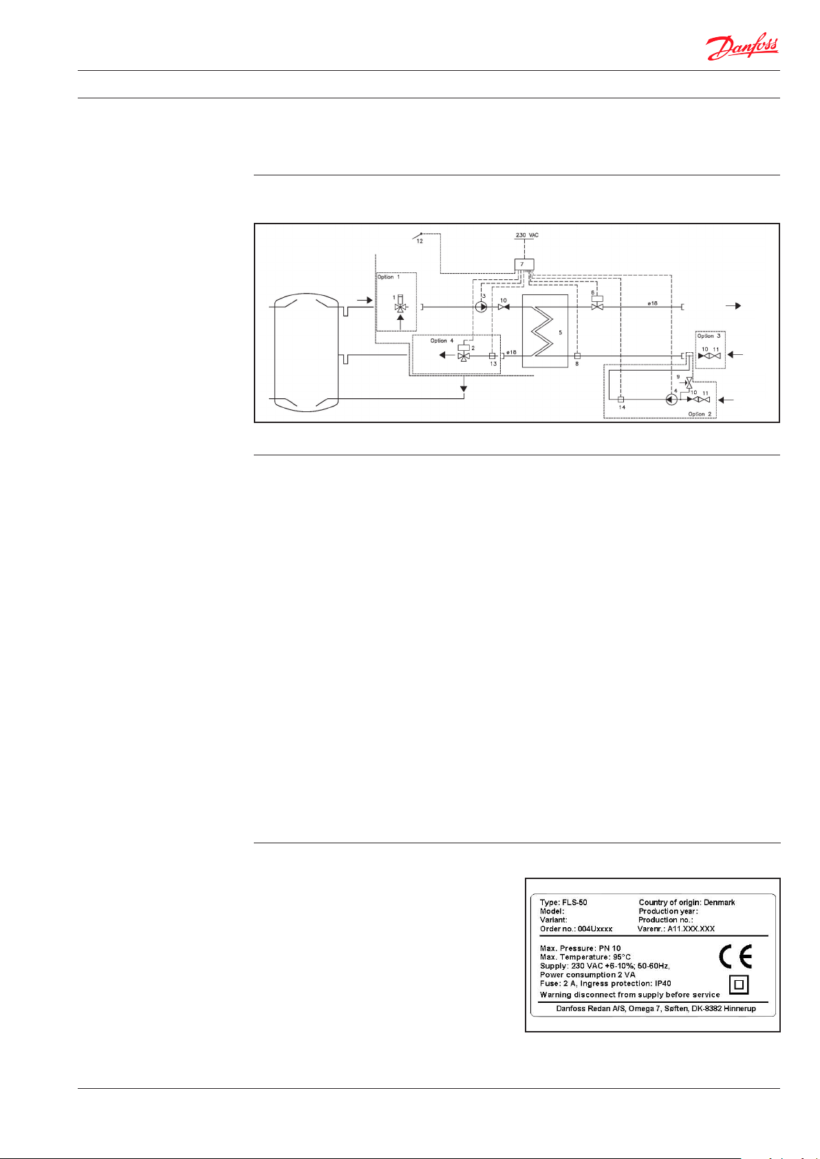
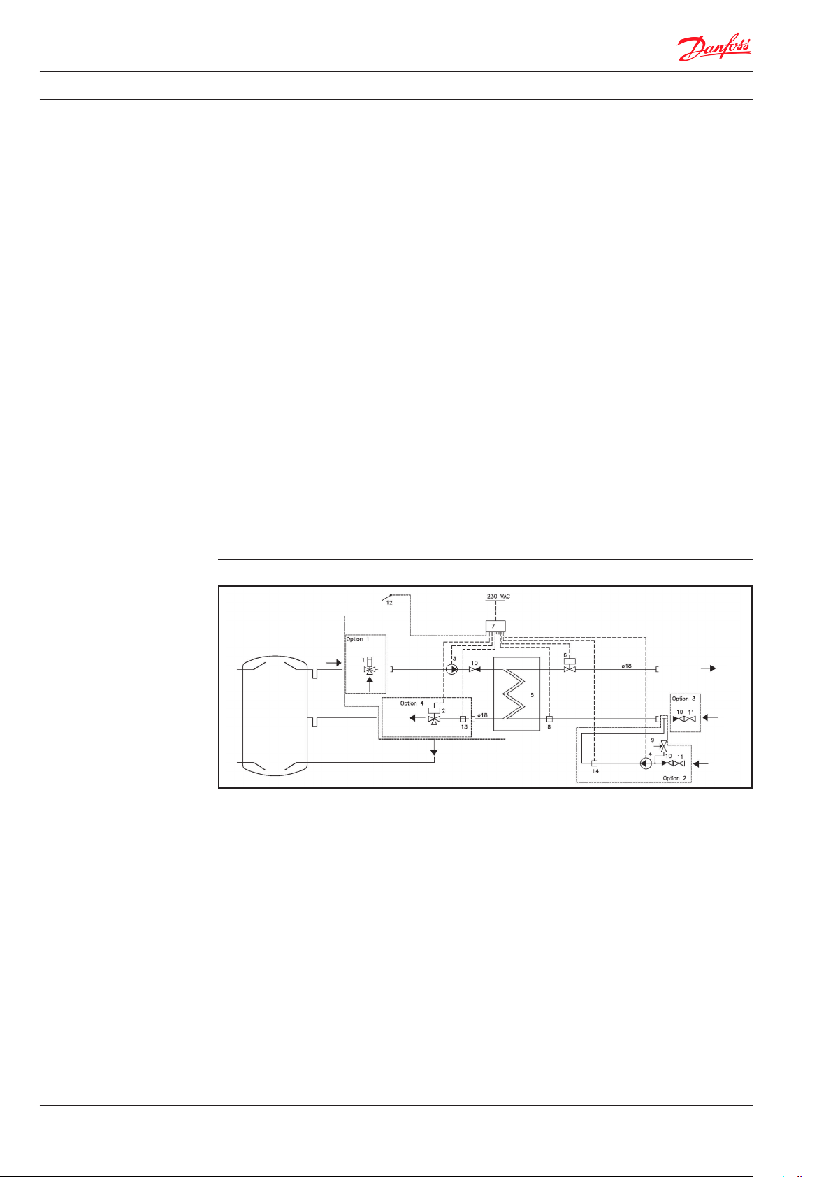
3.1.1 Circuit diagram
Installe d in top buer
tank
Scope of del ivery
Buer tank
Top
Buer tank
Return
Buer tank
Middle
Buer tank B ottom
3.1.2. Bill of materials
1 Three-way mixer valve
2 Three-way valve On/O
3 Pump
4 Pump, circulation
5 Plate heat exchanger
6 Temperature/ow meter
7 Controller
8 Temperature sensor
9 Safety valve
10 Non-return valve
11 Shut-o valve
12 Temperature sensor
13 Temperature sensor
14 Temperature sensor
plate and in the documents in the appendixes
(cover sheet, circuit diagram, data sheet).
CW
¾“
Circ.
¾“
HW
¾“
DKDHR
Optional accessories
Option 1: Temperature control, inlet
Option 2: Circulation
Option 3: Shut-o valves/ball valves
Option 4: Stratication control
3.1.3 Type plate
The type plate is attached to the system.
The type plate contains the following data:
– Manufacturer
– Device no.
– Year of construction (year/calendar week)
– Type
– Power
– Dimensioning parameters
– Max. permissible operating temperature
– Max. permissible operating pressure
– Test pressure
VI.GE.T1.02 © Danfoss 12/2010
Example of type plate
11
Page 12
Installation, start-up and operating instructions FLS-50
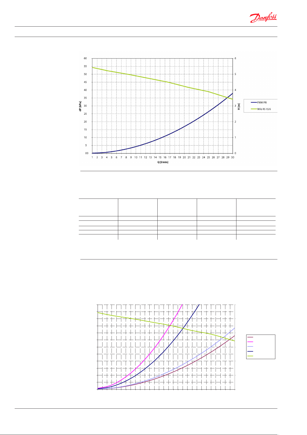
3.1.4 Pressure loss curve
3.1.5 Capacity examples
Capacity examples
HW
Temperature
°C
10/45 20 50 60/20 18
10/45 14 34 50/27 21
10/45 25 60 75/16 15
10/55 18 55 75/20 15
10/55 12 36 60/30 18
* Max. chloride compounds 150 mg/l
HW
Flow rate
l/min.
HW
Power
CW
Supply/Return
Primary
°C
Flow
Primary
l/min.
3.1.6 FLS-50 + Options
When possible options are used the pressure loss ratio changes as shown in the curve below. The
TVM-H 25 mixing valve, among other elements, is recommended for primary-side installation with
service water values with dH > 20. This means a recommended ow temperature of 65°C can be set.
FLS‐50+Optioner
60,00
55,00
50,00
45,00
40,00
35,00
30,00
dP[kPa]
25,00
20,00
15,00
10,00
5,00
0,00
1 2 3 4 5 6 7 8 9 10 11 12 13 14 15 16 17 18 19 20 21 22 23 24 25 26 27 28 29 30
Q[l/min]
6
5
4
3
2
1
0
H[m]
FLS‐50PRI
FLS‐50+Optioner
FLS‐50+AMZ113
FLS‐50+TVM‐H25
WiloRS15/6
12
VI.GE.T1.02 © Danfoss 12/2010
DKDHR
Page 13
Installation, start-up and operating instructions FLS-50
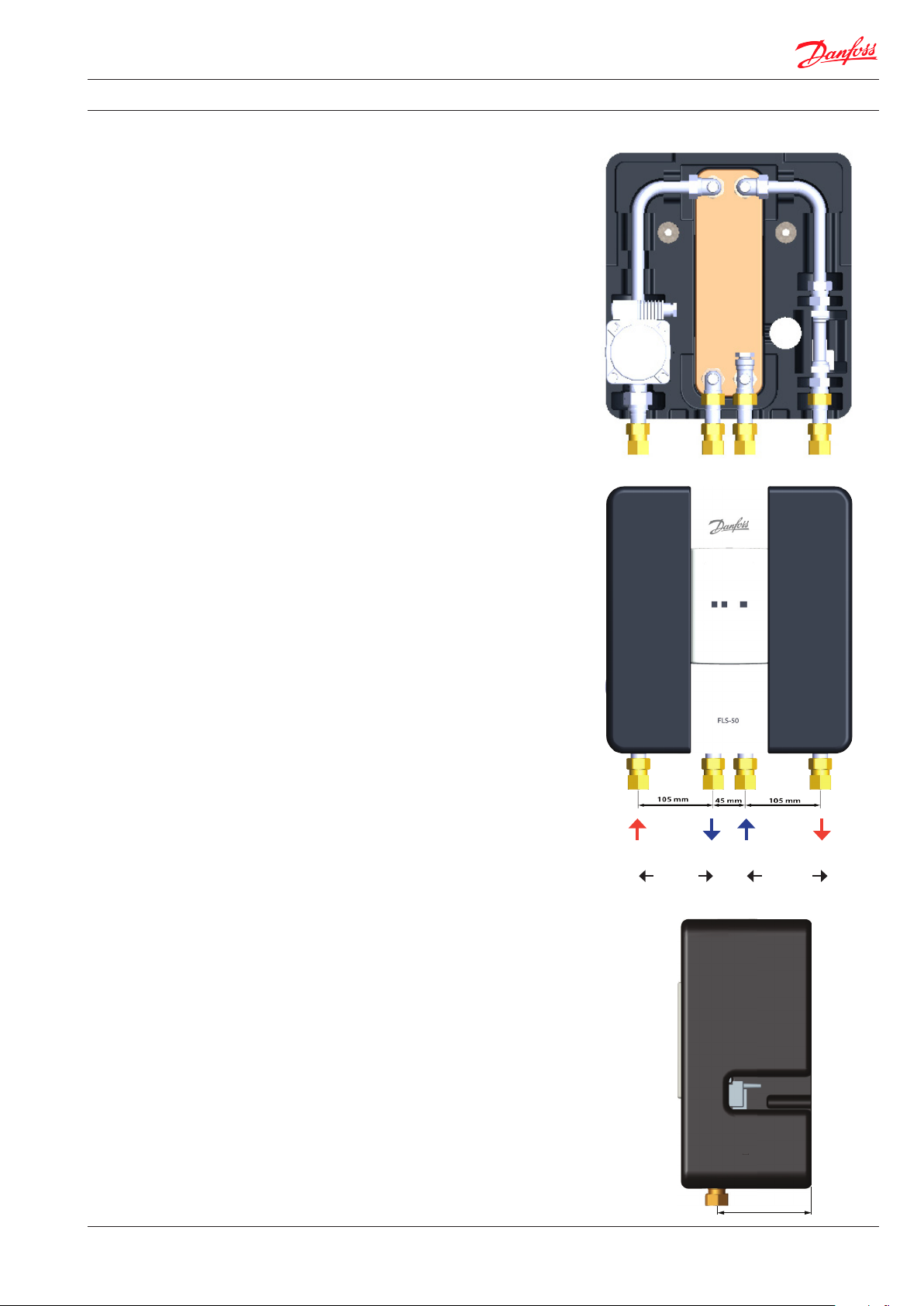
3.1.7 Dimensions and photo of
components
1 Three-way valve (option)
2 Three-way valve On/O (option)
3 Pump
4 Pump, circulation (option)
5 Plate heat exchanger
6 Temperature/ow meter
7 Controller
8 Temperature sensor
9 Safety valve (option)
10 Non-return valve
11 Shut-o valve (option)
10
5
3
6
8
Primary
Supply
Primary
Return
Primary Domestic
7
DHW DCW
hot water
DKDHR
VI.GE.T1.02 © Danfoss 12/2010
130 mm
13
Page 14
Installation, start-up and operating instructions FLS-50
4 Function
4.1 Function / General
The FLS-50 is a domestic hot water heater for a
single household; the water is heated by an
instantaneous water heater
in combination with a buer tank. The hot water
supply and hot water feed to the buer tank can
generally be ensured with solar energy in
combination with other energy sources, such as
oil or gas boilers, district heating or heat pumps.
The instantaneous ow process oers good
protection against Legionella because the
amount of warm water in the heat exchanger is
kept to a minimum. The heat exchanger ensures
an adequate supply of domestic hot water at
supply temperatures from 50°C.
The FLS-50 ensures a constant hot water
temperature, even in case of peak ow and
uctuation supply temperatures, so that the
consuming devices are supplied with sucient
hot water in all operating conditions.
Primary circulation system
The primary side consists of a pump, a nonreturn valve and a temperature sensor.
Secondary circulation system
The secondary side consists of a ow/
temperature sensor on the hot water side and a
temperature sensor at the cold water inlet.
Control
The electronic controller in the FLS-50 ensures a
constant hot water temperature.
The controller receives signals from 3 sensors
that measure the supply temperature in the
primary side in the buer tank, the secondary
ow rate, the cold water inlet and the hot water
outlet. The electronic controller converts these
signals for innitely variable speed control of the
primary side pump that supplies the heat
exchanger with energy from the buer tank as
required.
Options
Options include a primary-side mixer valve, a
primary-side switching valve and sensor, an
installation kit for HW circulation, constant
maintenance of the circulation temperature by
power control of the pump and shut-o and
non-return valves at the CW inlet.
Construction
All pipes are stainless steel with threaded
connections. The entire mechanical construction
is xed in a prefabricated EPP insulated cabinet
by means of a click-in system and thus ensures
stability and easy replacement of spare parts.
The FLS-50 is to be installed vertically on the
buer tank or on a wall next to the buer tank.
Installe d in top buer
tank
Scope of del ivery
Buer tank
Top
Buer tank
Return
1 Three-way valve
2 Three-way valve On/O
3 Pump
4 Pump, circulation
5 Plate heat exchanger
6 Temperature/ow meter
7 Controller
8 Temperature sensor
9 Safety valve
10 Non-return valve
11 Shut-o valve
12 Temperature sensor
13 Temperature sensor
14 Temperature sensor
Buer tank
Middle
Buer tank B ottom
Optional accessories
Option 1: Temperature control, inlet
Option 2: Circulation
Option 3: Shut-o valves/ball valves
Option 4: Stratication control
Circ.
¾“
DHW
¾“
DCW
¾“
14
VI.GE.T1.02 © Danfoss 12/2010
DKDHR
Page 15
Installation, start-up and operating instructions FLS-50
5 Setup
5.1 Assembly and installation/general
Domestic water heater systems are usually
delivered completely piped and wired in a foam
insulated cabinet. All assemblies and
components are xed in the insulated cabinet by
means of a click-in system. System connections
are specied in the data sheet and in these
instructions.
Make sure that the wall has the necessary
load-bearing capacity for the system (including
the weight of the water!).
Examine the prepared connections carefully so
that they can be joined without any tension.
5.1.1 Figure FLS-50
NOTE!
Do not use a pipe wrench on screwed
joints. Use only a suitable spanner.
You will nd pictures of the device below.
DKDHR
VI.GE.T1.02 © Danfoss 12/2010
Assembly holes
15
Page 16

Installation, start-up and operating instructions FLS-50
6 Transport, packing and
storage
WARNING! Danger to life
When the system is being lifted, turned
and lowered there is a risk of serious
personal injury and material damage
from falling parts. Never stand beneath suspended
loads.
Always observe the following safety rules:
– Adapt transport to suit local conditions.
– Use only approved lifting equipment and
lashing gear with adequate load-bearing
capacity.
– Fix the device only on suitable lashing points,
not on protruding machine parts or on rings of
built-on components. Make sure that the
lashing sits securely.
6.1 Transport pallets with a fork lift truck
Packages that are xed on pallets may be
transported by a fork lift truck under the
following conditions:
• The fork lift truck must be designed to carry the
weight of the transport units.
• The driver must be authorised to drive the fork
lift truck.
Lifting:
1. Drive the fork lift truck with the forks
between or beneath the cross pieces of the
pallet.
2. Drive the forks in so far that they protrude
from the other side of the pallet.
3. Make sure that the pallet cannot topple over if
the centre of gravity is not in the middle.
4. Lift the package and start transporting the
pallet.
WARNING! Danger to life
When the pallet is being lifted, turned
and lowered there is a risk of serious
personal injury and material damage
from falling parts. Never stand beneath suspended
loads.
– Ropes and straps must have safety hooks. Do
not use damaged ropes or straps with abraded
areas. Do not place ropes or straps on sharp
edges, do not knot or twist them. Pay attention
to the centre of gravity of the device when
lashing.
– Never lift, swivel or lower loads above people.
– Always take great care and attention when
moving the device.
Transporting with a fork lift truck
16
VI.GE.T1.02 © Danfoss 12/2010
DKDHR
Page 17
Installation, start-up and operating instructions FLS-50
6.2 Transport inspection
Check the delivery for completeness and transport
damage immediately on receipt.
In case of obvious transport damage, do not accept
the delivery or accept it only with provisions.
Record the extent of the damage on the transport
documents/forwarder's delivery note.
6.3 Packaging
The devices are delivered in dierent forms of
packaging.
Packaging may include materials that are added
to the packages as moisture or frost protection
(e.g. silica gel bags, anti-freeze, etc.).
If no other arrangement regarding returning the
packaging material has been made, it remains
with the customer.
NOTE!
The German Packaging Ordinance that
came into eect on 1 December 1991 states that
transport packaging may be returned to the
6.4 Storage
When the packages have been unloaded they
must be stored until they are to be installed with
consideration of the shipping marks.
Packaged machine parts and accessories must
not be unpacked.
The following regulations apply to storage:
– Store in a dry place. Relative humidity:
max. 60 %.
– Make sure that the packages are not stored
outdoors. It must also be ensured that the
oor of the storage room is dry while the parts
are being stored.
Initiate a complaint.
Complain about hidden defects as soon as they
become obvious, as claims for compensation can
be asserted only within the statutory period.
supplier. Our transport packaging may be returned
to your local Danfoss department
as long as we do not incur
any costs. We will not accept transport
packaging that is delivered and not prepaid.
NOTICE!
Packaging must be disposed of in an
environmentally compatible manner and
in agreement with the corresponding
disposal regulations. For this purpose DANFOSS has
signed an agreement with Interseroh AG and
packaging may be deposited at the company's
collection points.
– Protect the packages against direct sunlight.
Storage temperature 15 to 25 °C – store dust
free.
– Avoid mechanical vibration and damage.
– If parts are to be stored for a longer period,
longer than approx. 3 months, the conservation
measures should be checked. In case of
aggressive weather conditions, the
conservation may have to be renewed.
DKDHR
VI.GE.T1.02 © Danfoss 12/2010
17
Page 18

Installation, start-up and operating instructions FLS-50
7 Installation
WARNING! Risk of injury.
Improper installation and assembly can
cause serious injury and/or material
damage. Therefore, installation and
assembly work may be carried out only by qualied
personnel in compliance with the safety
regulations.
Pipe connections are generally:
- Heating connections as weld-on ends
- Flange connections acc. to DIN EN (pressure stages PN 6 … 40)
- Threaded connections acc. to DIN 2999 as female or male threads
- Threaded connections acc. to DIN 2993/ISO 228 as male threads
7.1 Assembly preparations
Before starting assembly, check that all
assemblies and individual parts are complete
and undamaged.
NOTICE!
Damaged components must not be
assembled.
Install only fully intact parts.
7.1.1 Electrical connection
Only a qualied electrician may carry out the
electrical installation of the station in compliance
with all applicable rules and regulations.
The FLS-50 is wired and tested in the factory.
Use only compliant connection parts to connect
the system to the household system. Check
compliance of the connection type, the pressure
stage and the dimension.
Please ensure the following before you begin with
the electrical connection:
• Read the relevant parts in the warning information section.
• The station should be connected to a
230 V AC power supply. The power connection must be carried out in accordance with
ocial regulations.
• The system must be wired and connected
to an external main switch so that it can be
switched o for maintenance, cleaning or repair work.
18
VI.GE.T1.02 © Danfoss 12/2010
DKDHR
Page 19

Installation, start-up and operating instructions FLS-50
Electrical connection
Fresh water controller FWC3
Sensor side
max. 12V
Note
Extra low voltages max. 12VAC/DC
Connection in left terminal compartment
Terminal: Connection for:
S1 PT1000 cold water
(Optional, see below)
S2 PT1000 circulation
S3 PT1000 buer tank opt.
S4 Supply primary opt.
S5 VFS hot water
(yellow wire)
S6 VFS ow l/min
(white wire)
+ VFS +5V DC
(brown wire)
- Bridge sensor -
The PT1000 sensor can be poled
any way.
Power supply side
230VAC
Danger
Power supplies 230VAC 50-60Hz
Connection in right terminal compartment
Terminal: Connection for:
L Power supply outer cable L
N Power supply neutral
conductor N
R1 Fresh water pump L N
Fresh water pump N
R2 Circulation pump L
N Circulation pump N
The earth wire PE is connected to the PE
metal terminal block
Relay R1: Only for controlling the
speed of standard pumps, min.
Note
load 20VA
The sensor earth (S1-S4) and the VFS (green wire) are connected to the sensor terminal
block - .
Sensor1/Cold water: If no sensor is connected, a temperature of 10°C is assumed for the
cold water. See also 11.2 Sensor calibration on Page 22
Sensor mounting S3 contact sensor must be mounted on
the primary return before the switching
valve.
DKDHR
VI.GE.T1.02 © Danfoss 12/2010
19
Page 20

Installation, start-up and operating instructions FLS-50
Electrical connection
Fresh water controller FWC4
Sensor side
max. 12V
Note
Extra low voltages max. 12VAC/DC
connection in left terminal compartment.
Terminal: Connection for:
S1 PT1000 cold water
(Optional, see below)
S2 PT1000 circulation
S3 Primary, return (opt.)
S4 Primary, supply (opt.)
S5 not occupied
S6 0..10 V / PWM
+ not occupied
- Bridge sensor -
Power supply side
230VAC
Danger
Power supplies 230VAC 50-60Hz
Connection in right terminal compartment
Terminal: Connection for:
L Power supply outer cable L
N P o we r su pp ly n eu tra l
conductor N
R1 Fresh water pump L N
Fresh water pump N
R2 Circulation pump L
N Circulation pump N
R3 Valve, return L (opt.)
N Valve, return N (opt.)
The PT1000 sensor can be poled any way
The earth wire PE is connected to the PE
metal terminal block
Relay R1: Only for controlling the
speed of standard pum ps, min.
Note
load 20VA
The sensor earth (S1-S4) is connected to the sensor terminal block - .
The VFS sensor is inserted directly into the slot on the circuit board in the sensor terminal area
Sensor1/Cold water: If no sensor is connected, a temperature of 10°C is assumed for the
cold water. See also 11.2 Sensor calibration.
Sensor mounting S3 contact sensor must be mounted on the primary return before the switching valve.
S4 tank sensor is provided and must be mounted at the top in the buer tank.
AMZ 113 switching valve is provided and must be mounted in the primary return and
connected electrically to the Mate-n-lok.
20
VI.GE.T1.02 © Danfoss 12/2010
DKDHR
Page 21

Installation, start-up and operating instructions FLS-50
7.1.2 Assembly of FLS-50
The device may be installed and connected only
by authorised personnel. Installation must be in
compliance with the local standards and
regulations.
The FLS-50 must be equipped with features that
ensure that the device can be separated from all
energy sources.
When the device is being installed, attention
must be paid that the domestic water heater
remains accessible for assembly and
maintenance work.
All pipes and connections must be cleaned and
rinsed before installing the domestic water
heater
IMPORTANT! Tighten all screws and connections
since they may have become loose during
transport.
The water heater is intended for wall installation.
Fix the station to the wall with two bolts, screws,
expansion plugs or similar.
With systems with a safety valve, a connection
for drainage must be constructed in accordance
with local regulations.
Assembly holes
24
All pipe connections have
a thread ex factory
Earth:
H 375 x W 345 x D 250 mm
Connections:
1 Primary supply,
2 Primary return
3 DCW supply
4 DHW supply
Connection dimensions:
All connections: G¾ (IG)
Weight: Approx. 11 Kg
1 2 3 4
DKDHR
VI.GE.T1.02 © Danfoss 12/2010
21
Page 22

Installation, start-up and operating instructions FLS-50
7.1.2.1 Assembling the basic
device
The station is delivered in a foam insulated
cabinet - as a click-in system. The station is
installed in the bottom part of the insulated
cabinet.
Please note:
The buer tank temperature sensor is
delivered separately and has to be installed
on site and be connected to the controller.
3 m cable for the buer tank temperature
sensor is preinstalled in the controller
1) Install the temperature sensor (delivered
separately) at the top of the buer tank.
2) Install cable (preinstalled from controller)
from the station to the temperature sensor.
3) Connect the temperature sensor to the
cable.
4) Connect the power socket (Schuko) to
230 V AC.
22
VI.GE.T1.02 © Danfoss 12/2010
DKDHR
Page 23

Installation, start-up and operating instructions FLS-50
7.1.2.2 Assembling Option 1
Primary mixer valve
7.1.2.3 Assembling Option 2
Circulation
The TVM-H is an automatic three-way mixer
valve with inbuilt thermostat to maintain
and ensure a constant temperature.
For further information, see the
enclosed operating instructions
TVM-H / TVM-W.
A complete circulation kit is available as an
option for connecting a circulation system:
Gasket ¾" 24 x 17.5 x 3 mm (145.056) (1)
Circulation kit, complete (oem. 134.102) (2)
Gasket ¾" 24 x 17.5 x 3 mm (145.056) (1).
2
1
1
DKDHR
Installing the circulation kit:
• Dismantle the double socket joint
(in Point A).
VI.GE.T1.02 © Danfoss 12/2010
A
2
1
1
23
Page 24

Installation, start-up and operating instructions FLS-50
• Install the gasket and circulation kit in
Point A.
• Replace the double socket joint and the
gasket (in Point B).
Connect the temperature sensor to the
controller in terminal S2 and minus (÷).
A
2
B
24
Connect the pump to the controller in
terminal R2, neutral and to the earth.
VI.GE.T1.02 © Danfoss 12/2010
DKDHR
Page 25

Installation, start-up and operating instructions FLS-50
7.1.2.4 Assembling Option 3
Non-return valve and shut-o
valve
The non-return valve and the ball valve can
be installed directly on the station (see
Photo 1) (please note: dismantle the double
socket joint in Point A before installing the
non-return valve and the ball valve), or on
the circulation kit (see Photo 2).
Gasket ¾" 24 x 17 x 1 mm (171.040) (1)
Non-return valve (135.120) (2)
Gasket ¾" 24 x 17 x 1 mm (171.040) (1)
Ball valve ¾" M/N (131.055) (3)
A
1
2
1
3
Photo 1
Photo 2
DKDHR
VI.GE.T1.02 © Danfoss 12/2010
25
Page 26

Installation, start-up and operating instructions FLS-50
7.1.2.5 Assembling Option 4
In this version the station is built
with the Sorel FWC 4 Controller.
Cables for the switching valve
and the sensors have to be wired
on site.
The AMZ 113 is a three-way switching valve
for optimum zone control.
For further information, see the
enclosed operating instructions
AMZ 113.
Connect the controller in terminal S3 and
minus (÷).
Datablad ON/OFF Zoneventiler
Anvendelse
Anlægseksempler
2-vejs type AMZ 112
3-vejs type AMZ 113
2-vejs zoneventil AMZ 112 anvendes i
centralvarme- og fjernvarmeanlæg til ON/
OFF regulering af enkelte eller flere varme/
køleflader.
Begge motorer kan styres af et SPST kontaktsæt med sluttefunktion eller en SPDT
skiftekontakt. Motorerne er desuden forsynet med endestopkontakt til signal eller til start af
pumpe, blæser eller kedel ved helt åben ventil. Der er mulighed for manuel betjening.
Ventiler leveres med indvendigt gevind i str. DN 15, 20 og 25.
RA 2000 RA 2000
Zonestyring af radiatoranlæg
Styring af fastbrændsel i forbindelse med kedel Prioritetsstyring af varmtvandsbeholder
VD.HC.N1.01 © Danfoss 11/03 1
3-vejs zoneventil AMZ 113 er en skifteventil,
der anvendes til fordeling af vandstrømme i
f.eks kedelanlæg i forbindelse med
fastbrændselskedel e ller til pri oritetsstyring.
TP7000 M/A
AMZ 112
Zonestyring af varmeblæsere
VVS-automatik 9.10.00
AMZ 112
RA 2000
26
Connect the three-way valve to the
controller in terminal R3, neutral L
and to the earth.
VI.GE.T1.02 © Danfoss 12/2010
DKDHR
Page 27

Installation, start-up and operating instructions FLS-50
8 Start-up The following measures must be carried out:
– The rst time the device is used (see appendix,
Start-up log)
– When the device is restarted after complex
maintenance work has been carried out
– When the device is restarted after having
been relocated
– When the device is restarted after a fault has
been rectied.
– When the device is restarted after it has not
been used for a long period
– Check the water quality. Max. 150 mg/l
Before start-up check that all safety regulations
have been observed.
Fill the household system with domestic water.
To prevent damage, make sure that when the
system is being lled the pressure does not
exceed the permitted operating pressure.
8.1 Controller
The electronic controller is set in the factory.
Connect the controller to the power supply.
Select the language, set the date and time and
the controller is
ready for operation.
NOTE!
Pay attention to the measures required to
maintain domestic water quality. Important
information can be found in the technical rules (see
overview of regulations in the Appendix).
By agreement, the device is installed and started
up for the rst time by the manufacturer's
employees, authorised partner companies or the
specialist installation company.
Customers must not start the device for the rst
time on their own.
In any case, the completed start-up log (see
appendix) is a requirement for the device
warranty.
Before the rst start-up, the installation company
should rinse the secondary side adequately.
Check that all connections are sealed and joined
properly.
Fill the system to the required static height.
SPECIAL WARNING!
If a circulation kit is connected, you must
select menu item 5.4 "Circulation On" to switch on
the circulation pump.
Changes to the settings can be made according
to the controller manufacturer's instructions,
which are enclosed with the station.
DKDHR
VI.GE.T1.02 © Danfoss 12/2010
27
Page 28

Installation, start-up and operating instructions FLS-50
9 Operation
The system is operated in
automatic mode. During
operation no personnel are
needed near the system.
8.2 Fault and shutdown
WARNING! Risk of injury from electrical
current.
Leaking water can make the entire
system live, which can endanger life.
Before starting work, isolate the system and make
sure that it cannot be switched on again.
WARNING! Risk of burning.
In case of leaks on the primary side, water
at temperatures up to 95°C can escape.
Risk of burning.
8.3 Restarting after a fault
After a fault, the system is restarted
by the specialist company.
9.1 Switching the device on
To switch the device on, pay attention to the
requirements described in Section 8 " Start-up".
9.2 Switching the device o
The device is switched o at the main switch of
the electronic controller.
The heating pump is connected to the
power supply.
Immediately switch o the main switch or
remove the plug.
Close the shut-o tting.
It is important that you have a specialist
company rectify the fault.
The system can be switched on at the main
switch of the electronic controller and then it
operates automatically.
28
VI.GE.T1.02 © Danfoss 12/2010
DKDHR
Page 29

Installation, start-up and operating instructions FLS-50
10 Maintenance
10.1 Safety information
The appendix contains an overview of the most
WARNING!
Work on the device may be carried out
only by qualied, specially trained
personnel.
The following personal protection equipment must
always be worn close to the device:
– Close tting clothing (no loose sleeves,
rings, etc.)
– Safety glasses to protect the eyes against
ying parts and liquids
– Safety shoes to protect the wearer against
falling parts and slipping on slippery oors.
WARNING! Risk of injury from electrical
current.
Only qualied electricians may work on
electrical systems observing
the applicable safety regulations.
Before starting work, switch of the power supply
and make sure that it cannot be switched on again.
Maintenance schedule (recommendations)
Interval Maintenance work Comments
Check all connections tighten if necessary and/or replace gaskets
Check all parameters for set/target values and
permissibility
General visual check of all components for
damage
Check the functions of the safet y valve see also DIN 1988
Every 12 months
Check the functions of electric and elec tronic
components, switches, etc.
Clean lters and strainers see also DIN 1988
Check the electric safety features Temperature monitor and/or limiter
Check all components for function and
operability
Check outer condition Colouring (rust), thermal insulation
important technical regulations. For maintenance
of the system you will nd information especially
in DIN 1988, VDI 2895 and VDI 6023.
We recommend that you arrange for a local
installation company to service the system
regularly.
Section 10.2 contains the most important
measures for specic components and
assemblies.
The appendix also contains the corresponding
maintenance and operating instructions for
individual components that should be observed.
In case any are exceeded: Restore the proper
parameters
in case of obvious damage, check the
functions and replace if necessary
Manual switching on and o and opening and
closing of motor drive systems
e.g. open and close shut-o ttings
DKDHR
SPECIAL WARNING!
After maintenance work has been carried
out, all EPDM gaskets should be replaced.
VI.GE.T1.02 © Danfoss 12/2010
29
Page 30

Installation, start-up and operating instructions FLS-50
10.2 Maintenance work
The main jobs that should be carried out within
the scope of maintenance are described below.
Additional information can be found in the
manufacturers' instructions in the appendix.
This list is not complete. In any case, it is
important that the statutory and other relevant
technical regulations and requirements based on
local conditions are observed (e.g. TABs, power
company regulations, etc.)
Fittings:
Generally, the ttings used are maintenance free.
Within the scope of maintenance work the
functions should be checked in terms of
moveability of hand wheels and levers by
opening and closing them.
This prevents dirt and calcium residues settling
on balls, valve discs and valve seats. In Appendix
I you will nd the manufacturers' instructions for
the most common components.
Heat exchanger:
After long operation, because of the relatively
high temperatures the plates or tubes of heat
exchangers are especially subject to calcication.
Within the scope of the above maintenance work
these should be cleaned if there is a reduction in
power. Brazed plate heat exchangers can be
rinsed. In case of more serious deposits, weak
inhibited acid solutions (e.g. 5% formic, acetic or
phosphoric acid) may be used.
The drawing shows this arrangement:
Rinsing/cleaning brazed plate heat exchangers
Tank:
Appendix 1 (No. 3) contains information about this.
10.3 Measures after maintenance work
After maintenance work and before switching
the device on again, remember:
– Check that all screwed connections are tight.
– Check that all safety features, covers, tank lids
that were removed have been replaced
properly.
– Make sure that all tools, materials and other
equipment that were used have been
removed from the working area.
Tubes:
The tubes used are made from high-quality
stainless steel. If they are contaminated, they can
be treated like the tank.
– Clean the working area and remove any
spilled materials, such as liquids, processing
material.
– Make sure that all safety features on the
device and the system work properly.
30
VI.GE.T1.02 © Danfoss 12/2010
DKDHR
Page 31

Installation, start-up and operating instructions FLS-50
11 Faults
Faults in electrical systems or
in mechanical or hydraulic
components may be repaired
only by specially trained and
qualied personnel.
In case of faults that cannot be
rectied with the following
measures, notify the
manufacturer or an authorised
service partner.
11.1 Functional faults
Fault Possible cause Rectifying the fault Comment
Domestic hot water
temperature too
low
Water hygien e at
risk!
Domestic hot water
temperature too
high
Risk of sc alding.
Domestic hot water
temperature
uctuates or is not
constant
Risk of sc alding.
Medium leaking
Risk of sc alding.
No power - Switch on the main switch - Check
No water supply
- no cold water pressure
Incorrec t controller setting(s) Correct settings Controller instructions
Closed shut-o tting(s) Open tting
Defective sensor Replace sensor
Supply pump defective or not
switched on
Circulation pump defective or
not switched on
Defective VFS valve Clean/ensure smooth operation or
System wrongly dimensioned - Check dimensioning
System unable to provide
sucient water
Heat exchanger furred up Replace heat exchanger
Cavitation on the pump Increase primary system pressure Pump makes noises
- No
power supply
- Electric drive open
Incorrec t controller setting(s) Correct settings Controller instructions
Defective sensor Replace sensor
Defective VFS valve Clean/replace valve
Incorrec t controller setting(s) Correct settings
Pump defec tive Replace pump
Leaking connections (ange/
screw joints)
Leaking ttings (housing/screw
joints)
- Leaks from brazed
heat exchangers
- Contamination/calcication
Pressure surges
the inlet lines
- Check fuses/circuit breaker
Operating conditions - Pressure Volume
Switch on/replace
Switch on/replace
replace
- Extend/enlarge system
- Check dimensioning
- Extend/enlarge system
- Take system out of op eration
- Ensure power supply
- Manual emergency operation
- Controller gain
- Reset time
- Valve travel time
Switch system o
- Check operating parameters for
permissibility
(see type plate)
- Check connection, tighten
if necessary, replace gaskets
- Check that t tings are installed
correctly - Tighten stung (gasket)
sleeves or replace component
Replace device See manufacturer's
Water supplier
Contact our exper t advisors
Controller instructions
See manufacturer's
instructions or contact
customer service
instructions or contact
customer service
DKDHR
VI.GE.T1.02 © Danfoss 12/2010
31
Page 32

Installation, start-up and operating instructions FLS-50
11.2 Safety information
WARNING!
If faults are not rectied properly, this can
lead to serious injury and/or
material damage Therefore, faults may be
rectied only by trained and
authorised personnel.
12 Spare parts
11.3 What to do in case of faults
In all cases:
1. In case of faults that represent a direct danger
for people, property and/or operating safety,
immediately stop the system with the
emergency stop function.
2. In case of faults that do not cause such
dangers, switch the system o using the
system controls, also interrupt the power
supply to the system and make sure that it
cannot be switched on again.
Use only the manufacturer's original spare parts.
NOTICE!
Wrong or faulty spare parts and
components from third-party
manufacturers can cause serious
damage, incorrect functions or complete failure of
the device.
If unapproved spare parts are used, this voids all
warranty, service, compensation and liability
claims against the manufacturer, its agents,
dealers and representatives.
When ordering spare parts, you must provide:
– Device type
– Serial/Production No.
– Part No. /Article Number (see bill of materials
circuit diagram)
3. Immediately notify the person responsible
about the fault.
4. Have the type and scope of the fault identied
by authorised, qualied personnel, determine
the cause of the fault and have it rectied.
– Quantity
– Name
– Required form of delivery (post, freight, sea,
air, express)
– Shipping address
– If necessary, a sketch or photo with comments
Orders for spare parts without the above
information cannot be handled. If no information
about the type of shipping is provided, the parts
will be delivered according to the supplier's
preference.
Appendix I also contains a list of the most
important suppliers of bought-in components,
where spare parts can also be requested after
the end of the warranty period . In these cases,
also notify the manufacturer about the installed
parts in detail, so that equal replacements can be
oered.
32
VI.GE.T1.02 © Danfoss 12/2010
DKDHR
Page 33

Installation, start-up and operating instructions FLS-50
13 Appendix I
DKDHR
VI.GE.T1.02 © Danfoss 12/2010
33
Page 34

Installation, start-up and operating instructions FLS-50
13.1 Heat exchanger calculations
34
VI.GE.T1.02 © Danfoss 12/2010
DKDHR
Page 35

Installation, start-up and operating instructions FLS-50
DKDHR
VI.GE.T1.02 © Danfoss 12/2010
35
Page 36

Installation, start-up and operating instructions FLS-50
36
VI.GE.T1.02 © Danfoss 12/2010
DKDHR
Page 37

Installation, start-up and operating instructions FLS-50
DKDHR
VI.GE.T1.02 © Danfoss 12/2010
37
Page 38

Installation, start-up and operating instructions FLS-50
38
VI.GE.T1.02 © Danfoss 12/2010
DKDHR
Page 39

Installation, start-up and operating instructions FLS-50
13.2 Pressure loss curvePrimary pump
DKDHR
VI.GE.T1.02 © Danfoss 12/2010
39
Page 40

Installation, start-up and operating instructions FLS-50
13.3 Temperature sensor
40
VI.GE.T1.02 © Danfoss 12/2010
DKDHR
Page 41

Installation, start-up and operating instructions FLS-50
DKDHR
VI.GE.T1.02 © Danfoss 12/2010
41
Page 42

Installation, start-up and operating instructions FLS-50
42
VI.GE.T1.02 © Danfoss 12/2010
DKDHR
Page 43

Installation, start-up and operating instructions FLS-50
DKDHR
VI.GE.T1.02 © Danfoss 12/2010
43
Page 44

Installation, start-up and operating instructions FLS-50
13.4 Temperature/ow meter
44
VI.GE.T1.02 © Danfoss 12/2010
DKDHR
Page 45

Installation, start-up and operating instructions FLS-50
13.5 Pressure loss curve
- circulation pump
DKDHR
VI.GE.T1.02 © Danfoss 12/2010
45
Page 46

Installation, start-up and operating instructions FLS-50
14 Appendix II
46
VI.GE.T1.02 © Danfoss 12/2010
DKDHR
Page 47

Installation, start-up and operating instructions FLS-50
14.1 Declaration of Conformity
DKDHR
VI.GE.T1.02 © Danfoss 12/2010
47
Page 48

Installation, start-up and operating instructions FLS-50
48
Danfoss A/S
District Energi Division
Omega 7, Søften
DK-8382 Hinnerup
Telephone: +45 87 43 89 43
Fax: +45 87 43 89 44
heating@danfoss.com
www.dh.danfoss.com
VI.GE.T1.02 © Danfoss 12/2010
DKDHR
 Loading...