

Page 1

Installation, commissioning and operation manual
Instantaneous water heater
Thermodual FLS
Always keep the instructions for use readily available near the device.
Read the instructions for use before starting any work!
Caution!
Caution! Before putting the device into service, check that
it is undamaged and in perfect operating condition.
© Danfoss | 2019.08
Original operating instructions
VI.MPJ3.02 | 1
Page 2

ThermoDual FLS
1.0 General Information ...................................................................................................................................................................... 3
1.1 Information on operating instructions .............................................................................................................................................................................. 3
1.2 Other applicable documents ................................................................................................................................................................................................ 3
1.3 Explanation of symbols ........................................................................................................................................................................................................... 3
1.4 Liability and warranty .............................................................................................................................................................................................................. 4
1.5 Copyright ...................................................................................................................................................................................................................................... 4
1.6 Spare parts ................................................................................................................................................................................................................................... 4
1.7 Dismantling ................................................................................................................................................................................................................................. 4
1.8 Disposal ......................................................................................................................................................................................................................................... 5
2.0 Safety .. ............................................................................................................................................................................................................................................. 6
2.1 General Information ................................................................................................................................................................................................................. 6
2.2 Responsibility of the operator .............................................................................................................................................................................................. 6
2.3 Intended use ............................................................................................................................................................................................................................... 6
2.4 Possible misuse .......................................................................................................................................................................................................................... 7
2.5 Occupational health and safety ........................................................................................................................................................................................... 7
2.6 Personal protective equipment ............................................................................................................................................................................................ 7
2.7 Possible hazards of the device .............................................................................................................................................................................................. 8
2.8 Emergency stop switch ........................................................................................................................................................................................................... 8
2.9 Operating personnel ................................................................................................................................................................................................................ 9
2.10 Actions in the event of danger or accidents .................................................................................................................................................................... 9
2.11 Residual hazards / hazard analysis ...................................................................................................................................................................................... 10
3.0 Technical Data ............................................................................................................................................................................................................................. 11
3.1 Technical and main system data .......................................................................................................................................................................................... 11
3.1.1 CE label .................................................................................................................................................................................................................................. 11
3.1.2 Legend and designations ............................................................................................................................................................................................... 11
4.0 Function .......................................................................................................................................................................................... 12
5.0 Setup and Installation ................................................................................................................................................................... 14
5.1 Setup and assembly / General information ..................................................................................................................................................................... 14
6.0 Transport, Packing and Storage ................................................................................................................................................... 16
6.1 Transporting pallets with a forklift ...................................................................................................................................................................................... 16
6.2 Transport inspection ................................................................................................................................................................................................................ 17
6.3 Packing .......................................................................................................................................................................................................................................... 17
6.4 Storage .......................................................................................................................................................................................................................................... 17
7.0 Installation .................................................................................................................................................................................................................................... 18
7.1 Installation preparation ........................................................................................................................................................................................................... 18
7.2 Primary connection, heating medium (e.g. district heating) ..................................................................................................................................... 18
7.3 Secondary connection, domestic water ............................................................................................................................................................................ 18
7.4 Electrical connection ................................................................................................................................................................................................................ 18
7.4.1 Electrical connection of electronic controller ......................................................................................................................................................... 19
7.5 Installation of the system ........................................................................................................................................................................................................ 21
7.6 Installation of thermal layering option and buffer tank charging ........................................................................................................................... 21
8.0 Commissioning ........................................................................................................................................................................................................................... 22
8.1 Requirements for commissioning ....................................................................................................................................................................................... 22
8.2 Requirements for commissioning, domestic water system ....................................................................................................................................... 22
8.3 Primary-side commissioning ................................................................................................................................................................................................. 22
8.4 Controller ....................................................................................................................................................................................................................................... 23
8.5 Malfunction or taking out of service .................................................................................................................................................................................. 23
8.6 Recommissioning after a fault .............................................................................................................................................................................................. 23
8.7 Danfoss controller default settings ..................................................................................................................................................................................... 23
8.7.1 Basic settings ....................................................................................................................................................................................................................... 23
8.7.2 Pump settings ..................................................................................................................................................................................................................... 24
9.0 Operation ...................................................................................................................................................................................................................................... 25
9.1 Switching on ............................................................................................................................................................................................................................... 25
9.2 Switching off ............................................................................................................................................................................................................................... 25
9.3 Recommissioning ...................................................................................................................................................................................................................... 25
9.4 Hygiene and thermal disinfection ....................................................................................................................................................................................... 25
10.0 Servicing ........................................................................................................................................................................................................................................ 26
10.1 Safety instructions / Maintenance schedule (recommendations) ........................................................................................................................... 26
10.2 Maintenance tasks ..................................................................................................................................................................................................................... 27
10.3 Actions after maintenance tasks .......................................................................................................................................................................................... 27
11.0 Disturbances ................................................................................................................................................................................................................................ 28
11.1 Malfunctions ................................................................................................................................................................................................................................ 28
11.2 What to do when faults occur ............................................................................................................................................................................................... 29
12.0 Spare parts ..................................................................................................................................................................................... 29
Index ........................................................................................................................................................................................................... 30
Annex ............................................................................................................................................................................................................................................. 31
Layout / Part locations ....................................................................................................................................................................................................................... 31
HUBA Control flow sensor DS 210 ................................................................................................................................................................................................. 32
Wiring diagram ..................................................................................................................................................................................................................................... 34
Declaration of Conformity (original English and German versions) .................................................................................................................................. 40
Manufacturer’s Declaration (original English and German versions) ............................................................................................................................... 44
2 | © Danfoss | 2019.08
VI.MP.J3.02
Page 3

ThermoDual FLS
1. General Information
1.1 Information on operating instructions
These operating instructions describe the installation, operation
and maintenance of the system. Compliance with all specified
safety instructions and operating instructions is a prerequisite
for working safely with the system and handling it properly. In
addition, the local accident prevention regulations and general
safety regulations applicable to the system’s area of use must be
observed. The operating instructions are part of the product and
must be kept accessible to installation, operating, maintenance
and cleaning personnel at all times in the immediate vicinity of the
system’s operating area.
1.2 Other applicable documents
Unless otherwise stated, the individual components of the system
are modules purchased from other manufacturers. All components
used in the system have been subjected to risk assessments by their
manufacturers. The conformity of the designs with the applicable
European and national regulations has been declared by the
manufacturers of the components. The manufacturers’ declarations
of conformity, as well as the operating, maintenance and repair
For better presentation of the described situations, the illustrations
in this manual are not necessarily to scale and may differ slightly
from the actual design of the system. In addition to these operating
instructions, the operating instructions for the installed components
apply. The information contained therein – in particular safety
instructions – must be observed at all times.
instructions for the individual system components, are inseparable
parts of the system documentation. The instructions for safety,
assembly and installation, operation, maintenance, disassembly
and disposal of the components contained in the manufacturer’s
documents must be followed by the system’s operating personnel
unconditionally.
1.3 Explanation of symbols
Important safety and device-related instructions in this operating
manual are marked by warning symbols. The instructions must be
followed in order to avoid accidents, personal injury and material
damage.
WARNING!
This symbol identifies hazards that may result in adverse health
effects, injuries, permanent bodily injury or death.
Be sure to comply with the instructions on work safety and take
extra care in these cases.
WARNING!
Electrical hazard. This symbol alerts you to dangerous situations
due to electricity. Failure to observe the safety instructions may
result in serious injury or death. The work to be carried out may
only be carried out by a qualified electrician.
CAUTION!
This symbol indicates instructions, the non-observance of which
may result in damage, malfunctions and/or system failure.
VI.MP.J3.02
NOTE!
This symbol highlights tips and information that must be observed
for effective and trouble-free operation of the system.
© Danfoss | 2019.08 | 3
Page 4

ThermoDual FLS
1.4 Liability and warranty
All information and instructions in this operating manual have been
compiled taking into account the applicable regulations, accepted
standards of good engineering practice, and our many years of
expertise and experience.
In the case of special versions, use of additional order options or
due to the latest technical changes, the actual scope of delivery may
differ from the explanations and drawings in this document. If you
have any questions, please contact the manufacturer.
We reserve the right to make technical changes to the product as
part of improving the performance characteristics and product
development. Parts such as tools subject to wear in the use of the
device and/or normal wear and tear, as well as auxiliary supplies
and consumables such as greases, oils or cleaning agents, are not
covered by the warranty.
1.5 Copyright
The operating instructions are to be treated as confidential. They
are intended solely for persons working on and with the system.
Transfer of the operating instructions to third parties without the
written consent of the manufacturer is not permitted. If necessary,
contact the manufacturer.
Reproduction in any form – even in extracts – as well as utilization
and/or communication of the content are not permitted without the
written approval of the manufacturer. Violations will incur damages.
The right to further claims remains reserved.
Additionally, the obligations agreed in the delivery contract,
the general terms and conditions of business, and the delivery
conditions of the manufacturer and applicable statutory regulations
at the time of the conclusion of the contract apply.
These operating instructions must be read carefully before starting
work on and with the device, particularly before commissioning.
The manufacturer accepts no liability for damage or malfunctions
resulting from non-compliance with the operating instructions.
The content, text, illustrations, images and other representations
are protected by copyright and are subject to additional industrial
property rights. Any improper use is punishable.
1.6 Spare parts
Only use original spare parts from the manufacturer.
If non-approved spare parts are used, all warranty, service, damage
and liability claims against the manufacturer or its agents, dealers
and representatives are forfeited.
1.7 Dismantling
For disposal or scrapping, clean and dismantle the device in
accordance with applicable health and safety and environmental
regulations. See also: -> Hygiene.
Before starting the dismantling:
– Switch off the device and secure it against being switched on
again.
– Physically disconnect the all energy and/or power sources from
the device and discharge stored residual energy in accordance
with regulations.
– Remove operating and auxiliary materials and other processing
materials in an environmentally friendly manner.
CAUTION!
Incorrect or faulty replacement parts can lead to damage,
malfunctions or total failure of the system.
WARNING!
Risk of injury! Stored residual energy, sharp edges, points and corners
on and in the device or on the required tools can cause injuries. All
work during dismantling of the device may therefore only be carried
out by qualified personnel.
WARNING!
Not drinking water! Domestic water in parts of the system that are
not used for a long time may no longer be suitable for drinking.
Prevent such use; drain the system parts and dispose of the water.
4 | © Danfoss | 2019.08
VI.MP.J3.02
Page 5

ThermoDual FLS
1.8 Disposal
If no return or disposal agreement has been made, dispose of
disassembled parts after proper dismantling as follows:
• Scrap metallic materials.
• Recycle plastic materials.
• Dispose of other components, sorted according to the type of
material.
• Dispose of residual media properly. When introducing additives
(e.g. glycol, etc.), the applicable regulations must be observed.
Remove used materials such as greases, oils, preservatives and cleaning
agents from the device according to type and in an environmentally
responsible manner. Use suitable collection and storage containers
approved for the respective operating fluids. Label containers with
contents, fill level and date and store them protected against misuse
until final disposal.
CAUTION!
Electronic waste, electronic components, lubricants and other
auxiliary materials are subject to special waste treatment and may
only be disposed of by authorized specialist companies!
VI.MP.J3.02
© Danfoss | 2019.08 | 5
Page 6

ThermoDual FLS
2. Safety
This section provides an overview of all important safety aspects for
optimum protection of the personnel and for the safe and troublefree operation of the device. In addition, the individual subsections
contain specific safety instructions, marked with symbols, to avert
immediate dangers.
2.1 General
The device is built in accordance with applicable and accepted rules
of good practice at the time of its development and production and
is considered safe to operate. However, the device may pose a hazard
if it is used by improperly trained personnel or is used improperly
or not as intended. Every person who is tasked with working on
or with the device must therefore have read and understood the
operating instructions before starting work. It is recommended that
the operator demonstrably confirms the personnel’s knowledge of
the operating instructions.
Modifications of any kind, as well as attachments or conversions on
the device, are prohibited.
All safety, warning and operating instructions on the device must
always be kept in a legible state. Damaged signs or stickers must be
replaced immediately.
Specified setting values or ranges must be strictly adhered to.
NOTE!
Conversion and extension measures must always be agreed with
the manufacturer.
2.2 Responsibility of the operator
• Always keep the operating instructions in the immediate vicinity
of the device and accessible to the installation, operating,
maintenance and cleaning personnel at all times.
• Only operate the device in a technically perfect and safe condition.
• Always keep the safety devices freely accessible and check them
regularly.
The information on occupational health and safety refers to the
regulations of the European Union applicable at the time of the
device’s manufacture. The operator is obliged to determine the
conformity of the stated occupational health and safety measures
with the current state of the regulations during the entire period
of use of the device and to observe new regulations. Outside of
the European Union, the applicable health and safety legislation
and local provisions and regulations must be adhered to at the
location of the device’s use. In addition to the safety instructions
in this operating manual, the safety, accident prevention and
environmental protection regulations generally applicable to the
device’s area of use must be observed and complied with.
2.3 Intended use
The operational safety of the device is only assured if it is used
as intended in accordance with the instructions in the operating
manual. The system serves to provide heat energy from the supply
grid of an energy company or other heat generation facility (e.g.
boiler) by transferring heat to a customer’s in-house system.
Proper use also includes correct compliance with the installation,
operating, maintenance and cleaning instructions.
The operator and the personnel authorized by the operator are
responsible for the trouble-free operation of the device as well as
for clear definition of the responsibilities for installation, operation,
maintenance and cleaning of the device. The information in the
operating instructions must be followed fully and unconditionally.
The operator must also ensure that:
– In a risk assessment, additional hazards which result from the
specific working conditions at the location of the device’s use are
determined.
– All operating and safety instructions resulting from the risk
assessment of the workstations at the device are specified in an
operating manual.
In the Federal Republic of Germany e.g., the Industrial Safety
Ordinance (BetrSichV, BGBL I 2016) applies.
Any other and/or different use of the device is prohibited and is
considered improper. Claims of any kind against the manufacturer
and/or its authorized representatives due to damage resulting from
improper use of the device are excluded. The operator and/or the
owner is solely liable for all damage resulting from improper use.
6 | © Danfoss | 2019.08
VI.MP.J3.02
Page 7

ThermoDual FLS
2.4 Possible misuse
The device is used within a system and in some cases may not have
its own control or shut-off device. The operator must ensure, by
installing suitable safety devices, that the device can be stopped
when a dangerous situation or malfunction occurs.
Any use other than the intended use of the system can lead to
dangerous situations. For this reason:
– In principle, only use DHW systems in accordance with the
instructions in this document, especially in compliance with the
limits of use specified in the technical data.
– Refrain from any other or incorrect use of the DHW systems.
– Refrain from refurbishing, refitting or altering the construction
or individual pieces of equipment with the aim of changing the
application area or the usability of the DHW systems.
2.5 Occupational health and safety
By following the instructions on occupational health and safety, a
hazard to persons and/or the system can be prevented.
Failure to comply with these instructions can endanger persons and
objects as a result of mechanical effects or failure of the system and
the entire workplace.
Non-observance of the safety regulations will result in the loss of any
claims for damages.
Note!
Emergency Stop button, etc.
WARNING!
Danger due to improper use.
2.6 Personal protective equipment
When working on and with the device, you must always wear:
Protective clothing
Consisting of closely fitting workwear with low tear resistance, with
closely fitting sleeves and no protruding parts. It is mainly used to
protect against being caught by moving machine parts. Do not
wear rings, necklaces or other jewelry.
Protective gloves
To protect hands from friction, abrasions, punctures or deeper
injuries, as well as from contact with hot surfaces.
Safety goggles
To protect the eyes from flying objects and liquid splashes.
Safety shoes
To protect against heavy falling parts and slipping on slippery
surfaces.
Protective helmet
For protection against falling and flying parts and materials.
VI.MP.J3.02
© Danfoss | 2019.08 | 7
Page 8

ThermoDual FLS
2.7 Possible hazards of the device
The device has been subjected to a risk analysis. The design and
construction of the device based on this corresponds to currently
accepted standards of good practice However, residual risks remain.
The device generates a strong jet of liquid when opened, for example
by drain or vent valves. The device operates e.g. with a maximum
pressure of 10 bar on the domestic water side. All maximum operating
parameters can be found on the label.
WARNING! Risk of injury.
Danger from spraying liquids under high pressure. Always wear
personal protective equipment when working on the device.
The device works with voltages up to 230 V and currents up to 16 A.
WARNING! Electrical hazard.
The electrical energy can cause serious injuries. In the event of
damage to the insulation or individual components, there is a
danger to life.
– Before carrying out any maintenance, cleaning or repair work, switch
off the main switch and secure it against being switched on again.
– Disconnect the device from the power supply for all work on the
electrical system.
– Do not remove any safety devices or disable them by modifications.
WARNING! Risk of injury.
Sharp-edged housing parts and sharp corners can cause skin
abrasions. Wear protective gloves when working on the device.
WARNING! Risk of burning.
Hot surfaces can cause severe burn injuries. When working on the
device, always wear protective gloves. The device operates at a
maximum temperature as indicated on the label.
Components in the device may contain automatic moving parts
(motors, gears, etc.). The devices may be heavy.
WARNING! Risk of crushing.
Heavy objects can cause crushing during transport, even with
lifting equipment. The device may contain electrically powered
moving components (motors, gearboxes) that can cause crushing
when touched during operation. When working on the device,
always switch off the power and wear protective clothing.
2.8 Emergency stop switch
An emergency stop switch is not integrated in the device. The
operator must ensure that emergency stop switches are installed
in accordance with the applicable accident prevention regulations,
if required by law.
8 | © Danfoss | 2019.08
VI.MP.J3.02
Page 9

ThermoDual FLS
2.9 Operating personnel
The device may only be operated and maintained by authorized,
trained and instructed personnel. This personnel must have received
specific instruction on the hazards that may occur.
An instructed person is someone who has been instructed and, if
necessary, trained on the tasks entrusted to them and the possible
hazards arising from improper conduct, and has been instructed on
the necessary protective devices and protective measures.
Qualified personnel are those who, on the basis of their professional
training, knowledge and experience, as well as knowledge of the
relevant provisions, are able to assess the work assigned to them and
recognize possible hazards.
If the personnel do not have the necessary knowledge, they must be
trained. The responsibilities for operation and maintenance must be
clearly defined and adhered to, so that there is no unclear allocation
of responsibilities with regard to safety.
2.10 Actions in the event of danger or accidents
In case of danger or accidents, the device should be switched off
by immediately pressing an emergency stop switch. This can also
be done by opening a safety door or protective screen provided
with safety switches, which triggers the emergency stop function
when opened.
Safety devices with emergency stop function are only to be operated
in emergency situations.
Safety devices must not be used for normal shutdown of the device.
The device should only be operated and maintained by persons who
can be expected to perform their work reliably. Any operation which
affects the safety of persons, the environment or the device is to be
avoided. Persons who are under the influence of drugs, alcohol or
medication that affects their ability to respond should not perform
any work on or with the device.
When selecting personnel, minimum age requirements in the country’s
youth employment legislation must be observed and, where relevant,
applicable professional regulations. The operator must ensure that
no unauthorized persons work on or with the device. Unauthorized
persons, such as visitors, etc., must not come into contact with the
device. They must maintain a reasonable safety distance.
The person using the device must immediately notify the operator
of any changes to the device that affect safety.
Always be prepared for accidents or fires. Keep first aid equipment
(first aid kit, eyewash bottle, etc.) and fire extinguishers within easy
reach.
Personnel must be familiar with the handling and location of safety,
accident reporting, first aid and rescue equipment. This ensures
protection against hazards and the best possible assistance in the
event of accidents.
VI.MP.J3.02
© Danfoss | 2019.08 | 9
Page 10

ThermoDual FLS
2.11 Residual hazards / hazard analysis
Hazard location Type of hazard Protection goal Measure
Shut-off valves and fittings in
the substation
Piping and components in the
substation
Entire substation Electric shock Safe contact at the substation Adequate contact protection
Entire substation
Entire substation
In operation, the residual risk can be limited to the following code
value according to the Suva risk assessment method: B5/C4/D3/E2.
The residual hazard potential arises from non-observance of the
above operating instructions.
The modules have been manufactured according to explicit
specifications of the operator, who is responsible for maintaining
the specified parameters and for selection and qualification of the
operating personnel.
The plant is equipped with the following warning sign on which
the most important residual hazards are indicated:
Crushing in manual operation
Burns from contact
Spraying liquids and/or steam
under high pressure
Overheating of the substation
or rather transfer of heat
to the connected in-house
system beyond the permissible
temperature
Manual operation of the shutoff valves and fittings must be
possible without danger.
Safe contact when the
substation is open
Controlled pressure reduction
in the event of failure
Shutting off the heat supply
in the event of a fault
Provide sufficient space for
ergonomic operation by design.
Thermal insulation of pipes and
components Information signs
at the substation Warnings in
the operating instructions
Safety devices according to
DIN 4747 Part 1 (hot water) or
EN 12828, DIN 1988
Safety devices according to
DIN 4747 Part 1 (hot water) or
EN 12828
This system may only be operated by trained personnel after careful study of the
accompanying documentation. Before commissioning, the system must be filled and
fully vented. Exceeding the permissible operating pressure or the maximum permissible
operating temperature stated on the CE label, as well as any use other than the intended
use, is not allowed.
Risk of burns due to contact with or discharge of hot media (water/steam). Avoid
touching the modules. or wear suitable protective clothing.
Risk of crushing when operating the modules.
Danger of electric shock: Before working on the electrical system, it must be
disconnected from the power supply.
All flange joints, screw fittings and electrical clamp and screw connections must be checked
and, if necessary, tightened before filling or commissioning the system. Switch on pumps
only when filled (avoid dry running).
Properly install before commissioning (unless fully assembled at the factory):
– Safety valve / drain and vapor lines according to DIN 4751 or DIN 1988
– Strainer in primary supply line / secondary return line
– Equipotential bonding according to VDE 0100 Part 540 (earthing, protective conductor,
equipotential bonding)
10 | © Danfoss | 2019.08
VI.MP.J3.02
Page 11

230V AC / 50-60Hz
Danfoss A/S, Nordborgvej 81, 6430 Nordborg, Denmark
1001999999/2018/07
004X1815/TD-FLS 210KW MIX-ECL INS-COVER
DOMESTIC HOT WATER
2014/68/EU Article 4.3
ThermoDual FLS
3.0 Technical Data
3.1 Technical and main system data
The main system data can be found on the label as well as the
documents contained in the systems (title page, wiring diagram,
data sheet).
3.1.1 CE label
The label is attached to the system. It contains the following
information:
– Manufacturer
– Device no.
– Year of manufacture
– Type
– Capacity
– Design parameters
– Max. perm. operating temperature
– Nominal pressure class
MANUFACTURER
ID NUMBER AND PRODUCTION DATE
CODE AND TYPE
PURPOSE OF USE
PED CATEGORY
POWER SUPPLY VOLTAGE
PN CLASS 10 10
MIN./MAX. OPERATING TEMP. °C 2/90 2/90
MAXIMUM PRESSURE BAR 10 10
CAPACITY KW 175 175
TEMPERATURE PROGRAM °C 70-25/10-60
HEAT EXCHANGER XB59M-1-30
FLOWRATE M3/H /
PRESSURE DROP/EXCHANGER BAR /
SUBSTATION
PRIMARY SECONDARY SECONDARY SECONDARY SECONDARY
DHW
3.1.2 Legend and designations
Shut-off ball valve
Check valve
Non-return valve
Safety valve (SFV)
Balancing valve
(Taco-Setter)
Air-Vent
MADE IN POLAND
Circulation pump (HPU = heating pump,
CPU = circulation pump , LPU = loading pump)
P1/V1, P2, P3/V3 = component designation in
electrical diagram
Flow sensor;
F1 = component designation
in electrical diagram
Temperature sensor:
S2, S3, S9... = component designation
in electrical diagram
Heat exchanger (HEL)
Electronic controller (ECD)
3-way-valve
X3 or M1 = component designation in
electrical diagram
1 Domestic water (cold)
2 Domestic hot water (hot/network)
3 Circulation (inlet)
4 Heating Supply
5 Heating Return
6 Heating Charge (supply)
7 Heating Discharge (return)
Drain
2-way-valve
M1 = component
designation in electrical
diagram
Safety temperature
monitor (STM)
VI.MP.J3.02
Heating buffer tank (BTU)
© Danfoss | 2019.08 | 11
Page 12

ThermoDual FLS
4.0 Function
Flow systems provide heated domestic water as required. The water
entering at the cold water port (1) is heated to the setpoint by a heat
exchanger (HEL). and provided to the user at the outlet port (2). The
electronic controller (ECD) measures the relevant temperatures and
keeps the setpoints constant in all operating conditions. Depending on the control setup, either the speed of the heating pump
(HPU) is controlled or a control valve (M1: 2-way or mixing valve)
performs this function by adjusting the valve stroke (via electrical
actuator). In either case, the outlet temperature for the drinking
water is adjusted to always match the preset setpoint by regulating
the primary heat supply. At a higher primary supply temperature,
the actuator can − in the setup with the motorized 2-way valve −
be fitted with a certified safety function (spring down) to prevent
impermissible overheating of the drinking water temperature. A
safety temperature monitor can be used here as a trigger. Brief demand peaks are detected by the flow sensor (F1) to enable quick
intervention and avoid large temperature fluctuations. The cooled
circulation water from the pipe network at port (3) is continuously
reheated in the heat exchanger (HEL), even when no water is being
drawn, and the circulation pump (CPU) is regulated with the aid of
the temperature sensor so that the flow rate is limited to the level
necessary to maintain the setpoint in the network. The heat requirement for demand peaks must be ensured by hot water buffering in
a tank or a sufficiently high supply capacity. A balancing valve with
flow meter (TacoSetter) is available to control the quantity of water
flow in circulation. Drain valves are available for draining the system
when the main shut-off valves are closed. Standard test valves can
be fitted on the shut-off valves for the drinking water.
NOTE!
System operation with a regulated heating pump (HPU) is only
possible with differential pressure freedom between ports (4)
and (5).
12 | © Danfoss | 2019.08
VI.MP.J3.02
Page 13

ThermoDual FLS
VI.MP.J3.02
© Danfoss | 2019.08 | 13
Page 14

ThermoDual FLS
5.0 Setup and Installation
5.1 Setup and installation / General information
Domestic water heating systems are usually supplied as fully piped
and wired units. System connections are given in the data sheet
and in this manual. Ensure that the wall or floor has sufficient load
bearing capacity for total weight of the system, including water
content. Pay close attention to the alignment with the prepared
connections, so that they can be joined without stress.
WARNING! Risk of injury.
Improper installation and assembly may result in serious personal
injury and/or property damage. Installation and assembly work
may therefore only be carried out by trained specialist personnel
in compliance with safety regulations.
NOTE!
Do not use pipe wrenches on union joints. Always use matching
wrenches.
Only use compliant connecting parts when connecting to the
in-house system. Pay special attention to permissible materials in
the domestic water sector and comply with all legal requirements.
Galvanized pipes and fittings should be avoided at all costs to prevent
corrosion. Check the match of the connection type, the pressure
level and the dimension. Use approved gaskets and gasket materials.
The following types of gaskets are used by us:
Heating side: KLINGERtop-sil-ML1
Domestic water side: EPDM A-KT 90-00
NOTE!
Check all connections before filling the system and, if necessary,
tighten them. After commissioning, repeat this action under hot
conditions.
If parts of the system or components have to be dismantled due to
limited space for bringing in (shafts, elevators, small entry openings,
etc.), be sure to reinstall or reconnect them after setup.
NOTE!
Do not forcibly separate system parts from network lines and/or
frame parts by sawing, cutting, etc.
14 | © Danfoss | 2019.08
VI.MP.J3.02
Page 15

ThermoDual FLS
Use the following tightening torques for the above-mentioned gasket type (KLINGERtop-sil-ML1) on the heating side:
Size/torque 20 Nm 30 Nm 40 N m 50 Nm 60 Nm 70 N m 80 Nm 90 Nm
100 Nm
110 N m
120 N m
G 3/8" NOK RISK OK OK OK OK RISK DAM DAM DAM DAM
G 1/2" NOK RISK OK OK OK OK RISK DAM DAM DAM DAM
G 3/4" NOK NOK RISK OK OK OK RISK DAM DAM DAM DAM
G 1" NOK NOK RISK OK OK OK RISK DAM DAM DAM DAM
G 1 1/4" NOK NOK RISK OK OK OK RISK DAM DAM DAM DAM
G 1 1/2" NOK NOK RISK OK OK OK OK RISK DAM DAM DAM
G 1 3/4" NOK NOK NOK RISK OK OK OK OK RISK RISK DAM
G 2" NOK NOK NOK RISK OK OK OK OK RISK RISK DAM
Use the following tightening torques for the above-mentioned gasket type (EPDM A-KT 90-00) on the domestic water side:
Size/torque 5 Nm 10 N m 15 Nm 20 Nm 25 Nm 30 Nm 35 Nm 40 Nm 45 N m 50 Nm 55 N m
G 1/2" NOK OK OK RISK DAM DAM DAM DAM DAM DAM DAM
G 3/4" NOK OK OK RISK DAM DAM DAM DAM DAM DAM DAM
G 1" NOK NOK NOK RISK OK OK OK RISK DAM DAM DAM
G 1 1/4" NOK NOK NOK RISK OK OK OK RISK DAM DAM DAM
G 1 1/2" NOK NOK NOK RISK OK OK OK RISK DAM DAM DAM
G 1 3/4" NOK NOK NOK RISK OK OK OK RISK DAM DAM DAM
G 2" NOK NOK NOK RISK OK OK OK RISK DAM DAM DAM
G 2 3/8" NOK NOK NOK NOK RISK OK OK OK RISK DAM DAM
G 2 1/2" NOK NOK NOK NOK RISK OK OK OK RISK DAM DAM
Not sealed (Risk of leakage)
NOK
Risk, not sealed (Risk of leakage)
RISK
OK
OK
Deformation of the gasket
DAM
The above-mentioned gasket types should be used for replacement.
When using other types or materials, ask the manufacturer or supplier
for the optimum tightening torques to ensure proper sealing and
avoid damaging the gasket.
Pay particular attention to the suitability of the type of gasket
you have selected on the domestic water side. This concerns the
maximum possible temperature and the maximum pressure, as well
as compatibility with the corresponding media. On the domestic
water side, gaskets should always have suitable approval (e.g. KTW
or DVGW W270 test, Elastomer Guideline).
VI.MP.J3.02
© Danfoss | 2019.08 | 15
Page 16

ThermoDual FLS
6.0 Transport, Packing and Storage
Always observe the following safety rules:
– Transport must be adapted to local conditions.
– Use only approved lifting equipment and gear with sufficient load
capacity.
– Only attach lifting gear to suitable lifting points on the device; do
not attach to protruding machine parts or parts mounted on lugs.
Ensure that slings are firmly attached.
– Ropes and straps must be equipped with safety hooks. Do not use
ragged ropes or ropes with chafe marks. Do not place ropes or
straps on sharp edges and corners, do not knot and do not twist.
Pay attention to the device’s center of gravity when attaching lifting
gear.
– Never lift, slew or lower loads above persons.
– Always move the device with great care and caution.
6.1 Transporting pallets with a forklift
Packages mounted on pallets can be transported with a forklift
under the following conditions:
• The forklift must be rated to handle the weight of the transport units.
• The operator must be authorized to operate the forklift truck.
Pick-up:
1. Drive the forklift forks between or under the pallet planks.
2. Drive the forks so far that they protrude on the opposite side.
3. Make sure that the pallet cannot tip over if the center of gravity
is off center.
4. Lift the package and start transport.
WARNING! Risk of death.
When lifting, slewing and lowering, there is a risk of serious personal
injury and property damage due to falling parts. Never stand or walk
under suspended loads.
– With tanks/buffers, particular attention must be paid to:
• Damage to the thermal insulation during transport must be
avoided, and particularly for transport over long distances it
must be dismantled.
• Use suitable transport equipment to avoid deformation of
connection ports or the tank shell.
• With stainless steel tanks, always avoid direct contact with ferritic
materials and damage to the surface.
WARNING! Risk of death.
When lifting, slewing and lowering, there is a risk of serious personal
injury and property damage due to falling parts. Never stand or walk
under suspended loads.
16 | © Danfoss | 2019.08
Transporting with a forklift
VI.MP.J3.02
Page 17
ThermoDual FLS
6.2 Transport inspection
Upon receipt, immediately check the delivery for completeness
and damage in transit. If there is visible transport damage, do not
accept delivery or only accept it with reservations. Note the extent
of damage on the transport documents or delivery slip of the carrier.
Initiate a complaint.
Report hidden defects immediately after detection, as claims for
compensation can be honored only within the applicable complaint
period.
6.3 Packing
Various forms of packing are used for delivery of the devices. The
main packing materials are wood, cardboard and plastics (film,
foam), as well as strapping. The packing materials may also include
materials that are added to the packages for moisture or frost
protection (silica gel bags, antifreeze, etc.).
If no agreement has been made to take back the packing materials,
the packing material remains with the customer.
6.4 Storage
After unloading, the packages must be stored until installation,
taking into account the shipping markings. Packaged equipment
and accessories must not be unpacked.
The following rules apply to storage:
– Store in a dry place with maximum 60% relative humidity.
– Ensure that the packages are not stored outdoors. In addition, it
must be ensured that the floor of the storage room is dry during
storage.
– Protect from direct sunlight; storage temperature 15 to 25°C.
– Store dust-free.
– Avoid mechanical shocks and damage.
– For storage longer than about 3 months, the preservation measures
must be checked. In case of aggressive weather conditions, the
preservation may need to be renewed.
Disposal instruction:
This product should be dismantled and its components
sorted, if possible, in various groups before recycling or
disposal. Always follow the local disposal regulations.
VI.MP.J3.02
© Danfoss | 2019.08 | 17
Page 18

ThermoDual FLS
7.0 Installation
WARNING! Risk of injury.
Improper installation and assembly may result in serious personal
injury and/or property damage. Installation and assembly work may
therefore only be carried out by trained personnel in compliance
with safety regulations.
7.1 Installation preparation
Check all assemblies and individual parts for completeness and
perfect condition before starting installation. For installation of
the system in the equipment room, please refer to the enclosed
installation instructions or Quick Guides.
Use only compliant connecting parts when connecting to the inhouse system. Check the match of the connection type, the pressure
level and the dimension.
Pipe connections are usually:
- Heating connections as weld-on fittings
- Flange connections according to DIN/EN standards (pressure
levels PN 6 to PN 40)
- Threaded connections according to DIN 2999 with internal or
external thread
- Threaded connections according to DIN 2993 / ISO 228 with
external thread
CAUTION!
Do not install damaged components.
Only install completely intact parts.
7.2 Primary connection, heating medium (e.g. district heating)
The primary connection is carried out by qualified personnel in
coordination with the local or district heating supply company,
provided that the system is connected to such a supply network.
The primary supply and return lines must be connected to the
designated ports or shut-off valves of the system. Commissioning
of the primary side is normally carried out by the competent local
or district heating utility for district heating connections.
7.3 Secondary connection, domestic water
The secondary side is connected by the installation company to the
designated shut-off valves of the system.
7.4 Electrical connection
Only a qualified electrician authorized by the responsible electricity
supply company may carry out the electrical installation of the
substation in compliance with all applicable regulations and
provisions. The system is completely wired and tested in the factory.
The system is delivered without a primary-side strainer or filter. A
suitable strainer or filter must be installed ahead of the system to
protect the components of the system from dirt entry. Failure to do
so may result in loss of warranty.
Before commissioning, remove all particles in the piping of the system
and the strainer (by flushing).
Also on the domestic water side, an approved water filter must be
installed ahead of the system in accordance with regulations.
Before putting the system into service, flush the complete system
and remove all dirt, including cleaning the reversible flow filter. These
measures are also essential for maintaining the warranty.
Before you start with the electrical connection, please note the
following:
• Read the relevant passages in the Warnings section.
• The substation must be connected to a 230 V AC supply. The AC
line connection must be carried out in accordance with official
regulations.
• The system must be fully wired and connected to an external main
switch so that it can be switched off for maintenance, cleaning or
repair work.
18 | © Danfoss | 2019.08
VI.MP.J3.02
Page 19

ThermoDual FLS
7.4.1 Electrical connection of electronic controller
Connection of the field devices and sensors is described in the
separate document “Installation Guide, ECL Comfort 310, P318”.
The wiring diagram of the complete device can be found in the
appendix as well as in the additionally enclosed documents.
VI.MP.J3.02
© Danfoss | 2019.08 | 19
Page 20

ThermoDual FLS
20 | © Danfoss | 2019.08
VI.MP.J3.02
Page 21

ThermoDual FLS
7.5 Installation of the system
Installation and connection of the device may only be carried out
by authorized and qualified personnel. When installing, comply
with all local standards and regulations.
When installing, make sure that the system remains freely accessible
for installation and maintenance work.
Before installing the system, all piping and connections must be
cleared of contamination.
7.6 Installation of thermal layering option
and buffer tank charging
This option will be available from September 2018 and can be used
if a hot water buffer tank is present, for example, because the energy
source does not have a sufficiently high maximum output (capacity).
The heating system buffer tank (optional, accessory) stores the
quantity of heat required for the tap output at any given time.
The crucial thing here is, that the return flow from the system is
fed back into the buffer tank according to the temperature via a
ON / OFF zone valve (optional, accessory). In other words, cold
water can be fed back into the bottom of the tank and hot water
into the top of the tank. This achieves optimal stratification in the
buffer tank. The hot water temperature in the buffer tank is recorded by the sensor S6/S8 (optional, accessory). The sensors (S5,
S6, S8) and ON/OFF zone valve (X3) must be installed on-site and
must be connected (hydraulically and electrically) as an accessory
(return stratification kit).
All fittings and connections must be tightened as they may have
been loosened during transport.
The safety valve discharge line must be installed in accordance
with applicable local regulations. For installation of the system
in the equipment room, please refer to the enclosed installation
instructions or Quick Guides.
Note that using thermal layering can reduce the effective working volume; if necessary, increase the buffer volume. You can find
information on electrical connection in the attached guide „Operating Guide, ECL Comfort 310, application P318“. If the setpoint
temperature (S8) in the heating system buffer tank is not reached,
the heating pump HPU1/P2 (optional) can also be started by the
controller to charge the buffer tank (Application 318.11 ex. a or c),
or the valve P2/M2 (optional) is opened (Application 318.11 ex. b
or d). The pump speed is not controlled and may have to be set
manually at the pump, or the required flow of hot water must
be regulated in some other way. Charging and monitoring can,
however, also take place externally via a different system or different controller. You can find the settings required in the electronic
controller in the attached guide on application key P318 (Operating
Guide, ECL Comfort 310, application P318).
Example: stratification control and buffer tank charging with application P318.11, ex. a
VI.MP.J3.02
© Danfoss | 2019.08 | 21
Page 22

ThermoDual FLS
8.0 Commissioning
The following measures must always be carried out for:
– Initial commissioning of the device (see commissioning report)
– Recommissioning after complex maintenance on the device
– Recommissioning after relocation of the device
– Recommissioning after troubleshooting of the device
– Recommissioning after shutdown or longer downtime
– Check water quality
Installation and commissioning of the device are carried out as agreed
by employees of the manufacturer, partner companies authorized by
the manufacturer. or the installation company. Unauthorized initial
commissioning is not permitted.
NOTE!
Observe the necessary measures to maintain domestic water
quality.
In any case, availability of the completed commissioning report
(see attached documents) is a prerequisite for maintaining the
system’s warranty.
Before commissioning, check whether all safety regulations and
provisions have been observed. Fill the house system with domestic
water. To avoid damage, make sure that the pressure during filling
does not exceed the maximum permissible operating pressure.
8.1 Requirements for commissioning
The following conditions must be fulfilled for commissioning of the
domestic water system:
– Commissioning may require approval by the district heating utility
– All bolted joints and fastenings must be firmly tightened
– The system must be properly connected to the piping
– All impurities and installation residues must be removed from
the piping
8.2 Secondary commissioning, domestic water network
Before commissioning, check whether all safety regulations and
provisions have been observed.
The operating data on the system’s label must correspond to the
operating data of the local or district heating utility or the heating
supply system and the in-house system (domestic water side).
Before commissioning, the secondary side must be sufficiently flushed
by the installation company. Check all connections for leaks and
tightness. Fill the system to the required static pressure.
– The electrical and control system connections must be properly
implemented. The supply voltage must be present at the main
switch or circuit breaker
– The heating medium must be present at the primary shut-off
valves with the required parameters
– The in-house installation and the device must be filled and vented
(pumps must always be vented)
Fill the domestic water network with domestic water. To avoid
damage, make sure that the pressure during filling does not exceed
the maximum permissible operating pressure. Vent the system
completely at the highest points.
Before commissioning, the secondary side must be sufficiently
flushed by the installation company.
Check all connections for absence of leaks and tightness.
8.3 Primary commissioning
All work on the primary side of the system may only be carried out by
suitably trained and instructed specialist personnel in consultation
with the local or district heating utility.
Slowly fill the system through the shut-off valve in the primary
supply line. To do this, slowly open the shut-off valve in the primary
return line.
When operating with an electronic controller, the control valve (if
present) must be manually set to the open position.
Set the flow /differential pressure regulator or pressure regulator
(if present) to maximum flow or differential pressure.
Set the existing pressure regulators to the design value.
22 | © Danfoss | 2019.08
Check all connections for tightness and absence of leaks; retighten
to the required torque if necessary.
Flush the primary side sufficiently, close the shut-off valves. Clean
the strainer and set the electronic heating controller, if present, to
nominal operation in accordance with the manufacturer’s operating
instructions provided.
VI.MP.J3.02
Page 23

ThermoDual FLS
8.4 Controller
The Danfoss electronic controller is preset at the factory.
Connect the controller to the power supply. Confirm the language
selection, set the date and time, and the controller is ready for
operation.
8.5 Malfunction or taking out of service
The heating pump and other components, such as control valves,
sensors or thermostats, are connected to the AC line voltage.
Immediately turn off the main switch or disconnect the power
plug. Close shut-off valves. For troubleshooting, consult a specialist
company.
– Disconnect AC line voltage
– Close shut-off valves on the primary and secondary side
– Consult a specialist company for troubleshooting
The system must be vented for emptying. Negative pressure can
lead to damage to system components or the tank if present.
The preset parameters can be changed according to the operating
instructions of the controller manufacturer included with the
substation.
WARNING!
Risk of burns. If there are leaks on the primary side, hot water or
steam can escape. Risk of burns.
WARNING!
Electrical hazard.
Leaking water can cause a potentially lethal voltage to be present
on the entire system. Before starting work, disconnect the system
from voltage and secure it against being switched on again!
8.6 Recommissioning after a fault
After a fault, recommissioning occurs with the specialist company.
8.7 Danfoss controller default settings
8.7.1 Basic settings
Component
Basic/initial
setting
Heating
pump
Charge
temperature
Charge
temperature
Charge
temperature
Heating/
return flow
limiter
Circulation
temperature
Designa-
P1 / V1 Adapt. time (P1) 110 65 1 … 100 s, OFF 10 s 10 s 10 s OFF
70 °C fat visible values are different from default and have to be changed!
Parameter Parameter number Setting range
tion
Basic setting (initial)
Application
Code numbers
Temp. min.
S3
(Supply primary) *)
Temp. max.
S3
(Supply primary) *)
DHW Temp. / Out/
S3
Supply sec. HEX *)
S5 Limit (Return primary) 1103 0 10 … 110 °C 40 °C 65 °C 65 °C 65 °C
Max. return T (Normal-/
S9
Comfort operation) *)
Max. return T
S9
(Disinfektion mode) *)
*) Sensor must be connected
**) Note: Setting cannot be lower as value S3 + S2!
not relevant
>Type P318. xxxx
Hydraulic type/Control mode
(does not need to be set)
11177 10 … 120 °C 10 °C 70 °C 70 °C 70 °C
11178 10 … 120 °C 90 °C 70 °C 70 °C 70 °C
> Circuit 1 (left bar)
> Time program/day active
> Setpoint S3
13370 5 … 90 °C 55 °C 55 °C 55 °C 55 °C
12125 OFF / 10 … 110 °C OFF 65 °C 65 °C 65 °C
Default
setting
10 … 150 °C 60 °C 60 °C 60 °C 60 °C
TD-FLS TD-FLS TD-FLS
318.10 318.10 318.10
a b c
valve pump mixing
00 4X1653
…64
00 4X1808
…13
00 4X1814
…19
VI.MP.J3.02
© Danfoss | 2019.08 | 23
Page 24
ThermoDual FLS
8.7.2 Pump and valve settings
Component Heating pump [P1] Circulation Pump [P3] Actuator valve [M1]
Capacity
[kW] Typ e
140
210 00 4X1654 100 15 21,0
280 004X1655 100 15 30,0
350 004X1656 100 15 30,0
420 004X1657 100 15 30,0
455 004X1658 100 15 30,0
140
210 004X1660 100 15 21,0
280 004X1661 100 15 30,0
350 004X1662 100 15 30,0
420 004X1663 100 15 30,0
455 004X1664 100 15 30,0
140
210 0 04X1815 57 57 100 15 75,0
280 004X1816 60 60 100 15 113,0
3-Way-Mixing-Valve + Pump 318.10c
350 004X1817 65 65 100 15 113,0
420 004X1818 65 65 100 15 113,0
455 004X1819 64 64 100 15 113,0
140
210 004X1809 47 15 10 0 15
280 004X1810 52 15 100 15
350 0 04X1811 57 15 100 15
420 004X1812 62 15 10 0 15
455 004X1813 60 15 100 15
70 °C fat visible values are different from default and have to be changed!
Control System Parameter max./min. Parameter max./min. Pa ra mete r 1118 6
Application
2-Way-Valve w./o.
Safety Function
2-Way-Valve incl.
Safety Function
Pump Control 318.10b
318.10a
318.10a
Code 11165 [ %] 11167 [ %] 13165 [%] 13167 [%] s gesamt
00 4X1653
not relevant
00 4X1659
not relevant
00 4X1814 69 69 100 15 75,0
00 4X1808 59 15 100 15
100 15 21,0
100 15 21,0
not relevant
24 | © Danfoss | 2019.08
VI.MP.J3.02
Page 25
ThermoDual FLS
9.0 Operation
The system is operated in automatic mode. During operation, no
operating personnel are required in the area of the system or in its
immediate vicinity.
9.1 Switching on
For switching on, please observe the requirements in section 8,
“Commissioning”.
The system can be switched on at the main switch of the electronic
controller and then operates automatically. In the case of controllers
without their own main switch, this must be installed by the customer.
9.2 Switching off
Switching off takes place at the main switch of the electronic
controller. In the case of controllers without their own main switch,
this must be installed by the customer.
9.3 Recommissioning
For recommissioning after extended downtimes, the provisions of
DIN 1988 Part 8 and VDI 6023 apply in Germany. Other corresponding
local or country-specific requirements, if any, must be observed.
Particularly after a thermal disinfection, there is a risk of scalding.
WARNING!
Risk of scalding. When handling hot water, observe the applicable
safety regulations. Caution when handling hot operating materials:
Risk of burns.
9.4 Hygiene and thermal disinfection
If necessary, thermal disinfection must be carried out according to
local or country-specific regulations, statues or other specifications.
The procedure described below is therefore just one possible
suggestion. If the system is to be operated temporarily in “Thermal
disinfection” mode, observe the following instructions:
1. Make sure that hot water is not drawn at the tapping points.
Operating materials can reach high temperatures.
2. Open shut-off valves on the heating water side.
3. Switch on all pumps.
4. Set the setpoint for valves to 70°C (for disinfection).
5. Heat the stored water on the domestic water side (if present)
and the hot water supply, including the circulation line, to 70°C
(duration approximately 2-3 hours).
6. Run each tap for about 3 minutes with 70-degree water. This will
disinfect the pipes.
7. After disinfection, set the regular setpoints again (recommended
60°C, i.e. set to automatic mode).
Before any thermal disinfection, always check whether all system
components, including the house installation, are suitable for the
desired disinfection temperature.
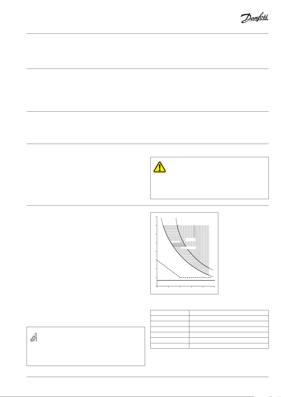
80
75
70
Severe
Painful
Light
temperature
sensation
Scalding
Effects of Domestic Water
Temperatures on Skin
Surfaces. Source: Dr. J.P.
Bull, Industrial Injuries
65
60
55
50
45
and Burns Unit, Medical
0.1 101 100 1000 10000
Research Council
The following reference values of the hazard potential must be
observed:
Up to 38°C Safe temperature for bathing
39 – 45°C Pain sensation after 10 seconds or longer
46 – 48°C Pain sensation 2 – 6 s
49 – 54°C Potential scalding
55 – 59°C Risk of scalding, briefly
60°C and above Scalding hazard, immediate
70°C and above Extreme danger
Source:
Dr. Gabriele Elsäßer, Landesgesundheitsamt Brandenburg
Dr. J.P. Bull, Birmingham Accident Hospital
VI.MP.J3.02
© Danfoss | 2019.08 | 25
Page 26

ThermoDual FLS
10.0 Maintenance
10.1 Safety instructions
The annex contains an overview of the most important technical
regulations. For instructions on maintenance of the system,
see in particular DIN 1988, EN 806, VDI 2895 and VDI 6023. It is
recommended to engage a local installation company for regular
maintenance. Section 10.2 summarizes the most important
measures for specific components and modules. Attached you will
also find the appropriate maintenance and operating instructions
for individual components, which must be observed.
WARNING!
Work on the device must always be carried out by qualified and
suitably trained personnel. Always wear the following personal
protective equipment when using the device:
– Closely fitting clothing (no wide sleeves, rings, etc.)
– Safety glasses to protect the eyes from flying parts and liquids
– Safety shoes for protection against heavy falling parts and
slipping on slippery surfaces
WARNING!
Electrical hazard. Work on electrical equipment may only be carried
out by electricians in compliance with safety regulations.
Before starting work, switch off the electrical supply and secure it
against being switched on again.
Maintenance schedule (recommendations)
Interval Maintenance tasks Remarks
Inspection of all connections If necessary, retighten and/or replace gaskets
Every 2 months
Additionally every
6 months
Additionally every
12 months
Check all parameters for setpoint/actual values
or correctness
Cleaning reversible flow filters See also DIN 1988 / EN 806
General visual inspection of all components
for damages
Functional test of the safety valve See also DIN 1988 / EN 806
Functional test of electrical and electronic
components, switches, etc.
Cleaning of filters or strainers See also DIN 1988 / EN 806
Test of electrical
safety devices
Functional check of all components for function
and operability
Check the external condition Discoloration (corrosion), thermal insulation
Check heat exchanger If soiled, where necessary
Cleaning the tanks/storage tanks See also section 10.2
Check the meters including calibration period
Check the display devices pressure gauges, thermometers
Check expansion vessels Prepressure, load pressure, tightness of membrane
If exceeded: restore parameters to intended values
Functional check where there is visible damage
and replacement where necessary
Manual switch on/off or opening and closing
of actuators
Temperature monitor and/or limiter
e.g. opening and closing shut-off valves
cleaning/descaling (see section 10.2)
26 | © Danfoss | 2019.08
VI.MP.J3.02
Page 27

ThermoDual FLS
10.2 Maintenance tasks
The following are essential tasks that should be performed
during maintenance. Additional information is included in the
manufacturer’s instructions included in the appendix.
The compilation does not claim to be complete. It is important in
every case to observe the legal and relevant technical regulations
as well as the requirements of local conditions and regulations (for
example TCR/”Technical requirements for connecting to network”,
regulations of the utility company, etc.)
Valves:
In general, the valves used are maintenance-free. As part of
maintenance work, functionality should be checked with regard to
ease of movement of hand wheels or levers by opening and closing.
This prevents the accumulation of dirt and limescale deposits on
balls, plates and valve seats.
Heat exchanger:
Heat exchangers in particular are subject to calcification in case of
prolonged operation due to the relatively high temperatures on the
plates or tubes. As part of the aforementioned maintenance tasks,
these devices should be cleaned in case of performance degradation.
Brazed plate heat exchangers can be flushed. With relatively thick
deposits, weak inhibited acid solutions (e.g. 5% formic, acetic or
phosphoric acid) can be used for this. The drawings show this
arrangement:
Flushing and cleaning brazed plate heat exchangers
Tank:
Please refer to separate enclosed documents for details.
10.3 Actions after maintenance tasks
After the maintenance tasks and before switching on the device:
– Check that all previously loosened bolted joints are tight.
– Check that all previously removed guards, covers and tank lids are
properly reinstalled.
– Make sure that all tools, materials and other equipment have been
removed from the work area.
– Clean the work area and remove any leaked substances such as
liquids, processing material or similar.
– Make sure that all safety devices and the system are working
properly again.
Pipes:
The pipes used are made of high-grade stainless steel. If soiled, these
can be treated the same way as tanks. For this you will find instructions
in the operating instructions for stainless steel storage tanks.
VI.MP.J3.02
© Danfoss | 2019.08 | 27
Page 28
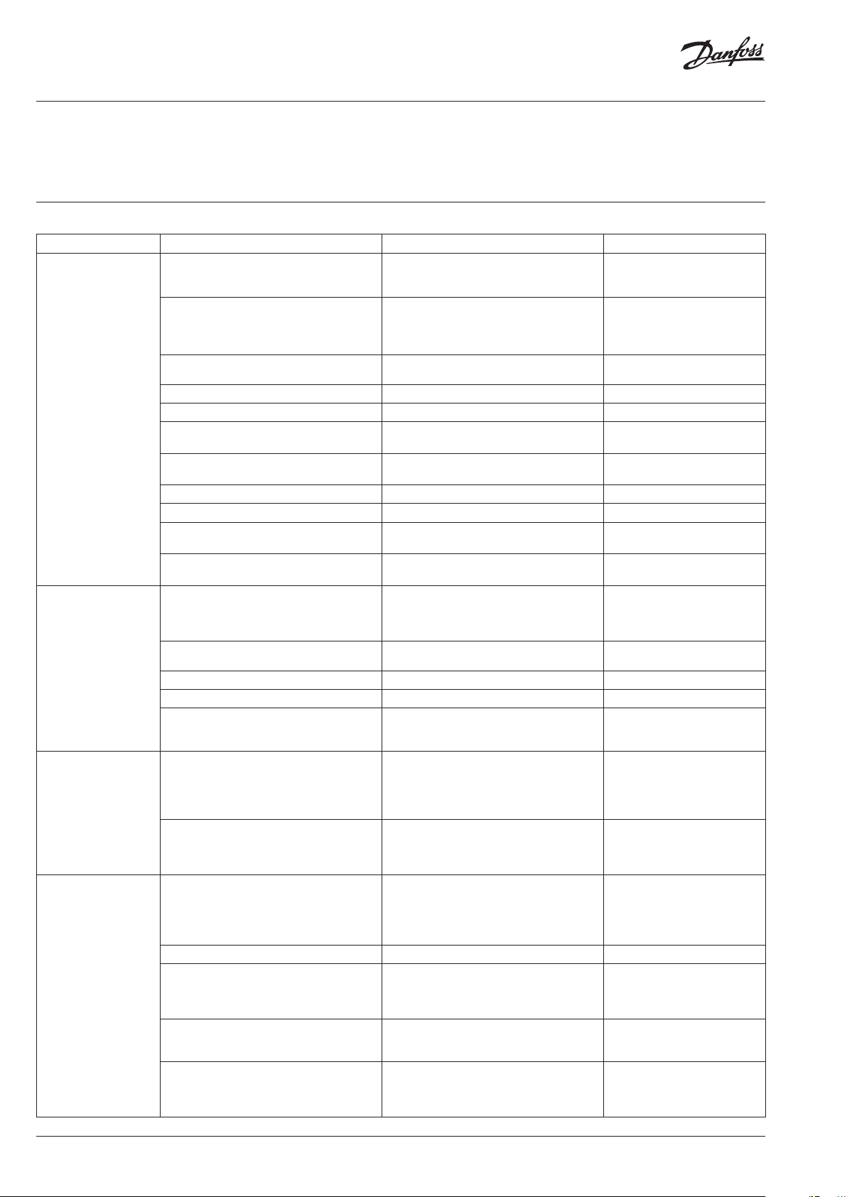
ThermoDual FLS
11.0 Faults
Faults in electrical equipment and in components of mechanical,
pneumatic and hydraulic systems may only be rectified by suitably
trained specialists in these areas. If faults cannot be remedied with
11.1 Malfunctions
Fault Possible cause Remedy Remark
Domestic water
temperature too low
Domestic
water hygiene
endangered.
Domestic water
temperature too high
Risk of scalding.
Domestic water
temperature
fluctuates or
not constant
Risk of scalding.
Leakage of media
Risk of scalding.
No power supply – Turn on the main switch
No water supply
– No cold water pressure
– Primary differential pressure too low
– Not enough hot water
Wrong controller setting(s) Correct settings Operating instructions
Closed shut-off valve(s) Open valves
Defective sensor Replace sensor
Defective charge pump (LPU) or charge
pump not switched on
Defective heating (supply) pump (HPU)
or heating pump not switched on
Defective control valve Clean/free up, exchange if necessary
Defective actuator or thermostat Replace actuator/thermostat
System dimensioned incorrectly – Check dimensioning
System is overdrawn – Check dimensioning
– No power supply
– Electric actuator disconnected
Wrong controller setting(s) Correct settings Operating instructions
Defective sensor Replace sensor
Defective control valve Clean/free up or replace valve Valve stuck
Defective actuator or thermostat Replace actuator/thermostat Actuator in position “OPEN”
Wrong controller setting(s) Correct settings
Fluctuating heating water supply
– Fluctuating primary differential
pressure
– Fluctuating heating water flow
Leaky connections (flange/
screw connections)
Leakage of weld seams Switch off the system Contact customer service
Leakage of valves or fittings
(housing/screw connections)
– Leakage of bolted heat exchangers
– Soiling/calcification
– Pressure surges
– Leakage of brazed or welded
heat exchangers
– Soiling/calcification
– Pressure surges
the measures described below, inform the manufacturer or a service
partner authorized by the manufacturer.
– Check the supply line
– Check circuit br eaker or fuse and contactor
Operating conditions
– Pressure
– Flow rate
– Establish/secure differential pressure
Switch on/replace
Switch on/replace
– Expand/enlarge system
– Expand/enlarge system
– Take the system out of service
– Restore power supply
– If necessary, operate in manual
emergency mode
– Controller gain setting
– Reset time
– Valve operating time / pump
parameters
Operating conditions
– Pressure
– Flow rate
– Establish/secure differential pressure
Switch off the system
– Check operating parameters
for correctness (see label)
– Check connections, retighten
if necessary or replace gaskets
– Check valves for the correct fitting
or installation
– Retighten packing glands or replace
parts
– Retighten bolts
– Open and clean
– Replace gaskets
Change device Operating instructions
Heat or media provider
for controller
Contact our specialist
advisers
Contact our specialist
advisers
for controller
or thermostat/capillary tube
defective
Operating instructions for
controller
Heat or media provider
Operating instructions
Contact manufacturer or
customer service if necessary
Operating instructions
Contact manufacturer or
customer service
Contact manufacturer or
customer service
28 | © Danfoss | 2019.08
VI.MP.J3.02
Page 29

ThermoDual FLS
11.2 What to do when faults occur
The following generally applies:
1. In case of faults that pose an immediate danger to persons,
property and/or operational safety, stop the system immediately
with the emergency stop button.
2. In case of faults which do not pose such risks, switch off the system
via the system controller, disconnect power to the device, and
secure it against reconnection.
3. Immediately inform the responsible person on site about the
problem.
4. Have authorized specialist personnel determine the nature
and extent of the fault, determine the cause, and have the fault
rectified.
12.0 Spare parts
Only use original spare parts from the manufacturer.
If non-approved spare parts are used, all warranty, service, damage
and liability claims against the manufacturer or its agents, dealers
and representatives are forfeited.
When ordering spare parts, please indicate:
– Device type
– ID/production number
– Part number / item number (see parts list / wiring diagram)
– Quantity
– Designation
– Desired shipping method (post, freight, sea, air, express)
– Shipping address
– If necessary, a sketch or photo with comments
WARNING!
Improper troubleshooting can result in serious personal injury and/
or property damage. It may therefore only be carried out by trained
and authorized specialist personnel.
CAUTION!
Incorrect or faulty replacement parts and components from thirdparty manufacturers can lead to severe damage, malfunction or
total failure of the device.
Spare parts orders without above-mentioned information cannot be
processed. If you do not specify the shipping method, shipping is at the
discretion of the supplier. Inform the manufacturer comprehensively
about parts usage so that an equivalent replacement can be offered.
VI.MP.J3.02
© Danfoss | 2019.08 | 29
Page 30

ThermoDual FLS
INDEX
B
Buffer tank charging ..................................................................................... 21
C
Circuit diagram ......................................................................................... 11, 29
Commissioning/recommissioning ................... 4, 10, 14, 18, 22, 23, 25
Construction ....................................................................................... 12, 14, 31
Control, controller ........................................................ 11, 12, 19, 22, 23, 25
Copyright ............................................................................................................ 4
D
De-energized ................................................................................. 8, 10, 14, 23
Default settings ....................................................................................... 23, 24
Dismantling ............................................................................................... 3, 4, 5
Disposal ................................................................................................ 3, 4, 5, 17
Disturbances ........................................................................................ 4, 28, 29
E
Electrical connection .................................................................................... 18
Emergency stop (switch) ................................................................ 7, 8, 9, 29
F
Flow-through system ................................................................................... 12
Function ................................................................... 3, 4, 9, 12, 26, 27, 28, 29
G
Gasket ................................................................................................................. 15
General information ............................................................................. 3, 6, 14
H
Heat supply ............................................................................................... 18, 22
Hygiene .............................................................................................................. 25
I
Installation/company .................................................. 3, 6, 7, 14, 18, 22, 26
Installation preparation ............................................................................... 18
Instantaneous water heater ....................................................................... 12
Intended use ...................................................................................................6, 7
L
Liability ................................................................................................................. 4
P
Packing ........................................................................................................ 16, 17
Parameter ............................................................................... 10, 11, 22, 26, 28
Primary side ........................................................................................ 18, 22, 23
Protective equipment ......................................................................... 7, 8, 26
Protective gloves .......................................................................................... 7, 8
Protective helmet ............................................................................................ 7
Q
Qualified personnel ........................................... 4, 9, 10, 14, 18, 22, 28, 29
R
Recommissioning ................................................................................... 22, 25
Responsibility of the operator .................................................................... 6
Risks ........................................................................................ 3, 6, 7, 8, 9, 10, 29
S
Safety ............................................ 3, 6, 7, 8, 9, 14, 16, 18, 22, 25, 26, 27, 29
Safety goggles ............................................................................................ 7, 26
Safety shoes ................................................................................................. 7, 26
Safety Valve .................................................................................. 10, 11, 21, 26
Secondary side ......................................................................................... 18, 22
Sensor ............................................................................................. 11, 12, 21, 28
Servicing ................................................................... 3, 6, 8, 18, 21, 22, 26, 27
Spare parts ................................................................................................... 4, 29
Storage ........................................................................................................ 12, 26
Storage ........................................................................................................ 16, 17
Strainer ................................................................................................. 10, 22, 26
Switching off ....................................................................... 4, 8,23, 25, 26, 29
T
Technical data ................................................................................................. 11
Thermal disinfection ..................................................................................... 25
Thermal layering ............................................................................................ 21
Transport (-) .................................................................................... 8, 16, 17, 21
Transport inspection ..................................................................................... 17
Turning on/turning back on ..................... 4, 8, 10, 23, 25, 26, 27, 28, 29
W
Warranty ................................................................................................ 4, 22, 29
M
Maintenance tasks .................................................................... 21, 22, 26, 27
Malfunction or taking out of service ...................................................... 23
Malfunctions .................................................................................................... 28
O
Occupational health and safety ........................................................ 3, 6, 7
Operating instructions ................................................................... 3, 4, 6, 10
Operating personnel .................................................................................. 3, 9
Operation or operating instructions .3, 6, 9, 10, 21, 22, 23, 25, 26, 28
Operator ............................................................................................... 6, 7, 9, 10
Other applicable documents ....................................................................... 3
30 | © Danfoss | 2019.08
VI.MP.J3.02
Page 31

ThermoDual FLS
Annex
Layout / Part locations
Heating pump
(only for 3-way-vale-
or pump control)
Flow sensor
Circulation pump
Safety valve
Air-vent
Balancing valve
(Taco-Setter)
Heat exchanger
(brazed)
Electronic
Controller
Drain
(Domestic water)
Drain
(Heating)
Domestic
water (cold)
Circulation
(Inlet)
Domestic hot water
(hot/network)
Heating supplyHeating return
Control valve
(only for 2-way-valve.
or 3-way-valve control)
VI.MP.J3.02
© Danfoss | 2019.08 | 31
Page 32

Durchflusssensor für flüssige Medien Typ 210
Flowsensor for Liquids type 210
Débitmètre pour liquides type 210
min. 5xDN
für nicht ideale Krümmungen
for alternative elbows
pour des coudes non idéaux
min. 0.5xDN
pour des coudes idéaux à 90À
avec au mini R 1.8xDN
min. 0.5xDN
for recommended 90À elbow
with min. R 1.8xDN
min. 0.5xDN
für ideale 90À Krümmungen
mit min. R 1.8xDN
On Request
(No air bubble)
according EN 61326-2-3
min. 1xDN
min. R 1.8xDN
ThermoDual FLS
HUBA Control flow sensor DS 210
32 | © Danfoss | 2019.08
VI.MP.J3.02
Page 33
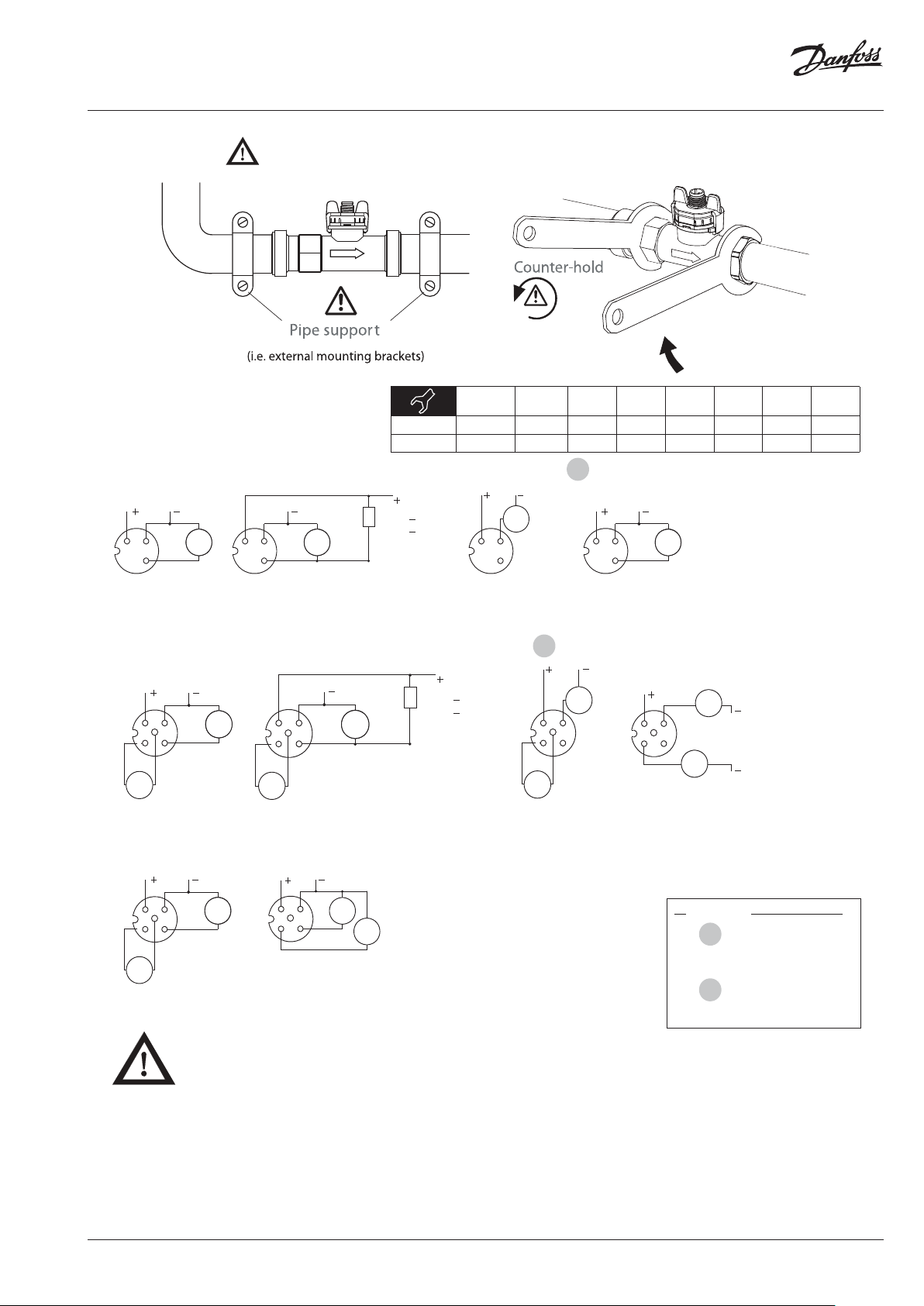
DN6/8/10
G ½
DN6/8/10
G ¾
DN15
G ¾
DN15
G1
DN20
G1
DN20
G1 ¼
DN25
G1 ¼
DN25
G1 ½
M
min
[Nm] 1 1 1 2 2 2.5 2.5 2.5
M
max
[Nm] 12 12 12 12 12 15 15 15
Montage
Speisung durch SELV- oder Klasse 2-Spannungsversorgung.
Qualifiziertes Personal
Geräte dieser Sensorserie dürfen nur von qualifiziertem Personal und ausschliesslich entsprechend der technischen Daten verwendet werden. Qualifiziertes Personal sind Personen, die mit der Aufstellung, Montage,
Inbetriebnahme und Betrieb dieses Gerätes vertraut sind und die über eine ihrer Tätigkeit entsprechende Qualifiaktion verfügen.
Mounting
Supply from SELV or class 2 source.
Qualified staff
The devices may only be installed, connected, set-up and operated by qualified staff and in compliance with the technical specifications. Qualified staff is defined as persons, who are familiar with set-up, mounting,
start-up and operation of this device and who possess a recognized degree or certificate of appropriate professional training.
Montage
Alimentation uniquement par SELV ou issu dÂune source de class 2.
Personnel qualifié
Les appareils de cette série de transmetteurs ne doivent être utilisés que par du personnel qualifié et uniquement suivant les données techniques. Par personnel qualifié on entend les personnes qui connaissent
bien lÂinstallation, le montage, la mise en service et le fonctionnement de cet appareil, et qui disposent dÊune qualification appropriée.
Stressless mounting
M12x1 ohne Temperaturmessung / M12x1 without temperature output / M12x1 sans sortie température
M12x1 mit Temperaturmessung / M12x1 with temperature output / M12x1 avec sortie température
Pin Farbe / colour / couleur
1 braun / brown / brun
3 blau / blue / bleu
4 schwarz / black / noir
1 braun / brown / brun
2 weiss / white / blanc
3 blau / blue / bleu
4 schwarz / black / noir
5 grau / gray / gris
1
2
1
2
Stromausgang
Current output
Sortie courant
3
4
1
A
GND
IN
Spannungsausgang
Voltage output
Sortie tension
OUT
3
4
1
V
OUT
Q
GND
IN
Frequenzausgang ungefiltert
Frequency output unfiltered
Sortie fréquence non filtrée
3
4
1
GND
IN
OUT
Hz
3
4
1
GND
OUT
Hz
IN
Pullup < 10kΩ
> 1kΩ
Frequenzausgang gefiltert, Impulsausgang
Frequency output filtered, pulse output
Sortie fréquence filtrée, sortie à impulsions
Spannungsausgang mit PT1000
Voltage output with PT1000
Sortie tension avec PT1000
OUT
3
4
1
5
T1T2
Ω
2
V
OUT
Q
GND
IN
Spannungsausgang mit 0 ...10 V
Voltage output with 0 ...10 V
Sortie tension avec 0 ...10 V
3
4
1
5
OUT
Q
2
V
V
OUT
T
GND
IN
IN
Stromausgang mit PT1000
Current output with PT1000
Sortie courant avec PT1000
3
4
1
A
5
T1T2
Ω
2
GND
IN
Frequenzausgang mit PT1000
Frequency output with PT1000
Sortie fréquence avec PT1000
T1T2
3
4
1
5
Ω
2
GND
IN
Hz
3
4
1
5
OUT
Q
2
A
OUT
T
GND
IN
Stromausgang mit 4 ... 20 mA
Current output with 4 ... 20 mA
Sortie courant avec 4 ... 20 mA
A
GND
3
4
1
GND
OUT
Hz
Pullup < 10kΩ
> 1kΩ
Frequenzausgang gefiltert, Impulsausgang
Frequency output filtered, pulse output
Sortie fréquence filtrée, sortie à impulsions
5
2
Ω
ThermoDual FLS
VI.MP.J3.02
© Danfoss | 2019.08 | 33
Page 34
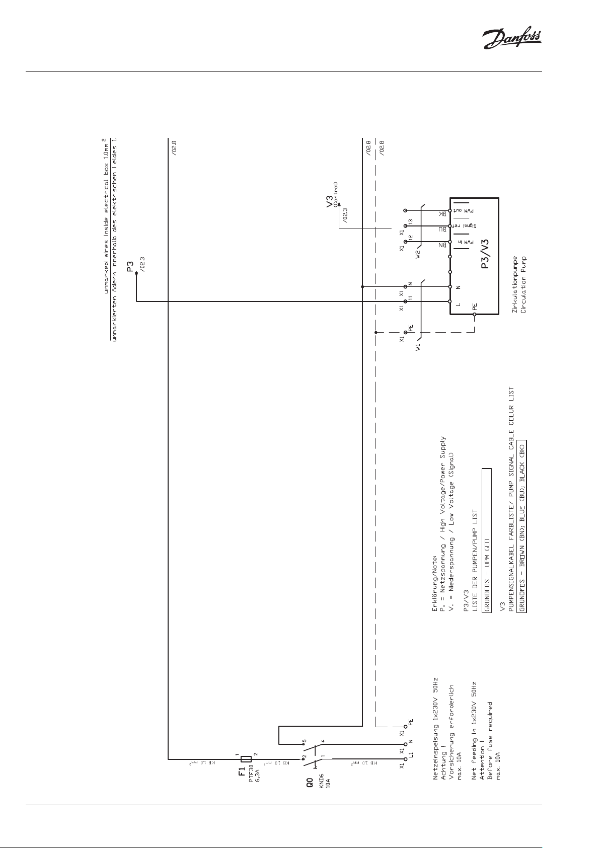
ThermoDual FLS
Wiring diagram
power supply and pump connections
Variant: 2-way-valve control
34 | © Danfoss | 2019.08
VI.MP.J3.02
Page 35
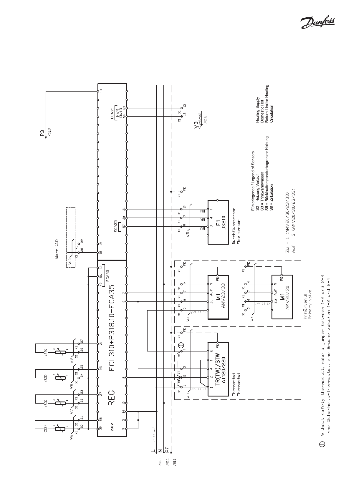
ThermoDual FLS
Wiring diagram
Controller drive and
sensor terminal assignments
Variant: 2-way-valve control
VI.MP.J3.02
© Danfoss | 2019.08 | 35
Page 36
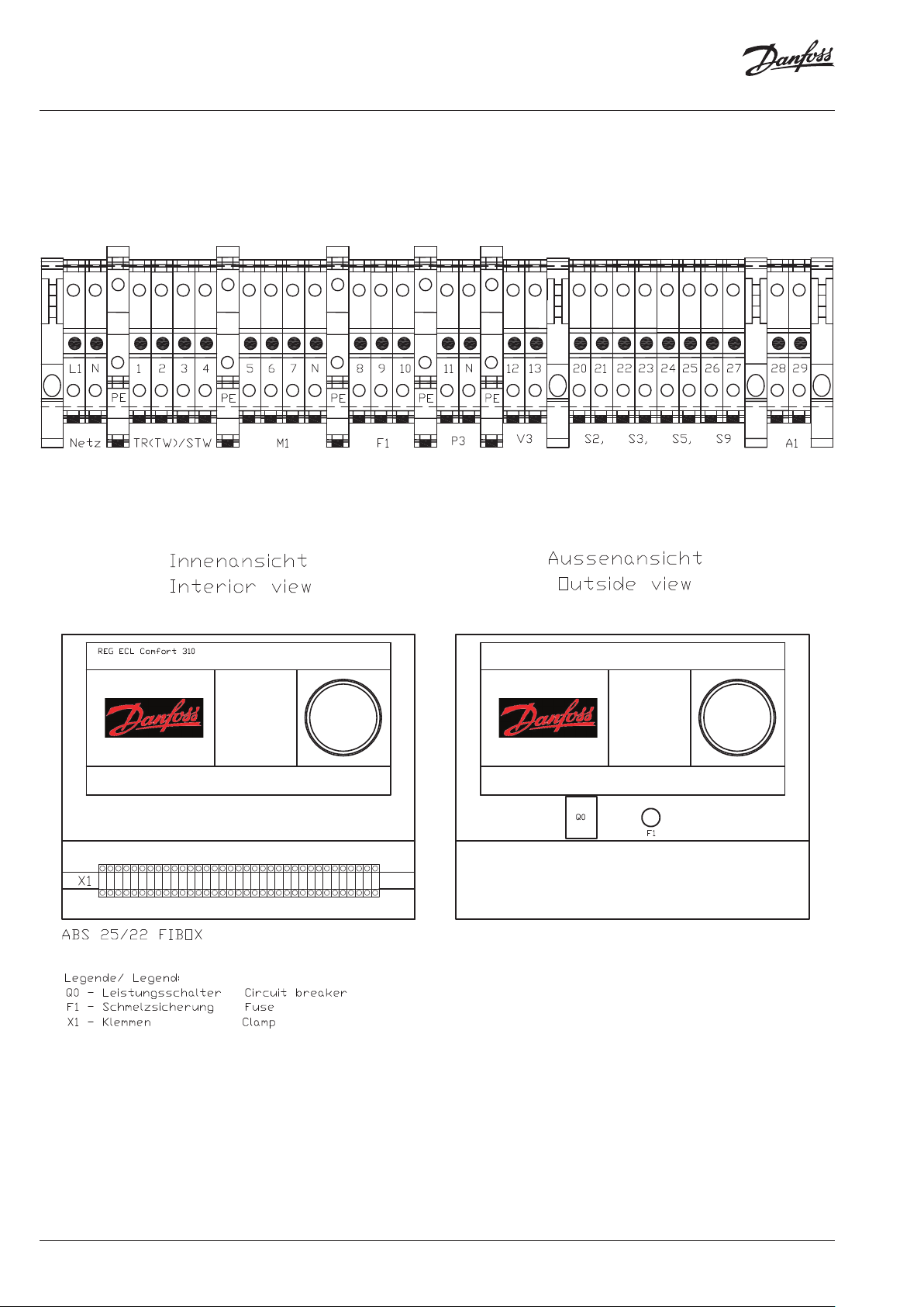
ThermoDual FLS
Wiring diagram
Terminal plan X1
Variant: 2-way-valve control
36 | © Danfoss | 2019.08
VI.MP.J3.02
Page 37
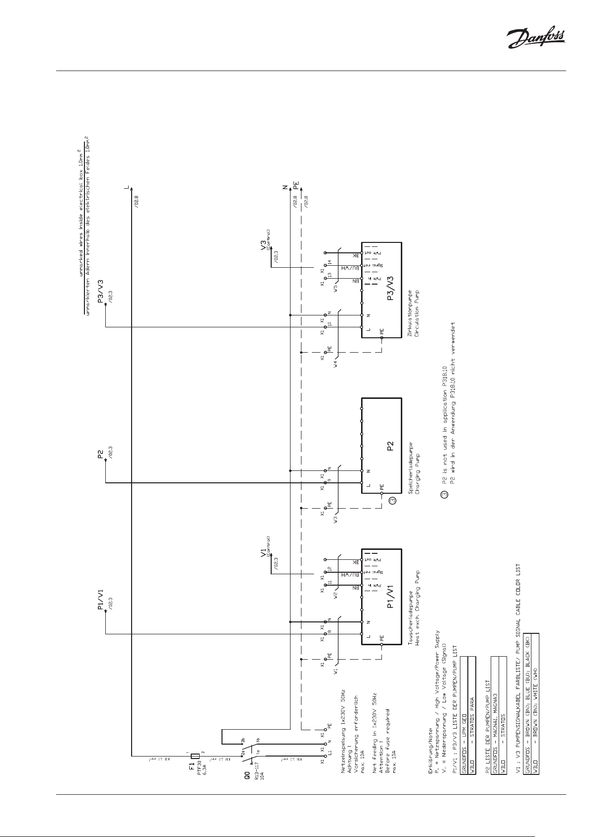
ThermoDual FLS
Wiring diagram
power supply and pump connections
Variant: 3-way-valve and pump control
VI.MP.J3.02
© Danfoss | 2019.08 | 37
Page 38
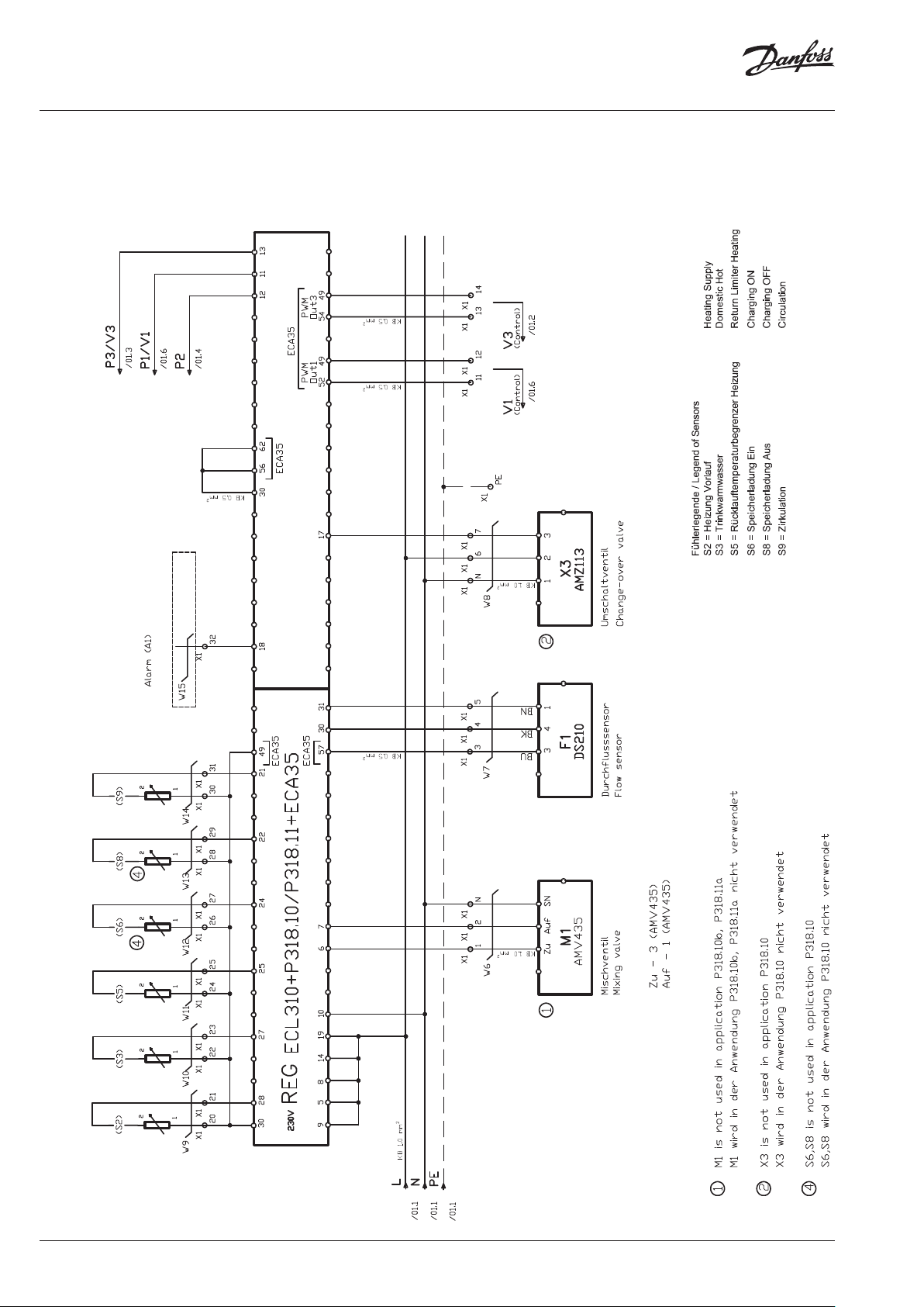
ThermoDual FLS
Wiring diagram
Controller drive and sensor terminal assignments
Variant: 3-way-valve and pump control
38 | © Danfoss | 2019.08
VI.MP.J3.02
Page 39

ThermoDual FLS
Wiring diagram
Terminal plan X1
Variant: 3-way-valve and pump control
VI.MP.J3.02
© Danfoss | 2019.08 | 39
Page 40
500B0577A04 1
st
Issue 2015
-06
Page 1 of 2
Danfoss A/S
Telephone: +45 74 88 2222
ThermoDual FLS
Declares under our sole responsibility that the
Product(s) Heavy Duty Stations for Domestic Hot Water
Type(s)
Covered by this declaration is in conformity with the following directive(s), standard(s) or other normative
document(s), provided that the product is used in accordance with our instructions.
MD – Machinery Directive (2006/42/EC)
EN ISO 12100:2011 Safety of Machinery – General principles for design – Risk assessment and risk reduction
EN 60204-1:2016, Safety of machinery – Electrical equipment of machines – Part 1: General requirements
EN 60730-1:2016, Automatic electrical controls for household and similar use – Part 1: General
requirements
EN 60730-2-9:2011, Automatic electrical controls for household and similar use - Part 2-9: Particular
requirements for temperature sensing controls.
ID No: VJLZE25B
EU DECLARATION OF CONFORMITY
TD-FLS COMBI
TD-FLS
TD-CM
TD-CMG
TD-CIRC
TD-S
LM-S
TD-GS
MH
TC-C
TC-DL
Danfoss A/S
Danfoss Heating Segment
ThermoDual® FLS Combi Instantaneous Domestic Hot Water
Heater
ThermoDual® FLS Instantaneous Domestic Hot Water Heater
ThermoDual® CM Storage Charging System, Brazed
ThermoDual® CM Storage Charging System, Gasketed
ThermoDual® CM Circulation System, Brazed
ThermoDual® TD-S, LM-S, TD-GS Storage Charging System with
tank, Brazed + Gasketed
Multiheat 2-Step-Storage Charging System, Brazed
ThermoClean® Combi Antilegionella System, Brazed
ThermoClean® DL Antilegionella System, Brazed
DK-6430 Nordborg
Denmark
CVR nr.: 20 16 57 15
Fax:+45 7449 0949
40 | © Danfoss | 2019.08
VI.MP.J3.02
Page 41

23.06
.2017 Signature
2
3.06
.2017 Signature
ThermoDual FLS
EMC – Electromagnetic Compatibility Directive (2014/30/EU)
EN 61000-6-1:2007, Electromagnetic compatibility (EMC) – Part 6-1: Generic standards – Immunity for
residential, commercial and light-industrial environments
EN 61000-6-2:2005, Electromagnetic compatibility (EMC) – Part 6-2: Generic standards – Immunity for
industrial environments
EN 61000-6-3:2007, Electromagnetic compatibility (EMC) – Part 6-3: Generic standards – Emission
standard for residential, commercial and light-industrial environments
EN 61000-6-4:2007, Electromagnetic compatibility (EMC) – Part 6-4: Generic standards – Emission
standard for industrial environments
Products marked as PED Category I, II, III covered by this declaration, are also in conformity with the
following directive(s), standard(s) or other normative document(s), provided that the product is used in
accordance with our instructions.
PED – Pressure Equipment Directive (2014/68/EU)
EN 13480-1:2012, Metallic industrial piping – Part 1: General
EN 13480-4:2012, Metallic industrial piping – Part 4: Fabrication and installation
EN 13480-5:2012, Metallic industrial piping – Part 5: Inspection and testing
Products marked as PED Category I covered by this declaration, have been evaluated by Conformity
Assessment Procedure according to Module A: Internal control of inspection.
Products marked with PED Category II, III covered by this declaration, have been evaluated by
Notified Body – 0041
Bureau Veritas UK, Parklands, Wilmslow Road
Didsbury, Manchester,
M20 2RE – United Kingdom
According to Module H1: Full quality assurance plus design examination.
The following certificate has been issued:
CE-0041-PED-H1-DAN-001-15-DNK-rev-A
Products are marked with 0041
VI.MP.J3.02
Date Issued by Date Approved by
Name: Firan Mihai Lucian
Title: R&D Manager
Danfoss only vouches for the correctness of the English version of this declaration. In the event of the declaration being translated into any other
language, the translator concerned shall be liable for the correctness of the translation
ID No: VJLZE25B
500B0577A04 1
st
Issue 2015-06
Page 2of 2
Name: Marcin Rewucki
Title: Quality Director
© Danfoss | 2019.08 | 41
Page 42

500B0577A04
1st
Issue 201
5-06
Page 1 of 2
Danfoss A/S
Telephone: +45 74 88 2222
ThermoDual FLS
erklärt in alleiniger Verantwortung, dass das (die)
Produkt(e) Trinkwassererwärmungssystem(e)
Typ(e)
Voraussetzung ist, dass die Produkte bestimmungsgemäß entsprechend der Betriebsanleitung eingesetzt
werden und keine Veränderungen an den Produkten durch Dritte vorgenommen wurden.
MD - Maschinenrichtlinie (2006/42/EG)
EN ISO 12100: 2011 Sicherheit von Maschinen - Allgemeine Gestaltungsleitsätze - Risikobeurteilung
und Risikominderung
EN 60204-1: 2016 Sicherheit von Maschinen - Elektrische Ausrüstung von Maschinen - Teil 1: Allgemeine
Anforderungen
EN 60730-1: 2016 Automatische elektrische Regel- und Steuergeräte - Teil 1: Allgemeine Anforderungen
EN 60730-2-9: 2011 Automatische elektrische Regel- und Steuergeräte für den Hausgebrauch und ähnliche
Anwendungen - Teil 2-9: Besondere Anforderungen an temperaturabhängige Steuerungen
DK-6430 Nordborg
Denmark
CVR nr.: 20 16 57 15
Fax:+45 7449 0949
EU Konformitätserklärung
Danfoss A/S
Danfoss Heating Segment
TD-FLS COMBI ThermoDual® FLS Combi Durchflußwassererwärmer
TD-FLS ThermoDual® FLS Durchflußwassererwärmer
TD-CM ThermoDual® CM Speicherlademodul, gelötet
TD-CMG ThermoDual® CM Speicherladesystem, geschraubt
TD-CIRC ThermoDual® CIR Zirkulationsmodul, gelötet
TD-S,
LM-S,
TD-GS
MH Multiheat 2-Schritt-Speicherlademodul, gelötet
TC-C ThermoClean® Combi Antilegionellen System, gelötet
TC-DL ThermoClean® DL Antilegionellen System, gelötet
ThermoDual® TD-S, LM-S, TD-GS
Speicherladesystem incl. Speicher, Gelötete +
Gedichtete Wärmeübertrager-Ausführung
42 | © Danfoss | 2019.08
ID No: VJLZE25B
VI.MP.J3.02
Page 43

23.06
.2017 Signature
23.06
.2017 Signature
ThermoDual FLS
EMV - Elektromagnetische Verträglichkeit (2014/30/EU)
EN 61000-6-1: 2007 Elektromagnetische Verträglichkeit (EMV) - Teil 6-1: Fachgrundnormen - Störfestigkeit
für Wohnbereich , Geschäfts- und Gewerbebereich
EN 61000-6-2: 2005 Elektromagnetische Verträglichkeit (EMV) - Teil 6-2: Fachgrundnormen - Störfestigkeit
für Industriebereiche
EN 61000-6-3: 2007 Elektromagnetische Verträglichkeit (EMV) - Teil 6-3: Fachgrundnormen Störaussendung für Wohn-, Geschäfts- und Gewerbebereich
EN 61000-6-4: 2007 Elektromagnetische Verträglichkeit (EMV) - Teil 6-4: Fachgrundnormen Störaussendung für Industriebereich
Produkte, die als PED-Kategorie I, II, III gekennzeichnet sind und unter diese Erklärung fallen, stimmen
auch mit den folgenden Direktiven, Standards oder anderen normativen Standards überein, sofern die
Produkte gemäß unseren Anweisungen verwendet werden.
PED - Druckgeräterichtlinie (2014/68/EU)
EN 13480-1:2012 Metallische industrielle Rohrleitungen - Teil 1: Allgemeines
EN 13480-4:2012 Metallische industrielle Rohrleitungen - Teil 4: Fertigung und Verlegung
EN 13480-5:2012 Metallische industrielle Rohrleitungen - Teil 5: Prüfung
Produkte, die als PED-Kategorie I gekennzeichnet sind und unter diese Erklärung fallen, wurden nach dem
Konformitätsbewertungsverfahren gemäß Modul A: „Interne Fertigungskontrolle“ geprüft und bewertet.
Produkte, die als PED-Kategorie II, III gekennzeichnet sind und unter diese Erklärung fallen, wurden nach
dem Konformitätsbewertungsverfahren gemäß Modul H1: „Vollständige Qualitätssicherung plus
Designprüfung“ geprüft und bewertet. Die Prüfung erfolgte durch:
Benannte Stelle - 0041
Bureau Veritas UK, Parklands, Wilmslow Road
Didsbury, Manchester,
M20 2RE – United Kingdom
Ausgestelltes Zertifikat:
CE-0041-PED-H1-DAN-001-15-DNK-rev-A
Produkte sind gekennzeichnet mit 0041
VI.MP.J3.02
Date Issued by Date Approved by
Name: Firan Mihai Lucian
Title: R&D Manager
Danfoss only vouches for the correctness of the English version of this declaration. In the event of the declaration being translated into any other
language, the translator concerned shall be liable for the correctness of the translation
ID No: VJLZE25B
500B0577A04 1
st
Issue 2015-06 Page 2of 2
Name: Marcin Rewucki
Title: Quality Director
© Danfoss | 2019.08 | 43
Page 44
500B0577A02
1st Issue 2015
-06
Page 1 of 2
Danfoss A/S
Teleph
ThermoDual FLS
Declares under our sole responsibility that the
Product(s) Heavy Duty Stations for Domestic Hot Water
Type(s)
Covered by this declaration is in conformity with the following directive(s), standard(s) or other normative
document(s), provided that the product is used in accordance with our instructions.
Council Directive 98/83/EC of 3 November 1998 on the quality of water intended for human
consumption
EN 806-1:2000 Specification for installations inside buildings conveying water for human consumption –
Part 1: General
EN 806-2:2005 Specification for installations inside buildings conveying water for human consumption –
Part 2: Design
EN 806-3:2006 Specification for installations inside buildings conveying water for human consumption –
Part 3: Pipe sizing – Simplified method
ID No: VJLZC25B
DK-6430 Nordborg
Denmark
CVR nr.: 20 16 57 15
one: +45 7488 22 22
Fax: +45 7449 0949
MANUFACTURER’S DECLARATION
Danfoss A/S
Danfoss Heating Segment
TD-FLS COMBI ThermoDual® FLS Combi Instantaneous Domestic Hot Water
Heater
TD-FLS ThermoDual® FLS Instantaneous Domestic Hot Water Heater
TD-CM ThermoDual® CM Storage Charging System, Brazed
TD-CMG ThermoDual® CM Storage Charging System, Gasketed
TD-CIRC ThermoDual® CM Circulation System, Brazed
TD-S
LM-S
TD-GS
MH Multiheat 2-Step-Storage Charging System, Brazed
TC-C ThermoClean® Combi Antilegionella System, Brazed
TC-DL ThermoClean® DL Antilegionella System, Brazed
ThermoDual® TD-S, LM-S, TD-GS Storage Charging System
with tank, Brazed + Gasketed
44 | © Danfoss | 2019.08
VI.MP.J3.02
Page 45

23.06
.2017 Signature
23.06
.2017 Signature
ThermoDual FLS
National norms and legislations Germany and Austria:
DIN 4747-1:2009 Heating plants for district heating - Part 1: Safety requirements for domestic substations,
stations and domestic systems to be connected to hot-water district heating networks, Corrigendum to DIN
4747-1:2003-11
DIN 4753-3:2011 Water heaters, water heating installations and storage water heaters for drinking water Part 3: Corrosion protection on the water side by enamelling and cathodic protection - Requirements
and testing
DIN 1988-600:2010 Codes of practice for drinking water installations - Part 600: Drinking water installations
in connection with firefighting and fire protection installations;
DVGW code of practice, DWGW working sheet W551
AGFW Guide FW527
DIN EN 12828:2014 Heating systems in buildings - Design for water-based heating systems; German version
EN 12828:2012+A1:2014
Ö-Norm B 5019 Hygienic aspects of the planning, construction, operation, surveillance and rehabilitation
of central heating installations for drinking water.
VI.MP.J3.02
Date Issued by Date Approved by
Name: Firan Mihai Lucian
Title: R&D Manager
Danfoss only vouches for the correctness of the English version of this declaration. In the event of the declaration being translated into any other
language, the translator concerned shall be liable for the correctness of the translation
ID No: VJLZC25B
500B0577A02 1st Issue 2015-06 Page
Name: Marcin Rewucki
Title: Quality Director
2of 2
© Danfoss | 2019.08 | 45
Page 46

500B0577A02
1st Issue 201
5-06
Page 1 of 2
Danfoss A/S
Teleph
ThermoDual FLS
erklärt in alleiniger Verantwortung, dass das(die)
Produkt(e) Trinkwassererwärmungssystem(e)
Typ(e)
Voraussetzung ist, dass die Produkte bestimmungsgemäß entsprechend der Betriebsanleitung eingesetzt
werden und keine Veränderungen an den Produkten durch Dritte vorgenommen wurden.
Richtlinie 98/83/EG des Rates vom 3. November 1998 über die Qualität von Wasser für
den menschlichen Gebrauch
EN 806-1:2000 Technische Regeln für Trinkwasser-Installationen - Teil 1: Allgemeines
EN 806-2:2005 Technische Regeln für Trinkwasser-Installationen - Teil 2: Planung
EN 806-3:2006 Technische Regeln für Trinkwasser-Installationen - Teil 3: Berechnung
der Rohrinnendurchmesser - Vereinfachtes Verfahren
DK-6430 Nordborg
Denmark
CVR nr.: 20 16 57 15
one: +45 7488 22 22
Fax: +45 7449 0949
Herstellererklärung
Danfoss A/S
Danfoss Heating Segment
TD-FLS COMBI ThermoDual® FLS Combi Durchflußwassererwärmer
TD-FLS ThermoDual® FLS Durchflußwassererwärmer
TD-CM ThermoDual® CM Speicherlademodul, gelötet
TD-CMG ThermoDual® CM Speicherladesystem, geschraubt
TD-CIRC ThermoDual® CIR Zirkulationsmodul, gelötet
TD-S,
LM-S,
TD-GS
MH Multiheat 2-Schritt-Speicherlademodul, gelötet
TC-C ThermoClean® Combi Antilegionellen System, gelötet
TC-DL ThermoClean® DL Antilegionellen System, gelötet
ThermoDual® TD-S, LM-S, TD-GS Speicherladesystem
incl. Speicher, Gelötete + Gedichtete WärmeübertragerAusführung
46 | © Danfoss | 2019.08
ID No: VJLZC25B
VI.MP.J3.02
Page 47

23
.06
.2017 Signature
23
.06
.2017 Signature
ThermoDual FLS
Nationale Normen und Vorschriften in Deutschland und Österreich:
DIN 4747-1:2009-09 Fernwärmeanlagen - Teil 1: Sicherheitstechnische Ausrüstung von Unterstationen,
Hausstationen und Hausanlagen zum Anschluss an Heizwasser-Fernwärmenetze, Berichtigung zu DIN
4747-1:2003-11
DIN 4753-3:2011-11 Trinkwassererwärmer, Trinkwassererwärmungsanlagen und SpeicherTrinkwassererwärmer - Teil 3: Wasserseitiger Korrosionsschutz durch Emaillierung und kathodischer
Korrosionsschutz - Anforderungen und Prüfung
DIN 1988-600:2010-12 Technische Regeln für Trinkwasser-Installationen - Teil 600: TrinkwasserInstallationen in Verbindung mit Feuerlösch- und Brandschutzanlagen;
Technische Regel des DVGW, DWGW Arbeitsblatt W551
AGFW Richtlinie FW527
DIN EN 12828:2014-07 Heizungsanlagen in Gebäuden - Planung von Warmwasser-Heizungsanlagen;
Deutsche Fassung EN 12828:2012+A1:2014
Ö-Norm B 5019 Hygienerelevante Planung, Ausführung, Betrieb, Überwachung und Sanierung
von zentralen Trinkwasser-Erwärmungsanlagen
VI.MP.J3.02
Date Issued by Date Approved by
Name: Firan Mihai Lucian
Title: R&D Manager
Danfoss only vouches for the correctness of the English version of this declaration. In the event of the declaration being translated into any other
language, the translator concerned shall be liable for the correctness of the translation
ID No: VJLZC25B
500B0577A02 1st Issue 2015-06 Page
Name: Marcin Rewucki
Title: Quality Director
2of 2
© Danfoss | 2019.08 | 47
Page 48
ThermoDual FLS
Field device configuration and hydraulic parameters
(pumps / control valves / heat exchanger)
System and control application
System
Control
Capacity
[kW] Type Application Code Type Typ e [m
140
00 4X1653 XB59M-1-30
Heat
exchanger
Pump, heating side
Heating
pump [P1]
Nominal
flow
3
/h] Type [m3/h] Ty pe [l/min] Type MAX [m3/h] MAX [kPa]
210 004X1654 XB59M-1-30 10,00 60 43
280 004X1655 XB59M-1-36 10,00 80 45
350 004X1656 XB59M-1-50 16,00 100
420 004X1657 XB 59M-1-50 25,00 12 0 30
455 00 4X1658 XB59M-1-70 25,00 13 0 31
140
318.10a
Safety Function
2-Way-Valve w./o.
not relevant VM2
00 4X1659 XB59M-1-30
210 00 4X1660 XB59M-1-30 10,00 60 43
280 004X1661 XB59M-1-36 10,0 0 80 45
350 004X1662 XB59M-1-50 16,00 100
420 00 4X1663 XB59M-1-50 25,00 120 30
455 004X166 4 XB59M-1-70 25,00 130 31
140
210 0 04X1815 XB59M-1-30
280 00 4X1816 XB59M-1-36
350 0 04X1817 XB59M-1-50
420 004X1818 XB59M-1- 60
455 004X1819 X B59M -1-80
140
210 00 4X1809 XB59M-1-30
280 004X1810 XB59M-1-36
350 0 04 X1811 XB59M -1-50
420 0 04X1812 XB59M-1-50
455 004X1813 XB59M -1-70
318.10a
Safety Function
2-Way-Valve incl.
00 4X1814 XB59M-1-30
318.10c
+ Pump
3-Way-Mixing-Valve
00 4X1808 XB59M-1-30
318.10b
Pump Control
not relevant VM2
UPM GEO
25-85
STRATOS PARA
25/1-12
STRATOS PARA
25/1-12
STRATOS PARA
25/1-12
STRATOS PARA
30/1-12
STRATOS PARA
30/1-12
UPM GEO
25-85
STRATOS PARA
25/1-12
STRATOS PARA
25/1-12
STRATOS PARA
25/1-12
STRATOS PARA
30/1-12
STRATOS PARA
30/1-12
2,38
3,78 10,00 60 43
5,12 10,00 80 45
6,25 16,00 100
7,48 25,00 120 32
7,85 25,00 13 0 33
2,38
3,78 60 43
5,12 80 45
6,25 100
7,74 120 30
8,01 130 31
Valve / Actuator
heating side
Valve k
VS
6,30
6,30
6,30
VRG3
not relevant
Actu-
ator
[M1]
AMV
30
AMV
33
AMV
435
DHW Pump, circulation
Nominal
flow
Circulation
pump [P3]
Flow
40
2,40
"UPM GEO
25-85N"
3,40
40
2,40
"UPM GEO
25-85N"
3,40
40
2,40
"UPM GEO
25-85N"
3,40
40
2,40
"UPM GEO
25-85N"
3,40
Residual
pressure
head
43
30
43
30
43
30
43
30
48 | © Danfoss | DHS-SDBT / PL | 2019.08
VI.MP.J3.02
 Loading...