

Page 1
Technical Paper
Flow and Dierence Pressure Optimize Guide
Introduction
Balancing a
heating system
Between 80 and 90 % of all buildings in Northern
Europe have heating systems with little or no
hydronic balancing.
The results are:
• Discomfort due to under- or overheating
• Discomfort due to noise problems
• High energy costs
The purpose of balancing a heating system is to
optimize the ow and get as good a heat consumption as possible.
To achieve this we have to make sure that the
right amount of water is distributed to the
radiators, as well as the pump pressure or setting
of the dierential pressure regulator is correct.
Balancing - installation - performance
1. Exact calculation of the heating output,
or
2. Estimation of the Heating output:
• Get drawings with room sizes in m2 of all ats.
If drawings are not available a laser range
nder can be used for measuring the areas.
• Select the heat loss.
• Calculate the ow.
• Determine preset values for each radiator
valve according to the calculated ow. Find
the selected preset in the Presetting table (see
next page).
• Decide together with the property owner or
caretaker limitations and the current room
temperature. Consider the need for thermostats with remote sensor.
• All radiator valves must be preset.
• Fill with water and bleed the system.
In 2-pipe heating systems a correct dimensioning
and adjustment of the valves is a prerequisition
for achieving optimal energy consumption and
high user comfort.
By spending a few minutes on studying this
paper you will be ready to use RA-DV Dynamic
Valve s™.
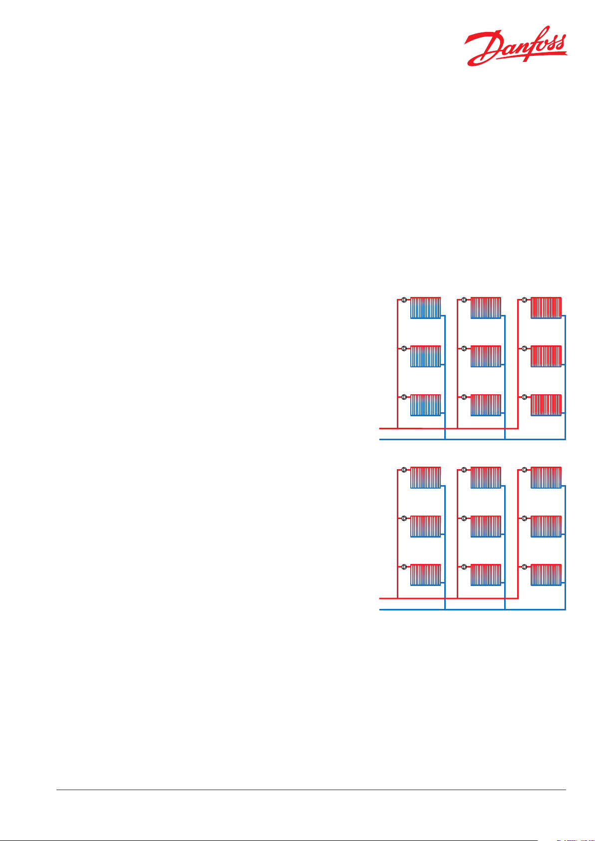
Fig. 1: Pressure and ow changes
Fig 2: Comfort with hydronic balancing
VFGWG102 © Danfoss 05/2014
1
Page 2
Technical Paper Flow and Dierence Pressure Optimize Guide
Tables
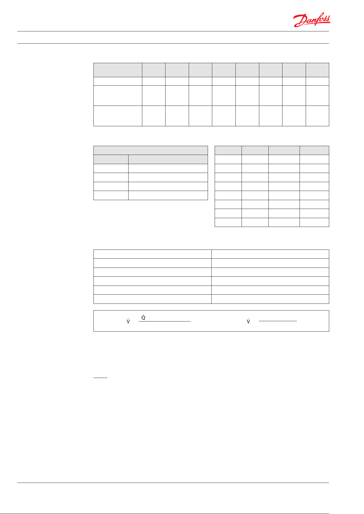
1. Heat loss (empirical values)
Yea r of
construction
Single family house 180 W/m2170 W/ m2150 W/m2115 W/m295 W/m275 W/m260 W/m240 W/m
Townhouse:
- at the end
- in the middle
Multi family house:
- up to 8 oors
- more than 8 oors
2. Dierence ow and return temperature
Typical values (K)
∆t (K) Heat source
10 -15 Heat pump
15-20 Low temperature boiler
20 -25 Condensing boiler
25-40 District energy, indirect
until
1958
160 W/m
140 W/m
130 W/m
120 W/m
2
150 W/m
2
130 W/m
2
120 W/m
2
110 W/m
1959-
1968
2
130 W/m
2
120 W/m
2
110 W/m
2
100 W/m
1969-
1973
2
110 W/m
2
100 W/m
2
75 W/m
2
70 W/m
1974 -
1977
2
2
2
2
1978 -
1983
90 W/m
85 W/m
65 W/m
60 W/m
2
2
2
2
1984-
1994
70 W/m
65 W/m
60 W/m
55 W/m
3. Presetting
RAW RA2000 living/TWA
15 20 25 1
20 25 30 2
30 30 35 3
40 40 45 4
50 50 60 5
2
2
2
2
1995-
2001
55 W/m
50 W/m
45 W/m
40 W/m
from
2002
2
35 W/m
2
30 W/m
2
33 W/m
2
33 W/m
Presetting
70 75 80 6
90 95 100 7
110 125 135 N
2
2
2
2
2
Example
Building type Multi family house
Year of construction 1984
Room size 40 m
2
Number of radiators in the room 1
Heat eect needed 55 W/m2 (according to table 1)
Dierence ow (ΔT) needed 20° C (according to table 2)
Formula:
(W/m2) x m2 x 0.86
=
∆t (K)
= ..... l/h
55 x 40 x 0.86
=
20
Presetting should be 7 (according to table 3, with RA2000).
Presetting of more radiators in the room
Two radiators in the room of same size should be
preset to:
94.6
= 4 7. 3 l /h = presetting 5 (with RA2000)
2
Are the radiators of dierent sizes, the presetting
should be calculated according to each radiator’s
area coverage.
Further calculation possibilities concerning the
radiator performance as well as the heat loss
oers the Danfoss Heating App and the DanBasicSoftware.
Note!
Corner rooms, rooms with ceiling towards the
outside and without heated oors, walls and
concrete deck directly on soil requires slightly more
eect from the radiator to provide the same comfort
as in other rooms (raise the presetting with 0.5
compared with a normal room).
= 94.6 l/h
2
VFGWG102 © Danfoss 05/2014
Page 3

Technical Paper Flow and Dierence Pressure Optimize Guide
Presetting
The presetting values of RA-DV valves can be
adjusted easily and accurately without the use of
tools (default setting = N).
Presetting can be selected in steps from 1 to 7:
• Remove protective cap / thermostatic sensor.
• Find reference mark (R).
• Turn setting ring until the aquired presetting
aligns with the reference mark.
Fig. 3: RA-DV reference mark
At setting N the valve is fully open. This setting
can be used as a ushing position, if the system
has to be ushed out because of dirt problems.
When the thermostatic sensor has been installed,
the presetting is protected against unintended
regulation.
For easy presetting a special presetting tool
(code no. 013G7830 ) is available.
Fig. 4: Presetting tool 013G7830
Pump Optimization
It is posilbe to save pump energy. Rule-of-tumb:
1/2 ow = 1/8 charging rate.
The operation is as follows:
• All RA-DV valves must be preset.
• Demount all the sensors.
• Change the current presetting of the valve at
the most unfavorable position to 2. Measure the
dierential pressure over this valve with
Danfoss ∆P tool and adjust the pressure of the
pump (g. 6).
• During the process the pressure for open and
closed valve positions are measured and the
dierence is displayed (g. 5). Lower the pump
pressure until it changes, then increase the
pressure until it does not change. Now the
desired ∆P is obtained (RA-DV ∆P min. = 0.1 bar).
• Reinstall the sensors.
• Set the heat curve on the controller (in the
heating room) at a reasonable value compared
to previous settings and in relation to dimensioning outdoor temperature = approx. 65° C
inlet temperature (according to the heat curve).
How to use the Danfoss ∆p tool
- see movie on YouTube.com
Fig. 5: Danfoss ∆p tool Fig. 6: Measure on the last radiator (valve).
VFGWG102 © Danfoss 05/2014
3
Page 4

Technical Paper Flow and Dierence Pressure Optimize Guide
Danfoss Installer App
Make balancing easy with the Danfoss Installer App!
Get it for free at App Store / Google Play or scan the QR code.
For more information on RA-DV valves, see special data sheet.
4
VFGWG102 © Danfoss 05/2014
 Loading...