

Page 1
Data Sheet
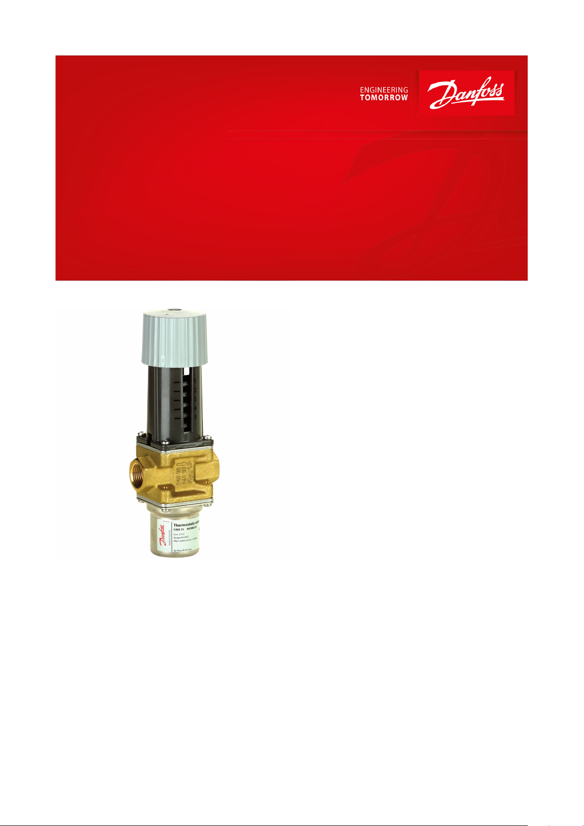
Thermostatic operated water valve
Type FJVA
With built-in temperature sensor
Thermostatic operated water valves are used
for the innite, proportional regulation of ow
quantity, depending on the setting and the
sensor temperature.
The Danfoss range of thermostatic operated
water valves includes a series of industrial
products for both cooling and heating
regulation. The valves are self-acting, i.e. they
operate without the supply of auxiliary energy
such as electricity or compressed air.
Because the valves constantly match ow
quantity to demand they are especially suitable
for temperature regulation.
The required temperature is maintained
constant with no overconsumption of:
• Cooling water in cooling systems; hot water
or steam in heating systems
• Thus operating economy is always reasonable
Features:
• Self-acting thermostatic operated water
valve, which operates without auxiliary
energy
• Opens on rising temperature of cooling water
• Valve opening degree is not aected by
cooling water pressure dierential
• Hand regulation - unique option on the
market, which saves installation time
• Regulating range dened for the point at
which the valve begins to open
AI155286424361en-000401
Page 2
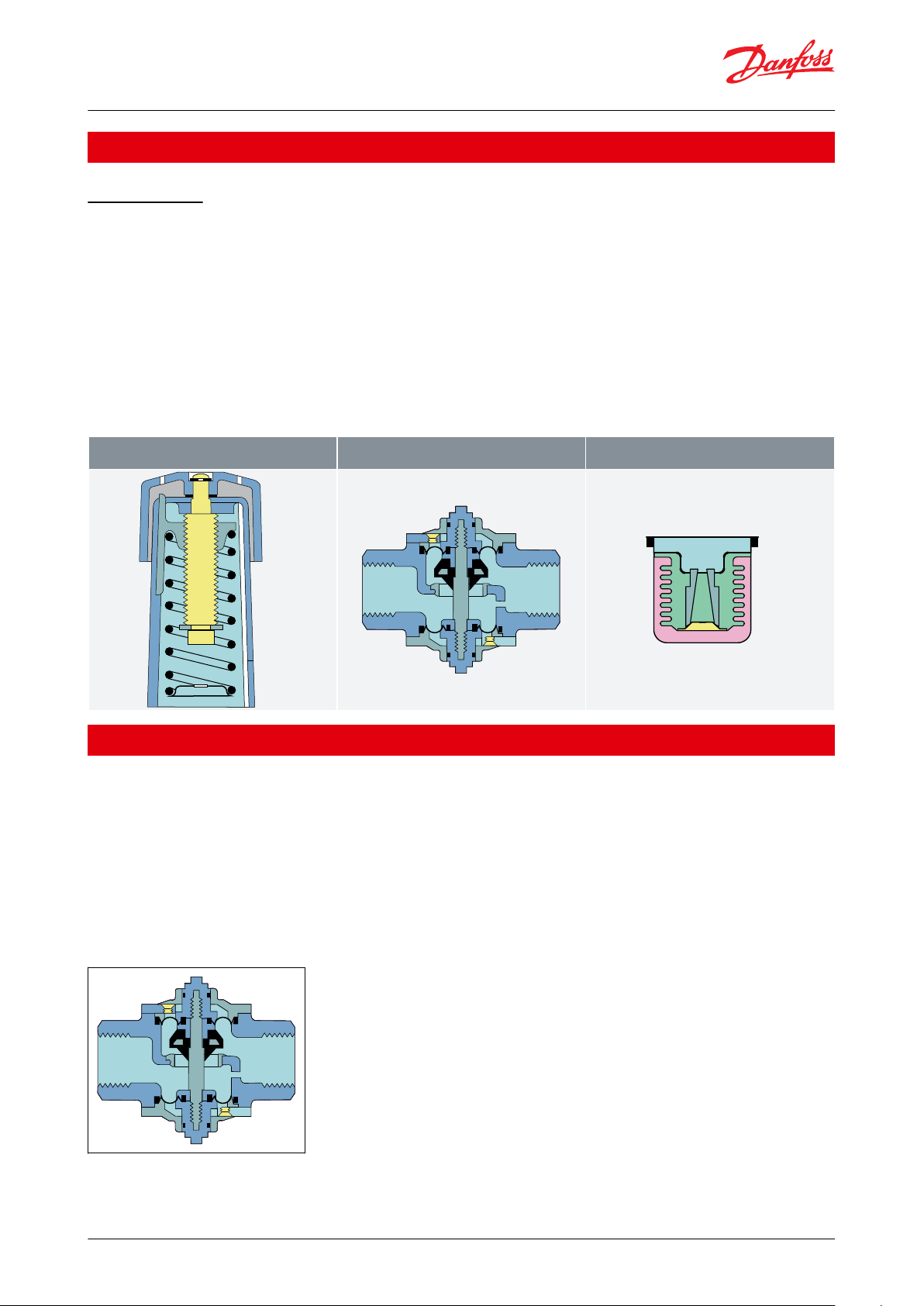
Setting section with knob,
reference spring and setting scale.
Valve body with orice,
closing cone and sealing elements.
Sensor in hermetically
sealed thermostatic element.
Danfoss
3N1101
Danfoss
3N1447
Danfoss
3N1446
Danfoss
3N1447
Thermostatic operated water valve, Type FJVA
Functions
How it works?
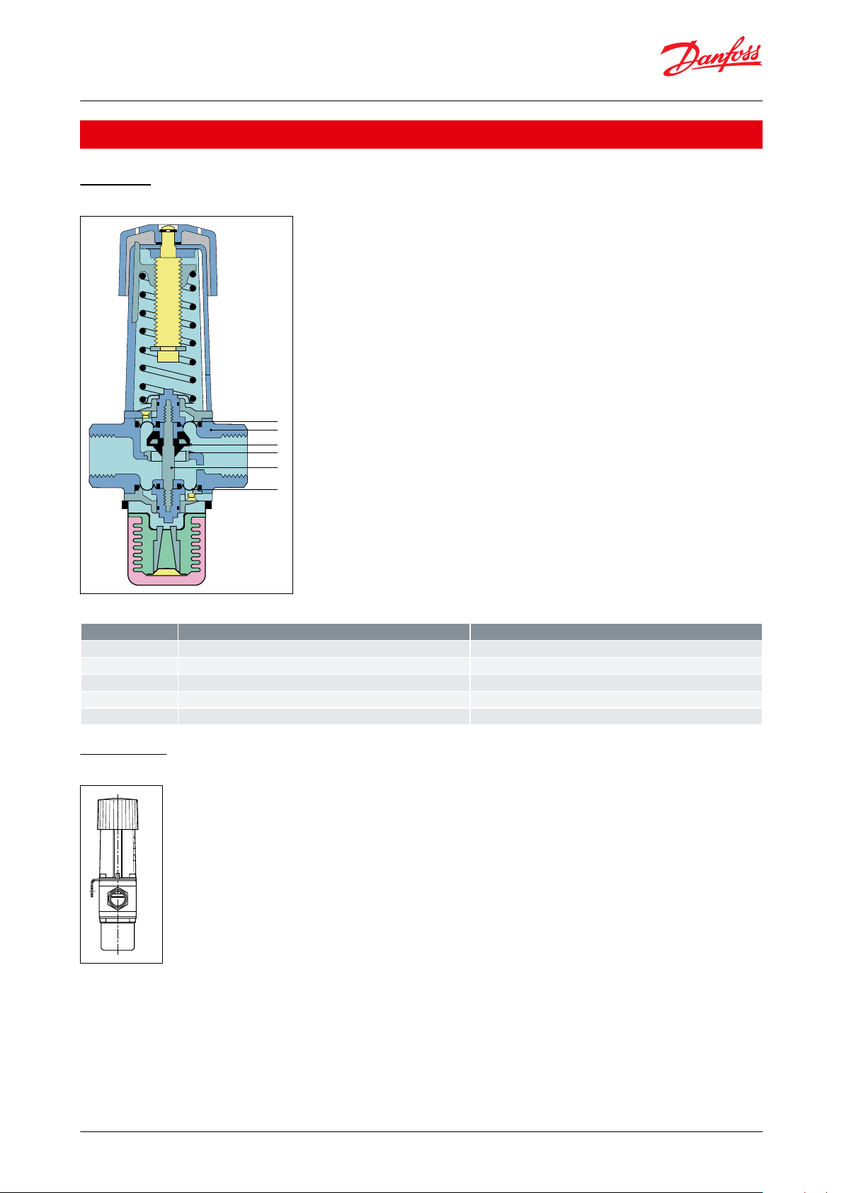
When the three elements are built together and the valve is installed, the function sequence is as follows:
1.
A temperature-dependent pressure - charge vapour pressure - builds up in the sensor.
2.
This pressure is transferred to the valve via the bellows and acts as an opening or closing force.
3.
The knob on the setting section and the spring exert a force that acts counter to the bellows.
4.
When balance is created between the two opposing forces, the valve spindle remains in its position.
5.
If the sensor temperature - or the setting - is changed, the point of balance becomes displaced and the valve
spindle moves until balance is re-established, or the valve is fully open or closed.
6.
On sensor temperature change the ow quantity change is approximately proportional.
7.
The illustrations show an FJVA cooling water valve, but the function principle applies to all types of thermostatic
valves.
Table 1: FJVA valves consist of three main elements
Applications
FJVA valves are for applications where, because of installation problems, etc., it is desirable to avoid using a capillary
tube. This applies mainly where regulation accuracy requirements are more moderate and where an integral bypass
can be accepted.
In FJVA the whole bellows element is used as the sensor. The valve reacts to the cooling water temperature and
therefore it must always be installed in the return line. Thus, indirect regulation is involved.
To ensure the medium temperature to inuence the thermostatic element, when the valve is closed, a by-pass in the
valve (see Figure 1: Valve body with by-pass) provides a constant minimal ow through the valve.
Figure 1: Valve body with by-pass
Valves of this type operate with signicantly longer time constants than AVTA valves where the sensor is located at
the point at which the temperature is to be regulated. FJVA is mainly used in systems where large and sudden load
changes do not occur.
© Danfoss | Climate Solutions | 2021.03 AI155286424361en-000401 | 2
Page 3
1
2
4
3
5
2
Danfoss
3N554
No.
Description
Material
1
Spindle
Brass2Diaphragms
Rubber - ethylene - propylene (EPDM)
3
Valve body and other metal parts
Forged brass
4
Valve cone
Nitrile rubber (NBR)
5
Valve seat
Stainless steel
Danfoss
3N554
Thermostatic operated water valve, Type FJVA
Product specication
Materials
Figure 2: Materials connected with FJVA
Table 2: Materials - parts in contact with the medium
Installation
Figure 3: FJVA installation
The valves can be installed in any position. An arrow on the valve body indicates the direction of ow. FJVA valves
are also marked so that the letters RA can be read straightforwardly. The installation of an FV lter ahead of the valve
is recommended.
If a mounting bracket is used - see Spare parts and accessories - it must always be between valve body and setting
section (see illustration).
© Danfoss | Climate Solutions | 2021.03 AI155286424361en-000401 | 3
Page 4

Q [m3/h]
Danfoss
3N492
Thermostatic operated water valve, Type FJVA
Sizing
When sizing and selecting thermo. operated water valve, it is most important to ensure that the valve is able to give
the necessary quantity of cooling water at any time, irrespective of the load. Therefore, to select a suitable size of
valve, it is necessary to know the precise amount of cooling required. On the other hand, to avoid the risk of
unstable regulation (hunting), the valve should not be oversized. The type of charge must be selected on the basis
of the temperature to be maintained, and on an assessment of the characteristics of each type, as described in the
foregoing.
In general the aim should be to select the smallest valve capable of giving the required ow.
Valve size
The following data are used when selecting valve size:
• Required cooling water ow, Q [m3/h]
• Temperature rise in cooling water, ∆t [°C]
• Dierential pressure across valve, ∆p [bar]
With fully open valve the dierential pressure should be around 50% of the total pressure drop across the cooling
system.
The following diagrams are intended to make valve sizing easier:
• Figure 4: Heating or cooling with water
• Figure 5: Relation between water quantity and pressure drop across valve
• Figure 6: Nomogram showing the valve kv range
• Figure 7: Valve ow quantity in fully open position, as a function of pressure drop Δp.
Figure 4: Heating or cooling with water
Example:
Necessary cooling output 10 kW with ∆t = 10 °C
Required ow 0.85 m3/h
© Danfoss | Climate Solutions | 2021.03 AI155286424361en-000401 | 4
Page 5

Danfoss
3N554
Thermostatic operated water valve, Type FJVA
Figure 5: Relation between water quantity and pressure drop across valve
Example:
Flow 0.85 m3/h with a pressure drop of 1.5 bar.
The kv value becomes 0.7 m3/h.
Figure 6: Nomogram showing the valve kv range
Kv values are always given for water ow in [m3/h] with a pressure drop ∆p of 1 bar.
The valve should be selected so that the necessary kv value lies in the middle of the regulation range.
Example:
FJVA 15 are the most suitable for a kv value of 0.7.
© Danfoss | Climate Solutions | 2021.03 AI155286424361en-000401 | 5
Page 6

[bar]
A
B
[m3/h]
Danfoss
3N1444
ABPressure drop across valve
Capacity with fully open valve
Danfoss
3N1444
Type
H1H
2
L
L
1
abNet weight
FJVA 15
205
1337214
G 1/2270.9
FJVA 20
205
1339016
G 3/4321.0
FJVA 25
215
1389519
G 1411.1
Thermostatic operated water valve, Type FJVA
Figure 7: Valve ow quantity in fully open position, as a function of pressure drop Δp.
Dimensions and Weights
Figure 8: Dimensions and Weights
Table 3: Dimensions and Weights
© Danfoss | Climate Solutions | 2021.03 AI155286424361en-000401 | 6
Page 7

Danfoss
3N9005
Danfoss
3N9005
Type
kv value
Bypass
(1)
Connection
Code no.
FJVA 15
1.9
ø2.0
G 1/2
003N8210
FJVA 20
3.4
ø2.0
G 3/4
003N8244
FJVA 25
5.5
ø2.5
G 1
003N8245
Type
kv value
Bypass
(2)
Connection
Code no.
FJVA 15
1.9
ø2.0
G 1/2
003N8211
FJVA 15
1.9
ø1.5
G 1/2
003N8247
FJVA 20
3.4
ø2.0
G 3/4
003N8215
FJVA 25
5.5
ø2.5
G 1
003N8216
Temperature range [°C]
Code no.
0 – 30
003N0285
25 – 65
003N0084
Designation
Description
Code no.
Danfoss
3N9002
Mounting bracket
For FJVA
003N0388
Set of 3 nitrile (NBR) diaphragms sets for mineral oil
For
FJVA 10
FJVA 15
FJVA 20
FJVA 25
003N0448
Plastic hand knob
For FJVA
003N0520
Thermostatic operated water valve, Type FJVA
Ordering
Regulation range: 0 – 30 °C
Media temperature: -25 – 55 °C
Dierential pressure: 0 – 10 bar
Table 4: Ordering
(1)
(1)
Bypass k
Bypass k
v
v
ø2.0 mm: 0.11 m3/h
ø1.5 mm: 0.06 m3/h
ø2.5 mm: 0.16 m3/h
Regulation range: 25 – 65 °C
Media temperature: -25 – 90 °C
Dierential pressure: 0 – 10 bar
Table 5: Ordering
(2)
(2)
Bypass k
Bypass k
v
v
ø2.0 mm: 0.11 m3/h
ø1.5 mm: 0.06 m3/h
ø2.5 mm: 0.16 m3/h
Spare parts and accessories
Table 6: Service elements
Table 7: Accessories
© Danfoss | Climate Solutions | 2021.03 AI155286424361en-000401 | 7
Page 8

File name
Document type
Document topic
Approvals Authority
003N9613.AB
Manufacturers Declaration
PED/RoHS
Danfoss
003N9614.AA
Manufacturers Declaration
China RoHS
Danfoss
RU Д-DK.БЛ08.В.00191_18
EAC Declaration
EAC
EAC
UA.089.D.00188-17
UA Declaration
TYSK
TYSK
Thermostatic operated water valve, Type FJVA
Certicates, declarations, and approvals
The list contains all certicates, declarations, and approvals for this product type. Individual code number may have
some or all of these approvals, and certain local approvals may not appear on the list.
Some approvals may change over time. You can check the most current status at danfoss.com or contact your local
Danfoss representative if you have any questions.
Table 8: Certicates, declarations, and approvals
© Danfoss | Climate Solutions | 2021.03 AI155286424361en-000401 | 8
Page 9

Online support
Danfoss oers a wide range of support along with our products, including digital product information, software,
mobile apps, and expert guidance. See the possibilities below.
The Danfoss Product Store
The Danfoss Product Store is your one-stop shop for everything product related—no matter where
you are in the world or what area of the cooling industry you work in. Get quick access to essential
information like product specs, code numbers, technical documentation, certications, accessories,
and more.
Start browsing at store.danfoss.com.
Find technical documentation
Find the technical documentation you need to get your project up and running. Get direct access to
our ocial collection of data sheets, certicates and declarations, manuals and guides, 3D models
and drawings, case stories, brochures, and much more.
Start searching now at www.danfoss.com/en/service-and-support/documentation.
Danfoss Learning
Danfoss Learning is a free online learning platform. It features courses and materials specically
designed to help engineers, installers, service technicians, and wholesalers better understand the
products, applications, industry topics, and trends that will help you do your job better.
Create your Danfoss Learning account for free at www.danfoss.com/en/service-and-support/learning.
Get local information and support
Local Danfoss websites are the main sources for help and information about our company and
products. Find product availability, get the latest regional news, or connect with a nearby expert—all
in your own language.
Find your local Danfoss website here: www.danfoss.com/en/choose-region.
Danfoss can accept no responsibility for possible errors in catalogues, brochures and other printed material. Danfoss reserves the right to alter its
products without notice. This also applies to products already on order provided that such alterations can be made without subsequential
changes being necessary in specications already agreed. All trademarks in this material are property of the respective companies. Danfoss and
the Danfoss logotype are trademarks of Danfoss A/S. All rights reserved.
© Danfoss | Climate Solutions | 2021.03 AI155286424361en-000401 | 9
 Loading...