

Data sheet
Return temperature limiter FJV (PN 16)
Description
Ordering
Example:
Return temperature limiter; DN 15;
kVS 1,9; PN 16; setting range
20…60°C; T
- 1× FJV DN 15 controller
Code No: 0 03 N5117
130°C; ext. thread
max
FJV is self-acting temperature controller used to
control:
- return water temperature from hot water
tanks in direct connected district heating
systems
- return water temperature in district heating
systems with mixing loop.
FJV Controller
k
Picture DN
15
20 3,4
25 5,5
Setting range
(°C)
20 … 60
VS
(m⁄h)
1,9
The FJV ensures that return water is cooled to
required temperature before it flows back to the
district heating plant. Controller closes on rising
temperature.
The controller has a control valve, thermostatic
actuator and handle for temperature setting.
Thermostatic actuator consist of a bellows only.
For block and district heating systems.
Main data:
• DN 15, 20, 25
• k
1,9; 3,4; 5,5 m⁄h
VS
• PN 16
Setting range: 20 … 60 °C
•
• Temperature:
- Circulation water / glycolic water up to 30 %:
2 … 130 °C
• Connections:
- Int. thread
- Ext. thread (weld-on and ext. thread
tailpieces)
Internal thread External thread
Connection
IS O 7/1
R
½
p
¾
R
p
1
R
p
Code No.
003N2250 G ¾ A 00 3N 5117
003N3250 G 1 A 0 03N 5118
003N4250 G 1¼ A 00 3N 5119
Connection
ISO 228/1
Code No.
Option:
- 1× Weld-on taipieces
Code No: 003H690 8
DEN-SMT/SI
Accessories
Picture Type designation DN Code No.
15 003H6908
Weld-on taipieces
External thread taipieces
20 003H6909
25 003H6910
15 R ½” 003H6902
20 R ¾” 003H6903
25 R 1” 003H6904
Service kits
Picture Type designation for Code No.
Repair set
Two diaphragms, two O-rings, one rubber cone, one tube of grease and eight
valve cover screws
Thermostatic actuator 20 … 60 °C 003N0084
VD.54 .H5.02 © Danfoss 03/2015
DN 15 003N4006
DN 20 003N4007
DN 25 003N4008
1
Data sheet Return temperature limiter FJV (PN 16)
Technical data
Application principle
Nominal diameter DN
k
value m⁄h
VS
Nominal pressure PN
Max. differential pressure bar
Medium
Medium pH
Medium temperature
Materials
Valve body internal thread
external thread
Valve seat
Valve cone
Spindle
Diaphragms, O-rings
o
15 20 25
1,9 3,4 5,5
16
10
Circulation water / glycolic water up to 30 %
Min. 7, max. 10
C
MS 58, hot-pressed, DIN 17660, W.No. 2.0401, CuZn40Pb3
Dezincing-free brass, BS 2872/CZ132
Cr Ni steel, DIN 17440, W.No. 1.4301
NBR-rubber
Dezincing-free brass, BS 2874/CZ132
EPDM-rubber
-25 … +130
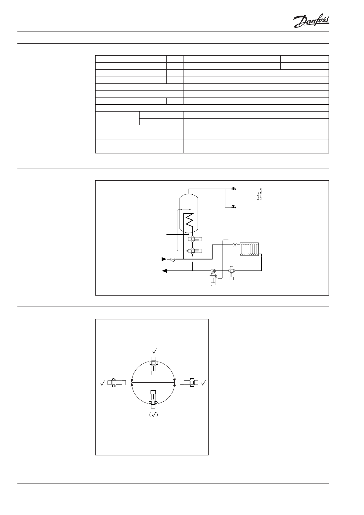
Installation positions
FJV
FJV
1. FJV must be installed immediately
behind the hot water tank.
2. If central control of return water temperature
is required (in district heating systems with
mixing loop), FJV must be positioned so that
return water temperature from hot water tank
does not affect the element.
The controller must be installed in return
line section. It is recommended that a strainer
be inserted in the system inlet line, as shown
under “Application principle” . It can be installed
in any position, with flow in the direction of the
cast-in arrow.
FJV must not be insulated as this would aect
the valve control capability – must be allowed to
give o heat.
Installation and service are described in detail
Temperature controller
in the instructions, which is supplied with the
controller. Separate instructions are available.
2
VD.54 .H5. 02 © Danfoss 03/2015
DEN-SMT/SI

Data sheet Return temperature limiter FJV (PN 16)
Sizing
Capacity diagram, P band ~ 16 K.
Control capacity Q is given for different
differential pressures p.
Ex .1
Ex.3
Ex.2
Design
1. Handle for temperature
setting
2. Spring housing
3. Setting spring
4. Spindle guide
5. O-ring
6. Valve cover
7. Diaphragm
8. Valve cone
9. Bellows stop
10. Thermostatic actuator
11. Bellows
Example no. 1
Water volume : 1,0 m⁄ h (0,28 l/s)
Differe ntial pressure: 0,05 bar (0,5 m mp v)
= 4,5 -> kVS = 5,5
k
v
Valve selection: FJV 25
Example no. 2
Water volume: 0,5 m ⁄h (0,14 l/s)
Differe ntial pressure: 0,15 bar (1, 5 m mpv)
= 1,3 -> kVS = 1,9
k
v
Valve selection: FJV 15
Example no. 3
Water volume: 0,6 m⁄ h (0,17 l/s)
Differe ntial pressure: 0,04 bar (0,4 m mp v)
= 3,0 -> kVS = 3,4
k
v
Valve selection: FJV 20
DEN-SMT/SI
VD.54 .H5. 02 © Danfoss 03/2015
3

Data sheet Return temperature limiter FJV (PN 16)
Settings
Dimensions
Temperature setting
FJV have numbered neutral scale. The drawing
shows the relation between scale numbers and
return water temperature.
Values given are indicative only.
Scale setting
Closing temperature
FJV with internal thread FJV with external thread
H
H
1
Typ e
FJV 15 71 133 72 141 149 75 R
FJV 20 71 133 90 154 164 80 R
FJV 25 76 138 95 168 167 83 R
4
VD.54 .H5. 02
mm
2
mmLmmL2mmL3mmL4mm
a
IS O 7/1
(int. thread)
½ G ¾A
p
¾ G 1A
p
1 G 1¼ A
p
b
ISO 228/1
(ext. thread)
Produce d by Danfoss A/S © 03/2015
 Loading...