

Page 1

Installation Instructions
Finger Guards
®
VLT
Soft Starter MCD 200/MCD 500
1 Product Overview
These instructions provide information about installation of
nger guard kits. The instructions are targeted at users already
®
familiar with the VLT
Starters MCD 200/202. Read the instructions before installation
and ensure that instructions for safe installation are observed.
Additional resources
Further manuals and instructions are available for download at
vlt-drives.danfoss.com/Support/Technical-Documentation/.
Soft Starters MCD 500, or VLT® Compact
2 Items Supplied
The nger guard is available in dierent kits depending on
model and enclosure size. For a list of all available kit part
numbers, refer to chapter 4.5 Packing List.
3 Safety Instructions
Finger guards t over the soft starter power terminals to
increase IP rating and prevent accidental contact with live
terminals.
WARNING
ELECTRICAL SHOCK HAZARD
VLT® Soft Starters contain dangerous voltages when
connected to mains voltage.
Models MCD5-0360C ~ MCD5-1600C: The bus bar and heat
sink are live while the unit operates (starts, runs, or stops). If
the soft starter is installed without a main contactor, the bus
bar and heat sink are live whenever mains voltage is
connected. This is also the case when the soft starter is
ready or tripped.
Improper installation of the motor or the soft starter, and
installing or servicing with power connected, can cause
death, serious injury, or equipment failure.
To avoid death, serious injury, or equipment failure:
Only use qualied electricians for carrying out the
•
electrical installation.
Disconnect the soft starter from all power sources
•
before installation or service.
Fit
•
connected.
Treat the bus bar and heat sink as live whenever
•
the unit has mains voltage connected. Also take
this precaution when the soft starter is tripped or
waiting for a command.
Follow the guidelines in these instructions and local
•
electrical safety codes.
guards to all terminals, even if no cable is
nger
Danfoss A/S © 04/2016 All rights reserved. MI17A602
Page 2
Installation Instructions
Finger Guards
®
Soft Starter MCD 200/MCD 500
VLT
4 Installation
4.1 IP20 Protection for MCD 200, MCD5-0131B
~ MCD5-0215B, and MCD5-0245C
MCD 200 and MCD 500 (enclosure sizes G2 and G3C) models
use rubber
protection when used with cable of diameter 22 mm or
greater.
guards. Rubber
nger
guards provide IP20
nger
Installation
1. Place 3 nger guards side by side in 1 retaining
bracket. Align the assembly so that the screw holes
in the bracket match the screw holes in the soft
starter.
MCD 200 only: Remove the 2 top screws from the
casing around the power terminals.
MCD 500 G3C enclosure size models only: Fit the
nger guard base chassis to the MCD 500 enclosure
rst before installing rubber nger guards.
2. Feed each power cable through the narrow end of
each nger guard. Connect the cables to the
appropriate terminals on the soft starter.
3. If the cables do not t through the nger guards,
shorten the nger guards at the narrow end to make
a bigger opening.
4. Screw the retaining bracket to the soft starter.
MCD 200 only: Use the screws from step 1 to attach
the retaining bracket to the soft starter casing.
MCD 500 G3C enclosure size models only: Fit the
nger guard cover over the nger guard base chassis
to complete the arrangement.
5. Repeat steps 1–4 for the other set of terminals.
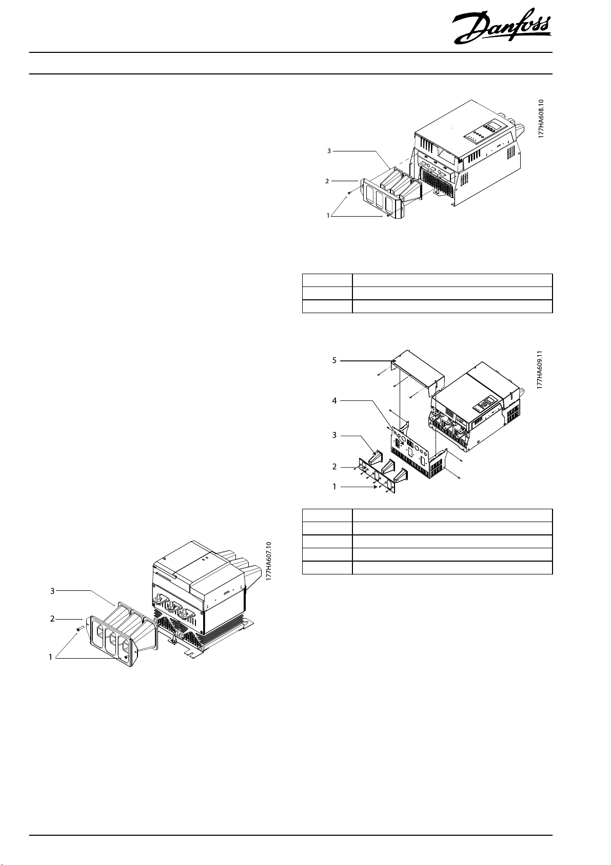
Illustration 4.2 Finger Guard Installation for MCD 500 G2 Enclosure
Size
1Screws
2 Retaining bracket
3 Finger guards
Table 4. 1 Leg en d to Illustration 4.1 and Illustration 4.2
1Screws
2 Retaining bracket
3 Finger guards
4 Finger guard base chassis
5Top cover
Illustration 4.1 Finger Guard Installation for MCD 200
2
Illustration 4.3 Finger Guard Installation for MCD 500 G3C
Enclosure Size
Danfoss A/S © 04/2016 All rights reserved. MI17A602
Page 3

Installation Instructions
Finger Guards
®
Soft Starter MCD 200/MCD 500
VLT
4.2 IP20 Protection for MCD5-0245B ~
MCD5-0961B
MCD 500 (enclosure sizes G3B and G4B) models use rubber
nger guards. Rubber nger guards provide IP20 protection
when used with cable of diameter 22 mm or greater.
Installation
1. MCD5-0245B ~ MCD5-0396B: Screw the nger guard
plate to the base of the soft starter.
MCD5-0469B ~ MCD5-0961B: Screw the nger guard
bracket to the enclosure of the soft starter.
2. Fit 1 polycarbonate retaining bracket over each nger
guard.
3. Feed each power cable through the narrow end of
each nger guard. Connect the cables to the
appropriate terminals on the soft starter.
4. If the cables do not t through the nger guards,
shorten the nger guards at the narrow end to make
a bigger opening.
5. Screw each retaining bracket to the nger guard
plate/bracket.
6. MCD-50469B ~ MCD5-0961B: Fit the nger guard
cover over the bracket to complete the arrangement.
7. Repeat steps 1–6 for the other set of terminals.
1Screws
2 Retaining bracket
3 Finger guards
4 Finger guard bracket
5Top cover
Illustration 4.5 Finger Guard Installation for MCD 500 G4B
Enclosure Size
4.3 IP20 Protection for MCD5-360C ~
MCD5-1600C
MCD 500 enclosure sizes G4C and G5C use nger guard
chassis enclosures to isolate live bus bars.
1Screws
2 Retaining bracket
3 Finger guards
4 Finger guard plate
Illustration 4.4 Finger Guard Installation for MCD 500 G3B
Enclosure Size
NOTICE
Each kit is only sucient for protection of either top or
bottom cable terminals. If both top and bottom cable
termination is used, 2 nger guard kits are required.
Installation
1. Fasten the nger guard base chassis to the main
enclosure of the soft starter using the screws
provided.
2. Drill power cable access holes into the gland plate
using the pilot holes provided. To prevent excessive
heating of the gland plate due to large eddy
currents, cut horizontal slits between the power cable
holes drilled into the gland plate.
3. Fit the gland plate to the nger guard base chassis
using the screws provided.
4. Run the power cables through the holes in the gland
plate and connect to the appropriate bus bar
terminals of the soft starter. To prevent fraying of
cables against the gland plate, t cable bushes or
glands (not supplied) appropriate for the size of
cable used.
5. Fit the nger guard cover over the nger guard base
chassis to complete the arrangement.
6. Repeat steps 1–5 for the other set of terminals.
MI17A602 Danfoss A/S © 04/2016 All rights reserved.
3
Page 4

Installation Instructions
Finger Guards
®
Soft Starter MCD 200/MCD 500
VLT
Illustration 4.6 Finger Guard Installation for MCD 500 G4C
Enclosure Size
4.4 Built-up Dimensions
Illustration 4.7 Finger Guard Installation for MCD 500 G5C
Enclosure Size
1Screws
2Gland plate
3 Finger guard base chassis
4 Finger guard cover
Table 4. 2 Leg en d to Illustration 4.6 and Illustration 4.7
A [mm (in)] 367 (14.4) 577 (22.7) 567 (22.3) 1161 (45.7) 878 (34.6) 853 (33.6) 1036 (40.8)
B [mm (in)] – – – 300 (11.8) 261 (10.3) 308 (12.1) 286 (11.3)
C [mm (in)]–––––1146 (45.1)1319 (51.9)
Illustration 4.8 Dimensions
4
ABCDEFG
MCD 200 MCD 500, G2 MCD 500, G3B MCD 500, G4B MCD 500, G3C MCD 500, G4C MCD 500, G5C
Danfoss A/S © 04/2016 All rights reserved. MI17A602
Page 5

Installation Instructions
Finger Guards
®
Soft Starter MCD 200/MCD 500
VLT
4.5 Packing List
175G9007 175G5662 175G5730 175G5731
MCD 200
1)
MCD 500 G2 enclosure size
6 nger guards (rubber) 6 nger guards (rubber) 9 nger guards (rubber) 12 nger guards (rubber)
2 retaining brackets 2 retaining brackets 9 retaining brackets 12 retaining brackets
1 installation instructions 4 M4x10 screws 2 nger guard plates 2 nger guard bracket
– 6 cable ties 18 M4x14 screws 2 nger guard cover
– 1 installation instructions 12 M4x12 screws 24 M4x16 screws
– – 1 installation instructions 12 M4x12 screws
– – – 1 installation instructions
Table 4.3 Packing List MCD 200, MCD 500 Enclosure Size G2, MCD 500 Enclosure Size G3B, and MCD 500 Enclosure Size G4B
175G5663 175G5664 175G5665
MCD 500 G3C enclosure size
2)
MCD 500 G4C enclosure size
3 nger guards (rubber) 1 nger guard grille 1 nger guard grille
1 nger guard cover 1 nger guard cover 1 nger guard cover
1 nger guard chassis 1 nger guard base chassis 1 nger guard chassis
1 clamp plate 2 nger guard side chassis 1 gland plate
11 M4x10 screws 1 gland plate 12 M4x10 screws
1 installation instructions 6 M4x10 screws 1 installation instructions
– 12 M4x16 screws –
–2 M4 nuts –
– 1 installation instructions –
1)
MCD 500 G3B enclosure size
1)
MCD 500 G4B enclosure size
2)
MCD 500 G5C enclosure size
1)
2)
Table 4.4 Packing List MCD 500 Enclosure Size G3C, MCD 500 Enclosure Size G4C, and MCD 500 Enclosure Size G5C
1) Only 1 kit required.
2) Each kit is only sucient for protection of either top or bottom cable terminals. If both top and bottom cable termination is used, 2 nger guard kits
are required.
MI17A602 Danfoss A/S © 04/2016 All rights reserved.
5
Page 6

Danfoss can accept no responsibility for possible errors in catalogues, brochures and other printed material. Danfoss reserves the right to alter its products without notice. This also applies to products already on
order provided that such alterations can be made without subsequential changes being necessary in specifications already agreed. All trademarks in this material are property of the respective companies. Danfoss
and the Danfoss logotype are trademarks of Danfoss A/S. All rights reserved.
Danfoss A/S
Ulsnaes 1
DK-6300 Graasten
vlt-drives.danfoss.com
MI17A602 04/2016
*MI17A602*
 Loading...