

Page 1
Data Sheet
FHV-A/FHV-R
Application:
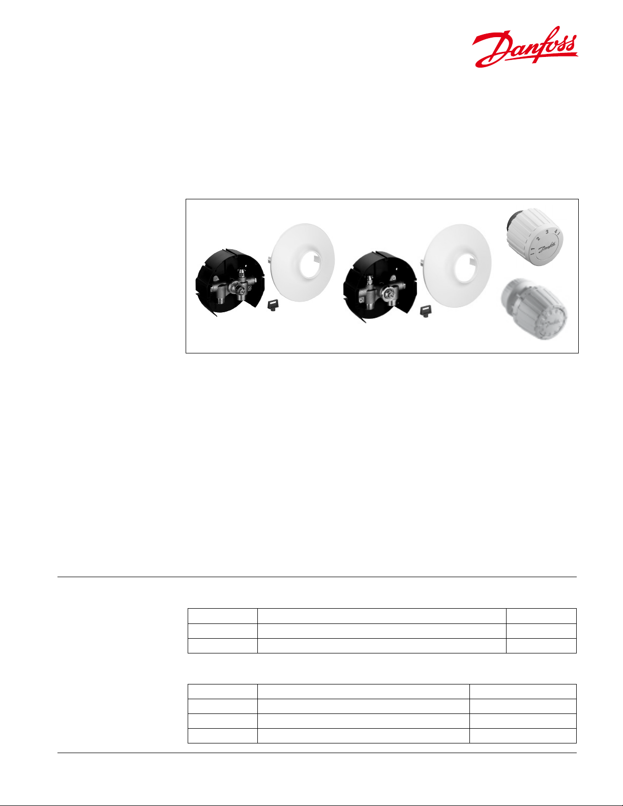
FHV-A FHV-R
Ordering
Information:
The oor-heating valve (FHV) provides an
economical method of incorporating a radiant
oor heating system into an existing hot water
or radiator system. FHV self-acting regulators
are well suited to handle underoor heating
temperature in single rooms, such as bathrooms,
entry ways or kitchens.
FHV control valves are exible to use, easily
installed and are available in two versions:
FHV-A control valves are ideally suited to control
individual underoor heated rooms. The FHV-A
is placed on the supply side of a oor heating
system, and is capable of providing hydraulic
balancing via the FHV-A’s integral pre-setting
feature. In controlling the room air temperature
a standard RA 2000 operator is tted to the
When ordering the FHV assembly order the valve body, appropriate operator, tail pieces and union nuts.
Valve bodies include wall box, cover and valve
Code No. Description Cv*
003L1001 FHV-A pre-settable valve body 0.05-0.92
003L1000 FHV-R retur temperature limiting valve 1.03
*Cv is the eater ow rat e through the fully o pen valve at a pressu re drop of 1 psi. To determi ne the pressure drop t hrough the valve at o ther ow rates use th e formula: ∆P = (Q/Cv)2, where Q = water o w in GPM
FHV-A valve.
FHV-R valves are designed for systems using
oor heating in conjunction with radiators. The
valve is place on the return side of the radiant
oor system. The valve’s operator, FJVR, senses
the return uid temperature of the system and
regulates the valve appropriately. When the
FHV-R is used for a radiant heating system,
the maximum oor heated area should not be
greater than 110 sq. ft.
Note: The ow temperature must not be
permitted to exceed the maximum supplied
water temperature as recommended by the oor
heating supplier. This can be accomplished via
use of Danfoss’ 3-way (MR) or 2-way (FTC with RA
2000 or RAVV with VMT) thermostatic valve and
a circulator in the oor heating loop.
Operators
Code No. Description Temperature Range
013G 8250 RA 2000 operator for, FHV-A 45° - 86°F (7° - 30°C)
003L10 40 FJVR operator for, FHV-R 50° - 122°F (10° - 50°C)
003L10 70 FJVR operator for, FHV-R 50° - 176°F (10 ° - 80°C)
VDUIE222 © Danfoss 10/17
1
Page 2
Data Sheet FHV-A / FHV-B Floor Heating Valve
Ordering
Information:
(Cont.):
Spare Parts
and Accessories:
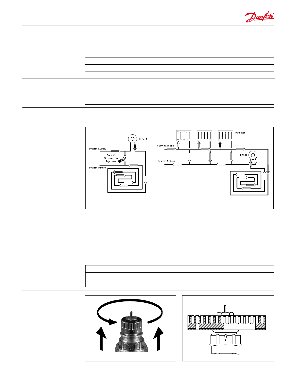
System layout:
Tail pieces and union nuts require two of each
013U0496 1/2” Union Nut
013U8608 1/2” Solder Female Tailpiece
013U0496 1/2” Male Threaded Tailpiece
Code No. Description
013G 0290 Packing gland for FHV-A
013U 0070 Packing gland for FHV-R
In laying a radiant oor heating system with the FHV valve, it is recommended to utilize the double
parallel spiral pattern otherwise known as the counter ow tube layout.
Technical
Specication:
Pre-setting:
Installed on the supply side Installed on the return side
The water supply temperature for the system
should be properly monitored to ensure the
surface temperature is appropriate for the
nished oor material.
The installation of either valves should be on a closed loop system
Maximum Flow Temperature 194 °F (90°C)
Maximum Operating Pressure 87 psi (6 bar)
Maximum Dierential Pressure (water) 8.7 psi (0.6 bar)
The maximum square footage allowed for the
FHV-R application is 110 sq. ft. Since the FHV-R
valve monitors the uid temperature and not
the air, it will not completely close. The adjusted
set temperature for the operator should be
appropriate for the nished oor material.
N
1 2 3 4 5 6 7
2
VDUIE222 © Danfoss 10/17
Page 3

Data Sheet FHV-A / FHV-B Floor Heating Valve
Design and
Function:
The incorporated pre-settable option on the
FHV-A valve body has an easy setting adjustment
ring with clearly engraved setting markers scaled
from 1-7 and N. Setting the appropriate valve is
quick and precise, without the need for a special
tool. The preset selections are in 0.5 increments
between 1 and 7, with N being in a full ow
position. (Refer to Capacity charts for ow rates)
To set the valve:
1. Remove the protective cap or sensor element
2. Lift setting ring
3. Rotate ring to the desired ow setting, and
align position with indicator located on the
collar of the valve
4. Allow setting ring to drop down into position
FHV-A
1. Pressure pin 2. Gland seal
3. O-ring seal 4. Return spring
5. Valve cone 6. Valve body
7. Connection
Materials in contact with water
Setting cylinder PPS
Spindle Ms, resistant against de-zincication
O-ring EPDM
Valve cone NBR
Pressure spring, valve spring Chrome-plated steel
Valve body, other metal parts Ms 58
FHV-R
1. Pressure pin 2. Gland seal
3. Valve cone 4. Valve body
5. Connection
VDUIE222 © Danfoss 10/17
3
Page 4

Data Sheet FHV-A / FHV-B Floor Heating Valve
Dimensions:
Dimensions for FHV-A and FHV-R
A B C D E F
2.30” 1.22” 2.00” ∅ 5.60” ∅ 6.40” 5.60”
Capacity Diagrams:
Capacity with RA 2000 operator at R-band between 0.5k and 2k.
4
VDUIE222 © Danfoss 10/17
Page 5

Data Sheet FHV-A / FHV-B Floor Heating Valve
Capacity Diagrams
(Cont.):
Capacity with FJVR operator.
Danfoss can accept no responsibility for possible errors in printed materials and reserves the right to alter its products without notice. All trademarks
in this material are property of the respective companies. Danfoss and Danfoss logotype are trademarks of Danfoss A/S. All rights reserved.
Danfoss
Toronto, ON / Baltimore, MD
Tel: 1-888-DANFOSS (326-3677) option 3
Fax: 416-352-5981
www.heating.danfoss.us
VDUIE222 © Danfoss 10/17
5
 Loading...