

Page 1
Data Sheet
FHV Regulating Valve
Application
System Lay-outs
FHV control valves are ideally suited for controlling
the temperature of individual under-oor heated
rooms and for systems using oor heating in
conjunction with radiators.
Danfoss oers the following versions:
• FHV-R provides temperature control of underoor heating circuits, using a return temperature limiting valve tted with a type FJVR
sensor element.
• FHV-A enables oor temperature control via a
presettable thermostatic valve tted with a
type RA 2000 sensor element.
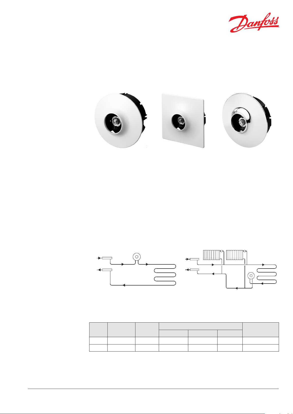
FHV-A
Floor heating system, heating circuit with FHV-A in
ow.
FHV control valves are exible to use and easy to
install in the oor heating circuit.
With the FHV-A , the integrated presetting
simplies hydraulic balancing of the system.
Connections to the ¾” external thread are made
with Danfoss compression connectors.
Note!
If using the FHV-A for room temperature control, the
ow temperature should not be permitted to exceed
the maximum recommended by the oor heating
supplier. When the FHV-R is used for controlling oor
heating, the heated oor area should not be greater
than 10 m².
FHV-R
Floor temperature control of mixed system, heating
circuit with FHV-R in return.
Technical Specications
Typ e Connection kvs (m³/ h)
FHV-R G¾A 0.88 6 bar 0.6 bar 10 bar 90° C
FHV-A G¾A 0.04 - 0.79 6 bar 0.6 bar 10 bar 90° C
VDUIC702 © Danfoss 01/2015
Working Dierential Tes t
Max. pressure
Max. ow temp.
1
Page 2
Data Sheet FHV Regulating Valve
Ordering
Accessories
FHV sets (with enclosure box and front cover) For sensor Colour Code no.
FHV-R set: return temperature limiter valve with air
vent and bleed key
FHV-A set: valve with presetting, air vent and bleed key RA2000 white 003L1001
FHV-R set: return temperature limiter valve with air
vent, bleed key and drain tap
Sensors Temp. range Colour Code no.
FJVR return temperature limiting sensor 10–50 ° C white 003L10 40
FJVR return temperature limiting sensor 10–50 ° C chrome 003L1072
RA2000 room temperature sensor with frost protection,
limiting and locking of temperature set-point
RA2000 room temperature sensor with frost protection,
limiting and locking of temperature set-point,
connection with clamping ring and Allen screw
RA2000 room temperature sensor with frost protection,
limiting and locking of temperature
Accessory Code no.
Mounting aid with integrated spirit level 003L13 38
Drain key 003L13 40
Round front cover for FHV-R / -A 003L1050
Square front cover for FHV-R / -A 003L1052
Extension piece for RA sensors, 17.9 mm 003L1035
Extension piece for FJVR sensors, 17.9 mm 003L1036
Anti theft plugs for RA2000 sensors (50 pcs.) 013G1232
Allen key for RA2000 sensors 013G1236
Threaded range limiting pins for RA2000 sensors (30 pcs.) 013G1237
Gland seal for FHV-R / -A 013G 0290
FJVR white 003L1000
FJVR white 003L1015
5–26° C white 013G299 0
5–26° C white 013G2910
5–26° C white 013G299 4
Compression Fittings
2
Compression Fitting Code no.
Compression ttings for PEX tubes, 15 x 2.5 mm 013G4147
Compression ttings for PEX tubes, 16 x 2.2 mm 013G4163
Compression ttings for PEX tubes, 18 x 2.5 mm 013G4159
Compression ttings for PEX tubes, 20 x 2.5 mm 013G4161
Compression ttings for ALUPEX tubes, 14 x 2 mm 013G418 4
Compression ttings for ALUPEX tubes, 16 x 2 mm 013G418 6
Compression ttings for ALUPEX tubes, 18 x 2 mm 013G418 8
Compression ttings for ALUPEX tubes, 20 x 2 mm 013G4190
VDUIC702 © Danfoss 01/2015
Page 3

Data Sheet FHV Regulating Valve
Presetting
Capacity Diagram
Danfoss presettable valve bodies incorporate
easy-to-use adjustment rings with clearly
engraved setting markers scaled from 1 - 7 and N.
The preset level can be selected in 0.5 increments
between 1 and 7 (see capacity diagram for ow
rates). At setting N the valve is fully open
(ushing option).
Setting values can be set quickly and precisely
without any tools:
1. Remove protective cap or sensor element.
2. Lift setting ring.
3. Turn anti-clockwise to the desired engraved
setting value.
4. Allow setting ring to spring back into position.
FHV-A & FHV-W
30 dB(A)
25 dB(A)
FHV-A with RA2000 sensor at P-band between 0.5 K and 2 K.
FHV-R
FHV-R with FJVR return temperature sensor.
VDUIC702 © Danfoss 01/2015
30 dB(A)
25 dB(A)
3
Page 4

Data Sheet FHV Regulating Valve
Design
FHV-A FHV-R
1. Pressure pin
2. Gland seal
3. O-ring seal
4. Return spring
5. Valve cone
6. Valve body
7. Connections G¾A
8. Air vent
Materials in contact with water
Setting cylinder PPS
Spindle Ms, resistant against de-zincication
O-ring EPDM
Valve cone NBR
Pressure pin, valve spring Chrome-plated steel
Other metal parts Ms 58
Dimensions
4
VDUIC702 © Danfoss 01/2015
Page 5

Data Sheet FHV Regulating Valve
Installation
FHV valves are equally suited for installation
in solid and partition walls.
All connections are made within the wall
enclosure box.
Sensor and cover are simply plugged on. An optional installation tool with spirit level
(code no. 003L1338) is available to make
assembly extra easy and reliable.
VDUIC702 © Danfoss 01/2015
5
Page 6

Data Sheet FHV Regulating Valve
6
VDUIC702 © Danfoss 01/2015
 Loading...