

Page 1
FHF-F
FHF-EA/EM
TWA
FHF-BV
FHF-EA/EM
Data sheet
Floor Heating Manifold
FHF-F
Application
The FHF-F Manifold is used for controlling water
flow in underfloor heating systems. Each pipe
in the floor heating system is connected to the
manifold, thus making it possible to control water
flow or heat supply to each room in the building
individually.
The manifold comprises of a supply and return
manifold. The supply manifold includes individual
shut-off of each circuit as well as an individual
flowmeter per circuit. The return manifold is
equipped with integrated Danfoss pre-setting
valves securing optimal hydraulic balance in the
system.
The valves can be controlled electronically by
thermal actuators or act as self-acting units by
means of remote temperature adjusters.
The manifold is supplied in modules of up to 12
outlets. Ball valves are available as an option for
positive shut-off between the manifold and the
system.
The end pieces FHF-EM and FHF-EA are supplied
with manual airvents or alternatively with automatic airvents.
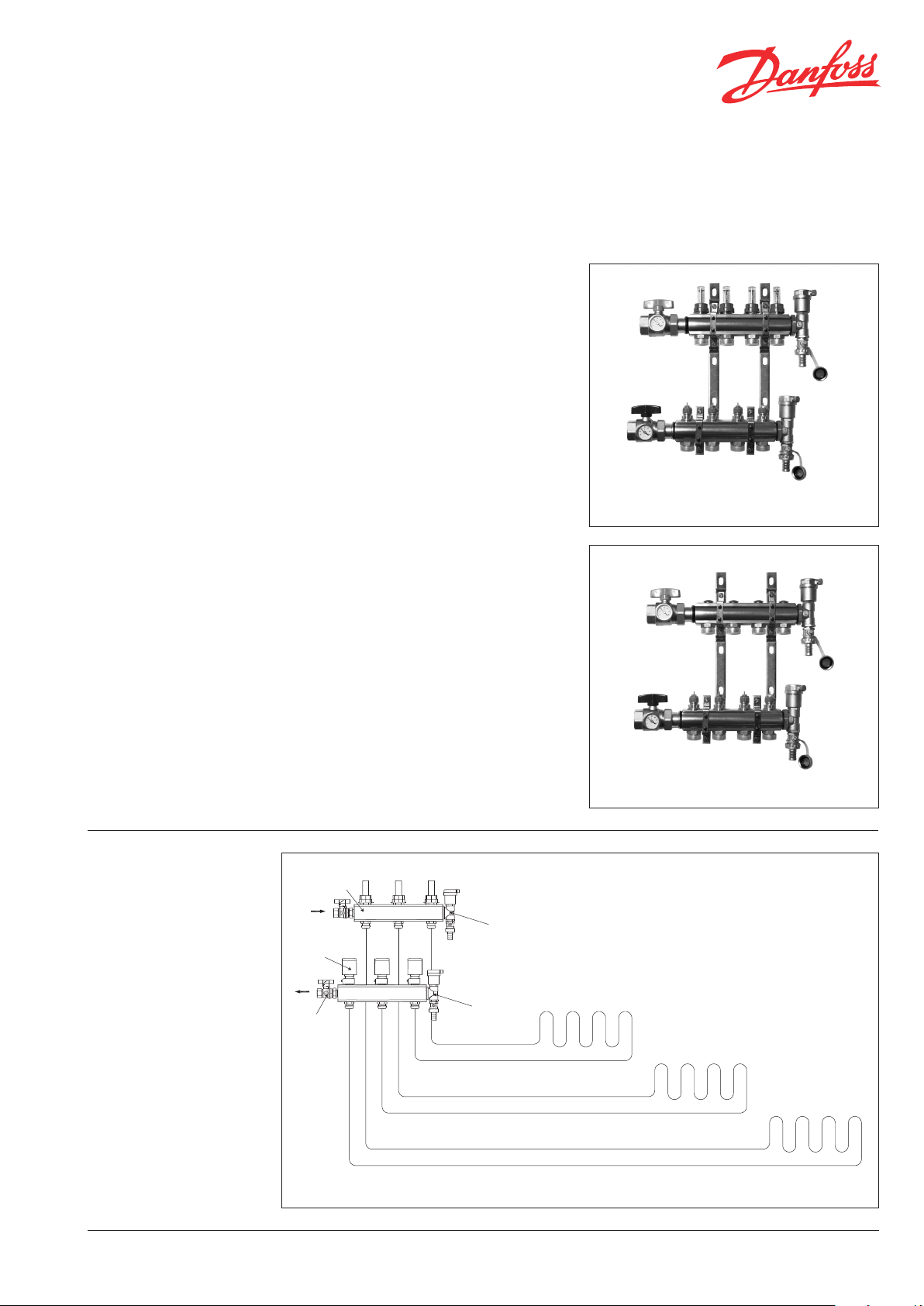
Manifold with flowmeter
Manifold without flowmeter
System layout
Danfoss FHH VD.UD.O1.12 © Danfoss 01/2010 1
Page 2
Data sheet Floor Heating Manifold, FHF-F
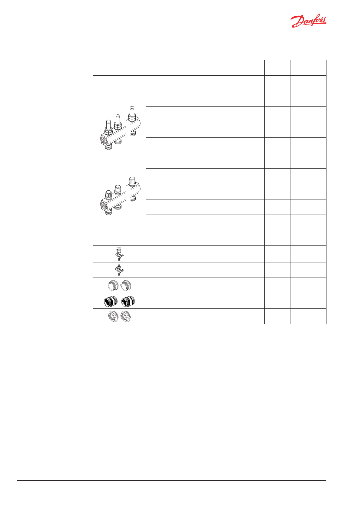
Ordering
Description Type Code no.
Manifold set 2+2, with flowmeter FHF-2F 088U052200
Manifold set 3+3, with flowmeter FHF-3F 088U052300
Manifold set 4+4, with flowmeter FHF-4F 088U052400
Manifold set 5+5, with flowmeter FHF-5F 088U052500
Manifold set 6+6, with flowmeter FHF-6F 088U052600
Manifold set 7+7, with flowmeter FHF-7F 088U052700
Manifold set 8+8, with flowmeter FHF-8F 088U052800
Manifold set 9+9, with flowmeter FHF-9F 088U052900
Manifold set 10+10, with flowmeter FHF-10F 088U053000
Manifold set 11+11, with flowmeter FHF-11F 088U053100
Manifold set 12+12, with flowmeter FHF-12F 088U053200
End section - automatic airvent and purge valve FHF-EA 088U058000
End section - manual airvent and purge valve FHF-EM 088U058100
End caps -set FHF-E 088U058200
Connection pieces - set FHF-C 088U058300
Reduction bushes/pieces -set 1" - 3/4" FHF-R 088U058400
2 VD.UD.O1.12 © Danfoss 01/2010 Danfoss FHH
Page 3
Data sheet Floor Heating Manifold, FHF-F
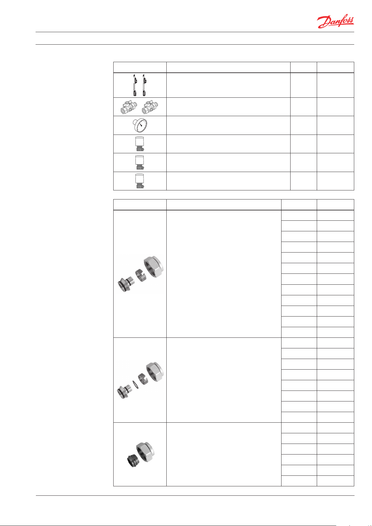
Ordering
Description Type Code no.
Mounting brackets - set FHF-MB 088U058500
2 x ball valve 1” with tail piece - for connection to
manifold and for blocking of floor heating system
1 x thermometer 0-60°C Ø35mm - for flow/return
temperature measurement
Thermal actuator, 24V, NC, Danfoss RA
connection to valve
Thermal actuator, 230V, NC, Danfoss RA
connection to valve
Thermal actuator, 24V, NC, with end switch,
Danfoss RA connection to valve
FHF-BV 088U058600
FHD-T 088U002900
TWA-A 088H311000
TWA-A 088H311200
TWA-A 088H311400
Description Type Code no.
12x2 mm 013G415200
13x2 mm 013G415300
Compression fittings for PEX tubing in
accordance with DIN 16892/16893.
14x2 mm 013G415400
15x2,5 mm 013G415500
Max working pressure - 6 bar
Test pressure – 10 bar
Max flow temp. – 95 °C
G ¾” Internal thread
Max flow temperature given by the tube
manufacturer must not be exceeded.
Compression fittings for ALUPEX tubing.
Max working pressure - 6 bar
Test pressure – 10 bar
Max flow temp. – 95 °C
G ¾” Internal thread
Max flow temperature given by the tube
manufacturer must not be exceeded.
Compression fittings for STEEL and
COPPER tubing.
Max working pressure - 6 bar
Test pressure – 10 bar
Max flow temp. – 120 °C
G ¾” Internal thread
16x1,5 mm 013G415700
16x2 mm 013G415600
16x2,2 mm 013G416300
17x2 mm 013G416200
18x2 mm 013G415800
18x2,5 mm 013G415900
20x2 mm 013G416000
20x2,5 mm 013G416100
12x2 mm 013G418200
14x2 mm 013G418400
15x2,5 mm 013G418500
16x2 mm 013G418600
16x2,25 mm 013G418700
18x2 mm 013G418800
20x2 mm 013G419000
20x2,5 mm 013G419100
10 mm 013G412000
12 mm 013G412200
14 mm 013G412400
15 mm 013G412500
16 mm 013G412600
18 mm 013G412800
Danfoss FHH VD.UD.O1.12 © Danfoss 01/2010 3
Page 4

Data sheet Floor Heating Manifold, FHF-F
Capacity/ commissioning
The pre-setting of the manifold valves determines
the flow in the floor heating pipes and is therefore an important factor for obtaining optimal
hydraulic balance in the system. Correct hydraulic
balance is important if optimal comfort is to be
achieved with minimum energy consumption and
is easily carried out following the example shown
below.
Example
Room 1 1 Determine longest pipe/largest room 25 m
2 Desired cooling (ΔT) 5 °C (typical)
3 Determine heat requirement for the room 50 W/m
4 Conversion factor 1.16
5 Calculation of flow for the room Q (l/h) = 50 W/m2 x 25 m2
5 °C x 1.16
Q (l/h) = 216 l/h
Room 2 6 Determine area of the next room 15 m2
7 Calculation of flow for the room
(ΔT and heat requirement is assumed
Q (l/h) = 50 W/m2 x 15 m
5 °C x 1.16
identical for the rooms in this case)
Q (l/h) = 129 l/h
Manifold with flowmeter
2
2
2
Pre-setting:
Room 1 N
Room 2 5
4 VD.UD.O1.12 © Danfoss 01/2010 Danfoss FHH
Page 5

Data sheet Floor Heating Manifold, FHF-F
Pre-setting the
manifold valves
Design
The diagrams show the capacities for each heating circuit at different pre-settings of the manifold
valves. Based on the above calculations and capacity diagrams each manifold valve is pre-set by
Item Description Material
1 Sightglass Heat resistant plastic
2 Flowmeter nut Brass, CuZn39Pb3
3 Flowmeter insert Brass, CuZn39Pb3
4 Supply manifold body Brass, CuZn40Pb2
rotating the red ring until the correct value on the
ring is in-line with the sight mark on the valve.
Supply manifold
with flowmeter
Return manifold
with control valve
5 O-ring EPDM
6 Union for compression fitting Brass, CuZn40Pb2
Item Description Material
1 Gland seal -
2 Pre-setting ring PBT
3 Valve body Brass, CuZn40Pb2
4 Return manifold body Brass, CuZn40Pb2
5 Kv insert Brass, CuZn39Pb3
6 O-ring EPDM
7 Union for compression fitting Brass, CuZn40Pb2
Danfoss FHH VD.UD.O1.12 © Danfoss 01/2010 5
Page 6

Data sheet Floor Heating Manifold, FHF-F
Operation conditions
Dimensions
Max differential pressure: 0.6 bar
Max working pressure: Manifold with flowmeter 6 bar
Max test pressure: Manifold with flowmeter 10 bar
Max flow temperature: 90 °C
Type 2+2 3+3 4+4 5+5 6+6 7+7 8+8 9+9 10+10 11+11 12+12
L1 (mm) 111 161 211 261 311 361 411 461 511 561 611
6 VD.UD.O1.12 © Danfoss 01/2010 Danfoss FHH
Page 7

Data sheet Floor Heating Manifold, FHF-F
Danfoss FHH VD.UD.O1.12 © Danfoss 01/2010 7
Page 8

Data sheet Floor Heating Manifold, FHF-F
8 VD.UD.O1.12 © Danfoss 01/2010 Danfoss FHH
 Loading...