

Page 1
MAKING MODERN LIVING POSSIBLE
DANFOSS HEATING
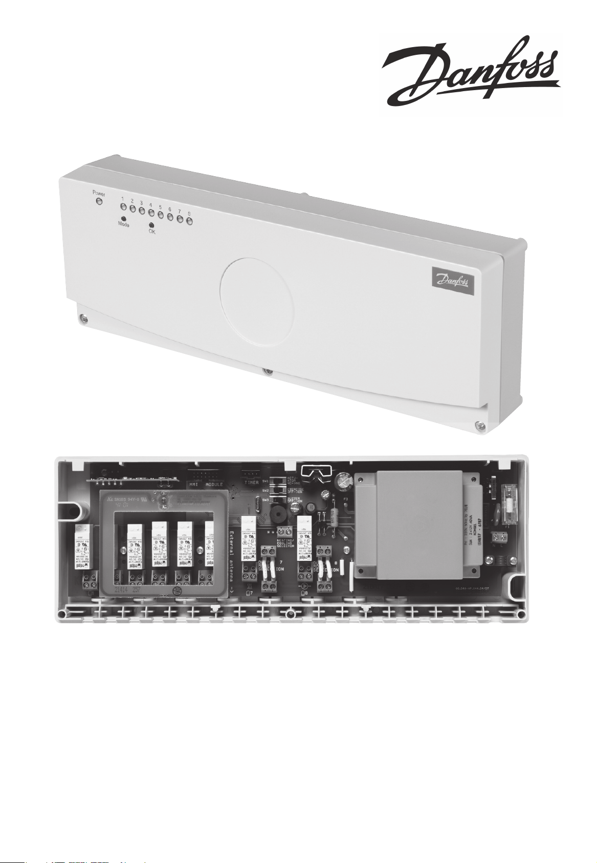
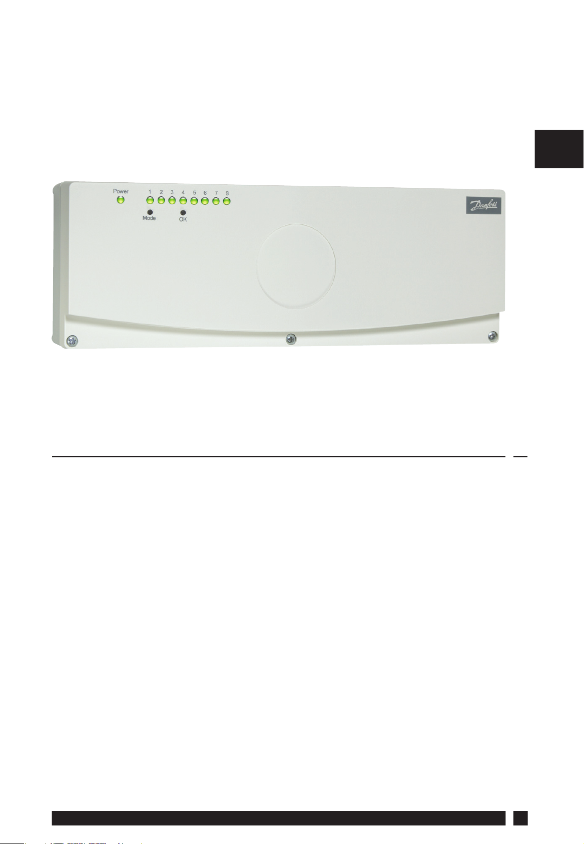
FH-BU
Electronic Programmer Interface
Installation Guide
Page 2

GB
2
FHBU
Page 3
FH-BU
Electronic Programmer Interface
GB
Index
1.0 Installation Overview .............................................................................. 4
2.0 System Overview .......................................................................................4
3.0 Installation
3.1 Wiring .....................................................................................................5
3.2 Use of Single Channel Programmer ............................................6
4.0 Notes ...............................................................................................................9
DANFOSS HEATING
3
Page 4
1.0 Installation Overview
Please Note:
This product should only be installed by a qualifi ed electrician or
competent heating installer and should be in accordance with the
GB
current edition of the IEEE wiring regulations.
2.0 System Overview
Important note: The FH-BU programmer interface is fi tted inside the lid
of the FH-BU wiring centre, and is used when an FP975-2H programmer
is being installed to provide night setback control of an under fl oor
heating system.
Cabling between the FH-BU and the remotely located FP975-2H
programmer must be carried out using double insulated cable
2
not exceeding 1mm
FP975 must be run in a separate two-core cable.
The maximum cable length between FH-BU and FP975 must not
in cross section. The power supply to the
exceed 10m.
It is important not to run the cable to the FP975 parallel to other
mains cables as these may cause interference.
Associated Products and Part Numbers
FH-BU Programmer Interface 088H782000
FP975-2H 087N759900
TS715-Si 087N789900
4
FHBU
Page 5

3.0 Installation
3.1 Wiring
Connect a three core cable between terminals 2, 3, and 6 on the
FP975-2H programmer and terminals COM, ON 1, and ON 2 on
the block on the underside of the programmer interface as per
the diagram 1.
COM
ON 2
ON 1
Diagram 1
GB
Install a link between terminal 2 and 5 on the FP975-2H wiring
back plate, diagram 2.
FP975-2H
Timer
EN
N/O N/C
L12
COM
N/C
N/O
3456
ON 2
ON 1
DANFOSS HEATING
FH-BU Programmer Interface
Diagram 2
5
Page 6

3.2 Use of Single Channel Programmer
A single channel programmer with voltage free contacts
such as the TS715 Si can be used with the FH-BU timer
interface. This can either be used to control a single zone
GB
or both zones can be linked and controlled simultaneously
(connect ON 1 and ON 2 to the same switch output).
TS715 Si controlling both zones of FH-BU
Timer
L12
N
COM
34
ON 2
ON 1
FH-BU Programmer Interface
TS715 Si controlling single zone of FH-BU
Timer
L12
N
COM
34
ON 2
ON 1
FH-BU Programmer Interface
6
FHBU
Page 7

Attach the interface to the lid of the FH-BU wiring
centre using the four screws provided, making sure the
programmer wires are hidden between the lid and the
interface leaving the ribbon cable and plug free to plug
into the base unit.
When fi tted correctly the Danfoss Randall Ltd. label will
be clearly visible on the bottom of the interface.
See diagram 3
GB
Diagram 3
Use the cable clamps in the FH-BU base unit to secure
the programmer cable.
Plug the ribbon cable into the base unit and refi t the lid
onto the base unit.
Program the FP975-2H as per the instructions packed in
the box.
DANFOSS HEATING
7
Page 8

a) Zones 1, 3, and 5 on the FH-BU are controlled by channel
1 on the FP975-2H, zones 2, 4, and 6 on the FH-BU are
controlled by channel 2 on the FP975-2H.
b) A programmed “ON” period means each zone will be
GB
controlled at the temperature set on the FH-RT room
thermostats. This is generally known as the “Comfort”
period.
c) A programmed “OFF” period means each zone will be
controlled at 4°C below the temperature set on the FH-RT
room thermostats. This is generally known as the “Setback”
period.
8
FHBU
Page 9

4.0 Notes
GB
DANFOSS HEATING
9
Page 10

GB
Notes
10
FHBU
Page 11

Notes
GB
DANFOSS HEATING
11
Page 12

Still having problems?
Call your local heating engineer:
Name:
Tel:
For problems relating to your heating controls?
Visit our website:
www.danfoss-randall.co.uk
Email our technical department:
drl_technical@danfoss.com
Call our technical department
0845 121 7505
(8.45-5.15 Mon-Thurs, 8.45-4.45 Fri)
For a large print version of these
instructions please contact the
Marketing Services Department
on 0845 121 7400.
Danfoss Randall Ltd
Ampthill Road
Bedford
MK42 9ER
Tel: 01234 364621
Fax: 01234 219705
Part No. 40650v05 02/09
 Loading...