

Application guide for ECL Comfort controllers
Get your job done swiftly
Easy selection of your
application is the key
The ECL Comfort series offers an optimum range of electronic controllers for
temperature control in heating and domestic hot water systems.
In this guide, you will find the full range of applications, intuitively described and
illustrated for you to plan and design systems with confidence.
125+
applications
covered by ECL
application keys.
www.ecl.danfoss.com

Electronic controllers from Danfoss:
Only a few products for an
endless number of applications
Based on the success and benets
of previous generations, the Danfoss
ECL Comfort 210, 296 and 310 controllers ensure comfort and convenience
for heating, cooling and domestic hot
water systems.
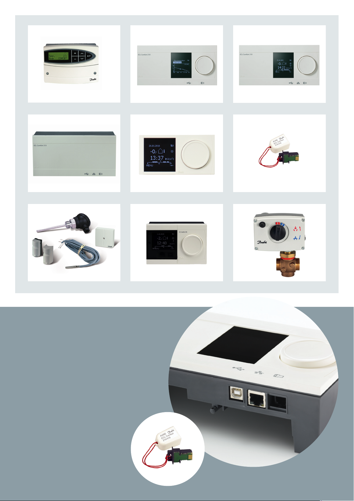
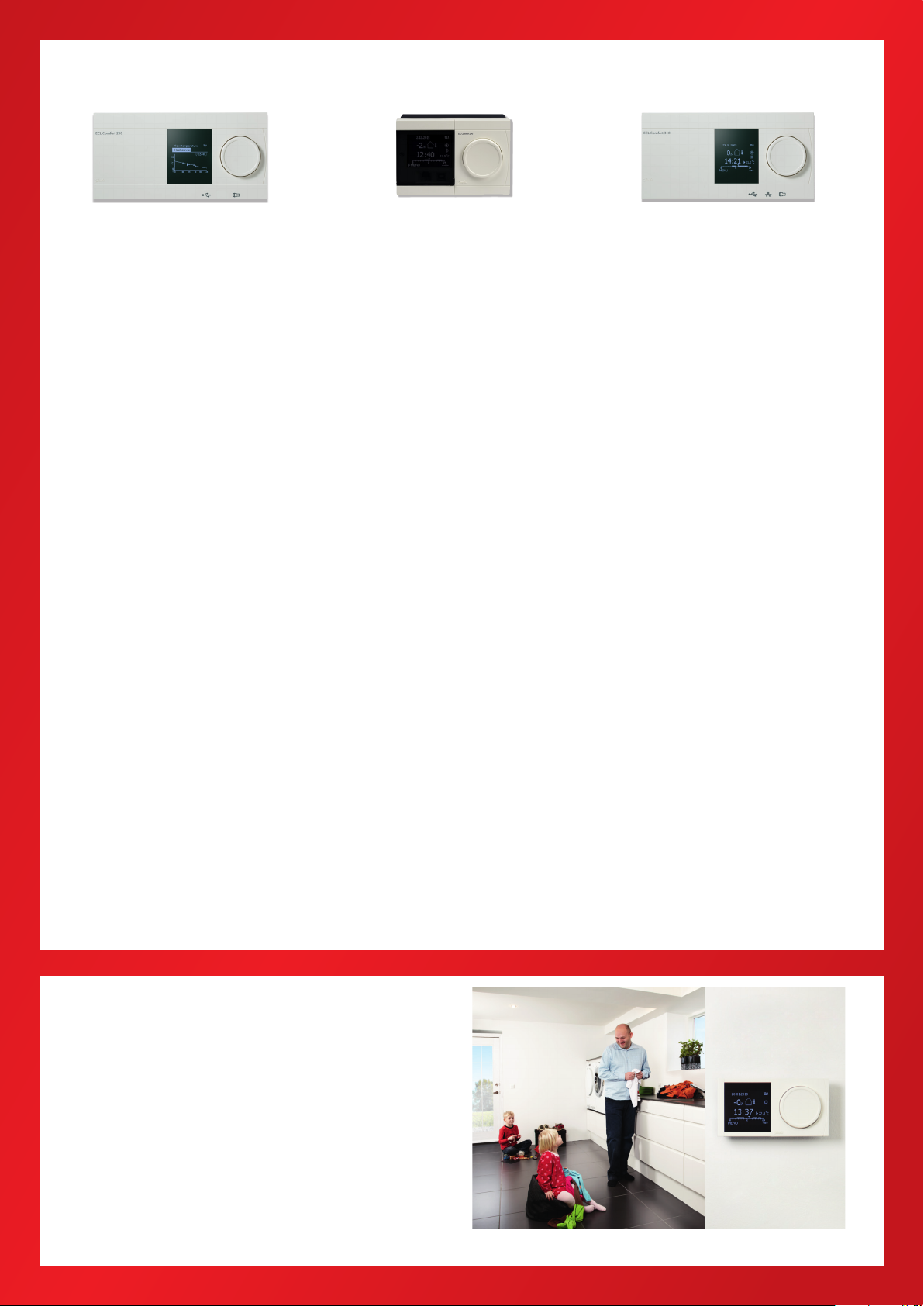
The components of ECL Comfort
The ECL Comfort range consists of ECL
Comfort 110, 210, 296 and 310 – each
in an elegant and timeless Scandinavian design.
ECL Comfort 110 is the choice for ba-
sic heating systems, for which the installer or user prefer a traditional operation.
ECL Comfort 210 appeals to users
who prefer an increased number of
options. The series oers many functional options and can be used for
commercial installations. Two control
circuits + thermostatic function, optimizer function, 3-point control of actuators, Modbus communication for
smaller SCADA systems etc.
ECL Comfort 296 covers the same as
ECL Comfort 210 and has in addition
M-bus and Ethernet connections. Furthermore, ECL 296 has the popular
size, 144 x 96 mm.
ECL Comfort 310 is the advanced con-
troller with a large number of functions, such as: Three control circuits
+ thermostatic function, optimizer
function, 3-point control of actuators,
Modbus/M-bus/Ethernet communication etc.
The intelligent key concept for ECL
Comfort 210 / 296 / 310 ensures optimum user-friendliness of these advanced controllers.
The ECL Comfort range also comprises
an elegantly designed remote control
in two versions, which can access all
parameters in the controller.
The future is in the keys
The ECL Comfort range and its advanced software key not only meet
your present demands but also the future requirements you might have for
heating control.
With ECL Comfort 210 / 296 / 310 new
demands are covered by new keys
with new settings. The few basic models and the large variety of ECL keys
give you a considerably better and
quicker overview of the unique application opportunities oered by the
ECL Comfort range. Menus are available in multiple languages.
By means of the chosen key, it is easy
to set the controller and change the
factory settings precisely to the relevant type of system and required settings.
The schedule in the ECL Comfort can
be programmed for each day in the
week. The building will be heated in
the comfort periods you request; also
holidays can be scheduled on beforehand. This is environmentally sound
and saves money.
Some features of ECL Comfort:
Optimizer and boost function
Return temperature limitation based
on outdoor temperature
Frost protection
Heating cut–out function
Year clock and automatic change over
between summer and winter time
Copy function to/from the intelligent
ECL key
Anti-bacteria function (DHW circuit)
2
2
Communication via the standardized
RS485/TCP/IP, M-bus and Modbus options
Motor protection
Automatic saving
Menus in multiple languages
Master/slave functions
Log and alarm
Holiday program
Analog input/output
Rell water function
Two pump control
Optimum control of heat
exchangers in cascade
Buer tank temperature control for
heating systems
0 - 10 Volt / PWM based speed control
of pumps
3
3

80
90
70
60
50
40
30
20
10
0
0 5
Flow rate (m
3
/h)
10 15
Time (min.)
20 25 30
Tap water temperature (°C)
The result of Auto Tuning
Sec. ow (m
3
/h)
Tap water (°C)
Automatic setup of DHW parameters
A precondition for a well functioning heating system is that the correct settings
are made before it is put to use. Adjustments are necessary to preset the control
parameters.
Presetting gives the following benets:
A high degree of comfort
Improved protection against lime deposits in DHW heat exchangers
Energy saving
Long operating life
Minimum service
The introduction of automatic setting of control parameters on the controller
itself, i.e. auto tuning and motor protection, gives optimum control of the DHW
system. This ensures a high degree of comfort, stable control during idle operation and, subsequently, longer motor life.
The setting of control parameters can thus be reduced to one easy and reliable
procedure. Auto tuning is especially necessary in DHW systems.
4
How to do auto tuning with ECL Comfort?
Open for the tap water to get a constant tapping load
Activate auto tuning by pushing a button
Wait 7-25 minutes to complete the tuning

Intelligent communication solutions
Our solutions are wide-ranging – in
every respect. We cover almost every
area of application. From busy cities
and suburbs to idyllic villages – as well
as from public or commercial buildings to residential homes.
Intelligent solutions
– intelligent communication
Danfoss communication solutions provide the ultimate in control. We don’t
just supply controllers, but unique
software which facilitates remote
monitoring and control of district heating systems. Our oering ranges from
standard software fully integratable
with the existing plant and buildings,
to complete systems with full support.
There are many good reasons to
choose a solution which allows you to
monitor, control – and therefore service – your system remotely, regardless
of whether the system services buildings in urban areas or rural communities. Danfoss has – and will supply – an
advantageous solution for you.
Your future communication platform
Remote monitoring and communication is the future as of today. Our solutions cover traditional forms of district
heating and alternatives, such as biomass plants. A Danfoss platform will
provide better, and simplied control
over a system, which not only optimizes the control processes, but also
yields savings and protects the environment. In some networks you have
large pumps and large controllers
leading to substantial energy usage.
Here it is important with an optimized
district heating network. An electronic
controller will not only simplify plant
management, it will also save energy.
Act proactive to service
Danfoss communication solutions enable you to act pro-actively to provide
better service. Thanks to ecient monitoring and alarm systems, they can
isolate and remedy problems – even
before the customer knows they exist.
For example; if the ow temperature is
incorrect, the system will automatically
activate an alarm, to warn about excessive energy consumption.
For optimum control in any system
Your requirements have been combined with our know-how to extend and
innovate our product range. Danfoss markets a comprehensive range of motorized control valves with features that give an optimum t with the ECL Comfort
controller. Our control valves are available in multiple sizes, dierent materials
and with a variety of connections. The range of motorized control valves meet
the requirements in any of these applications:
Terminal and zone
Heating and cooling
District heating
Steam
5
5

ENERGY SAVING AND
COMFORT IS A MATTER OF
OPTIMUM ENERGY CONTROL
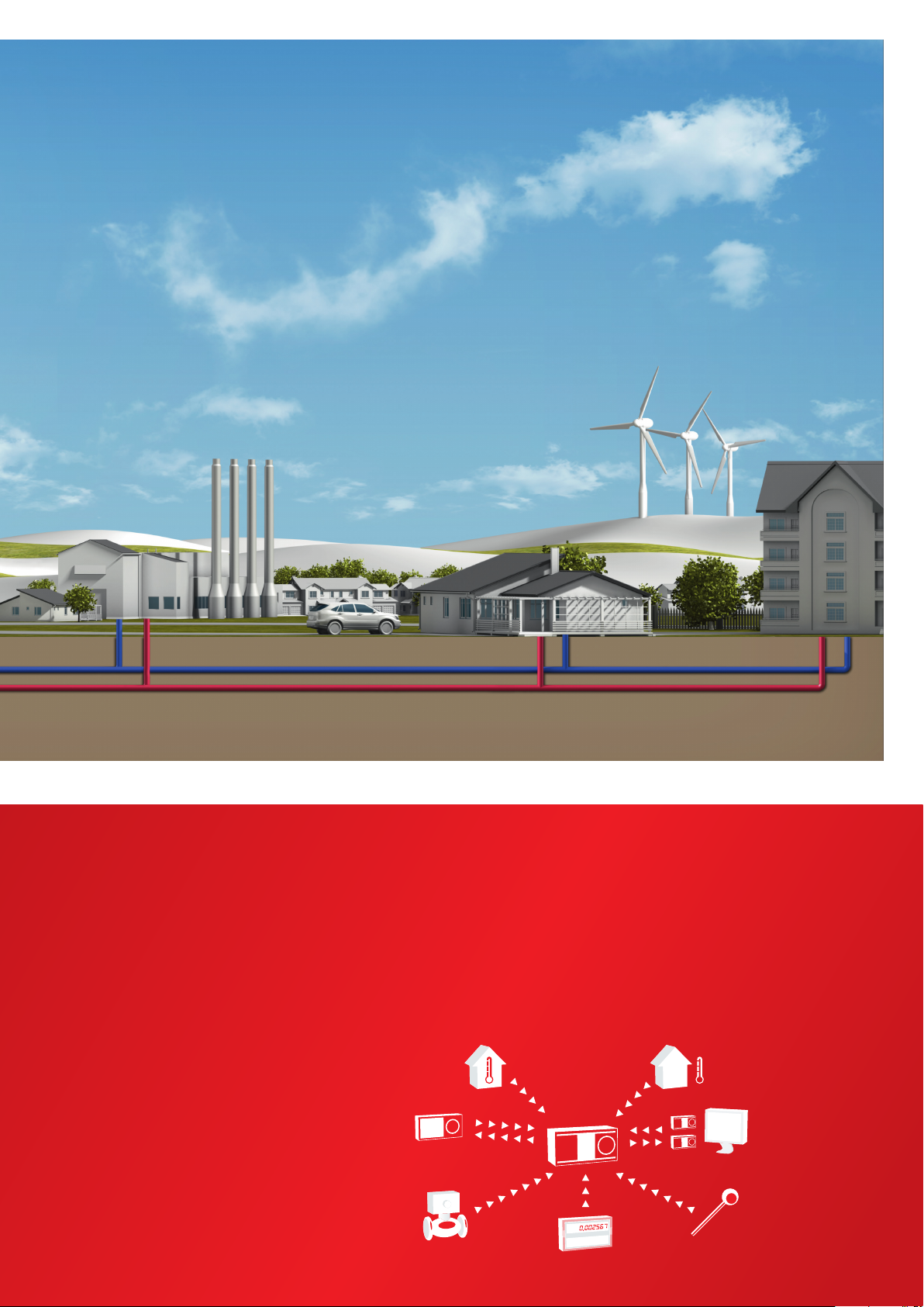
When you look at urban and rural areas with varying housing densities,
the selection of heat sources for each
individual building will dier. Where
available, district heating will most often be a part of the solution. District
heating benets the individual homeowner or tenant as well as the society
at large. Where district heating is not
available, individual solutions will be
used – preferably in combination with
renewable energy sources.
One of the solutions for achieving energy savings in any building is the use
6
6
of electronic controllers for weather
compensation. By letting the ow in
the heating system of the house reect outdoor temperatures, optimum
operation and performance of the
heating installation is obtained.
In a recently published COWI report,
the advantages of weather compensation are sound and clear: In one
family houses, the expected energy
saving is on average 10% – and in
some cases up to 40%.
What role does the ECL Comfort play?
The ECL Comfort is an electronic controller for weather compensation. By
tting typical applications for district
heating, cooling and micro network
systems including communication,
it enables you easily to optimize system performance and operation. This
leads to energy savings and longer
system life.
A correctly installed and commissioned electronic controller is the
prerequisite for a stable and wellfunctioning heating system. Easy installation and an intuitive interface
makes sure that the ECL Comfort controller is always installed correctly for
the maximum benet.
The house owners/tenants favorite
For the end-user, ECL Comfort controllers are rst and foremost equal to energy savings. Lower energy consumption, registered by the Sonometer™
connected to the ECL Comfort, and a
Room
temperature
sensor
ECL Comfort
ECA Remote
Controller
Motorized
control valves
controller
Energy meter
smaller heat bill will always be popular. The comfort level is of course still
the same, and operation is made easy
with the single dial interface which
features a modern design.
Outdoor
temperature sensor
Network
Communication
facilities
System
temperature sensor
7
7
A few steps of commissioning that put you...
Countless advantages
For successful commissioning of
the Danfoss ECL Comfort controller
only a few steps are required. It is
very straightforward, and in fact you
don't need any special programming
knowledge.
Elegant no-fuss user interface
Intuitive software makes opera-
tion a breeze
Instant feedback displayed in your
own language
Access to user data, alarms, logs
and settings
User-friendly technical documen-
tation
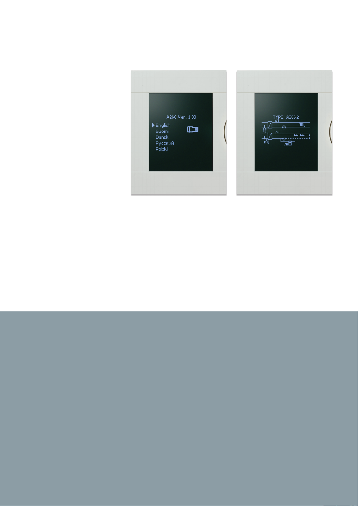
Setup wizard
– Language selection
After wiring and connecting system
components, such as pumps, actuators and temperature sensors, you can
insert the ECL Application Key. Use the
turn/push dial to select your preferred
language and follow the setup progress on the display.
Setup wizard
– Application selection
Select your application from the system application range included on
the ECL Application Key.
You can choose from applicationspecic factory settings or user-specic settings if they have been stored
on the key.
The key to easy installation
The ECL Comfort controller is matched
with a full range of ECL Application
Keys. Each Application Key is programmed with specic parameters for
a particular district heating or cooling
application.
The ingenious ECL Application Key
makes it easier than ever to install
and set up your heating system appli-
8
8
cation in the ECL controller, all without any need for advanced programming. This makes it easy to manage
and adjust your application settings.
In the event of malfunction in the
heating system the application parameters won't be aected by e.g.
power failure since they are stored in
the controller. Besides the data log-
ging facility in the ECL controller facilitates troubleshooting and keeps
system maintenance at a minimum.
The Application Key also facilitates
copying of settings to other ECL controllers in the system. This makes it
easy to adjust settings and helps ensure smooth operation and energy
optimisation for years to come.
...one step ahead of schedule
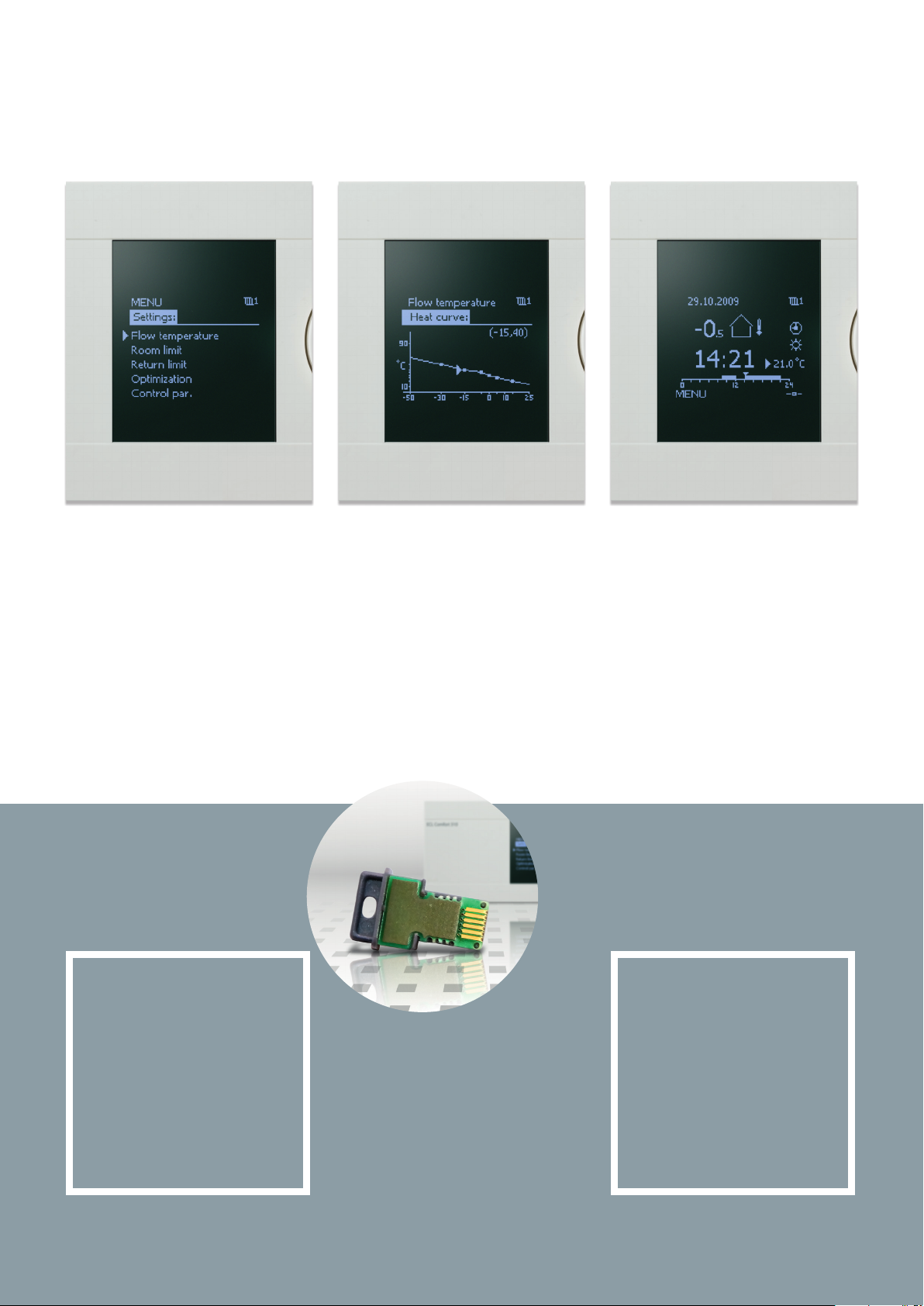
Main controller settings
The main control parameters should
be congured for optimum commissioning. They are located in the “settings” menu. Room heating and DHW
ow temperatures are set in the user
menus.
Heating curve
With six congurable coordinates
for the exible heating curve, the
ECL Comfort 210 / 296 / 310 controller
meets all requirements for achieving an accurate comfort temperature
level in the system.
Favorite display
Select your favorite display from a set
of pre-dened displays in order to get
a quick system overview. Using your
favorite display, you can perform functions such as selecting the controller
mode (scheduled, comfort, saving or
frost protection mode) and desired
comfort temperature level (room and
DHW).
One key
100% application
expertise
The data programmed in every
ECL Application Key incorporates
dedicated and applied expertise
from worldwide experience with
district heating applications.
This is your best guarantee for
optimum system performance.
No
unplanned
service visits
With correct commissioning, the
lasting durability of ECL leads to
full customer satisfaction and no
unplanned service visits.
9
9
ECL COMFORT 210 ECL COMFORT 296 ECL COMFORT 310
Stand-alone controller
for multiple heating and
cooling applications with
up to 2 circuits
2 control circuits + thermostatic
function
Intelligent ECL Application Keys,
series A2xx
Turn/push dial navigation
Large graphical display with backlight
More room for cabling
Cable box and user interface can
be separated
Two 3-point control outputs
optimized for actuators
8 inputs: 6 Pt 1000, 2 congurable
4 relay outputs
Data logging readout on display or
via USB interface
USB port for service
Modbus RS485 for short cable distances
Master/slave option
Optimized for substations and
operation in a system using Danfoss
actuators, control valves, Pt 1000
sensors and pressure transmitters
Controller with
communication
interfaces for applications
with up to 2 circuits
In addition to the features of the
ECL Comfort 210, the ECL Comfort
296 gives you:
Integrated communication
interfaces:
Modbus RS485 for longer
distances
M-bus master dedicated for
heat meters
Modbus TCP
Connection to ECL Portal – easy
to install, access and adjust /
monitor
Smaller size, 144 x 96 mm
Controller with
communication
for applications
interfaces
with up
to 3 circuits
In addition to the features of the
ECL Comfort 210, the ECL Comfort
310 gives you:
3 control circuits + thermostatic
function
Integrated communication interfaces:
USB interface for service
Modbus RS485 for longer distances
M-bus master dedicated for heat
meters
Modbus TCP
10 input: 6 Pt 1000, 4 congurable
Three 3-point control output
optimized for actuators
6 relay outputs
Data logging readout on display or
via communication interface
Connection to ECL Portal – easy to
install, access and adjust / monitor
ECL 210 summary:
Basic requirements, high
performance in district heating
systems.
ECL 296 summary:
For basic requirements, with
communication and sized
144 x 96 mm.
ECA Remote controller
– Remote Control Unit (RCU):
In case of limited access to the basement or heating
system, the ECL Comfort controller can be supplemented with a remote control unit, ECA 30/31, which
can be placed at any desired location in the building.
This enables room temperature monitoring and control, easy interfacing, and remote access for overriding all the functions of the ECL Comfort controller.
10
10
ECL 310 summary:
For high requirements – with
communication and extension
options, without programming.
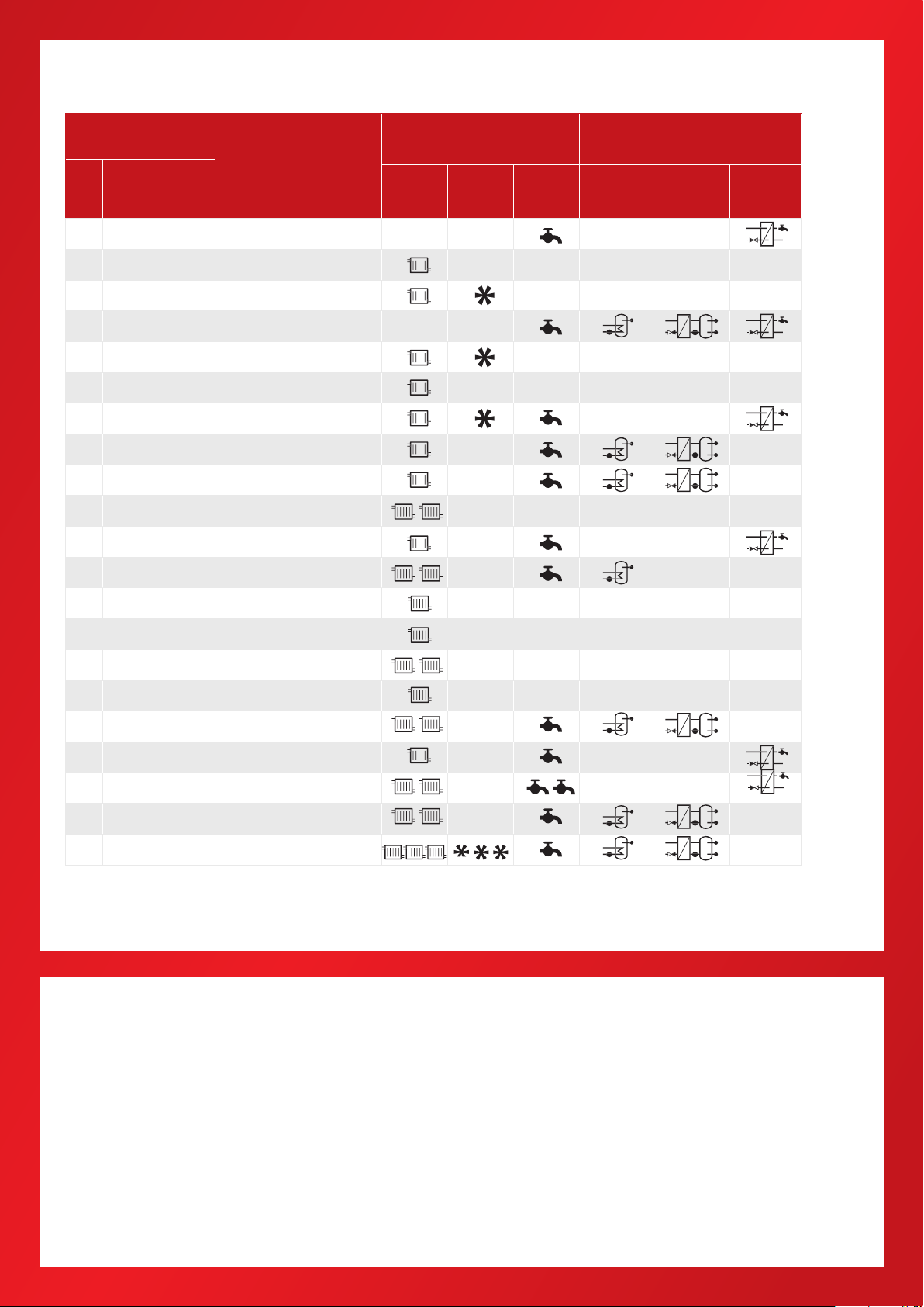
Select ECL Comfort for your application
ECL
COMFORT
ECL
ECL
110
210
ECL
296
ECL
310
ECL
Application
Key
Application
and system
type
Circuit types Domestic hot water (DHW)
designation
Heating Cooling DHW
116 DH
130 DH
A214 DH/DC ( Vent)
A217 DH
A230 DH/DC
1)
A231 DH
A232 DH/DC
A237 DH
A247 DH
A260 DH
A266 DH
A275 BOILER
1)
Storage with
internal heat
exchanger
Storage with
charging
DHW control
with HEX
Legend for ECL Application Key designation:
A = Application Key
2 = Suitable for ECL Comfort 210, 296 and 310
3 = Only suitable for ECL Comfort 310
xx = Specic application type
A319 DH
A333 DH
A361 DH
A362 DH
A367 DH
A368 DH
A376 DH
A377 DH
A390 DH
Abbreviations: DH (district heating); DC (district cooling)
Notes:
ECL Comfort 310 extension options
For applications with extended requirement the additional
internal I/O extension module ECA 32 and ECA 35 are
available.
For rell water and two pump function
For analog (0 - 10 V) control of motorized control valves,
dampers and rotating heat exchangers
Extra signal inputs
For analog (0 - 10 V) control of circulation pump speed
For PWM signal based control of circulation, charging
and control pump speed (ECA 35 only)
1)
1)
1)
= Either heating or cooling
ECL accessories and temperature sensors
Base part for mounting on wall or DIN rail
Temperature sensors (Pt 1000)
Outdoor and room
Pipe surface and immersion
11
11

Index for applications keys
ECL Comfort 110
ECL Comfort
210 296 310
Application Description Page
116
130
Electronic temperature control of DHW circuits
Electronic temperature controller for weather compensated flow
temperature control of directly or indirectly connected heating systems
14
16
Application Description Page
A214
(A314)
A217
(A 317)
A2 30.1
Heating
A230.2
Cooling
A 230.4
Heating
A231
(A 331)
A232
(A332)
A237
(A337)
A247
(A347)
A260
A266
A275
(A375)
A214 also covering A314:
Multi purpose application. Temperature control of, for e xample, ventilation sys tems with heating or cooling or a combination of these. Weather based compensation, return temperature
limitation, frost and fire protection. Optional analog control of cross-flow or rotary heat exchanger. Alarm function related to duct / flow temperature, f ire and frost.
A217 also covering A317:
Advanced temperature control of DHW circuit with storage tank, directly heated or charging system. Return temperature limitation. Optional temperature control of DHW heating
temperature.
Alarm function related to flow temperature.
Weather compensated control of flow temperature in a heating circuit. Room temperature
and wind speed compensation. Sliding return temperature limitation. Alarm function
related to flow temperature.
Control of flow temperature in a cooling circuit. Room and weather compensation. Return
temperature limitation.
Weather compensated control of flow temperature in a heating circuit. Room temperature
compensation. Sliding return temperature and power / flow limitation. Alarm function
related to flow temperature. Monitoring of temperatures in self-acting controlled DHW
circuit.
A231 al so covering A331:
Weather compensated control of flow temperature in a heating circuit. Sliding return
temperature limitation. Control of one or two circulation pumps. Optional control of flow
temperature related to supply temperature. Refill water function.
Alarm function related to flow temperature, pressure and circulation pumps operation.
Additional function in A331: Control of one or two pumps for refill water function.
A232 also covering A332 :
Weather compensated flow temperature control of heating / cooling circuit(s). Automatic
change-over between heating and cooling. Circulation pump control. Dew point (cooling
mode only) and surface temperature compensation. Return temperature limitation.
A237 also coveri ng A337:
Weather compensated control of flow temperature in heating circuit. Room temperature
compensation and sliding return temperature limitation.
Temperature control in DHW circuit with storage tank, directly heated or charging system.
Return temperature limitation. Possibility for DHW priority.
Alarm function related to flow temperatures.
A247 a lso covering A347:
Weather compensated control of flow temperature in heating circuit. Room temperature
compensation and sliding return temperature limitation.
Temperature control in DHW circuit with storage tank, directly heated or charging system.
Return temperature limitation. Possibility for sliding DHW priority.
Alarm function related to flow temperatures.
Weather compensated control of flow temperature in two heating circuits. Room temperature compensation and sliding return temperature limitation. Circuits independent in
parallel or circuit 2 after circuit 1. Alarm function related to flow temperatures.
Weather compensated control of flow temperature in heating circuit. Room temperature
compensation and sliding return temperature limitation.
Flow temperature control in DHW circuit. Return temperature limitation. Sliding DHW
priority possibility. Optional DHW temperature control related to DHW flow detection.
Alarm function related to flow temperatures.
A275 also covering A375:
Weather compensated flow temperature control of 1-stage boiler based heating systems.
One direct heating circuit and one mixing circuit. Circulation pumps control, room temperature control and sliding return temperature limitation.
Temperature control of DHW storage tank with internal heat exchanger. Frost protection
and alarm function.
The A275 application key contains applications related to ECL Comfort 310 for increased
functionalities (multiple boiler stages).
17
31
35
40
42
47
49
55
57
59
12
12

ECL Comfort
210 296 310
116
Application Description Page
Weather compensated control of flow temperature in a heating circuit, based on an
advanced buffer temperature control. Charging pump is speed controlled, based on 0 - 10
Volt or PWM (Pulse Width Modulated) signal. Discharging of buffer is avoided according
A319
A333
A361
A362
A367
A368
A376
A377
A390
to built-in logic. Differential pressure can be maintained by means of speed controlled
circulation pump (0 - 10 Volt or PWM).
Optional sliding return temperature limitation.
Relay output present for buffer heating demand; override signal for remote setting of
desired flow temperature.
Alarm functions are related to flow and buffer temperatures.
Weather compensated control of flow temperature in heating circuit. Sliding return temperature limitation. Control of one or two circulation pumps. Refill water function for one
or two pumps and refill water storage control.
Pressure and temperature monitoring functions.
Alarm function related to flow temperature, pressure and circulation pumps operation.
Weather compensated control of flow temperature in two heating circuits. Sliding return
temperature limitation. Control of one or two circulation pumps in each heating circuit.
Optional control of flow temperature related to supply temperature. Refill water function.
Alarm function related to flow temperature, pressure and circulation pumps operation.
Weather compensated control of flow temperature in a heating circuit, based on advanced cascade control of 2 heat exchangers (HEX). Control valve characteristics are taken
into consideration and flow in unused HEX circuit can be stopped.
Optional sliding return temperature limitation. Scheduled shift for inversed cascade (HEX1 - HEX-2 and HEX-2 - HEX-1) can be set. Override inputs for start of HEX-1 and HEX-2 are
available. M-Bus based signal can be used for flow / energy limitation.
Up to 6 heat exchangers can be cascade controlled by 1, 2 or 3 ECL Comfort 310 controllers, each equipped with the application key A362; the ECL controllers are interconnected
by means of the ECL 485 Bus.
Alarm functions are related to flow and flow temperatures.
Weather compensated control of flow temperature in two heating circuits. Room temperature compensation and sliding return temperature limitation. Heating circuits work
independent in parallel or circuit 2 after circuit 1.
Temperature control in DHW circuit with storage tank, directly heated or charging system.
Return temperature limitation. DHW priority.
Alarm function related to flow temperatures.
Weather compensated control of flow temperature in heating circuit. Sliding return
temperature limitation. Control of one or two circulation pumps. Optional control of flow
temperature related to supply temperature. Refill water function for one or two pumps.
Flow temperature control in DHW circuit. Return temperature limitation. Sliding DHW
priority possibility. Control of one or two circulation pumps.
Alarm function related to flow temperature, pressure and circulation pumps operation.
Weather compensated control of flow temperature in two heating circuits. Room temperature compensation and sliding return temperature limitation. Heating circuits work
independent in parallel or circuit 2 after circuit 1.
Flow temperature control in DHW circuit. Return temperature limitation. Sliding DHW
priority possibility. Optional DHW temperature control related to DHW flow detection.
Alarm functions related to flow temperatures, pressures and extra alarm input.
Optional control of motorized control valves by means of analog signal (0 - 10 volt).
Weather compensated control of flow temperature in two heating circuits. Room temperature compensation and sliding return temperature limitation. Heating circuits work
independent in parallel or circuit 2 after circuit 1.
Temperature control in DHW circuit with storage tank, directly heated or charging system.
Return temperature limitation. DHW priority. Optional temperature control of DHW heating temperature.
Alarm function related to flow temperatures.
Weather compensated control of flow temperature in up to three heating circuits. Room
tem perature compensation and sliding return temperature limitation. Heating circuits
work independent in parallel or circuit 2 and 3 after circuit 1.
Control of flow temperature in up to three cooling circuits. Room tem perature compensation and return temperature limitation. Cooling circuits work independent in parallel or
circuit 2 and 3 after circuit 1.
Temperature control of DHW tank charging circuit. Control of DHW heating temperature.
Return temperature limitation. DHW priority possibility.
Alarm functions related to flow temperatures.
Optional control of motorized control valves by means of analog signal, 0 - 10 volt, (3 x
heating circuits only).
68
69
70
71
74
77
79
83
86
13
13
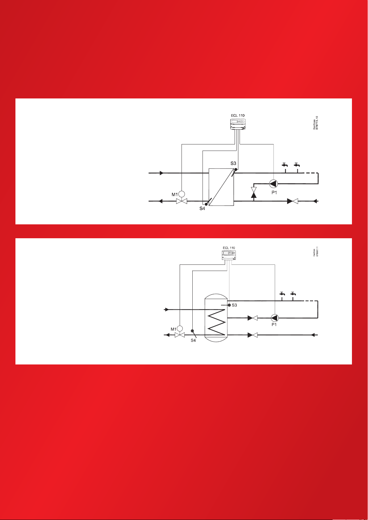
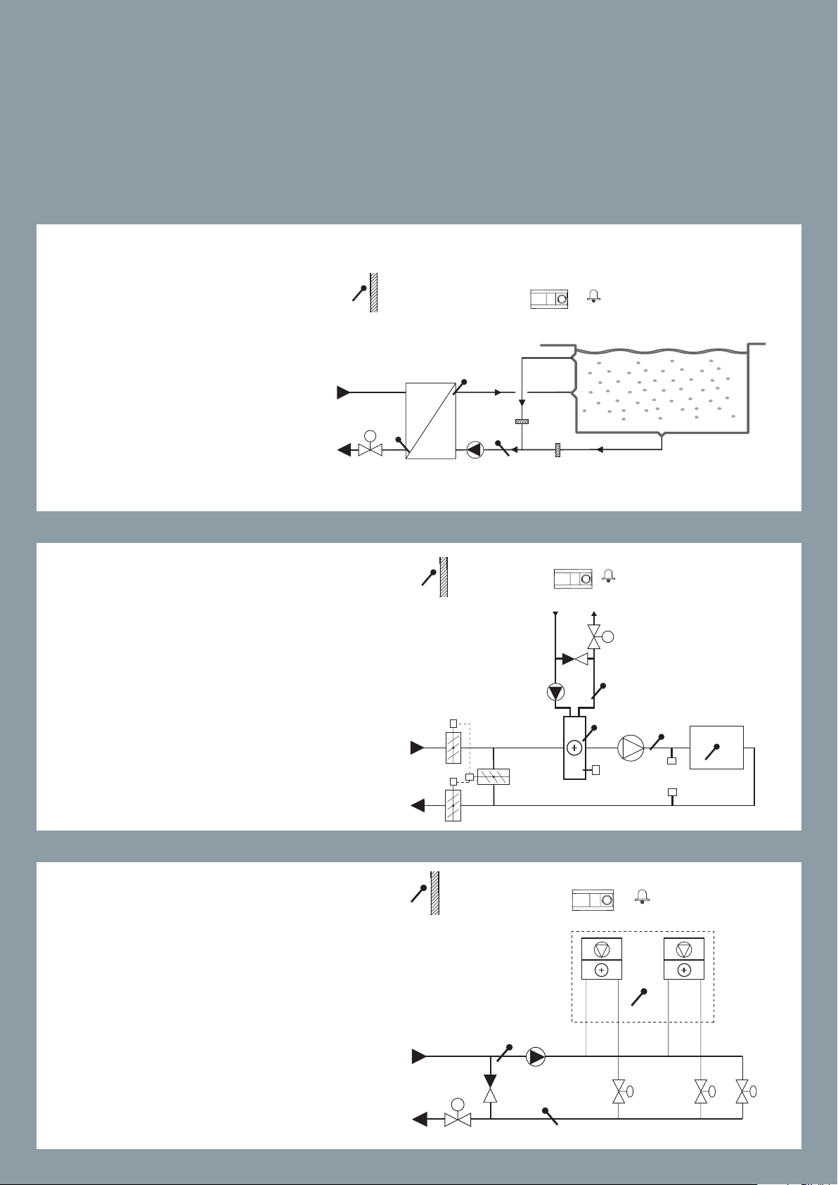
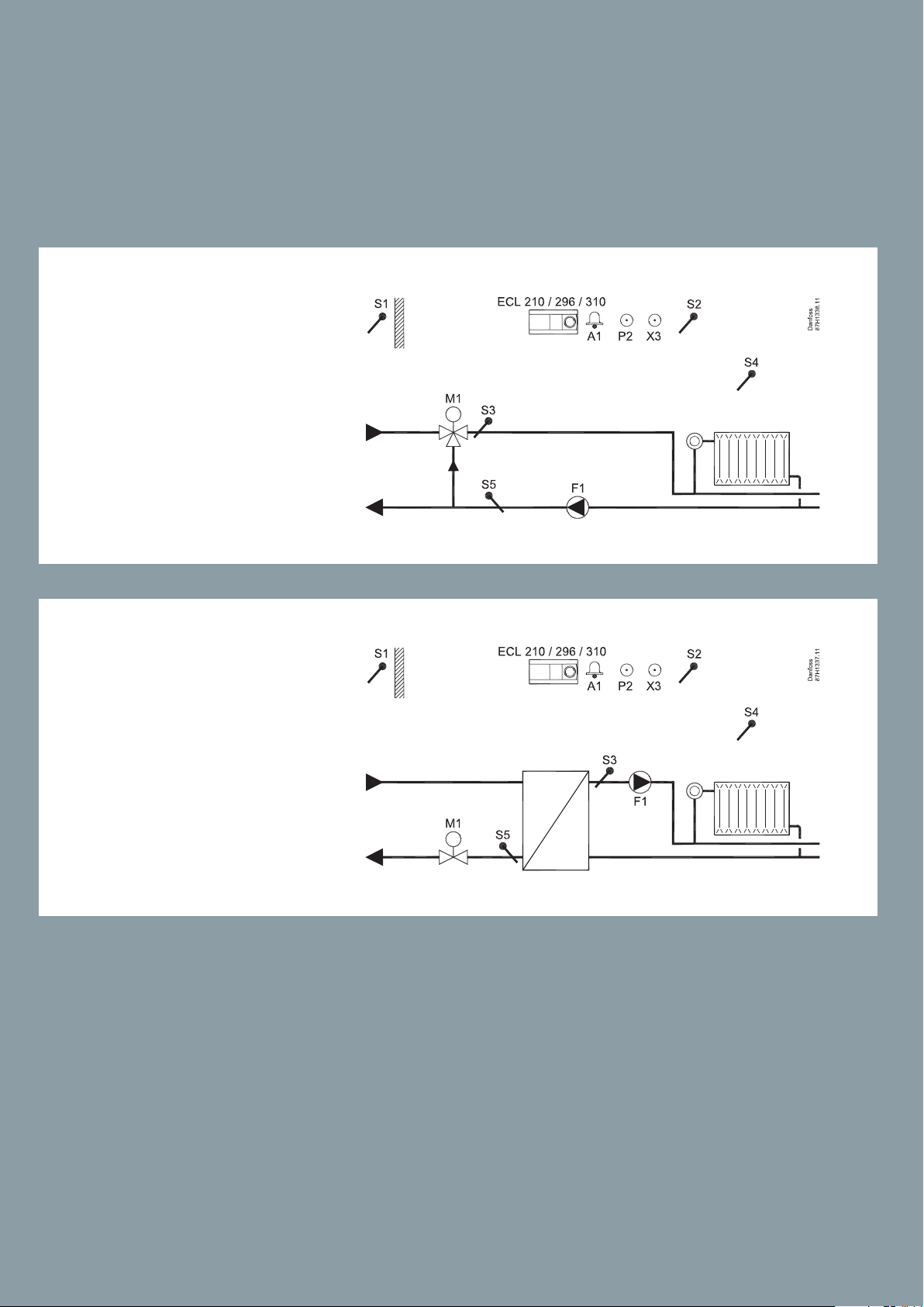
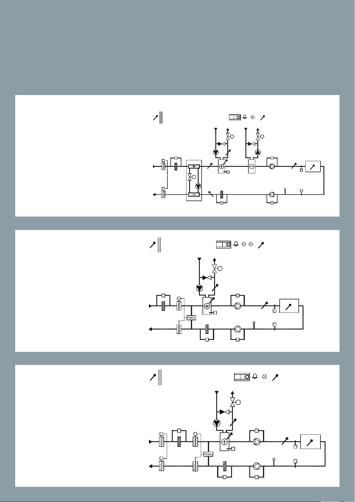
ECL Comfort 110 Application 116
Electronic temperature control of DHW circuits.
116
Example a
Constant DHW temperature control
with heat exchanger.
116
Example b
Constant temperature control of DHW
circuit with storage tank with built-in
heating coil.
14
14
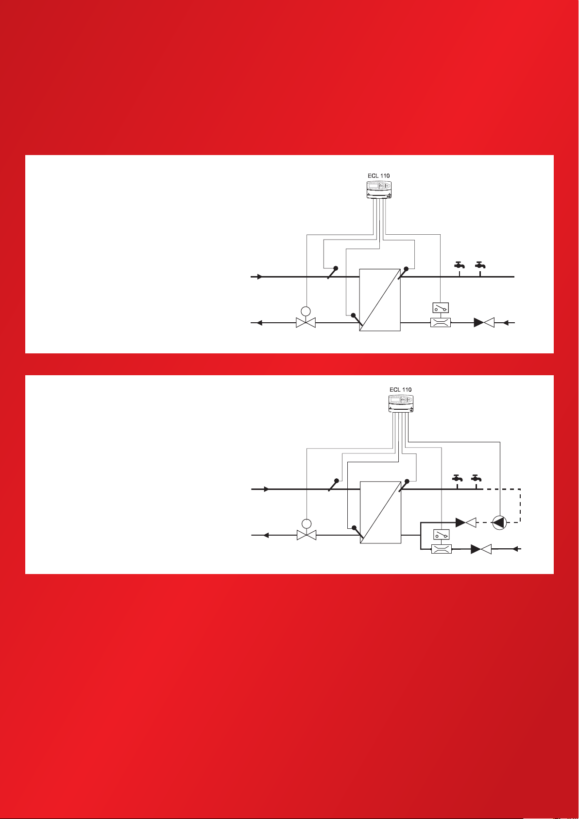
116
116
Danfoss
87H2156.10
Example c
DHW temperature control at DHW
tapping (DHW draw-o) detected by
ow switch (FS).
116
116
Example d
DHW temperature control at DHW
tapping (DHW draw-o) detected by
ow switch (FS) (DHW circulation).
M1
M1
S2
S2
S4
S4
S3
S3
FS
FS
P1
Danfoss
87H2157.10
15
15
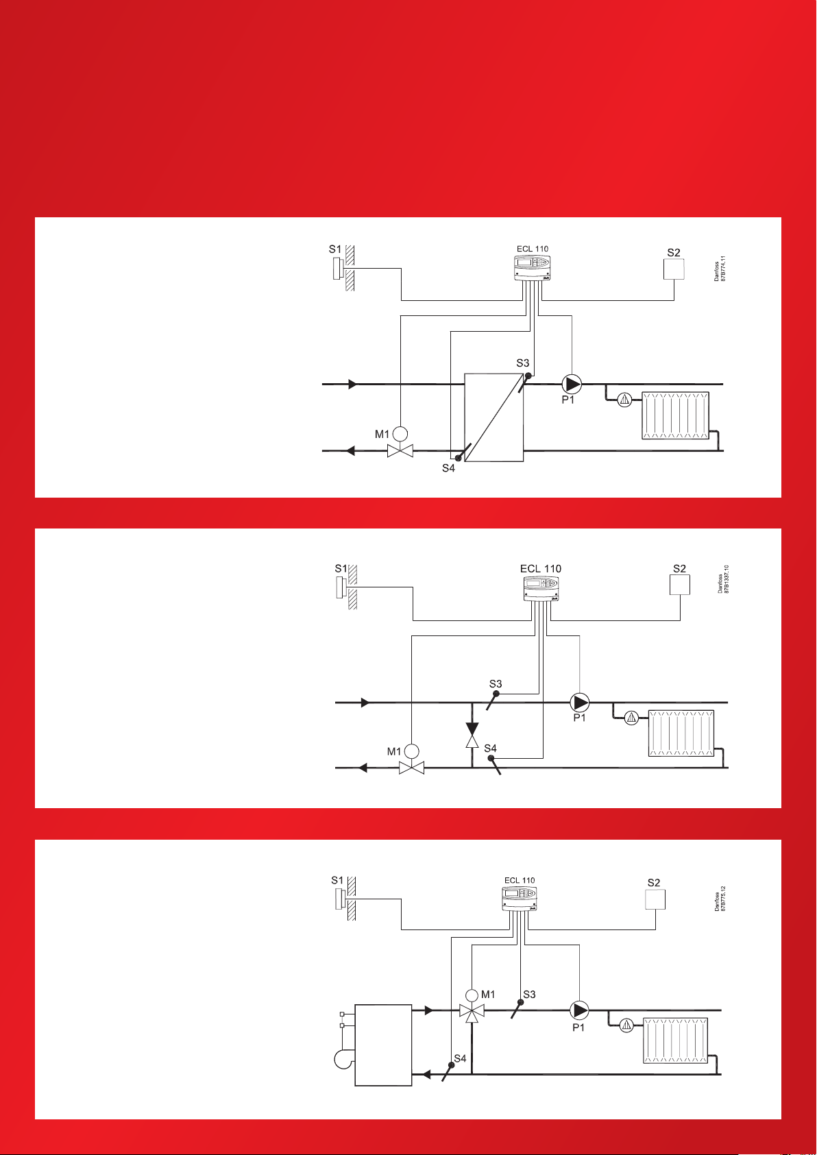
ECL Comfort 110 Application 130
Electronic temperature controller for weather compensated ow temperature.
130
Example a
District heating circuit with heat
exchanger (indirect connected
heating circuit).
130
Example b
Direct connected district heating
circuit
130
Example c
Boiler based heating circuit.
16
16
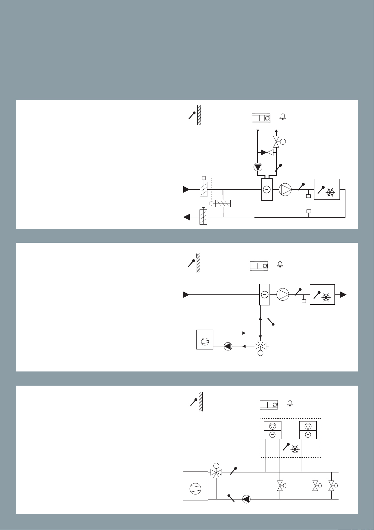
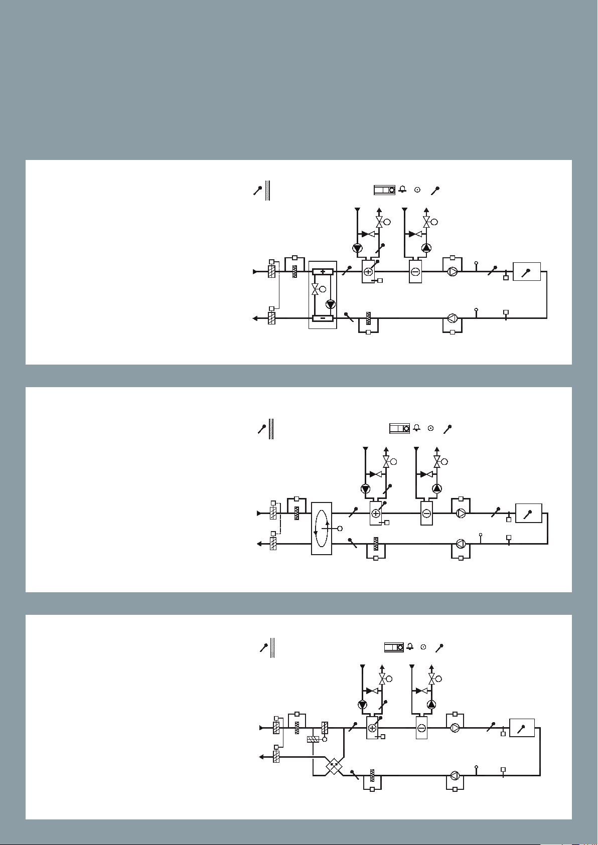
ECL Comfort 210/296/310 Application A214/A314
87H2113.13
M2
X3
Multi purpose application. Temperature control of, for example, ventilation
systems with heating or cooling or a combination of these. Weather based
compensation, return temperature limitation, frost and re protection. Optional analog control of cross-ow or rotary heat exchanger.
Alarm function related to duct / ow temperature, re and frost.
A214.1
Example a
Ventilation system with cooling and
constant room temperature control.
A214.1
S1
S1
P2
ECL 210 / 296 / 310
X3
ECL 210 / 296 / 310
S5
A1
A1
F1
F1
M2
S3
S3
S8S8S8
S4
S4
Danfoss
87H2114.13
Danfoss
Example b
Ventilation system with cooling and
constant room temperature control.
Chiller has constant ow.
A214.1
Example c
Ventilation system (fan coils) with
cooling and constant room temperature control.
S1
M2
X3
ECL 210 / 296 / 310
S3
S5
S5
A1
F1 F1
S4
S8
Danfoss
87H2115.13
17
17
F1
S1
87H2116.12
ECL 210 / 296 / 310
S1
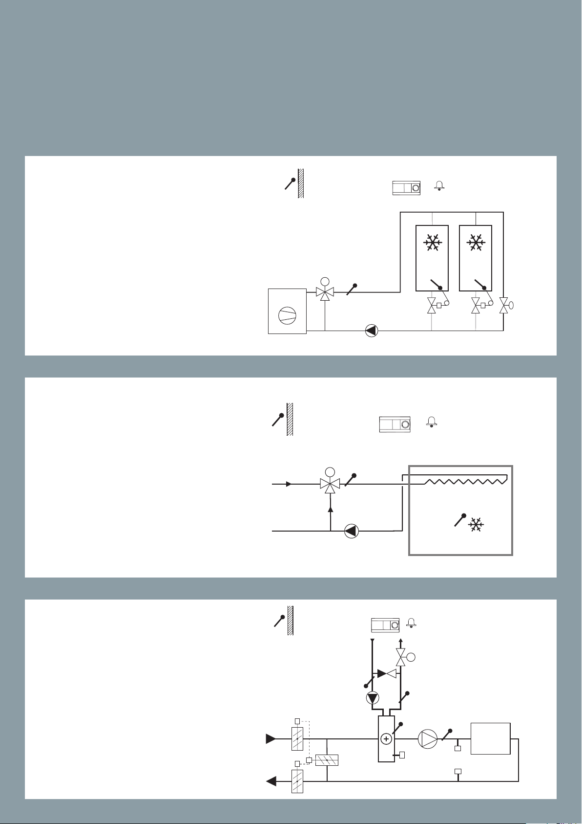
ECL Comfort 210/296/310 Application A214/A314
Multi purpose application. Temperature control of, for example, ventilation
systems with heating or cooling or a combination of these. Weather based
compensation, return temperature limitation, frost and re protection. Optional analog control of cross-ow or rotary heat exchanger.
Alarm function related to duct / ow temperature, re and frost.
A214.1
Example d
Cooling system with constant ow
temperature control.
A214.1
S1
M2
M2
S3
ECL 210 / 296 / 310
S3
A1
A1
Danfoss
Danfoss
87H2117.13
Example e
Cooling system in ceiling and constant room temperature control in
for example a wine cellar.
A214.2
Example a
Ventilation system with heating and
constant duct temperature control.
P2
F1
ECL 210 / 296 / 310
S3
X3
A1
S6
S7
S5
M1
F1
S8S8S8
S4
S4
Danfoss
87H2118.12
18
18
A214.2
S1
ECL 210 / 296 / 310
F1
ECL 210 / 296 / 310
S1
87H2120.12
S1
87H2121.12
ECL 210 / 296 / 310
Example b
Heating of a swimming pool, constant water temperature control.
M1
S5
S3
S4
A1
Danfoss
87H2119.12
A214.3
Example a
Ventilation system with heating and
constant room temperature control.
A214.3
P2
X3
A1
S6
S7
M1
S5
F1
A1
F1 F1
S4
S8S8S8
S3
Danfoss
S4
Danfoss
Example b
Ventilation system (fan coils) with
heating and constant room temperature control.
M1
S3
X3
S5
19
19
S1
87H2122.12
ECL 210 / 296 / 310
87H2123.12
ECL 210 / 296 / 310
ECL Comfort 210/296/310 Application A214/A314
Multi purpose application. Temperature control of, for example, ventilation
systems with heating or cooling or a combination of these. Weather based
compensation, return temperature limitation, frost and re protection. Optional analog control of cross-ow or rotary heat exchanger.
Alarm function related to duct / ow temperature, re and frost.
A214.4
Example a
Ventilation system with heating,
cooling and constant duct temperature control.
A214.4
Example b
Ventilation system with heating, passive cooling (outside air) and constant duct temperature control.
S1
P2
P2
M2
X3
S3
S3
X3
S6
S7
S5
M1
A1
S6
S7
S5
M1
A1
F1
F1
Danfoss
M2
S4
S8S8S8
Danfoss
S4
S8S8S8
20
20
A214.5
S1
ECL 210 / 296 / 310
87H2125.13
ECL 210 / 296 / 310
S1
ECL 210 / 296 / 310
A1
Danfoss
87H2124.12
Example a
Ventilation system with heating, cooling and constant room temperature
control.
A214.5
Example b
Ventilation system with heating, passive cooling (outside air) and constant room temperature control.
S1
P2
P2
M2
X3
X3
S6
S7
S5
M1
A1
S6
S7
S5
M1
M2
F1
S3
S8S8S8
S3
F1
S8S8S8
S4
Danfoss
S4
A214.5
Example c
Ventilation system with heating, crossow heat exchanger control and constant room temperature control.
P2
M2
X3
A1
S5
S6
S7
M1
Danfoss
87H2134.12
S3
F1
S8S8S8
S4
21
21
ECL Comfort 210/296/310 Application A214/A314
Multi purpose application. Temperature control of, for example, ventilation
systems with heating or cooling or a combination of these. Weather based
compensation, return temperature limitation, frost and re protection. Optional analog control of cross-ow or rotary heat exchanger.
Alarm function related to duct / ow temperature, re and frost.
A214.6
Example a
Heating system with 3-port mixing
valve
A214.6
Example b
Heating system with heat exchanger
22
22
A314.1
S1
87H2133.12
S1
ECL 310
87H2127.12
ECL 310
+ ECA 32
A1
M1
S2
Danfoss
Example a
Ventilation system with heating, passive cooling (outside air) and constant
duct temperature control. Analog controlled passive cooling (M2).
A314.1
Example b
Ventilation system with heating, cooling and constant duct temperature
control. Analog controlled cooling
(M2).
P2
P2
S3
X3
M2
S3
X3
A
ECL 310
+ ECA 32
M1
S5
S6
S7
S6
S7
S5
A1
F1
S4
S8S8S8
S2
M2
A
F1
S4
S8S8S8
Danfoss
87H2128.12
A314.2
Example a
Ventilation system with heating, passive cooling (outside air) and constant
room temperature control. Analog
controlled passive cooling (M2).
S1
P2
M2
S2
S6
S7
S5
A1
M1
F1
S3
S8S8S8
+ ECA 32
X3
A
S4
Danfoss
23
23

S1
ECL 310
S1
87H2132.12
ECL 310
S1
87H2131.12
ECL Comfort 210/296/310 Application A214/A314
Multi purpose application. Temperature control of, for example, ventilation
systems with heating or cooling or a combination of these. Weather based
compensation, return temperature limitation, frost and re protection. Optional analog control of cross-ow or rotary heat exchanger.
Alarm function related to duct / ow temperature, re and frost.
A314.2
Example b
Ventilation system with heating,
cooling and constant room temperature control. Analog controlled cooling (M2).
A314.3
P2
S10
X3
S6
S7
M1
S5
+ ECA 32
+ ECA 32
A1
A1
M1
S2
M2
A
F1
S3
S8S8S8
S2
S4
Danfoss
87H2135.12
Danfoss
Example a
Ventilation system with heating and
constant room temperature control.
Analog controlled fan speed (V1)
based on outdoor wind speed.
A314.3
Example b
Ventilation system with heating and
constant room temperature control.
Analog controlled air curtain (V1)
speed based on outdoor wind speed.
A1
S6
S7
S6
S5
S7
S5
F1 / V1
M1
F1
S8S8S8
S2
S3
S8S8S8
S3
S4
Danfoss
V1
A
S4
X3
P2
ECL 310
+ ECA 32
S10
X3
P2
24
24
A314.4
Example a
Ventilation system with heating, passive cooling (outside air) and room
temperature control. Analog controlled speed of fans in relation to
pressures. Analog controlled speed
of rotary heat exchanger (M2) for
heat recover y.
A314.4
Example b
Ventilation system with heating, passive cooling (outside air) and room
temperature control. Analog controlled speed of fans in relation to
pressures. Analog controlled damper
(M2) for heat recovery by means of a
cross heat exchanger.
A314.4
Example c
Ventilation system with heating, passive cooling (outside air) and room
temperature control. Analog controlled speed of fans in relation to
pressures. Analog controlled speed
of rotary heat exchanger (M2) for heat
recovery. Control of Night damper P8
for reduced ventialtion during saving
periods.
25
25
ECL Comfort 210/296/310 Application A214/A314
Multi purpose application. Temperature control of, for example, ventilation
systems with heating or cooling or a combination of these. Weather based
compensation, return temperature limitation, frost and re protection. Optional analog control of cross-ow or rotary heat exchanger.
Alarm function related to duct / ow temperature, re and frost.
A314.4
Example d
Ventilation system with heating, passive cooling (outside air) and room
temperature control. Analog controlled speed of fans in relation to
pressures. Analog controlled damper
(M2) for heat recovery by means of
a cross heat exchanger. Control of
Night damper P8 for reduced ventilation during saving periods.
A314.4
Example e
Ventilation system with heating, passive cooling (outside air) and room
temperature control. Analog controlled speed of fans in relation to
pressures. Analog controlled valve
(M2) for heat recovery by means of a
Fluid battery. Control of Night damper P8 for reduced ventilation during
saving periods.
A314.5
Example a
Ventilation system with heating, passive cooling (outside air) and room
temperature control. Analog controlled speed of fans in re lation to
air quality (CO2). Analog controlled
speed of rotary heat exchanger (M2)
for heat recovery.
26
26

A314.5
Example b
Ventilation system with heating, passive cooling (outside air) and room
temperature control. Analog controlled speed of fans in re lation to
air quality (CO2). Analog controlled
damper (M2) for heat recovery by
means of a cross heat exchanger.
A314.5
Example c
Ventilation system with heating, passive cooling (outside air) and room
temperature control. Analog controlled speed of fans in re lation to
air quality (CO2). Analog controlled
speed of rotary heat exchanger (M2)
for heat recovery. Control of Night
damper P8 for reduced ventilation
during saving periods.
A314.5
Example d
Ventilation system with heating, passive cooling (outside air) and room
temperature control. Analog controlled speed of fans in re lation to
air quality (CO2). Analog controlled
damper (M2) for heat recovery by
means of a cross heat exchanger. Control of Night damper P8 for reduced
ventilation during saving periods.
27
27
27
87H1343.11
Danfoss
S1
S2
A1 X4
P2
ECL 310
+ ECA 32
S10
M2
S13
S14
A
X3
M1
S5
S6
S7
S10
S9
F1 / V2
S12
S3
S8
S8
S4
S9
F1 / V3
S11
M3
X5
87H1344.11
Danfoss
S1
S2
A1
X4
P2
ECL 310
+ ECA 32
S10
S13
S14
X3
M1
S5
S6
S7
S10
S9
F1 / V2
S12
S3
S8
S8
S4
M2
A
S9
F1 / V3
M3
S11
X5
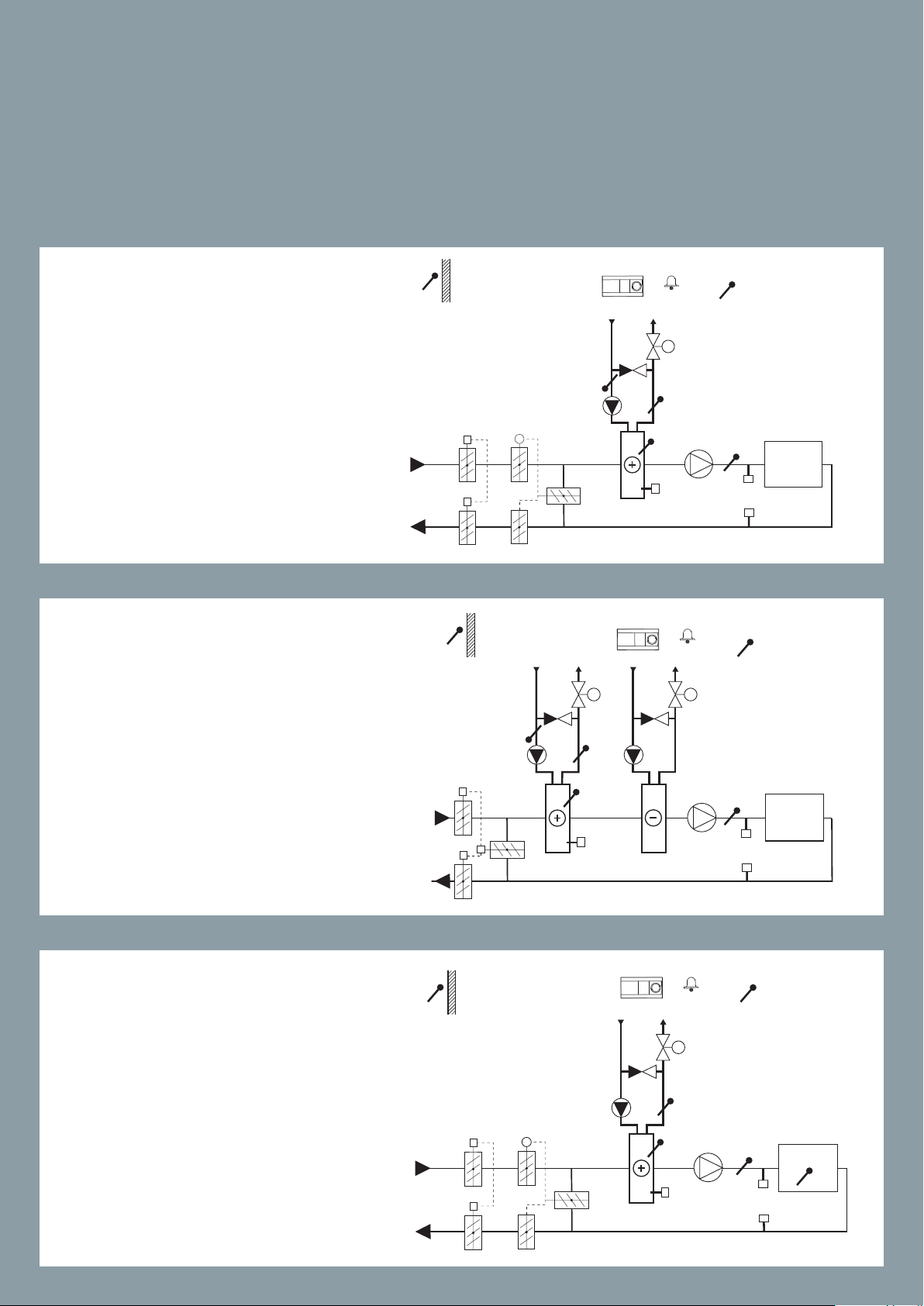
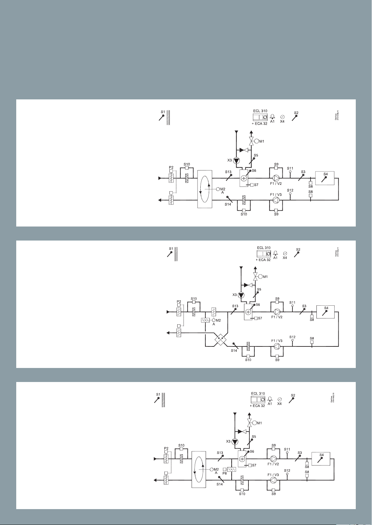
ECL Comfort 210/296/310 Application A214/A314
Multi purpose application. Temperature control of, for example, ventilation
systems with heating or cooling or a combination of these. Weather based
compensation, return temperature limitation, frost and re protection. Optional analog control of cross-ow or rotary heat exchanger.
Alarm function related to duct / ow temperature, re and frost.
A314.5
Example e
Ventilation system with heating, passive cooling (outside air) and room
temperature control. Analog controlled speed of fans in re lation to air
quality (CO2). Analog controlled valve
(M2) for heat recovery by means of a
Fluid battery. Control of Night damper P8 for reduced ventilation during
saving periods.
A314.6
Example a
Ventilation system with heating,
cooling and room temperature control. Analog controlled speed of fans
in relation to pressures. Analog controlled speed of rotary heat exchanger (M2) for heat recovery.
A314.6
Example b
Ventilation system with heating,
cooling and room temperature control. Analog controlled speed of fans
in relation to pressures. Analog controlled damper (M2) for heat recovery
by means of a cross heat exchanger.
28
28
A314.6
87H1469.10
Danfoss
S1
S2
A1 X4
P2
ECL 310
+ ECA 32
S10
S13
S14
X3
M1
S5
S6
S7
S10
S9
F1 / V2
S12
S3
S8
S8
S4
S9
F1 / V3
M3
S11
X5
P7
M2
A
Example c
Ventilation system with heating, cooling and room temperature control.
Analog controlled speed of fans in relation to pressures. Analog controlled
valve (M2) for heat recovery by means
of a Fluid battery.
S10
S10
ECL 310
+ ECA 32
S5
S6
S7
ECL 310
+ ECA 32
M1
S5
S6
S7
S2
A1 X4
M1
A1
M3
X5
X4
X5
S9
S3
F1 / V2
F1 / V3
S9
S2
M3
S9
F1 / V2
S11
F1 / V3
S9
S11
S8
S8
S3
S8
S8
87H1345.11
Danfoss
S4
87H1346.11
Danfoss
S4
29
29
29
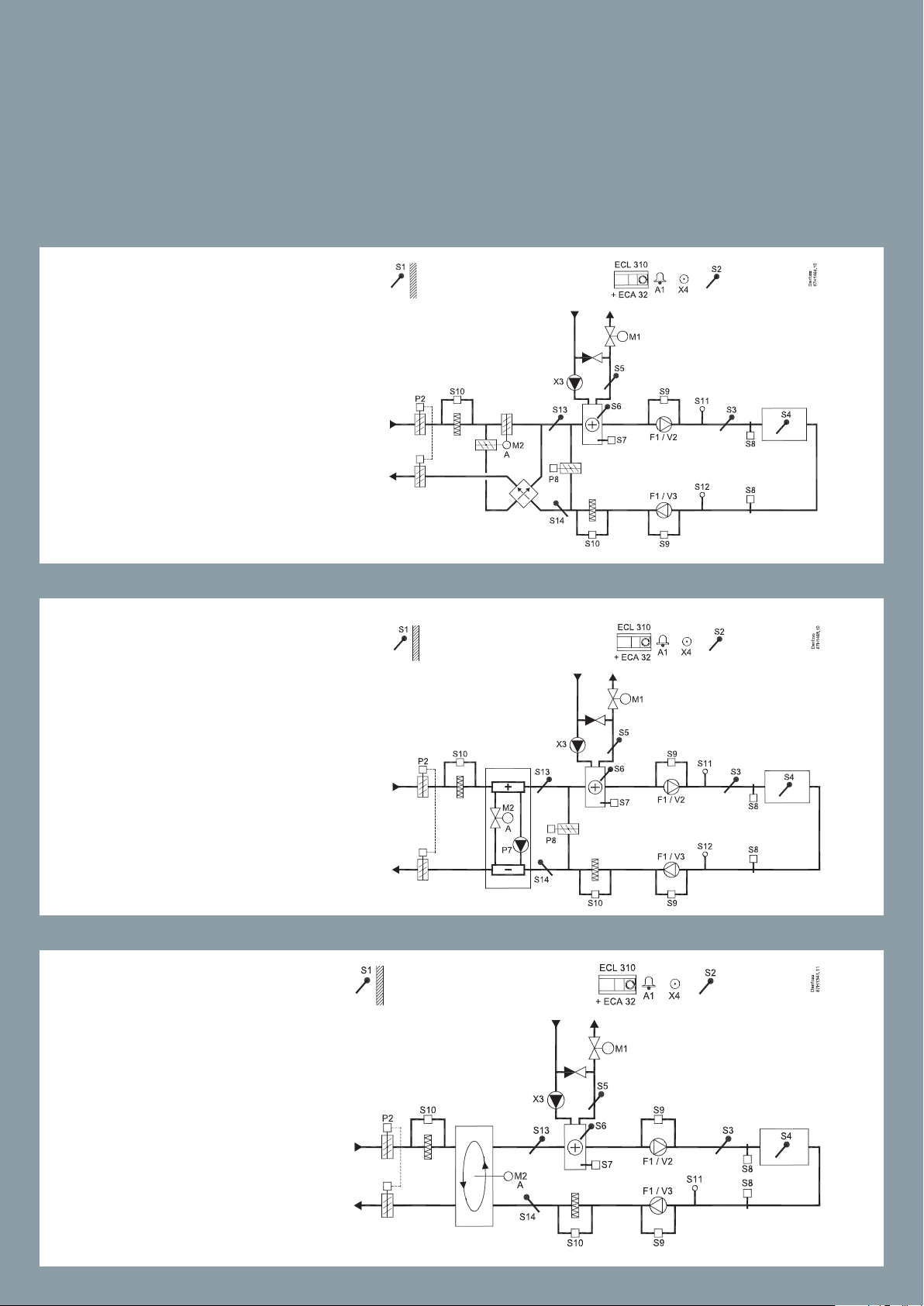
A314.7
Example a
Ventilation system with heating, cool-
S1
S10
P2
X3
S13
ing and room temperature control.
Analog con trolled speed of fans in re-
M2
A
lation to air quality (CO2). Analog controlled speed of rotary heat exchanger
S14
(M2) for heat recovery.
S1
A314.7
S10
P2
X3
S13
M2
A
S14
Example b
Ventilation system with heating, cooling and room temperature control.
Analog con trolled speed of fans in relation to air quality (CO2). Analog controlled damper (M2) for heat recovery
by means of a cross heat exchanger.
87H1471.11
Danfoss
S1
S2
A1
X4
M2
ECL 310
+ ECA 32
S10
X3
M1
S5
S6
S7
S10
S9
F1 / V2
S11
S3
S8
S8
S4
S9
F1 / V3
A
P2
S1
ECL 310
S9
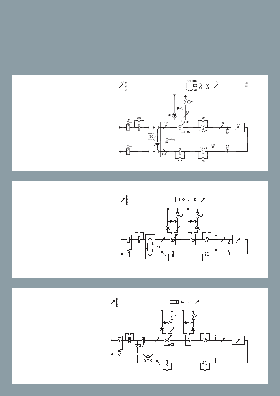
ECL Comfort 210/296/310 Application A214/A314
Multi purpose application. Temperature control of, for example, ventilation
systems with heating or cooling or a combination of these. Weather based
compensation, return temperature limitation, frost and re protection. Optional analog control of cross-ow or rotary heat exchanger.
Alarm function related to duct / ow temperature, re and frost.
A314.7
Example c
Ventilation system with heating, cooling and room temperature control.
Analog con trolled speed of fans in relation to air quality (CO2). Analog controlled valve (M2) for heat recovery by
means of a Fluid battery.
A314.9
S10
ECL 310
+ ECA 32
M1
S5
S6
S7
S2
A1
X4
M3
X5
S9
F1 / V2
F1 / V3
S9
S11
S3
S8
S8
87H1470.10
Danfoss
S4
S1
S10
P2
X3
S13
M2
A
P7
S14
Example a
Ventilation system with heating and
room temperature control. Analog
controlled speed of fans in relation to
air quality (CO2).
S2
87H1472.11
X4
A314.9
Example b
Ventilation system with heating and
room temperature control. Analog
con trolled speed of fans in re lation to
air quality (CO2). ON-OFF control of
damper P2.
30
30
M2
X3
A
S10
P2
+ ECA 32
S6
S10
A1
M1
S5
S9
S3
F1 / V2
S7
F1 / V3
S11
S8
S8
Danfoss
S4
S1
87H2068.13
87H2069.13
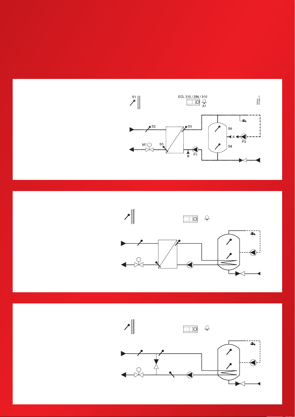
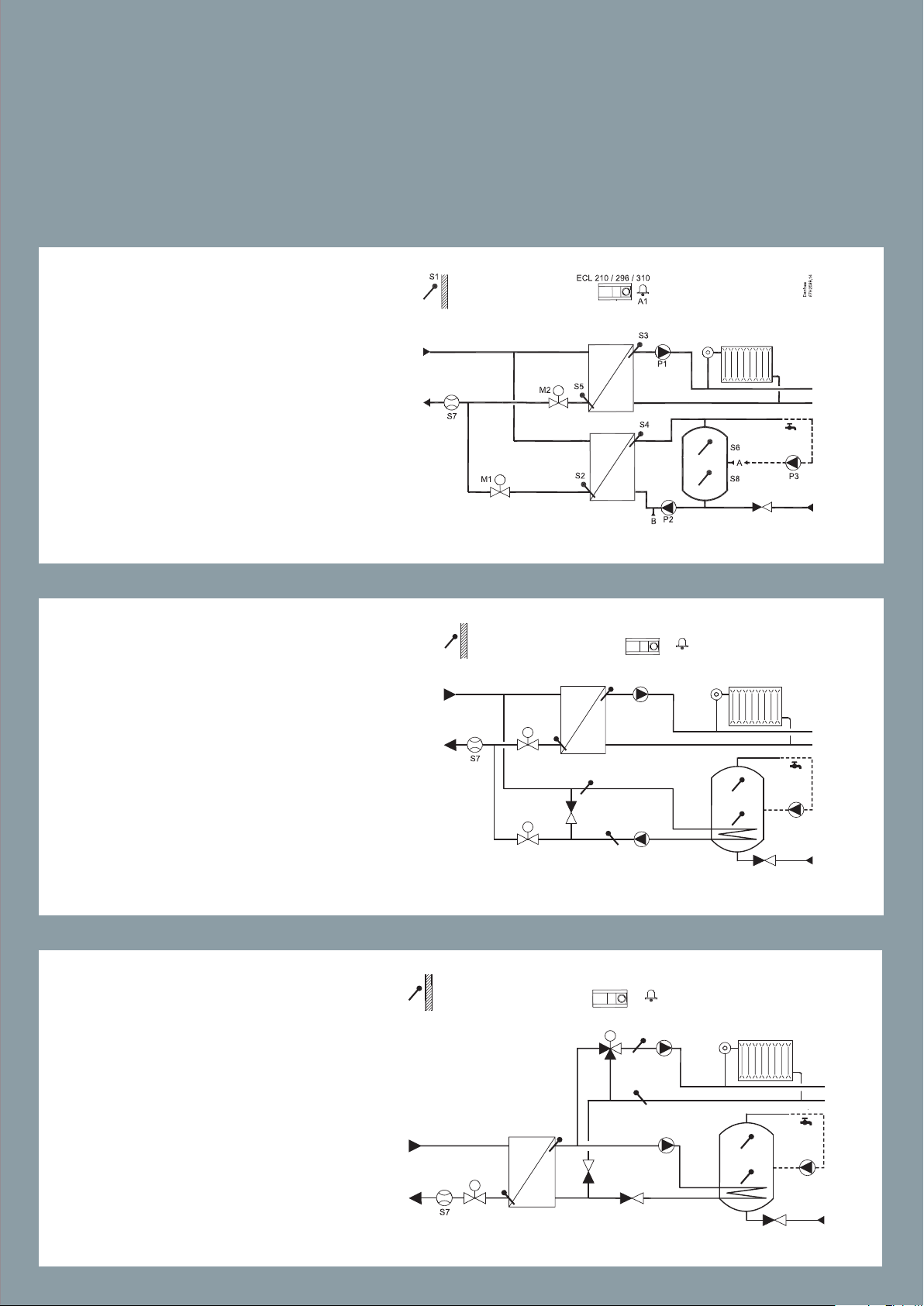
ECL Comfort 210/296/310 Application A217/A317
Advanced temperature control of DHW circuit with storage tank, directly heated or charging system. Return temperature limitation. Optional temperature
control of DHW heating temperature.
Alarm function related to ow temperature.
A217.1 / A317.1
Example a
Indirectly connected DHW charging system. DHW circulation through
DHW tank (A) or heat exchanger (B).
A217.1 / A317.1
Example b
Indirectly connected DHW heating
system.
A217.1 / A317.1
S1
M1
M1
ECL 210 / 296 / 310
A1
S2
S5
S2
S3
S3
P1
ECL 210 / 296 / 310
S5
S6
S8
A1
S6
S8
Danfoss
P3
Danfoss
P3
Example c
Directly connected DHW heating
system.
P1
31
31

S1
87H2071.13
ECL 210 / 296 / 310
S1
ECL 210 / 296 / 310
ECL Comfort 210 Application A217
Advanced temperature control of DHW circuit with storage tank, directly heated or charging system. Return temperature limitation. Optional temperature
control of DHW heating temperature.
Alarm function related to ow temperature.
A217.1 / A317.1
Example d
Directly connected DHW heating
system.
A217.2 / A317.2
Example a
Indirectly connected DHW charging
system with controlled heating temperature. DHW circulation through
DHW tank (A) or heat exchanger (B).
A217.2 / A317.2
Example b
Indirectly connected DHW charging
system with controlled heating temperature. DHW circulation through
DHW tank (A) or heat exchanger (B).
S2 S3
M1
M1
S2 S3
S5
S5
P1
P1
S4
P3
P3
Danfoss
Danfoss
87H2072.13
A1
S4
B
P2
A1
B
P2
S6
A
S8
S6
A
S8
32
32

A217. 3
Example a
Indirectly connected DHW heating
system. DHW circulation through heat
exchanger.
A217. 3
Example b
Indirectly connected DHW heating
system. DHW heating on demand via
ow switch (S8).
33
33

ECL Comfort 210 Application A217
Advanced temperature control of DHW circuit with storage tank, directly heated or charging system. Return temperature limitation. Optional temperature
control of DHW heating temperature.
Alarm function related to ow temperature.
A217. 3
Example c
Indirectly connected DHW heating
system. DHW circulation through
heat exchanger.
A217. 3
Example d
Directly heated DHW tank. DHW
circulation through DHW tank.
34
34

ECL Comfort 210/296/310 Application A230
Heating – Application A230.1
Weather compensated control of ow temperature in a heating circuit. Room
temperature and wind speed compensation. Sliding return temperature limitation. Alarm function related to ow temperature.
A230.1
Example a
Indirectly connected heating system
(typically district heating).
A230.1
Example b
Directly connected heating system.
A230.1
Example c
Boiler heating system with 3–port
valve.
35
35

ECL Comfort 210/296/310 Application A230
Cooling – Application A230.2
Control of ow temperature in a cooling circuit. Room and weather compensation. Return
temperature limitation.
A230.1
Example d
Boiler heating system with 4–port rotary valve.
A230.2
Example a
Indirectly connected cooling system
(typically district cooling).
A230.2
Example b
Directly connected cooling system.
36
36

A230.2
Example c
Indirectly connected cooling system,
constant ow on cooling supply side.
A230.2
Example d
Two circulation pumps in shifted
control, controlled by schedule 2.
37
37

ECL Comfort 210/296/310 Application A230
Heating – Application A230.4
Weather compensated control of ow temperature in a heating circuit. Room temperature compensation. Sliding return
temperature limitation. Power / ow limitation. Alarm function related to ow temperature.
Monitoring of temperatures in self-acting controlled DHW circuit.
A230.4
Example a
Indirectly connected heating system
(tipically district heating). Monitoring
of pressure and DHW temperatures.
A230.4
Example b
Indirectly connected heating system
(tipically district heating). Monitoring
of pressure and DHW temperatures.
Scheduled DHW circulation.
A230.4
Example c
Directly connected heating system
(tipically district heating). Monitoring
of pressure and DHW temperatures.
38
38

A230.4
Example d
Directly connected heating system
(tipically district heating). Monitoring
of pressure and DHW temperatures.
39

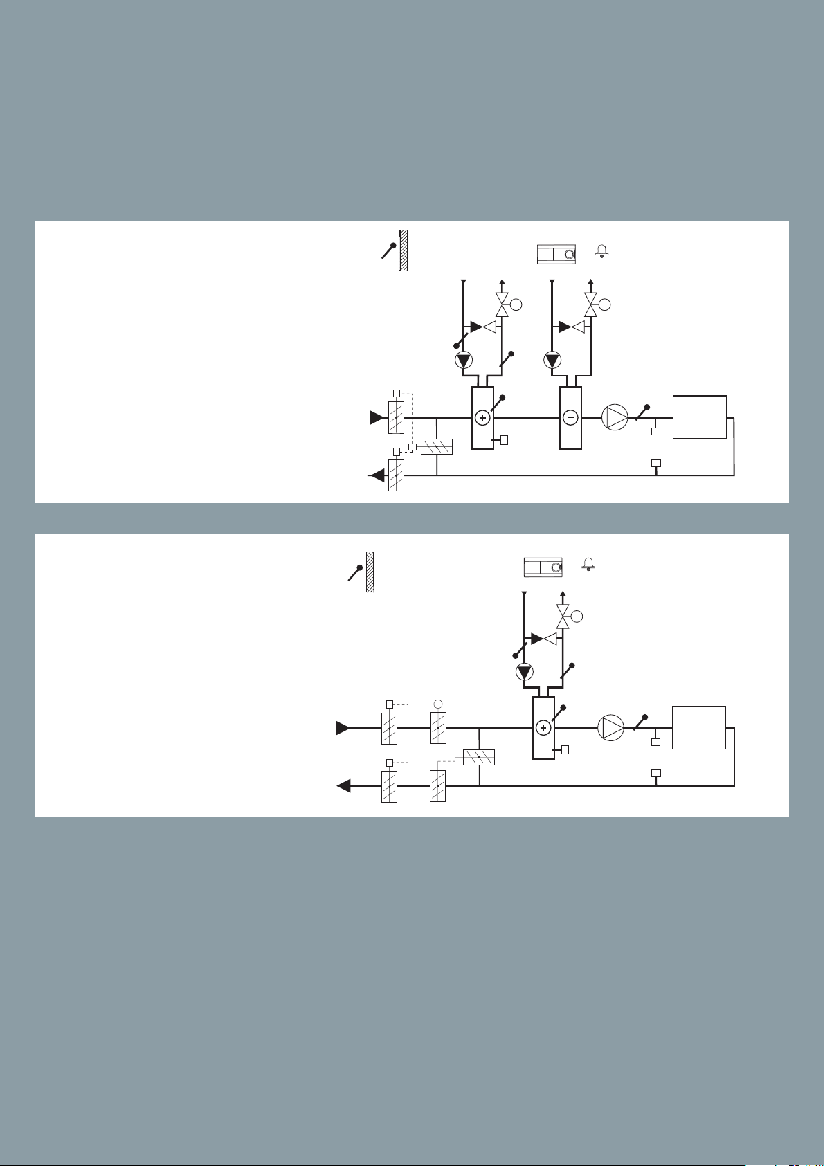
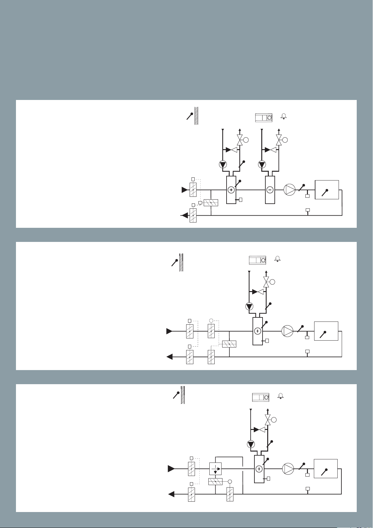
ECL Comfort 210/296/310 Application A231/A331
Weather compensated control of ow temperature in a heating circuit. Sliding return
temperature limitation. Control of one or two circulation pumps. Optional control of
ow temperature related to supply temperature. Rell water function.
Alarm function related to ow temperature, pressure and circulation pumps operation.
Additional function in A331: Control of one or two pumps for rell water function.
A231.1
Example a
Indirectly connected heating system
with two-pump control and rell water function.
A231.2
Example a
Indirectly connected heating system
with two-pump control and rell
water function (supply temperature
measurement gives further control /
limitation possibilities).
40
40
40

A331.1
Example a
Indirectly connected heating system with two-pump control and
rell water function.
A331.2
Example a
Indirectly connected heating system
with two-pump control and rell
water function (supply temperature
measurement gives further control /
limitation possibilities).
41
41

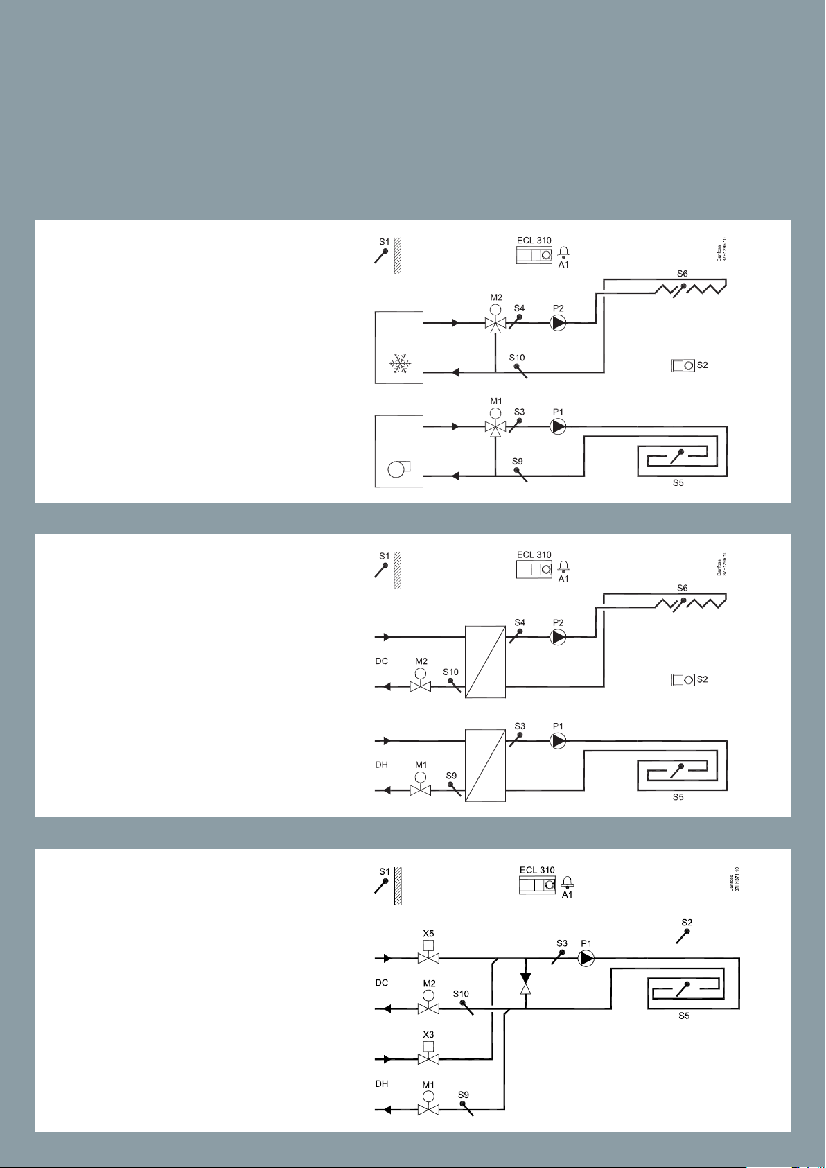
ECL Comfort 210/296/310 Application A232/A332
Weather compensated ow temperature control of heating / cooling circuit(s). Automatic change-over between heating and cooling. Circulation pump control. Dew point
(cooling mode only) and surface temperature compensation. Return temperature limitation.
A232.1
Example a
Control of ow temperature (heating
in oor / cooling in ceiling) in relation
to outdoor, room and dew point temperature.
A232.1
Example b
Control of ow temperature (heating /
cooling) in oor in relation to outdoor,
room and dew point temperature.
A232.1
Example c
Control of ow temperature (heating /
cooling) to a fan-coil in relation to outdoor, room and dew point temperature.
42
42

A232.1
Example d
Control of ow temperature (heating /
cooling) to a fan-coil in relation to outdoor, room and dew point temperature. Heating source: District heating.
Cooling source: Cooling machine.
A232.1
Example e
Control of ow temperature (heating /
cooling) in relation to outdoor, room
and dew point temperature. Heating /
cooling sources: District heating / district cooling.
A332.1
Example a
Control of ow temperature (heating
in oor / cooling in ceiling) in relation
to outdoor, room and dew point temperature. Optional return temperature limitation.
43
43
ECL Comfort 210/296/310 Application A232/A332
Weather compensated ow temperature control of heating / cooling circuit(s). Automatic change-over between heating and cooling. Circulation pump control. Dew point
(cooling mode only) and surface temperature compensation. Return temperature limitation.
A332.2
Example a
Separated control of ow temperatures for heating / cooling in
relation to outdoor, room and dew
point temperature. Optional return temperature limitations.
A332.2
Example b
District heating / cooling based
control of ow temperatures for
heating / cooling in relation to
outdoor, room and dew point
temperature. Optional return temperature limitations.
A332.2
Example c
Direct connected heating / cooling based control of ow temperatures for common heating / cooling circuit. Control in relation to
outdoor and room temperature.
Optional surface and return temperature limitations.
44
44

A332.2
Example d
Indirect connected heating / cooling based control of ow temperatures for common heating / cooling circuit. Control in relation to
outdoor and room temperature.
Optional sur face and return temperature limi tations.
A332.3
Example a
Separated control of ow temperatures in heating and cooling
circuits. Control in relation to outdoor and / or room temperature.
Optional sur face and return temperature limi tations.
Indirectly connected DHW system
with ow switch for DHW heating
on demand.
45
45
45

ECL 310
ECL Comfort 210/296/310 Application A232/A332
Weather compensated ow temperature control of heating / cooling circuit(s). Automatic change-over between heating and cooling. Circulation pump control. Dew
point (cooling mode only) and surface temperature compensation. Return temperature limitation.
A332.3
Example b
Separated control of ow temperatures in heating and cooling circuits.
Control in relation to outdoor and /
or room temperature. Optional surface and return temperature limitations.
Indirectly connected DHW system
with ow switch for DHW heating on
demand.
A332.4
Example a
Control of ow temperature (heating
in oor / cooling in ceiling) in relation
to outdoor, room and dew point temperature. Optional return and surface
temperature limitation. Override
functionalities for heating and cooling modes.
A1
M1
S3
P1
X3
X2
S10
M2
S8
S7
S9
S5
DanfossS187H1496.10
S6
S2
46
46

ECL Comfort 210/296/310 Application A237/A337
Weather compensated control of ow temperature in heating circuit. Room temperature compensation and sliding return temperature limitation.
Temperature control in DHW circuit with storage tank, directly heated or charging system. Return temperature limitation. Possibility for DHW priority.
Alarm function related to ow temperatures.
A237.1 / A337.1
Example a
Indirectly connected system and secondarily connected DHW tank with internal heat exchanger (optional DHW
priority).
A237.1 / A337.1
Example b
Indirectly connected system and secondarily connected DHW tank with internal heat exchanger (DHW priority).
A237.1 / A337.1
Example c
Indirectly connected system and
primarily connected DHW tank with
internal heat exchanger (optional
DHW priority).
47
47

ECL Comfort 210/296/310 Application A237/A337
Weather compensated control of ow temperature in heating circuit. Room temperature compensation and sliding return temperature limitation.
Temperature control in DHW circuit with storage tank, directly heated or charging system. Return temperature limitation. Possibility for DHW priority.
Alarm function related to ow temperatures.
A237.1 / A337.1
Example d
Directly connected system and
DHW tank with internal heat exchanger (optional DHW priority).
A237.2 / A337.2
Example a
Indirectly connected system and secondarily connected DHW charging
system (optional DHW priority).
A237.2 / A337.2
Example b
Indirectly connected system and secondarily connected DHW charging
system (DHW priority).
48
48
87H2053.15
S1
ECL 210 / 296 / 310
ECL Comfort 210/296/310 Application A247/A347
Weather compensated control of ow temperature in heating circuit. Room temperature compensation and sliding return temperature limitation.
Temperature control in DHW circuit with storage tank, directly heated or charging system. Return temperature limitation. Possibility for sliding DHW priority.
Alarm function related to ow temperatures.
A247.1
Example a
Indirectly connected heating system
and DHW charging system (optional
DHW priority).
Room temperature can be achieved
by an ECA 30.
A247.1
S1
M2
S5
ECL 210 / 296 / 310
S3
P1
A1
Danfoss
Example b
Indirectly connected heating system
and directly connected DHW tank
heating system. (Pre-controlled circuit
M1
and optional DHW priority).
Room temperature can be achieved
by an ECA 30.
A247.1
S4
S2
P2
A1
M2
S3
P1
S5
S6
S8
P3
Danfoss
87H2054.15
Example c
Indirectly connected heating and
DHW system (optional DHW priority).
Room temperature can be achieved
by an ECA 30.
49
S4
M1
S2
P2
S6
S8
P3
49
49

S1
87H2055.15
ECL 210 / 296 / 310
S1
87H2056.15
ECL 210 / 296 / 310
ECL Comfort 210/296/310 Application A247/A347
Weather compensated control of ow temperature in heating circuit. Room temperature compensation and sliding return temperature limitation.
Temperature control in DHW circuit with storage tank, directly heated or charging system. Return temperature limitation. Possibility for sliding DHW priority.
Alarm function related to ow temperatures.
A247. 2
Example a
Indirectly connected heating system
and DHW tank charging system with
pre-controlled charging temperature.
Room temperature can be achieved
by an ECA 30.
A247. 2
Danfoss
P1
S5
Example b
Indirectly connected heating system and DHW system. The DHW
tank charging has pre-controlled
charging temperature.
Room temperature can be achieved
by an ECA 30.
S3
M2
S2
M1
S4
P2
B
P4
S6
A
P3
S8
Danfoss
A247. 2
M2
S3
Example c
Indirectly connected heating system
S4
S5
and DHW system. The DHW tank
charging has pre-controlled charging
temperature. Optional DHW priority.
M1
S2
P2
Room temperature can be achieved
by an ECA 30.
P1
S6
A
P3
S8
B
P4
50
50
50

A247. 3
S1
87H1394.12
ECL 210 / 296 / 310
S1
87H1395.11
ECL 210 / 296 / 310
Example a
Indirectly connected heating system
and DHW charging system. The DHW
tank charging system has controlled
heating and charging temperature
and optional DHW priority.
Room temperature can be achieved
by an ECA 30.
A247. 3
Example b
Indirectly connected heating and
DHW charging system. The DHW tank
charging has controlled heating and
charging temperature and optional
DHW priority.
Room temperature can be achieved
P1
S5
S3
M2
S2
M1
S4
P2
S7
B
P4
S6
A
S8
Danfoss
P3
by an ECA 30.
A247. 3
M2
S3
P1
S5
Danfoss
Example c
Indirectly connected heating and
DHW charging system. The DHW tank
charging has optional DHW priority.
Room temperature can be achieved
by an ECA 30.
51
S4
M1
S2
P2
S7
B
P4
S6
A
P3
S8
51
51

87H2057.11
S7
S1
87H1474.10
ECL 310
S7
ECL Comfort 210/296/310 Application A247/A347
Weather compensated control of ow temperature in heating circuit. Room temperature compensation and sliding return temperature limitation.
Temperature control in DHW circuit with storage tank, directly heated or charging system. Return temperature limitation. Possibility for sliding DHW priority.
Alarm function related to ow temperatures.
A347.1
Example a
Indirectly connected heating system
and DHW charging system (optional
DHW priority).
A347.1
S1
M2
S5
M1
S2
S1
M2
S5
ECL 310
A1
S3
P1
S4
B
P2
ECL 310
A1
S3
P1
S6
A
S8
Danfoss
P3
S7
Danfoss
87H1473.10
Example b
S4
S6
Indirectly connected and controlled
heating sys tem. Controlled heating
temperature for DHW tank and optional DHW priority.
A347.1
Example c
Indirectly connected and controlled
heating sys tem. Controlled heating
M1
M1
S2
S2
P2
A1
M2
S3
P1
S5
S4
P2
S8
P3
Danfoss
S6
S8
P3
temperature for DHW tank and optional DHW priority.
52
52
52

A347. 2
S1
87H1475.11
ECL 310
S7
Example a
Indirectly connected heating system
and DHW system. The DHW tank
charging has direct connected and
pre-controlled charging temperature. Optional DHW priority.
A347. 2
Example b
Indirectly connected heating system
and DHW system. The DHW tank
charging has pre-controlled charging
A1
P1
S5
S3
M2
S2
M1
S4
P2
S9
B
P4
S6
A
S8
Danfoss
P3
temperature.
53
53

S1
87H1476.11
ECL 310
S7
S7
ECL Comfort 210/296/310 Application A247/A347
Weather compensated control of ow temperature in heating circuit. Room temperature compensation and sliding return temperature limitation.
Temperature control in DHW circuit with storage tank, directly heated or charging system. Return temperature limitation. Possibility for sliding DHW priority.
Alarm function related to ow temperatures.
A347. 2
Example c
Indirectly connected heating system
and DHW system. The DHW tank
charging has pre-controlled charging
temperature. Optional DHW priority.
A347. 3
A1
M2
S3
P1
S5
S4
M1
S2
S1
M2
P2
S3
S5
ECL 310
P1
S9
B
P4
A1
S6
A
S8
Danfoss
P3
Danfoss
87H1517.10
Example a
Indirectly connected heating system
and DHW charging system (optional
DHW priority).
S8 monitors DHW circulation return.
M1
S2
S4
B
P2
S6
S8
A
S8
P3
54
54

ECL Comfort 210/296/310 Application A260
Weather compensated control of ow temperature in two heating circuits.
Room temperature compensation and sliding return temperature limitation.
Circuits independent in parallel or circuit 2 after circuit 1.
Alarm function related to ow temperatures.
A260.1
Example a
Indirectly connected heating systems
(typically district heating). Circuit 2 is
oor heating.
A260.1
Example b
Indirectly connected heating systems
(typically district heating).
S7 is pulse based ow or energy meter.
A260.1
Example c
Indirectly connected heating systems
(typically district heating).
S7 is pulse based ow or energy meter.
55
55

ECL Comfort 210/296/310 Application A260
Weather compensated control of ow temperature in two heating circuits.
Room temperature compensation and sliding return temperature limitation.
Circuits independent in parallel or circuit 2 after circuit 1.
Alarm function related to ow temperatures.
A260.1
Example d
Indirectly connected heating systems
(typically district heating). Circuit 2 (as
sub-circuit) is oor heating.
A260.1
Example e
Directly connected heating systems
(boiler-based). Circuit 2 is oor heating.
A260.1
Example f
Directly connected heating systems
(boiler-based).
56
56

ECL Comfort 210/296/310 Application A266
Weather compensated control of ow temperature in heating circuit. Room temperature compensation and sliding return temperature limitation.
Flow temperature control in DHW circuit. Return temperature limitation. Sliding
DHW priority possibility. Optional DHW temperature control related to DHW ow
detection.
Alarm function related to ow temperatures.
A266.1
Example a
Indirectly connected heating and DHW
system (typically district heating).
S7 is pulse based ow or energy meter.
A266.1
Example b
Directly connected heating and
indirectly connected DHW system.
S7 is pulse based ow or energy meter.
A266.1
S1
M2
ECL 210 / 296 / 310
S5
S2
A1
S3
P2
Danfoss
87H2144.14
Example c
Indirectly connected heating system and
directly connected DHW tank heating.
S7 is pulse based ow or energy meter.
S7
S4
M1
S6
P1
57
57

ECL Comfort 210/296/310 Application A266
Weather compensated control of ow temperature in heating circuit. Room temperature compensation and sliding return temperature limitation.
Flow temperature control in DHW circuit. Return temperature limitation. Sliding
DHW priority possibility. Optional DHW temperature control related to DHW ow
detection.
Alarm function related to ow temperatures.
A266.2
Example a
Indirectly connected heating and DHW
system with ow switch.
S7 is pulse based ow or energy meter
A266.9
Example a
Indirectly connected heating and DHW
system with pressure transmitter and
universal alarm switch.
A266.10
Example a
Indirectly connected heating and DHW
system.
Secondary side return temperatures
monitoring and universal alarm switch.
S7 is pulse based ow or energy meter.
Flow / energy limitation is optional.
58
58
58

ECL 210 / 296 / 310
S1
ECL 210 / 296 / 310
S1
87H2165.12
ECL 210 / 296 / 310
S1
ECL Comfort 210/296/310 Application A275/A375
Weather compensated flow temperature control of 1-stage boiler based heating systems. One direct heating circuit and one mixing circuit. Circulation pumps control, room temperature control and sliding return
temperature limitation.
Temperature control of DHW storage tank with internal heat exchanger. Frost protection and alarm function.
The A275 application key contains applications related to ECL Comfort 310 for increased functionalities (multiple boiler stages).
A275.1
Danfoss
A1
S3
S7
87H2163.13
Example a
Boiler ON / OFF control for a heating
circuit.
* = Automatic by-pass valve.
A275.1
Example b
Boiler ON/OFF control for a heating circuit. The boiler circuit is
equipped with a low loss header.
* = Automatic by-pass valve.
P1
S5
B1
S3
P1
S5
B1
*
A1
*
1
Danfoss
87H2164.12
S7
1
A1
A275.2
S3
P1
S5
B1
*
Danfoss
S7
1
Example a
Boiler ON / OFF control for a heating
and a DHW circuit. Optional DHW
priority.
* = Automatic by-pass valve.
P3
S6
2
59
59

87H2166.12
ECL 210 / 296 / 310
87H2168.12
ECL 210 / 296 / 310
S1
87H2167.12
ECL 210 / 296 / 310
S1
ECL Comfort 210/296/310 Application A275/A375
Weather compensated flow temperature control of 1-stage boiler based heating systems. One direct heating circuit and one mixing circuit. Circulation pumps control, room temperature control and sliding return
temperature limitation.
Temperature control of DHW storage tank with internal heat exchanger. Frost protection and alarm function.
The A275 application key contains applications related to ECL Comfort 310 for increased functionalities (multiple boiler stages).
S1
Danfoss
S7
1
A275.2
A1
S3
P1
S5
B1
*
Example b
Boiler ON / OFF control for a heating and a DHW circuit. DHW priority.
* = Automatic by-pass valve.
A275.2
Example c
Boiler ON / OFF control for a heating
and a DHW circuit. Optional DHW priority. The boiler circuit is equipped
with a low loss header.
* = Automatic by-pass valve.
P3/M1
A1
S3
P1
*
S5
B1
P3
S6
2
Danfoss
S7
1
S6
2
A1
A275.2
Example d
S3
P1
S5
B1
*
Danfoss
S7
1
Boiler ON / OFF control for a heating and a DHW circuit. DHW
priority. The boiler circuit is
equipped with a low loss header.
P3/M1
S6
2
* = Automatic by-pass valve.
60
60

A275.3
87H2169.13
ECL 210 / 296 / 310
87H2170.13
ECL 210 / 296 / 310
S1
87H2171.13
ECL 210 / 296 / 310
S1
Example a
I Boiler ON / OFF control for a direct
heating circuit (1), a mixing circuit (2)
and a DHW circuit (3). Optional DHW
priority.
* = Automatic by-pass valve.
A275.3
Example b
Boiler ON / OFF control for a direct
heating circuit (1), a mixing circuit
(2) and a DHW circuit (3). Partly DHW
priority.
* = Automatic by-pass valve.
S1
M2
S4
P4
S3
S5
B1
S3
P1
S5
B1
P3/M1
S2
P1
*
S6
P3
M2
S4
P4
S2
*
S6
Danfoss
S8
2
S7
1
3
Danfoss
S8
2
S7
1
3
Danfoss
A275.3
Example c
S3
S5
B1
Boiler ON / OFF control for a direct
heating circuit (1), a mixing circuit (2)
and a DHW circuit (3). DHW priority.
P1
P3/M1
M2
S4
P4
S2
*
S8
2
S7
1
S6
3
* = Automatic by-pass valve.
61
61

87H2172.13
ECL 210 / 296 / 310
S1
87H2173.13
ECL 210 / 296 / 310
S1
87H2174.13
ECL Comfort 210/296/310 Application A275/A375
Weather compensated flow temperature control of 1-stage boiler based heating systems. One direct heating circuit and one mixing circuit. Circulation pumps control, room temperature control and sliding return
temperature limitation.
Temperature control of DHW storage tank with internal heat exchanger. Frost protection and alarm function.
The A275 application key contains applications related to ECL Comfort 310 for increased functionalities (multiple boiler stages).
Danfoss
A275.3
Example d
Boiler ON / OFF control for a direct
heating circuit (1), a mixing circuit (2)
and a DHW circuit (3). Optional DHW
priority. The mixing circuit (2) is controlled by means of a 4-port mixing
valve.
* = Automatic by-pass valve.
S3
S5
B1
S4
M2
P4
S2
P1
*
P3
S8
2
S7
1
S6
3
Danfoss
A275.3
Example e
Boiler ON / OFF control for a direct
heating circuit (1), a mixing circuit (2)
and a DHW circuit (3). Optional DHW
priority. The boiler circuit is equipped
S3
S5
B1
M2
S4
P4
S2
P1
*
S8
2
S7
1
S6
3
with a low loss header.
* = Automatic by-pass valve.
S1
ECL 210 / 296 / 310
P3
Danfoss
A275.3
S3
S5
M2
S4
P4
S2
S8
2
Example f
Boiler ON / OFF control, a mixing circuit control and a DHW circuit control. Optional DHW priority.
* = Automatic by-pass valve.
62
62
B1
S6
3
P3

A275.3
87H2175.13
ECL 210 / 296 / 310
S1
87H2176.10
ECL 310
S1
①
B1
87H2178.10
ECL 310
S1
①
Danfoss
M2
S4
S8
Example g
Boiler ON / OFF control for a direct
heating circuit (1) and a mixing circuit
(2).
* = Automatic by-pass valve.
A375.1
Example a
One boiler with 2 x burner ON / OFF
control for a heating circuit.
* = Automatic by-pass valve.
P4
S2
S3
P1
S5
B1
S3
B2
S5
P1
*
A1
*
2
S7
1
Danfoss
S7
A375.1
Example b
B1
B2
2 x boiler ON / OFF control for a heat-
S3
S5
A1
P1
*
ing circuit.
* = Automatic by-pass valve.
Danfoss
S7
63
63

ECL 310
①
87H2177.10
ECL 310
S1
①
87H2180.10
ECL 310
S1
①
ECL Comfort 210/296/310 Application A275/A375
Weather compensated flow temperature control of 1-stage boiler based heating systems. One direct heating circuit and one mixing circuit. Circulation pumps control, room temperature control and sliding return
temperature limitation.
Temperature control of DHW storage tank with internal heat exchanger. Frost protection and alarm function.
The A275 application key contains applications related to ECL Comfort 310 for increased functionalities (multiple boiler stages).
A375.1
S1
Danfoss
87H2179.10
S7
Example c
One boiler with 2 x burner ON / OFF
control for a heating circuit. The boiler circuit is equipped with a low loss
header.
* = Automatic by-pass valve.
A1
S3
P1
B2
S5
B1
*
A375.1
Example d
2 x boiler ON / OFF control for a heating
circuit. The boiler circuit is equipped
with a low loss header.
* = Automatic by-pass valve.
A375.1
B1 B2
A1
S3
P1
S5
S3
*
A1
Danfoss
S7
Danfoss
Example e
Two boilers with 2 x burner ON / OFF
control for a heating circuit.
* = Automatic by-pass valve.
64
64
B2
B1
B4
B3
S5
P1
*
S7

A375.1
87H2181.10
ECL 310
S1
①
87H2182.10
S1
①
ECL 310
87H2186.10
S1
①
ECL 310
Example f
Up to 4 x boiler ON / OFF control for a
heating circuit.
* = Automatic by-pass valve.
A375.1
Example g
Up to 8 x boiler ON / OFF control for a
heating circuit.
* = Automatic by-pass valve.
B1 B4
B1 B8
S3
S5
S3
S5
+ ECA 32
A1
P1
P1
*
A1
*
Danfoss
S7
Danfoss
S7
A375.1
+ ECA 32
S3
Example h
Up to 8 x boiler ON / OFF control for
a heating circuit. The rst boiler (high
B1
B2
B8
S5
A1
P1
*
eciency) has highest priority.
* = Automatic by-pass valve.
Danfoss
S7
65
65

87H2187.10
S1
①
ECL 310
87H2188.10
S1
ECL 310
87H2189.10
S1
ECL 310
②
①
③
ECL Comfort 210/296/310 Application A275/A375
Weather compensated flow temperature control of 1-stage boiler based heating systems. One direct heating circuit and one mixing circuit. Circulation pumps control, room temperature control and sliding return
temperature limitation.
Temperature control of DHW storage tank with internal heat exchanger. Frost protection and alarm function.
The A275 application key contains applications related to ECL Comfort 310 for increased functionalities (multiple boiler stages).
A375.1
Example i
Up to 8 x boiler ON / OFF control for
a heating circuit. The rst two boilers
(high eciency) have highest priority.
* = Automatic by-pass valve.
A375.2
B1
B2 B3
B1 B8
A1
+ ECA 32
S3
B8
S5
S3
S5
P1
+ ECA 32
*
A1
P1
*
Danfoss
S7
Danfoss
S7
①
Example a
Up to 8 x boiler ON / OFF control for a
heating circuit and a DHW circuit.
+ ECA 32
M2
P3
A1
S4
P4
S2
P1
*
* = Automatic by-pass valve.
A375.3
Example a
B1 B8
Up to 8 x boiler ON / OFF control for a
direct heating circuit (1), a mixing cir-
S3
S5
cuit (2) and a DHW circuit (3). Optional
S6
②
P4
Danfoss
S8
S7
S6
DHW priority.
* = Automatic by-pass valve.
66
66
P3

A375.4
Danfoss
87H1544.10
P1
S7
*
ECL 310
+ ECA 32
A1
S1
S3
S5
B1
1
S9
V1
Danfoss
87H1545.10
P1
S7
*
ECL 310
S1
S3
S5
B1
S6
P3
P4
S8
S2
S4
M2
+ ECA 32
A1
1
2
3
P5
S9
V1
Example a
Boiler ON / OFF or modulating control for a heating circuit. S9 measures
the static pressure.
* = Automatic by-pass valve.
A375.5
Example a
Boiler ON / OFF or modulating control for two heating circuits and one
DHW circuit. S9 measures the static
pressure.
* = Automatic by-pass valve.
67
67

ECL Comfort 310 Application A319
Weather compensated control of flow temperature in a heating circuit, based on an advanced buffer
temperature control. Charging pump P2 is speed controlled, based on 0 - 10 Volt or PWM signal. Discharging of
buffer is avoided according to built-in logic. Differential pressure (S9) can be maintained by means of speed controlled circulation pump P3 (0 - 10 Volt or PWM).
Optional sliding return temperature limitation.
Relay output (X1) for buffer heating demand; override signal (S10) for remote setting of desired flow temperature.
Alarm functions are related to flow temperatures.
A319.1
Example a
Indirectly connected charging system
with 2 temperature sensors in buer.
Heating system connected directly to
buer.
A319.2
Example a
Indirectly connected charging system
with 2 temperature sensors in buer.
Heating system connected to buer
via mixing valve.
68
68

ECL Comfort 310 Application A333
Weather compensated control of flow temperature in heating circuit. Sliding return
temperature limitation. Control of one or two circulation pumps. Refill water function for one or two pumps and refill water storage control.
Pressure and temperature monitoring functions.
Alarm function related to flow temperature, pressure and circulation pumps operation.
A333.1
Example a
Indirectly connected heating system
with control of two circulation pumps.
Rell water function with control of
two pumps.
A333.2
Example a
Indirectly connected heating system
with control of two circulation pumps
(ON / OFF and speed control). Rell
water function with control of two
pumps (ON / OFF and speed control).
Rell water storage control.
A333.3
Example a
Indirectly connected heating system
with control of two circulation pumps
(ON / OFF and speed control). 0 - 10 V
control of control valve M1. Rell water
function with control of two pumps
(ON / OFF and speed control). Rell
water storage control.
69
69

ECL Comfort 310 Application A361
87H2002.10
ECL 310
Weather compensated control of ow temperature in two heating circuits.
Sliding return temperature limitation. Control of one or two circulation pumps
in each heating circuit. Optional control of ow temperature related to supply
temperature. Rell water function.
Alarm function related to ow temperature, pressure and circulation pumps
operation.
A361.1
Example a
Indirectly connected heating systems with two-pump control and
rell water function.
A361.2
M1
M2
R6
S7
P
P1
S3
P2
S5
P4
S6
S10
V1
S4
V2
S8
P
P3
P5
S9
Danfoss
Example a
Indirectly connected heating systems
with two-pump control and rell
water function (supply temperature
measurement gives further control /
limitation possibilities).
70
70

ECL Comfort 310 Application A362
Danfoss
87H1755.10
S1
ECL 310
A1
+ ECA 32
V1
P5
S5
O2
S6
V2
O1
S2
V3 (0 - 10 V)
S10
S9
S7 S8 S15 S16
S3
S4
Danfoss
87H1754.10
S1
ECL 310
A1
+ ECA 32
V1
P1
S3
S5
O2
S4
S6
V2
P2
O1
S2
V3 (0 - 10 V)
S10
S9
S7
S8
S15
S16
Weather compensated control of flow temperature in a heating circuit, based on advanced cascade control of 2 heat
exchangers (HEX). Control valve characteristics are taken into consideration and flow in unused HEX circuit can be stopped.
Optional sliding return temperature limitation. Scheduled shift for inversed cascade (HEX-1 - HEX-2 and HEX-2 - HEX-1) can
be set. Override inputs for start of HEX-1 and HEX-2 are available. M-Bus based signal can be used for flow / energy
limitation.
Up to 6 heat exchangers can be cascade controlled by 1, 2 or 3 ECL Comfort 310 controllers, each equipped with the application key A362; the ECL controllers are interconnected by means of the ECL 485 Bus. Alarm functions are related to flow
and flow temperatures.
A362.1
Example a
Indirectly connected system with 2 x
HEX, each managed by means of a 0
- 10 Volt controlled motorized control
valve (MCV). Each HEX circuit has its
own circulation pump.
A362.1
Example b
Indirectly connected system with 2 x
HEX, each managed by means of a 0 10 Volt controlled MCV.
One circulation pump is common.
A362.1
Example c
Indirectly connected system with 2
x HEX, each managed by means of a
3-point controlled MCV with position
feedback.
Each HEX circuit has its own circulation
pump, but a common circulation pump
can be used.
S5
S6
ECL 310
+ ECA 32
A1
S3
P1
S9
S4
P2
S10
87H1756.10
Danfoss
71
71
S15 S16
V3 (0 - 10 V)
S2
S8
S7
O1
O2
S1
M1
S12 (0 - 10 V)
M2
S13 (0 - 10 V)

Danfoss
87H1757.10
S1
ECL 310
A1
+ ECA 32
V1
P1
S5
O2
S6
P2
O1
S2
V3 (0 - 10 V)
S10
S9
S7
S8
S15
S16
S12 (0 - 10 V)
M1
V2
S13 (0 - 10 V)
M2
S3
S4
ECL Comfort 310 Application A362
A362.1
Example d
Indirectly connected system with 2 x
HEX, each managed by means of one 0 10 Volt controlled MCV and one 3-point
controlled MCV with position feedback.
Each HEX circuit has its own circulation
pump, but a common circulation pump
can be used.
72
72

73
73

ECL Comfort 310 Application A367
S1
ECL 310
S1
ECL 310
S1
ECL 310
P2 / M3
Weather compensated control of ow temperature in two heating circuits. Room temperature compensation and sliding return temperature limitation. Heating circuits work independent in parallel or circuit 2 after circuit 1.
Temperature control in DHW circuit with storage tank, directly heated or charging system.
Return temperature limitation. DHW priority. Alarm function related to ow temperatures.
Danfoss
87H2073.11
S9
S7
A367.1
A1
S4
M2
S2
P5
Example a
Indirectly connected system with 2
heating circuits and secondarily connected DHW tank with internal heat
exchanger (optional DHW priority).
A367.1
Example b
Indirectly connected system with 2
heating circuits and secondarily connected DHW tank with internal heat
exchanger (DHW priority).
P1
S3
M1
S5
P2
A1
S4
M2
S2
S3
M1
S5
P5
P1
S6
S8
P3
Danfoss
87H2074.11
S9
S7
S6
S8
P3
Danfoss
A1
A367.1
S4
M2
S2
S3
M1
S5
P5
P1
87H2075.11
S9
S7
Example c
Indirectly connected system with 2
heating circuits and primarily connected DHW tank with internal heat
exchanger (optional DHW priority).
74
74
P2 / M3
S6
S8
P3
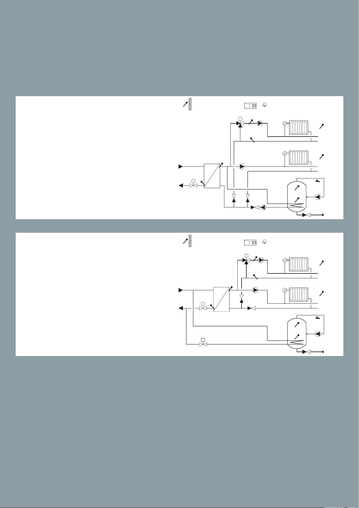
A367.1
S1
ECL 310
S1
ECL 310
Example d
Indirectly connected system with 2
heating circuits (one connected as sub
circuit) and secondarily connected
DHW tank with internal heat exchanger (optional DHW priority).
A367.1
Danfoss
M2
S3
M1
S5
P1
M2
A1
S4
P5
S2
P2
A1
S4
P5
S2
87H2076.11
S9
S7
S6
S8
P3
Danfoss
87H2077.11
S9
Example e
S3
M1
S5
P1
S7
Indirectly connected system with 2
heating circuits (one connected as sub
circuit) and primarily connected DHW
tank with internal heat exchanger (op-
P2 / M3
tional DHW priority).
S6
S8
P3
75
75

ECL Comfort 310 Application A367
S1
ECL 310
P2 / M3
S1
ECL 310
S1
ECL 310
Weather compensated control of ow temperature in two heating circuits. Room temperature compensation and sliding return temperature limitation. Heating circuits work independent in parallel or circuit 2 after circuit 1.
Temperature control in DHW circuit with storage tank, directly heated or charging system.
Return temperature limitation. DHW priority. Alarm function related to ow temperatures.
Danfoss
87H2078.11
(S7)
(S7)
A367. 2
A1
S4
M2
S2
P5
Example a
Indirectly connected system with 2
heating circuits and secondarily connected DHW charging system (optional DHW priority).
A367. 2
Example b
Indirectly connected system with 2
heating circuits and secondarily connected DHW charging system (DHW
priority).
P1
S3
M1
S5
P2
S4
M2
S2
S3
M1
S5
P1
P5
S9
P4
A1
S9
P4
S6
P3
S8
Danfoss
87H2079.11
(S7)
(S7)
S6
P3
S8
Danfoss
M2
A367. 2
Example c
Indirectly connected system with 2
heating circuits (one connected as
S3
M1
S5
P1
S4
S2
sub circuit) and secondarily connect-
A1
P5
S9
ed DHW charging system (optional
DHW priority).
76
76
P2
P4
87H2080.11
(S7)
(S7)
S6
P3
S8

ECL Comfort 310 Application A368
Weather compensated control of ow temperature in heating circuit. Sliding return temperature limitation. Control of one or two circulation pumps. Optional control of ow temperature
related to supply temperature. Rell water function for one or two pumps.
Flow temperature control in DHW circuit. Return temperature limitation. Sliding DHW priority
possibility. Control of one or two circulation pumps.
Alarm function related to ow temperature, pressure and circulation pumps operation.
A368.1
Example a
Indirectly connected heating and DHW
system with two-pump control and rell water function.
A368.2
Example a
Indirectly connected heating and
DHW system with two-pump control
and rell water function (supply temperature measurement gives further
control / limitation possibilities).
A368.3
Example a
Indirectly connected heating and DHW
system with two-pump control and
rell water function. Pressure measurements in the system.
77
77
77

ECL Comfort 310 Application A368
Weather compensated control of ow temperature in heating circuit. Sliding return temperature limitation. Control of one or two circulation pumps. Optional control of ow temperature
related to supply temperature. Rell water function for one or two pumps.
Flow temperature control in DHW circuit. Return temperature limitation. Sliding DHW priority
possibility. Control of one or two circulation pumps.
Alarm function related to ow temperature, pressure and circulation pumps operation.
A368.4
Example a
Indirectly connected heating and
DHW system with two-pump control
and rell water function. Supply temperature measurement gives further
control / limitation possibilities. Pressure measurements in the system.
A368.5
Example a
Indirectly connected heating and
DHW system with two circulation
pump control and rell water function with volume measurement.
Monitoring of secondary return temperatures. Monitoring of pressures.
A368.6
Example a
Indirectly connected heating and
DHW system with two circulation
pump control and rell water function. Monitoring of secondary return
temperatures. Monitoring of pressure
in heating circuit.
78
78
78

S1
87H2097.11
ECL 310
S1
ECL 310
S1
87H2099.11
ECL 310
ECL Comfort 310 Application A376
Weather compensated control of ow temperature in two heating circuits. Room temperature compensation and sliding return temperature limitation. Heating circuits work
independent in parallel or circuit 2 after circuit 1. Flow temperature control in DHW circuit.
Return temperature limitation. Sliding DHW priority possibility. Optional DHW temperature control related to DHW ow detection. Alarm functions related to ow temperatures,
pressures and extra alarm input. Optional control of motorized control valves by means of
analog signal (0-10 volt).
A376.1
Example a
Indirectly connected heating and DHW
system (typically district heating).
A376.1
A1
S3
M2
S5
M3
S10
M1
S6
S3
M2
S5
P2
S9
P3
S4
P1
A1
P2
Danfoss
S2
1
S7
2
3
Danfoss
87H2098.11
S2
1
M3
Example b
Indirectly connected heating and DHW
system (typically district heating).
S9
P3
S10
S4
S7
2
Heating circuit 2 is connected as a sub-circuit of heating circuit 1. Alternatively, heating circuit 2 can be a oor heating circuit.
A376.2
Example a
M1
S6
P1
A1
S3
M2
S5
M3
S10
S7
P2
S9
P3
S4
3
Danfoss
(S2)
1
(S2)
2
Indirectly connected heating and DHW
system with ow switch ((DHW heating on
demand).
M1
S6
S8
P1
3
79
79

ECL Comfort 310 Application A376
S1
ECL 310
S1
ECL 310
Weather compensated control of ow temperature in two heating circuits. Room temperature compensation and sliding return temperature limitation. Heating circuits
work independent in parallel or circuit 2 after circuit 1.
Flow temperature control in DHW circuit. Return temperature limitation. Sliding DHW
priority possibility. Optional DHW temperature control related to DHW ow detection.
Alarm functions related to ow temperatures, pressures and extra alarm input.
Optional control of motorized control valves by means of analog signal (0-10 volt).
A1
A376.2
Example b
Indirectly connected heating and
DHW system with ow switch (DHW
heating on demand). Heating circuit 2
is connected as a sub-circuit of heating circuit 1. Alternatively, heating circuit 2 can be a oor heating circuit.
M2
S5
S7
M1
S6
S3
P2
M3
S9
P3
S10
S4
S8
P1
(S2)
1
(S2)
2
3
Danfoss
87H2100.11
Danfoss
A1
A376.3
M2
S5
A
M3
S10
Example a
Indirectly connected heating and DHW
system (typically district heating). Motorized control valves are controlled by
means of analog signals (0–10 V).
A376.3
A
M1
S6
A
+ ECA 32
S3
P2
S9
P3
S4
P1
A1
87H2101.11
S2
1
S7
2
3
1
Example b
Indirectly connected heating and
DHW system (typically district heating). Motorized control valves are
controlled by means of analog signals
(0–10 V). Heating circuit 2 is connected
as a sub-circuit of heating circuit 1. Alternatively, heating circuit 2 can be a
oor heating circuit.
2
3
80
80

A376.4
S1
ECL 310
Danfoss
A1
S3
M2
S5
P2
S9
87H1430.11
S2
1
Example a
Indirectly connected system with 1
heating circuit, 1 directly DHW heating
circuit and 1 directly DHW heating circuit with ow switch (DHW heating on
demand).
A376.9
Example a
Indirectly connected heating and DHW
system with pressure transmitters and
alarm input (typically district heating).
M3
S10
S7
M1
S4
S6
S8
P3
P1
2
3
81
81
81

S1
87H2104.11
ECL 310
ECL Comfort 310 Application A376
Weather compensated control of ow temperature in two heating circuits. Room temperature compensation and sliding return temperature limitation. Heating circuits
work independent in parallel or circuit 2 after circuit 1.
Flow temperature control in DHW circuit. Return temperature limitation. Sliding DHW
priority possibility. Optional DHW temperature control related to DHW ow detection.
Alarm functions related to ow temperatures, pressures and extra alarm input.
Optional control of motorized control valves by means of analog signal (0-10 volt).
A376.9
Example b
Indirectly connected heating and
DHW system with pressure transmitters and alarm input (typically district
heating). Heating circuit 2 is connected as a sub-circuit of heating circuit 1.
Alternatively, heating circuit 2 can be a
oor heating circuit.
A376.10
S12
S15S8 S16
A1
+ ECA 32
S3
M2
S5
S11
S4
M1
(S6)
M3
S6
P2
S7
S2
S9
P3
S14
S10
P1
Danfoss
1
2
3
Example a
Indirectly connected heating and
DHW system with pressure transmitters and alarm input (typically district
heating). Monitoring of secondary return temperatures.
82
82

ECL Comfort 310 Application A377
S1
87H1521.10
ECL 310
S1
87H1522.10
ECL 310
S1
ECL 310
Weather compensated control of flow temperature in two heating circuits. Room
temperature compensation and sliding return temperature limitation. Heating circuits
work independent in parallel or circuit 2 after circuit 1.
Temperature control in DHW circuit with storage tank, directly heated or charging
system. Return temperature limitation. DHW priority. Optional temperature control of
DHW heating temperature.
Alarm function related to flow temperatures.
A377.1
Example a
Indirectly connected heating systems
and DHW charging system (optional
DHW priority).
A377.1
A1
S4
M3
S2
M2
S5
M1
S10
P5
S3
P2
S9
B
P4
M3
A1
S4
P5
S6
A
P3
S8
Danfoss
Danfoss
S2
S10
S3
P2
S9
B
P4
M3
S3
A1
S4
P5
S2
S6
A
P3
S8
Danfoss
87H2145.13
Example b
Indirectly connected heating systems
and DHW charging system (optional
DHW priority). Heating circuit 2 is connected as a sub-circuit of heating circuit 1. Alternatively, heating circuit 2
can be a oor heating circuit.
A377.1
M2
S5
M1
Example c
Indirectly connected heating systems
(S9)
P2
S6
A
P3
S8
B
P4
83
83
and DHW charging system with preheating circuit control and optional
DHW priority. Heating circuit 2 is connected as a sub-circuit of heating circuit 1. Alternatively, heating circuit 2
can be a oor heating circuit.
M2
S5
S9
M1
S10
P1

87H2141.12
ECL 310
ECL 310
S1
87H2143.12
ECL Comfort 310 Application A377
Weather compensated control of flow temperature in two heating circuits. Room temperature compensation and sliding return temperature limitation. Heating circuits work
independent in parallel or circuit 2 after circuit 1.
Temperature control in DHW circuit with storage tank, directly heated or charging system.
Return temperature limitation. DHW priority. Optional temperature control of DHW heating temperature.
Alarm function related to flow temperatures.
A377. 2
Example a
Indirectly connected heating systems
and DHW charging system (optional
DHW priority). Alternatively, heating
circuit 2 can be a oor heating circuit.
The DHW tank charging has adaptive
and pre-controlled charging temperature.
A377. 2
Example b
Indirectly connected heating systems
and DHW charging system (optional
DHW priority). Heating circuit 2 is
connected as a sub-circuit of heating
circuit 1. Alternatively, heating circuit
2 can be a oor heating circuit. The
DHW tank charging has adaptive and
pre-controlled charging temperature.
S1
A1
S4
M3
S2
S3
M2
S5
S3
M2
S5
P5
P2
M1
S9
P1
M3
S4
S2
M1
S9
P1 P4
S10
B
P4
A1
P5
P2
S10
B
S6
A
P3
S8
S6
A
P3
S8
Danfoss
Danfoss
84
84

S1
87H1516.10
ECL 310
A377. 2
S1
87H2142.12
ECL 310
M3
S2
A1
S4
P5
Danfoss
Example c
Indirectly connected system with heating circuit and DHW tank charging circuit with pre-controlled charging temperature. Optional DHW priority.
A377. 3
Example a
Indirectly connected heating systems
and advanced DHW charging system
(optional DHW priority). Monitoring
of return temperature in DHW circulation.
S3
M2
S5
M1
S9
P1
M3
S2
M2
S5
M1
S10
S10
B
P4
A1
S4
P5
S3
P2
S9
B
P4
S6
A
P3
S8
Danfoss
S6
S8
A
P3
85
85

ECL Comfort 310 Application A390
Weather compensated control of ow temperature in heating circuits. Room temperature compensation and sliding return temperature limitation. Heating circuits work independent in parallel or circuit 2 / 3 after circuit 1.
Optional control of motorized control valves by means of analog signal, 0 - 10 volt, (A390.2 only).
Temperature control in DHW circuit with storage tank, directly heated or charging system. Return temperature limita tion.
Optional DHW priority. Flow temperature control of 3 cooling circuits with room temperature compensation and return
temperature limitation. Cooling circuits work independent in parallel or circuit 2 and 3 after circuit 1.
Alarm function related to ow temperatures.
A390.1
Example a
3 x indirectly connected heating systems.
A390.1
Example b
3 x directly connected heating systems.
A390.1
Example c
3 x indirectly connected heating systems. Two heating circuits are subcircuits.
86
86

Subtypes A390.3, A390.11, A390.12 and A390.13 have for the control valve 3-point outputs as well as 0 – 10 V outputs.
A390.2
Example a
3 x indirectly connected heating
circuits. The actuators for the control
valves are controlled by means of 0 - 10
Volt signal
A390.3
Example a
3 x indirectly connected cooling
circuits. Cooling to the rooms can be
an Air Handling Unit (AHU).
A390.3
Example b
3 x indirectly connected cooling
circuits. Two cooling circuits are
sub-circuits. Cooling to the rooms can
be an Air Handling Unit (AHU).
87
87
87

ECL Comfort 310 Application A390
Weather compensated control of ow temperature in heating circuits. Room temperature compensation and sliding return temperature limitation. Heating circuits work independent in parallel or circuit 2 / 3 after circuit 1.
Optional control of motorized control valves by means of analog signal, 0 - 10 volt, (3 x heating circuits only).
Temperature control in DHW circuit with storage tank, directly heated or charging system. Return temperature limita tion.
Optional DHW priority. Flow temperature control of 3 cooling circuits with room temperature compensation and return
temperature limitation. Cooling circuits work independent in parallel or circuit 2 and 3 after circuit 1.
Alarm function related to ow temperatures.
A39 0.11
Example a
Three independent heating circuits.
The heating circuits are indirectly connected. DHW charging circuit 4 is combined with circuit 1.
Optional DHW priority.
A39 0.11
Example b
Three independent heating circuits.
The heating circuits are indirectly connected. DHW heating circuit 4 is combined with circuit 1.
Optional DHW priority.
A39 0.11
Example c
Three independent heating circuits.
The heating circuits are indirectly connected. DHW heating circuit 4 is combined with circuit 1. DHW priority.
88
88
88
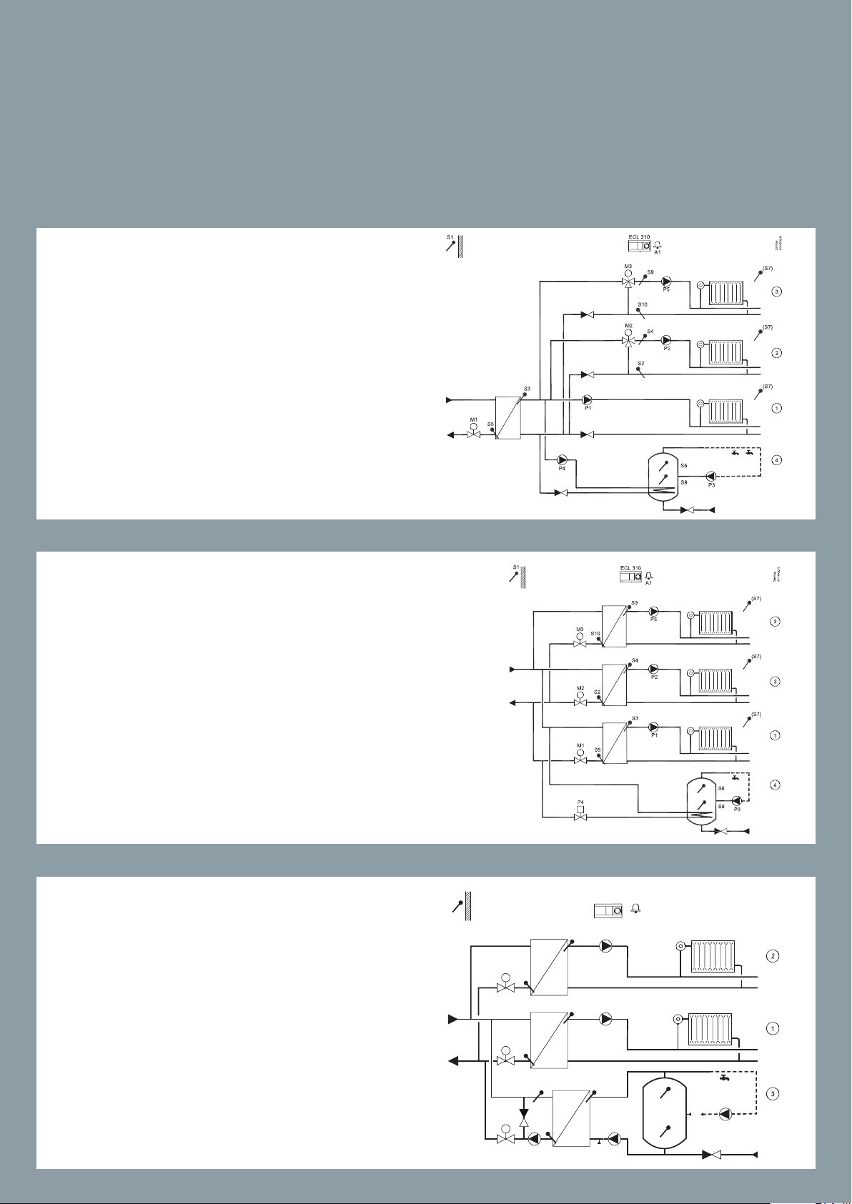
S1
87H2139.12
ECL 310
Subtypes A390.3, A390.11, A390.12 and A390.13 have for the control valve 3-point outputs as well as 0 – 10 V outputs.
A39 0.11
Example d
The heating circuits are indirectly connected. Two heating circuits are subcircuits to heating circuit 1.
DHW heating circuit 4 is combined with
circuit 1. DHW priority.
A39 0.11
Example e
Three independent and indirectly connected heating circuits. DHW heating
circuit 4 is directly heated.
A1
A390.12
M3
S2
S4
P5
S3
Danfoss
Example a
Two indirectly connected heating circuits. One advanced DHW charging circuit. Optional DHW priority.
M2
S5
S9
M1
S10
P1
P2
S7
B
P4
S6
A
P3
S8
89
89
89

S1
87H2140.12
ECL Comfort 310 Application A390
Weather compensated control of ow temperature in heating circuits. Room temperature compensation and sliding return temperature limitation. Heating circuits work independent in parallel or circuit 2 / 3 after circuit 1.
Optional control of motorized control valves by means of analog signal, 0 - 10 volt, (3 x heating circuits only).
Temperature control in DHW circuit with storage tank, directly heated or charging system. Return temperature limita tion.
Optional DHW priority. Flow temperature control of 3 cooling circuits with room temperature compensation and return
temperature limitation. Cooling circuits work independent in parallel or circuit 2 and 3 after circuit 1.
Alarm function related to ow temperatures.
A390.12
Example b
Two indirectly connected heating circuits. Heating circuit 2 is a sub-circuit
to heating circuit 1. One advanced
DHW charging circuit. Optional DHW
priority.
A390.13
ECL 310
M3
S3
M2
S5
S9
M1
S10
P1
A1
S4
P5
S2
P2
S7
B
P4
S6
A
P3
S8
Danfoss
Example a
Two indirectly connected heating circuits and one DHW charging circuit.
Always DHW charging priority.
A390.13
Example b
Two indirectly connected heating circuits and one DHW heating circuit. Always DHW heating priority.
90
90
90

ECL Comfort Master/slave applications
Example showing connections between ECL 210 / 296 / 310 via the ECL 485 bus.
Only one outdoor temperature sensor is needed and is connected to the master.
Via the ECL 485 bus the master broadcasts to other ECL 210 / 296 / 310 (slaves):
- Outdoor temperature signal
- Time and date
- DHW heating activity
Master/slave system 1
In this example the master is an A266
application. The slaves are applications A237 and A260.
91
91

Example showing ECL 210 / 296 / 310 as master, controlling the main heat supply.
Outdoor temperature signal, time, date and DHW heating activity signals are broadcasted to the slaves (other ECL 210 / 296 / 310). Slaves having an address can for each circuit
send its desired ow temperature to the master. The master ensures that the highest
demand from the slaves is fulllled. Each circuit in the slaves can be set to close when
DHW heating activity is present in the master in order to prioritize the DHW heating.
Master/slave system 2
In this example the master is an A230
application. The slaves are applications A260 and twice A247.
92
92

ECL Comfort Code numbers
ECL Comfort controllers
Typ e Designation Code no.
ECL Comfort 110
ECL Comfort 110
ECL Comfort 110 w. timer program
ECL Comfort 110 w. timer program
ECL Comfort 210
ECL Comfort 210B
ECL Comfort 296
ECL Comfort 310
ECL Comfort 310
ECL Comfort 310B
Universal hardware – 230 V a.c. (base part is included)
Universal hardware – 24 V a.c. (base part is included)
Universal hardware – 230 V a.c. (base part is included)
Universal hardware – 24 V a.c. (base part is included)
Universal hardware – 230 V a.c. (base part is not included).
Universal hardware – 230 V a.c. (base part is not included).
Without display and dial. Requires a remote control unit, ECA 30 or ECA 31.
Universal hardware – 230 V a.c. (base part is not included).
Dimension (L x H): 144 x 96 mm
Universal hardware – 230 V a.c. (base part is not included).
Universal hardware – 24 V a.c. (base part is not included).
Universal hardware – 230 V a.c. (base part is not included).
Without display and dial. Requires a remote control unit, ECA 30 or ECA 31.
08 7B1261
08 7B1251
087B1262
08 7B1252
087H3020
087H3030
087H3000
087H3040
087H3044
087H3050
ECL Comfort accessories
Typ e Designation Code no.
ECL Comfort 210/210 B base part For mounting on wall or DIN rail (35 mm “top hat” type). 087H3220
ECL Comfort 296 base part For mounting on wall or DIN rail (35 mm “top hat” t ype). 087H3240
ECL Comfort 296 panel kit
ECL Comfort 310/310 B base part
ECA 30
ECA 31
ECA 30/31 frame kit for mounting in
panel front
ECA 32
ECA 35
ECA 99 230 V a.c. to 24 V a.c. transformer (35 VA). 087 B115 6
ECA 110 Timer module for ECL Comfort 110 (the code no.s 087B1251 and 087B1261) 08 7B1248
DLG
For mounting in a panel cut-out (138 x 92 mm). Contains 2 x terminal blocks and clamps.
For mounting on wall or DIN rail (35 mm “top hat” t ype). Has space for the extension module ECA 32
or ECA 35. ECL Comfort 210 can be mounted in an ECL Comfort 310 base part (for future upgrade).
Remote control unit for ECL 210 / 210 B / 296 / 310 / 310 B with integrated room temp. sensor. Possibility
for connecting an external room temp. sensor (base par t for mounting on wall included).
Remote control unit for ECL 210 / 210 B / 296 / 310 / 310 B w. integrated ro om temp. sensor and relative
humidity sensor. Possibility for connecting an external room temp. sensor. Base part included.
For mounting in a cut-out.
Format 144 x 96 mm, actual cut-out 138 x 92 mm.
Internal I/O extension module for ECL Comfort 310. Analog outputs. To be inserted in the ECL 310
base part.
Internal I/O extension module for ECL Comfort 310. Analog and PWM outputs. To be inserted in the
ECL 310 base part.
Danfoss Link Gateway. Communication between ECL Comfor t 110 and Danfoss Living Connec t thermostats.
087H3242
087H3230
087H3200
087H3201
087H3236
087H3202
087H3205
087H3241
93
93

ECL Comfort Code numbers
ECL Comfort 110 instructions
Typ e English Danish Swedish
116 087B 8151 0 87B8153 087B 8155
130 087B8152 087B 8154 0 87B8156
Safety thermostats
Typ e Designation Code no.
ST-1
ST-2 Thermostat (TR) and safety limit (STB) with manual reset 087N1051
Sensor
pocket
Thermostat (TR) and safety monitor (ST W) with automatic
reset
For ST-1 and ST-2 08 7N1201
087N1050
Temperature sensors for ECL Comfort controllers
Typ e Designation Code no.
ESMT
ESM-10
ESM-11
Outdoor temperature sensor
Room temperature sensor
Pipe surface temperature sensor
08 4N1012
087 B116 4
087 B116 5
ES MB-12
ESMC
ESMU-100
ESMU-250
ESMU -100
ESMU-250
Pocket 100 mm
Pocket 250 mm
Pocket 100 mm
Pocket 250 mm
Universal temperature sensor with 2.5 m cable
Pipe surface temperature sensor
Immersion sensor, 100 mm, copper
Immersion sensor, 250 mm, copper
Immersion sensor, 100 mm, stainless steel
Immersion sensor, 250 mm, stainless steel
stainless steel, for ESMU-100, copper
stainless steel, for ESMU-250, copper
stainless steel, for ESMB-12
stainless steel, for ESMB-12
087 B118 4
087 N0 011
087B1180
087 B1181
087 B118 2
087 B118 3
087 B119 0
087 B1191
087 B119 2
087B1193
94
94

ECL Comfort Additional accessories
Differential pressure switch and Alarm pressure switches
Typ e Differential pressure range Electrical contact type Code no.
Differential pressure switch, Danfoss type
RT 262A
Alarm pressure switch BCP
Alarm pressure switch KPI 35
* depending on application (control, high limiter, low limiter) and pressure range
0,1 - 1,5 bar
- SPDT - gold
0,2 - 8 bar SPDT - silver/gold
Comparison
ECL 110 ECL 210 ECL 296 ECL 310
Flow / energy limitation
M-bus
TCP / IP (Internet)
24 Volt a.c.
Inputs, temp. sensor (Pt 1000)
Inputs, 0 - 10 V
X
max. 4 max. 8 max. 8
max. 2 max. 2
SPDT - silver
SPDT - gold available on request
X X
017D002566 (silver)
*
060-121766 (silver)
060-504766 (gold)
X
X
X
X
X
X
max. 10
max. 4
Inputs, digital
Inputs, ECA 32
Inputs, ECA 35
Pulse inputs, ECA 32 / 35 2
Outputs, 0 - 10 V 3 (ECA 32 / 35)
Outputs, PWM 4 (ECA 35)
Relay outputs, max.
Relay outputs, ECA 32 / 35 4 (2 x CO and 2 x NC)
Integration w. Danfoss Link
Dimensions, front (L x H mm)
Optional panel mounting
TM
1 4 4
DLG
148 x 104 220 x 110 144 x 96
yes no yes
max. 2 max. 2
max. 4
max. 6 (Pt 1000 / digital /
0 - 10 V)
max. 2 (Pt 1000 / digital /
0 - 10 V)
6
220 x 110
no
95
95

ECL Comfort application keys and languages
ECL Comfort 210 + 296 + 310
Application keys
Application type Code no.
A214 also covering A314 087H 3811
A217 also covering A317 087H3807
A230 087H3802
A231 also covering A331 087H3805
A232 also covering A332 087H 3812
A237 also covering A337 087H3806
A247 also covering A347 087H3808
Application keys
Available languages
Languages
Bulgarian Italian
Croatian Latvian
Czech Lithuanian
Danish Polish
Dutch Romanian
English Russia
Estonian Serbian
A260 087H3801
A266 087H3800
A275 also covering A375 0 87H3814
A319 087H3847
A333 087H 3818
A361 087H3804
A362 087H3845
A367 0 87H3813
A368 087H3803
A376 087H3810
Finnish Slovak
French Slovenian
German Spanish
Hungarian Swedish
Please visit
www.ecl.doc.danfoss.com
and find all relevant documentation
for the ECL Comfort series
A377 087 H3817
A390 087H3 815
96
96

High performance made easy
The ECL Comfort controller is designed to function as the intelligent hub of a heating system or a district heating
substation. The ECL Comfort controller is designed and developed with your needs in mind and incorporates a range
of features that enable you to achieve high performance.
Clever communication
The ECL Comfort 296 and 310 offer
state-of-the-art options for communication interfaces, such as Modbus, MBus and USB for service purposes. The
application range of the ECL Comfort
310 can be extended with the module
ECA 32.
Automatic setup of
DHW parameters
With advanced ECL Auto Tuning, control parameters for domestic hot water production can be configured and
optimised automatically, ensuring
both higher comfort and additional
energy savings.
Tap Water T (°C)
Faster installation
Improved cable connectors and
more space for wiring ensure
fast and trouble free installation of the
ECL Comfort controller in the system.
Longer lifetime
The ECL Comfort controllers feature
a unique motor protection function,
which prevents instability in the system, thus protecting acutators and
control valves against unnecessary activity. This results in up to 25% longer
lifetime of these components.
97
Easy interaction
The ECL Comfort controller has a large
display with graphic text and a backlight. Supported by intuitive menu
navigation, turn/push dial and the setup wizard, this makes the interaction
straightforward.
97

Easy, Eective, ECL
Danfoss A/S · Danfoss Heating Segment · DK-6430 Nordborg · Denmark
T
Danf
This also applies to produc
All trademarks in this material are proper
Access your ECL controllers via PC or smartphone
The ECL Portal application for the electronic controller ECL Comfort 310 is
an easy-to-use SCADA tool for control of your district heating system. ECL Portal enables you to streamline service, commissioning and maintenance – directly from your PC or smartphone,
wherever you are.
Increase your service levels and reduce costs with 24/7
access and control and get a complete overview of
energy consumption data, temperatures and ow.
The result is optimum performance and actual energy savings.
Real benets, real savings
The ECL Portal allows you to:
Increase long-term system performance
Gain a higher level of awareness and transparency of
the energy consumption
Improve service level and reduce response time to
alarms
Do troubleshooting without having to visit the heating
system
Feel free to contact us or visit www.ecl.portal.danfoss.com
for further information.
el.: +45 74 88 22 22 · Email: heating@danfoss.com · www.heating.danfoss.com
oss can accept no responsibility for possible errors in catalogues, brochures and other printed material. Danfoss reserves the right to alter its products without notice.
VGGUA602 © Copyright Danfoss Heating Segment | Pravda.dk | 2019
ts already on order provided that such alterations can be made without subsequential changes being necessary in specifications already agreed.
ty of the respective companies. Danfoss and the Danfoss logotype are trademarks of Danfoss A/S. All rights reserved.
 Loading...