

Page 1
Operating Guide
ECL Comfort 110, application 130
(valid as of software version 1.08)
English version
www.danfoss.com
Page 2
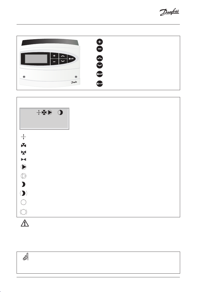
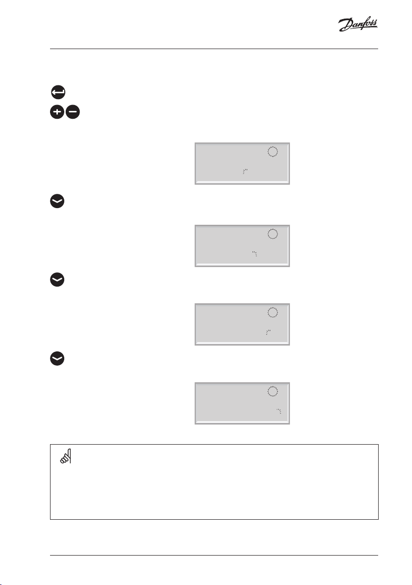
How to navigate?
What do the symbols mean?
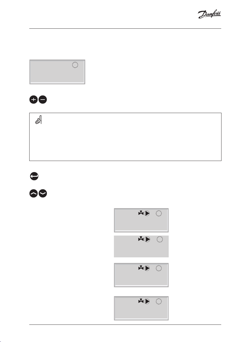
1000
Temp. 48@½
Mode COMFORT<
The desired flow temperature is influenced by for example return temperature.
The actuator closes the control valve.
The actuator opens the control valve.
The actuator does not activate the valve.
The pump is ON.
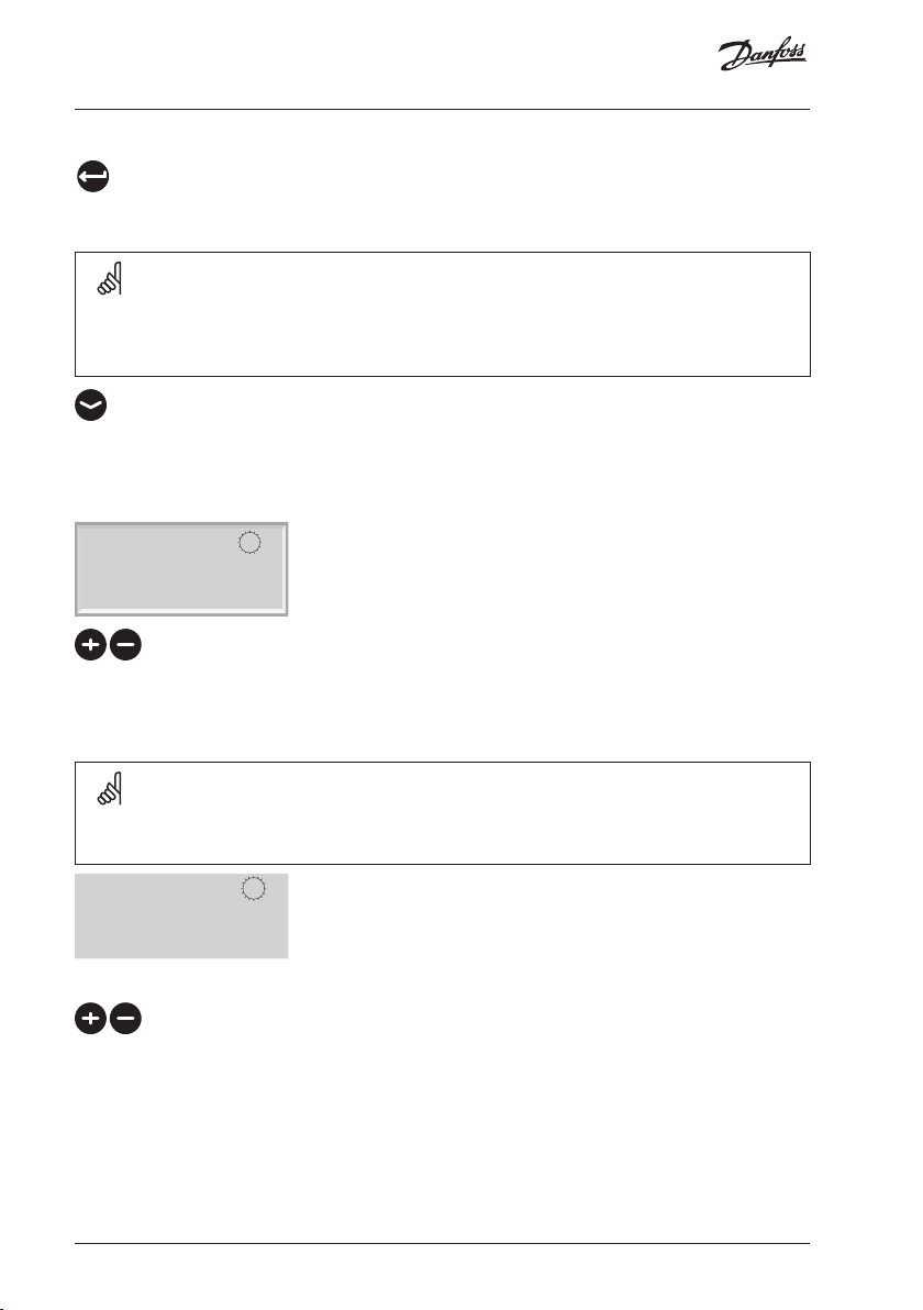
Adjust temperatures and values.
Switch between menu lines.
Select / return.
2 sec.
Return to daily user menu.
The pump is OFF.
The controller is in setback mode.
The controller is in pre-setback mode (the symbol is blinking).
The controller is in comfort mode.
The controller is in pre-comfort mode (the symbol is blinking).
Safety Note
To avoid injury of persons and damages to the device, it is absolutely necessary to read and
observe these instructions carefully. The warning sign is used to emphasize special conditions
that should be taken into consideration.
This symbol indicates that this particular piece of information should be read with
special attention.
2 | © Danfoss | 2021.01
AQ188586469712en-010801
Page 3
Table of contents
Weather compensated flow temperature control of heating and boiler systems
User guide, installation & maintenance
Table of contents Line Page
Introduction 5
Settings overview 6
Daily use 7
Temperatures 7
Select control mode 8
Set your personal schedule 8
Maintenance 10
Date - time 1000 10
Flow temp. (flow temperature control) 2000 10
Slope 2175 11
Displace (parallel displacement) 2176 13
Temp. min. (flow temp. limit, min.) 2177 13
Temp. max. (flow temp. limit, max.) 2178 13
Room T limit (room temperature limitation) 3000 14
Intgr. time (time constant for room temp.) 3015 16
Gain - max. (room temp. limitation, max.) 3182 16
Gain - min. (room temp. limitation, min.) 3183 16
Return T limit (return temp. limitation) 4000 17
Limit (return temp. limitation) 4030 17
Gain - max. (return temp. limitation - max. influence) 4035 18
Gain - min. (return temp. limitation - min. influence) 4036 18
Intgr. time (time constant for return temp. limitation) 4037 19
Priority (priority for return temp. limitation) 4085 19
Optimize 5000 20
Auto-reduct (setback temp. dependent on outdoor temp.) 5011 20
Boost 5012 20
Ramp (reference ramping) 5013 21
Optimizer (optimizing time constant) 5014 21
Based on (optimization based on room / outdoor temp.) 5020 22
Total stop 5021 23
S1 T filter (outdoor temp. filter) 5081 23
Cut-out (limit for heating cut-out) 5179 24
AQ188586469712en-010801 © Danfoss | 2021.01 | 3
Page 4
Table of contents
Control param. (control parameters) 6000 25
Motor prot. (motor protection) 6174 25
Xp (proportional band) 6184 25
Tn (integration time constant) 6185 25
M1 run (running time of the motorized control valve) 6186 25
Nz (neutral zone) 6187 26
Application 7000 28
ECA address (choice of room panel / remote control) 7010 28
P1 exercise (pump exercise) 7022 28
M1 exercise (valve exercise) 7023 28
Actuator (gear motor / thermo actuator) 7024 28
DHW prior. (closed valve / normal operation) 7052 29
P1 frost T (frost protection) 7077 29
P1 heat T (heat demand) 7078 30
Standby T (standby temperature) 7093 30
Ext. (external override) 7141 30
Knee point 7162 31
Min. on time (min. activation time gear motor) 7189 31
Daylight (daylight saving time changeover) 7198 31
ECL address (master / slave address) 7199 31
Type 7600 32
Service 8000 33
Code no. 8300 33
Ver. (version no.) 8301 33
Backlight (display brightness) 8310 33
Contrast (display contrast) 8311 33
Language 8315 34
MOD address (MODBUS address) 8320 34
Installation 35
Mounting the ECL Comfort controller 35
Electrical connections - 230 V a.c. - in general 36
Electrical connections - 24 V a.c. - in general 37
Connecting the temperature sensors and the ECL BUS 38
How to identify your system type 39
Adapting the ECL Comfort 110 controller 41
Manual control 42
Placing the temperature sensors 43
Connecting the room panel / remote control 44
Checklist, electrical connections 45
Frequently asked questions 46
Definitions 47
4 | © Danfoss | 2021.01
AQ188586469712en-010801
Page 5
Introduction
How to use this guide
The instructions is divided into six parts:
• Introduction
• Settings overview
• Daily use
• Maintenance
• Installation
• Check
Basic principles of application 130 for ECL Comfort 110
Typically, the flow temperature is always adjusted according to your requirements.
The flow temperature sensor (S3) is the most important sensor. The desired flow
temperature at S3 is calculated in the ECL Comfort controller, based on the outdoor
temperature (S1). The lower the outdoor temperature, the higher the desired flow
temperature.
The motorized control valve (M1) is opened gradually when the flow temperature is
lower than the desired flow temperature and vice versa.
The return temperature (S4) to the district heating supply should not be too high. If so,
the desired flow temperature can be adjusted (typically to a lower value) thus resulting
in a gradual closing of the motorized control valve. In boiler-based heating supply the
return temperature should not be too low (same adjustment procedure as above).
If the measured room temperature does not equal the desired room temperature, the
desired flow temperature can be adjusted.
The circulation pump, P1, is ON when the desired flow temperature is higher than 20 °C
(factory setting) or the outdoor temperature is lower than 2 °C (factory setting).
°C (degrees Celsius) is an absolute temperature whereas K (Kelvin) is a relative temperature.
AQ188586469712en-010801 © Danfoss | 2021.01 | 5
Page 6
Settings overview
Line Page
Slope 2175 11
Displace (parallel displacement) 2176 13
Temp. min. (flow temp. limit, min.) 2177 13
Temp. max. (flow temp. limit, max.) 2178 13
Intgr. time (time constant for room temp.) 3015 16
Gain - max. (room temp. limitation, max.) 3182 16
Gain - min. (room temp. limitation, min.) 3183 16
Limit (return temp. limitation) 4030 17
Gain - max. (return temp. limitation - max. influence) 4035 18
Gain - min. (return temp. limitation - min. influence) 4036 18
Intgr. time (time constant for return temp. limitation) 4037 19
Priority (priority for return temp. limitation) 4085 19
Auto-reduct (setback temp. dependent on outdoor temp.) 5011 20
Boost 5012 20
Ramp (reference ramping) 5013 21
Optimizer (optimizing time constant) 5014 21
Based on (optimization based on room / outdoor temp.) 5020 22
Total stop 5021 23
S1 T filter (outdoor temp. filter) 5081 23
Cut-out (limit for heating cut-out) 5179 24
Motor prot. (motor protection) 6174 25
Xp (proportional band) 6184 25
Tn (integration time constant) 6185 25
M1 run (running time of the motorized control valve) 6186 25
Nz (neutral zone) 6187 26
ECA address (choice of room panel / remote control) 7010 28
P1 exercise (pump exercise) 7022 28
M1 exercise (valve exercise) 7023 28
Actuator (gear motor / thermo actuator) 7024 28
DHW prior. (closed valve / normal operation) 7052 29
P1 frost T (frost protection) 7077 29
P1 heat T (heat demand) 7078 30
Standby T (standby temperature) 7093 30
Ext. (external override) 7141 30
Knee point 7162 31
Min. on time (min. activation time gear motor) 7189 31
Daylight (daylight saving time changeover) 7198 31
ECL address (master / slave address) 7199 31
Type 7600 32
Code no. 8300 33
Ver. (version no.) 8301 33
Backlight (display brightness) 8310 33
Contrast (display contrast) 8311 33
Language 8315 34
MOD address (MODBUS address) 8320 34
Factor y
setting
1.2
10 °C
90 °C
OFF
-4.0
0.0
50 °C
-2.0
0.0
25 s
OFF
-15 °C
OFF
OFF
OFF
OUT
OFF
100
18 °C
OFF
80 K
30 s
35 s
3 K
OFF
ON
OFF
GEAR
OFF
2 °C
20 °C
10 °C
OFF
40 °C
ON
130
XXXX
XXXX
English
!
Your setting
0
10
15
16
10
5
6 | © Danfoss | 2021.01
AQ188586469712en-010801
Page 7
Daily use
Temperatures
Push any button to switch on the backlight.
Temp. 19 <
Mode COMFORT
Setting the desired room temperature
Change the desired temperature.
The setting of the desired room temperature is important even if a room temperature sensor
/ room panel / remote control is not connected.
Is the room temperature too low?
Make sure that the radiator thermostat(s) does not limit the room temperature.
If you still cannot obtain the desired room temperature by adjusting the radiator
thermostats, the flow temperature is too low. Increase the desired room temperature.
Temperature overview
2 sec.
Push the button to see the sensor (S1-S4) temperatures.
Change between the temperature displays:
S1:
Actual outdoor temperature
Accumulated outdoor temperature
S1 act. T 13@
S1 acc. T 12@
S2:
Actual room temperature
Desired room temperature
S3:
Actual flow temperature
Desired flow temperature
S4:
Actual return temperature
Desired return temperature limitation
AQ188586469712en-010801 © Danfoss | 2021.01 | 7
S2 act. T 20@
S2 des. T 21@
S3 act. T 43@
S3 des. T 42@
S4 act. T 28@
S4 lim. T 30@
Page 8
Daily use
Push to exit ‘Temperature overview’.
If the temperature value is displayed as
"- -" the sensor in question is not connected.
"- - -" the sensor is short-circuited.
Select control mode
During scheduled operation (AUTO), the symbols will show you the control mode.
Mode COMFORT<
Wednesday
Change the mode (AUTO, COMFORT, SETBACK, or STANDBY).
Set your personal schedule
It is only possible to set the personal schedules if the ECL Comfort 110 controller has a built-in
ECA 110 timer program.
Wednesday <
04-01-12 8:32
This display will show the current day and time.
Choose the day for which you wish to change the settings.
8 | © Danfoss | 2021.01
AQ188586469712en-010801
Page 9
Daily use
Today’s schedule
The first display will show you the start of the first comfort period (‘Start1’). See or change
the start of this period.
The first bar will blink.
Start1
09:00
Wed ]]]][!]]]!!]
See or change the end (‘Stop1’) of the first comfort period.
The next bar will blink.
Stop1 12:00
Wed ]]]][!{]]!!]
See or change the start (‘Start2’) of the next comfort period.
Start2 18:00
Wed ]]]][!{]]!!]
See or change the next start / stop periods, if necessary.
Stop2 22:00
Wed ]]]][!{]]!!]
The schedule has always two comfort periods a day. The start and stop times can be set in
half-hourly intervals (30 min.).
To arrange only one comfort period on a day: Set Start2 and Stop2 times to the same time
value.
AQ188586469712en-010801 © Danfoss | 2021.01 | 9
Page 10
Maintenance
2 sec.
Enter the maintenance menus.
Date - time 1000
It is only necessary to set the correct date and time in connection with the first use of the
ECL Comfort 110 controller or after a power break of more than 36 hours (see the chapter
on Adapting the ECL Comfort 110 controller).
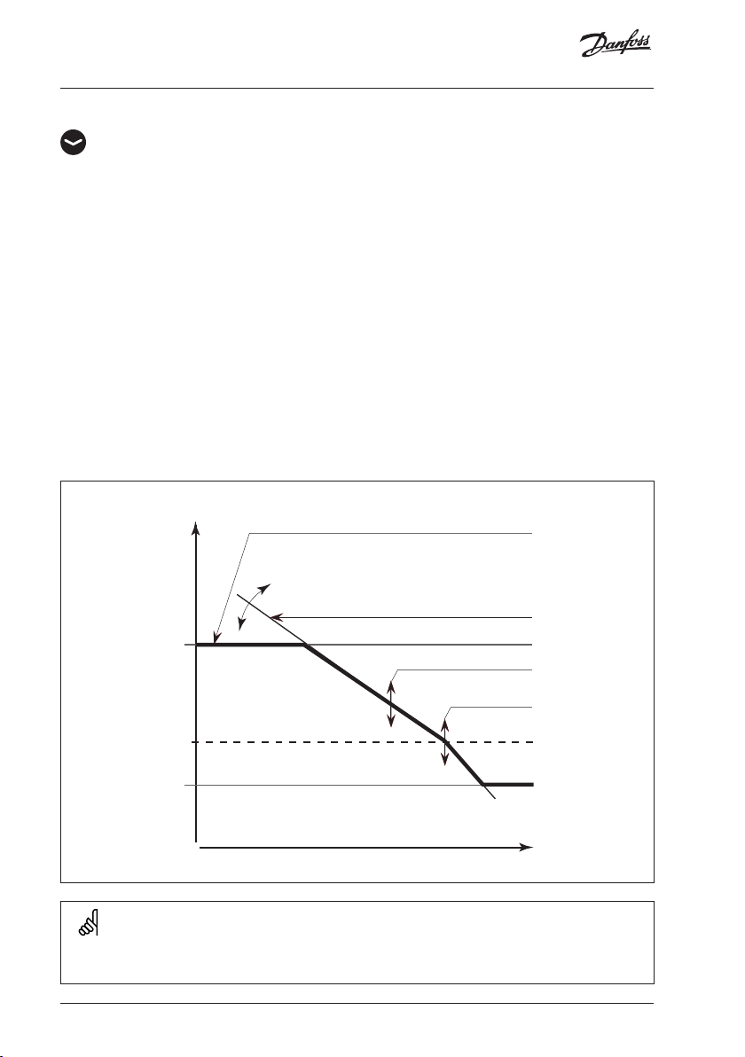
Flow temp. (flow temperature control) 2000
Heat curve
The ECL Comfort 110 controls the heating system according to the calculated flow
temperature under the influence of the return and / or room temperature.
The desired flow temperature is defined by 5 settings: ‘Temp. max.’, ‘Temp. min.’, ‘Slope’,
‘Displace’, and ‘Knee point’.
Desired flow temperature
[°C]
110
100
90
80
70
60
50
40
30
20
10
-20 -10 0 10 20-30
Heat cur ve
‘Slope’
‘Te mp. max .’
‘Displace’
‘Knee point’
‘Te mp. min.’
Outdoo r temp.
[°C]
The calculated flow temperature can be influenced by connected sensors, ‘Boost’ and ‘Ramp’
etc.
10 | © Danfoss | 2021.01
AQ188586469712en-010801
Page 11
Maintenance
Slo p e 2175
Setting range Factory setting
Adjust the ‘Slope’ of the heat curve, if required.
The heat curve slope depends on the heating system and area specific design
parameters.
Example I
Design parameter:
Designed outdoor temperature (T
Designed flow temperature (T
Designed room temperature (T
For designed flow temperature higher than 40 °C, the heat curve slope (S) can be
calculated as:
T
- 25
S =
2.5 x T
flow
room
- T
- 30
out
0.1 ... 4.0 1.2
) -12 °C
out
) 80 °C
flow
) 20 °C
room
S =
80 - 25
2.5 x 20 - (- 12) - 30
S ≈ 1.7
Example II
Design parameter:
Designed outdoor temperature (T
Designed flow temperature (T
Designed room temperature (T
) -20 °C
out
) 35 °C
flow
) 21 °C
room
For designed flow temperatures lower than 40 °C, the heat curve slope (S) can be
calculated as:
T
- 20
S =
1.3 (2.5 x T
flow
room
- T
out
- 30)
35 - 20
S =
1.3 (2.5 x 21 - (- 20) - 30)
S ≈ 0.3
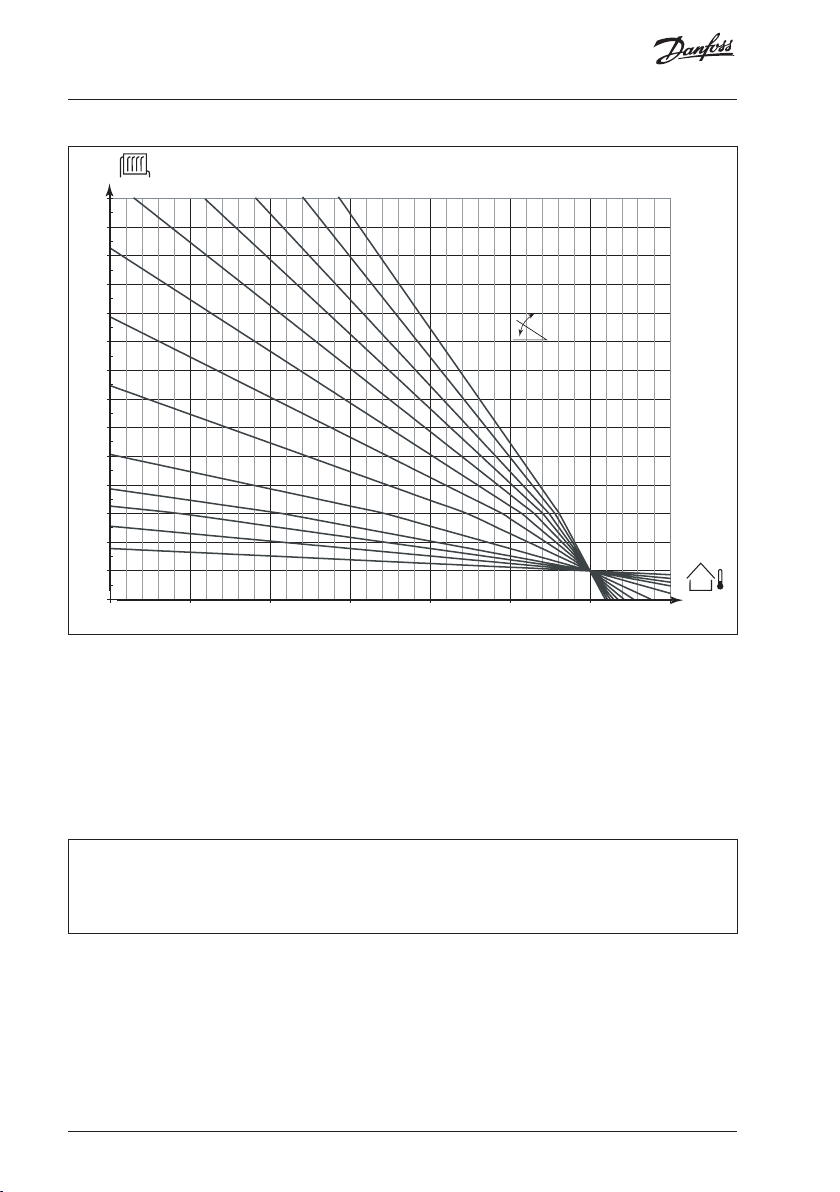
For quick setting, the graph can be used. The graph is intended for a T
design data from example I is used, the slope will be approx. 1.7.
AQ188586469712en-010801 © Danfoss | 2021.01 | 11
of 20 °C. If the
room
Page 12
Maintenance
100
110
120
130
140
150
-40-30 -20-10 0102030
[oC]
[oC]
2.2 3.0 3.52.6 4.0
1.8
1.4
90
1.0
80
70
0.6
60
0.4
50
0.3
40
0.2
0.1
30
20
10
How to determine another heat curve, if necessary:
Choose the calculated flow temperature for your system and the determined min.
outdoor temperature for your area. Pick the heat curve closest to the crossing point of
these two values.
The setting of the desired room temperature has an influence on the calculated flow
temperature (heat curve), no matter if a room temperature sensor is connected or not.
Floor heating systems
This controller is factory set for radiator systems, which typically are high flow temperature
systems. To control floor heating systems, which typically are low flow temperature systems,
you need to change the ‘Slope’ according to your type of system (typical setting: 0.6).
12 | © Danfoss | 2021.01
AQ188586469712en-010801
Page 13
Maintenance
Displace (parallel displacement) 2176
Setting range Factory setting
-20 ... 20 0
Adjust the parallel displacement of the heat curve with a number of degrees, if required.
Whether it is reasonable to change the ‘Slope’ (at outdoor temperatures below 0 °C) or
parallel displacement (at outdoor temperatures above 0 °C) will depend on the individual
heat requirement.
Small increases or reductions in the heating temperature can be implemented by means of
the parallel displacement.
Temp. min. (flow temp. limit, min.) 2177
Setting range Factory setting
10 ... 150 °C 10 °C
Choose the allowed min. flow temperature for your system. Adjust the factory setting, if
required.
Temp. max. (flow temp. limit, max.) 2178
Setting range Factory setting
10 ... 150 °C 90 °C
Choose the allowed max. flow temperature for your system. Adjust the factory setting, if
required.
The setting for ‘Temp. max.’ has higher priority than ‘Temp. min.’.
AQ188586469712en-010801 © Danfoss | 2021.01 | 13
Page 14
Maintenance
Room T limit (room temperature limitation) 3000
This section is only relevant if you have installed a room temperature sensor or room
panel / remote control.
The controller adjusts the desired flow temperature to eliminate the difference between
the desired and the actual room temperature.
There are two basic principles for control of the room temperature.
A: Max. room temperature limitation
Use this limitation if your heating system is fully equipped with thermostats and you also
want to obtain a max. limitation of the room temperature. The controller will allow for
free heat gains, i.e. solar radiation or heat from a fire place, etc.
Influence
‘Gain - min.’ (min. limitation)
Desired room temperature
Actual room temperature
‘Gain - max.’ (max. limitation)
The ‘Gain - max.’ determines how much the room temperature should influence the
desired flow temperature.
If the ‘Gain’ is too high and / or the ‘Intgr. time’ too low, there is a risk of unstable control.
Exa mple A1
The actual room temperature is 2 degrees too high.
The ‘Gain - max.’ is set to -4.0.
The ‘Gain - min.’ is set to 0.0.
The ‘Slope’ is 1.8.
Result:
The desired flow temperature is changed by 2 x -4.0 x 1.8 = -14.4 degrees.
14 | © Danfoss | 2021.01
AQ188586469712en-010801
Page 15
Maintenance
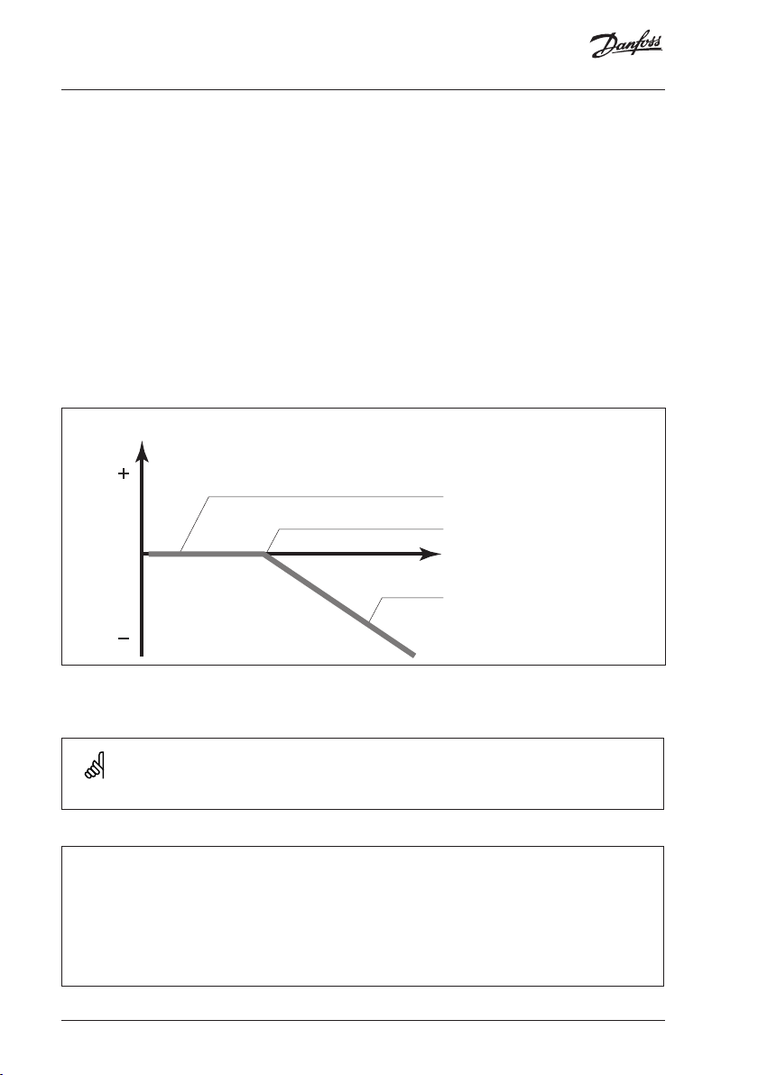
B: Reference room temperature control
Used if your heating system is not equipped with thermostats and you select the room
with room temperature sensor as a temperature reference for the rest of the rooms.
Set a positive value for the ‘Gain - min.’ and a negative value for the ‘Gain - max.’.
Influence
‘Gain - min.’ (min. limitation)
Desired room temperature
Actual room temperature
‘Gain - max.’ (max. limitation)
The room temperature sensor in the reference room measures the actual room
temperature.
If a difference occours between the actual and the desired room temperature, the
desired flow temperature can be corrected. The correction is based on the settings in the
lines 3182 and 3183. This correction of the desired flow temperature will normally give a
correct room temperature. See also line 3015.
Example B1
The actual room temperature is 2 degrees too low.
The ‘Gain - max.’ is set to -3.5.
The ‘Gain - min.’ is set to 2.0.
The ‘Slope’ is 1.8.
Result:
The desired flow temperature is changed by 2 x 2.0 x 1.8 = 7.2 degrees.
Example B2
The actual room temperature is 2 degrees too high.
The ‘Gain - max.’ is set to -3.5.
The ‘Gain - min.’ is set to 2.0.
The ‘Slope’ is 1.8.
Result:
The desired flow temperature is changed by 2 x (-3.5) x 1.8 = -12.6 degrees.
AQ188586469712en-010801 © Danfoss | 2021.01 | 15
Page 16
Maintenance
This limitation is based on a PI regulation where P (Gain) responds quickly to deviations
and I (Intgr. time) responds slower and over time removes the small offsets between the
desired and actual values. This is done by changing the desired flow temperature.
Intgr. time (time constant for room temp.) 3015
Setting range Factory setting
OFF / 1 ... 50 OFF
Controls how fast the room temperature adapts to the desired room temperature (I control).
OFF: The control function is not influenced by the ‘Intgr. time’.
1: The desired temperature is adapted quickly.
50: The desired temperature is adapted slowly.
Gain - max. (room temp. limitation, max.) 3182
Setting range Factory setting
-9.9 ... 0.0 -4.0
Determines how much the flow temperature will be influenced (decreased) if the room temperature is
higher than the desired room temperature (P control).
-9.9: The room temperature has a big influence.
0.0: The room temperature has no influence.
Gain - min. (room temp. limitation, min.) 3183
Setting range Factory setting
0.0 ... 9.9 0.0
Determines how much the flow temperature will be influenced (increased) if the room temperature is
lower than the desired room temperature (P control).
0.0: The room temperature has no influence.
9.9: The room temperature has a big influence.
16 | © Danfoss | 2021.01
AQ188586469712en-010801
Page 17

Maintenance
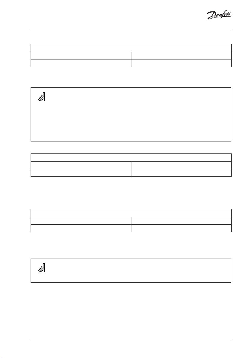
Return T limit (return temp. limitation) 4000
The controller automatically changes the desired flow temperature to obtain an
acceptable return temperature when the return temperature falls below or gets higher
than the set limit.
Influence
‘Gain - min.’ > 0
‘Limit’
‘Gain max.’ > 0
Return temperature
‘Gain - max.’ < 0
‘Gain - min.’ < 0
This limitation is based on a PI regulation where P (Gain) responds quickly to deviations
and I (Intgr. time) responds slower and over time removes the small offsets between the
desired and actual values. This is done by changing the desired flow temperature.
If the ‘Gain’ is too high and / or the ‘Intgr. time’ too low, there is a risk of unstable control.
Limit (return temp. limitation) 4030
Setting range Factory setting
10 ... 110 °C 50 °C
Set the return temperature you accept for the system.
Set the acceptable return temperature limit.
When the return temperature falls below or gets higher than the set value, the controller
automatically changes the desired flow temperature to obtain an acceptable return
temperature. The influence is set in lines 4035 and 4036.
AQ188586469712en-010801 © Danfoss | 2021.01 | 17
Page 18

Maintenance
Gain - max. (return temp. limitation - max. influence) 4035
Setting range Factory setting
-9.9 ... 9.9 -2.0
Determines how much the flow temperature will be influenced if the return temperature is higher than
the desired ‘Limit ’ (line 4030) (P control).
Influence higher than 0:
The desired flow temperature is increased, when the return temperature gets higher
than the set limit.
Influence lower than 0:
The desired flow temperature is decreased, when the return temperature gets higher
than the set limit.
Example
The return limit is active above 50 °C.
The influence is set to -2.0.
The actual return temperature is 2 degrees too high.
Result:
The desired flow temperature is changed by -2.0 x 2 = -4.0 degrees.
Normally, the setting in line 4035 is lower than 0 in district heating systems to avoid a too
high return temperature.
Typically, the setting in line 4035 is 0 in boiler systems because a higher return temperature
is acceptable (see also line 4036).
Gain - min. (return temp. limitation - min. influence) 4036
Setting range Factory setting
-9.9 ... 9.9 0.0
Determines how much the flow temperature will be influenced if the return temperature is lower than
the desired ‘Limit ’ (line 4030) (P control).
Influence higher than 0:
The desired flow temperature is increased, when the return temperature gets below the
set limit.
Influence lower than 0:
The desired flow temperature is decreased, when the return temperature gets below the
set limit.
18 | © Danfoss | 2021.01
AQ188586469712en-010801
Page 19

Maintenance
Example
The return limit is active below 50 °C.
The influence is set to -3.0.
The actual return temperature is 2 degrees too low.
Result:
The desired flow temperature is changed by -3.0 x 2 = -6.0 degrees.
Normally, the setting in line 4036 is 0 in district heating systems because a lower return
temperature is acceptable.
Typically, the setting in line 4036 is higher than 0 in boiler systems to avoid a too low return
temperature (see also line 4035).
If the return temperature measurement is used as thermometer function only, the settings
in lines 4035 and 4036 should be 0.0.
Intgr. time (time constant for return temp. limitation) 4037
Setting range Factory setting
OFF / 1 ... 50 s 25 s
Controls how fast the return temperature adapts to the desired return temperature (I control).
OFF: The control function is not influenced by the ‘Intgr. time’.
1: The desired temperature is adapted quickly.
50: The desired temperature is adapted slowly.
Priority (priority for return temp. limitation) 4085
Setting range Factory setting
ON / OFF OFF
Choose whether the return temperature limitation should overrule the set min. flow temperature
‘Temp. min.’ (line 2177).
ON: The min. flow temperature limit is overruled.
OFF: The min. flow temperature limit is not overruled.
AQ188586469712en-010801 © Danfoss | 2021.01 | 19
Page 20

Maintenance
100%
Optimize 5000
Auto-reduct (setback temp. dependent on outdoor temp.) 5011
Setting range Factory setting
OFF / -29 ... 10 °C -15 °C
Below this outdoor temperature, the setback temperature setting has no influence.
-29 ... 10: The setback temperature depends on the outdoor temperature, when
the outdoor temperature is above the set limit. The lower the outdoor
temperature, the less the temperature reduction. When the outdoor
temperature is below the set limit, there is no temperature reduction.
OFF: The setback temperature does not depend on the outdoor temperature.
Reduction
Outdoo r
temp. °C
0%
-20 -10-29 02010
Setting line 5011
Bo ost 5012
Setting range Factory setting
OFF / 1 ... 99% OFF
Shortens the heating-up period by increasing the desired flow temperature by the percentage you set.
Set the percentage at which you want the desired flow temperature increased
temporarily.
In order to shorten the heating-up period after a setback temperature period, the desired
flow temperature can be increased temporarily (max. 1 hour). At optimizing the boost is
active in the optimization period (line 5014).
If a room temperature sensor or a room panel / remote control is connected, the boost
stops when the room temperature is reached.
20 | © Danfoss | 2021.01
AQ188586469712en-010801
Page 21

Maintenance
Ramp (reference ramping) 5013
Setting range Factory setting
OFF / 1 ... 99 m OFF
The time in which the desired flow temperature increases gradually to avoid load peaks in the heat
supply.
Set the ramping time for the controller.
Tem p. °C
Time (min.)
Setting line 5013
In order to avoid load peaks in the supply network, the flow temperature can be set to
increase gradually after a period with setback temperature. This causes the valve to open
gradually.
Optimizer (optimizing time constant) 5014
Setting range Factory setting
OFF / 10 ... 59 OFF
Optimizes the start and stop times for the comfort temperature period to obtain the best comfort at the
lowest energy consumption. The lower the outdoor temperature, the earlier the heating cut-in.
Adjust the optimizing time constant.
The value consists of a two digit number. The two digits have the following meaning:
Left digit Heat accumulation of the building System type
1X light
Radiator systems2X medium
3X heavy
4X medium
5X heavy
AQ188586469712en-010801 © Danfoss | 2021.01 | 21
Floor heating systems
Page 22

Maintenance
Right digit Dimensioning temperature Capacity
X0 -50 °C large
X1 -45 °C •
• • •
X5 -25 °C normal
• • •
X9 -5 °C small
OFF: No optimization. The heating starts and stops at the times set in the
schedule.
Dimensioning temperature:
The lowest outdoor temperature (usually determined by your system designer in connection
with the design of the heating system) at which the heating system can maintain the
designed room temperature.
Example
The system type is radiator, and the heat accumulation of the building is medium.
The left digit is 2.
The dimensioning temperature is -25 °C, and the capacity is normal.
The right digit is 5.
Result:
The setting is to be changed to 25.
It is only possible make use of ‘Optimize’ if the ECL Comfort 110 controller has a built-in ECA
110 timer program or is connected to an ECA 61.
Based on (optimization based on room / outdoor temp.) 5020
Setting range Factory setting
ROOM / OUT OUT
The optimized start and stop time can be based on either room or outdoor temperature.
ROOM: Optimization based on room temperature, if measured.
OU T: Optimization based on outdoor temperature. Use this setting if the
room temperature is not measured.
22 | © Danfoss | 2021.01
AQ188586469712en-010801
Page 23

Maintenance
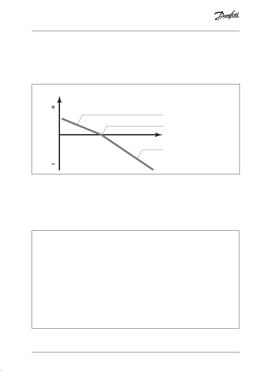
Total stop 5021
Setting range Factory setting
ON / OFF OFF
Decide whether you want a total stop during the setback temperature period.
ON: The desired system temperature is lowered to ‘Standby T’ (line 7093).
‘Temp. min.’ (line 2177) is overruled.
Desired system temp. °C
‘Standby T’
Time
OFF: No total stop
Desired system temp. °C
‘Standby T’
Time
S1 T filter (outdoor temp. filter) 5081
Setting range Factory setting
1 ... 200 100
Dampens the measured outdoor temperatures by the set factor.
1: Fast (low filter constant)
200: Slow (high filter constant)
AQ188586469712en-010801 © Danfoss | 2021.01 | 23
Page 24

Maintenance
18 °C
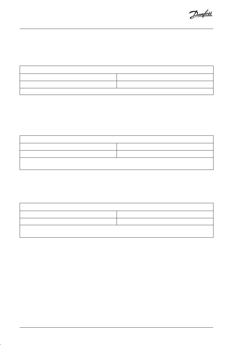
Cut-out (limit for heating cut-out) 5179
Setting range Factory setting
OFF / 1 ... 50 °C 18 °C
Set the outdoor temperature limit at which you want the heating system to stop. The
valve closes and after about 3 min. the heating circulation pump stops. ‘Temp. min.’
set in line 2177 will be ignored.
Temp. Actual outdoor temp. Accumulated outdoor temp.
Time
Heating Heating OFF Heating
This function can save energy by stopping the heating system when the outdoor
temperature gets above a set limit. The heating system switches ON again when the
outdoor temperature and the accumulated outdoor temperature become lower than
the set limit.
The heating cut-out is only active when the controller mode is AUTO (scheduled operation).
When the limit value is set to OFF, there is no heating cut-out.
24 | © Danfoss | 2021.01
AQ188586469712en-010801
Page 25

Maintenance
Control param. (control parameters) 6000
Motor prot. (motor protection) 6174
Setting range Factory setting
OFF / 10 ... 59 m OFF
Prevents the controller from unstable temperature control (and resulting actuator oscillations). This
can occur at very low load. The motor protection increases the lifetime of all involved components.
OFF: Motor protection is not activated.
10 ... 59: Motor protection is activated after the set activation delay.
Typically used for DHW applications. Can also be used for heating systems at very low load.
Xp (proportional band) 6184
Setting range Factory setting
1 ... 250 K 80 K
Set the proportional band. A higher value will result in a stable but slow control of the
flow temperature.
Tn (integration time constant) 6185
Setting range Factory setting
5 ... 999 s 30 s
Set a high integration time constant to obtain a slow but stable reaction to deviations.
A low integration constant will make the controller react fast but with less stability.
M1 run (running time of the motorized control valve) 6186
Setting range Factory setting
5 ... 250 s 35 s
‘M1 run’ is the time it takes the controlled unit to move from fully closed to fully open
position. Set the ‘M1 run’ according to the example.
AQ188586469712en-010801 © Danfoss | 2021.01 | 25
Page 26

Maintenance
How to calculate the running time of a motorized control valve
The running time of the motorized control valve is calculated using the following methods:
Seated valves
Running time = Valve stroke (mm) x actuator speed (sec. / mm)
Example: 5.0 mm x 15 sec. / mm = 75 sec.
Rotating valves
Running time = Turning degrees x actuator speed (sec. / degr.)
Example: 90 degr. x 2 sec. / degr. = 180 sec.
Nz (neutral zone) 6187
Setting range Factory setting
1 ... 9 K 3 K
Set the acceptable flow temperature deviation.
Set the neutral zone to a high value if you can accept a high variation in flow
temperature. When the actual flow temperature is within the neutral zone, the controller
does not activate the motorized control valve.
The neutral zone is symmetrical around the desired flow temperature value, i.e. half the
value is above and half the value is below this temperature.
26 | © Danfoss | 2021.01
AQ188586469712en-010801
Page 27

Maintenance
If you want to tune the PI regulation precisely, you can use the following
method:
• Set the ‘Tn’ (integration time constant line 6185) to its max. value (999 sec.).
• Decrease the value for the ‘Xp’ (proportional band line 6184) until the system starts
hunting with a constant amplitude (it might be necessary to force the system by setting
an extreme value).
• Find the critical time period on the temperature recording or use a stop watch.
Temp. Critical time period
Time
This time period will be characteristic for the system, and you can evaluate the settings from
this critical period.
‘Tn’ = 0.85 x critical time period
‘Xp’ = 2.2 x proportional band value in the critical time period.
If the regulation seems to be too slow, you can decrease the proportional band value by
10%.
AQ188586469712en-010801 © Danfoss | 2021.01 | 27
Page 28

Maintenance
Application 7000
ECA address (choice of room panel / remote control) 7010
Setting range Factory setting
OFF / A / B OFF
Decides the communication with the room panel or remote control.
OFF: Room temperature sensor (no room panel / remote control)
A: Remote control, ECA 61 with address A
B: Remote control, ECA 61 with address B
P1 exercise (pump exercise) 7022
Setting range Factory setting
ON / OFF ON
Exercises the pump to avoid blocking in periods without heat demand.
ON: The pump is switched ON for 1 minute every third day around noon.
OFF: The pump exercise is not active.
M1 exercise (valve exercise) 7023
Setting range Factory setting
ON / OFF OFF
Exercises the valve to avoid blocking in periods without heat demand.
ON: The valve receives a signal to open and close every third day around
noon.
OFF: The valve exercise is not active.
Actuator (gear motor / thermo actuator) 7024
Setting range Factory setting
GEAR / ABV GEAR
Choose the actuator t ype for your valve.
GEAR: Gear motor
ABV: Thermo actuator (Danfoss type ABV)
Control parameters (lines 6174-6187) are overruled if thermo actuator is chosen (ABV).
28 | © Danfoss | 2021.01
AQ188586469712en-010801
Page 29

Maintenance
DHW prior. (closed valve / normal operation) 7052
Setting range Factory setting
ON / OFF OFF
The heating circuit can be closed when the controller acts as slave and when DHW charging is active in
the master.
ON: The valve in the heating circuit is closed* during active DHW charging in
the master controller.
* The desired flow temperature is set to ‘Standby T’ (line 7093)
OFF: The flow temperature control remains unchanged during active DHW
charging in the master controller.
The setting in line 7052 must be considered if this controller is a slave.
P1 frost T (frost protection) 7077
Setting range Factory setting
OFF / -10 ... 20 °C 2 °C
When the outdoor temperature is below the set temperature in ‘P1 frost T’, the controller automatically
switches ON the circulation pump to protect the system.
OFF: No frost protection.
-10 ... 20:
The circulation pump is ON when the outdoor temperature is below the set
value.
Under normal conditions, your system is not frost protected if your setting is below 0 °C or
OFF. For water-based systems, a setting of 2 °C is recommended.
AQ188586469712en-010801 © Danfoss | 2021.01 | 29
Page 30

Maintenance
P1 heat T (heat demand) 7078
Setting range Factory setting
5 ... 40 °C 20 °C
When the desired flow temperature is above the set temperature in ‘P1 heat T’, the controller
automatically switches ON the circulation pump to meet the heat demand.
5 ... 40: The circulation pump is ON above the set value.
The valve is fully closed as long as the pump is not switched on.
Standby T (standby temperature) 7093
Setting range Factory setting
5 ... 40 °C 10 °C
Set the desired flow temperature at standby (e.g. during total stop).
5 ... 40: Desired standby flow temperature.
Ext. (external override) 7141
Setting range Factory setting
OFF / SETBACK / COMFORT OFF
Choose mode for ‘Ext.’ (external override).
The override can be activated for setback or comfort mode. For override, the controller
mode must be AUTO (scheduled operation).
OFF: The controller's schedule is not overridden.
SETBACK: The controller is in setback mode when terminals 11 and 12
are short-circuited.
COMFORT: The controller is in comfort mode when terminals 11 and 12
are short-circuited.
30 | © Danfoss | 2021.01
AQ188586469712en-010801
Page 31

Maintenance
Knee point 7162
Setting range Factory setting
OFF / 30 ... 50 °C 40 °C
Choose the temperature at which the heat curve should bend.
OFF: Floor heating systems.
30 ... 50: Radiator systems.
Min. on time (min. activation time gear motor) 7189
Setting range Factory setting
2 ... 50 10
The min. pulse length in milliseconds for activation of the gear motor.
Setting Value x 20 ms
2 40 ms
10 200 ms
50 1000 ms
The setting should be kept as high as acceptable to increase the lifetime of the actuator.
Daylight (daylight saving time changeover) 7198
Setting range Factory setting
ON / OFF ON
Choose whether you want the change to summer / winter time to be automatic or manual.
ON: The controller’s built-in clock automatically changes + / - one hour on the
standardized days for daylight saving time changeover for Central Europe.
OFF: You change manually between summer and winter time by setting the
clock backward or forward.
ECL address (master / slave address) 7199
Setting range Factory setting
0 ... 15 15
This settting is relevant if more controllers are working in the same ECL Comfort system (connected via
the ECL BUS) and / or ECA units are connected.
AQ188586469712en-010801 © Danfoss | 2021.01 | 31
Page 32

Maintenance
0: The controller works as slave. The slave receives information about the
outdoor temperature (S1), system time, and signal for DHW demand in
the master.
1 ... 9: The controller works as slave. The slave receives information about
the outdoor temperature (S1), system time, and signal for DHW
demand in themaster. The slave sends information about the desired
flow temperature to the master.
10 ... 14: Not used.
15: The controller is master. The master sends information about the
outdoor temperature (S1) and system time. The ECL BUS is active and
connected ECAs are powered.
The ECL Comfort controllers can be connected via the ECL BUS to perform a larger
system. The controller, which is physically connected with the outdoor temperature
sensor, is the master of the entire system and must have the address 15.
Each slave must be configured with its own address (1 ... 9).
However, more slaves can have the address 0 if they only have to receive information
about outdoor temperature and system time.
Type 7600
Setting range Factory setting
116 / 130 130
Use this setting to change your application or restore the fac tory settings.
116 : Constant temperature control of DHW circuit.
130: Weather compensated control of heating and boiler systems.
Select the desired application type.
5 sec.
Start the chosen application.
Factory settings are restored. All personal settings will be deleted. It is recommended to
make a note of your personal settings in the ‘Settings overview’ for future use.
The application can not be changed from 116 to 130 or vice versa if the ECL Comfort 110 is
pre-programmed from the substation-builder.
32 | © Danfoss | 2021.01
AQ188586469712en-010801
Page 33

Maintenance
Service 8000
Code no. 8300
Display
087BXXXX
Ver. (version no.) 8301
Display
ABBBCCWWYY
A = Hardware version
BBB = Software version
CC = Application version
WW = Production week
YY = Production year
Please state the version in connection with questions about the product, if any.
Backlight (display brightness) 8310
Setting range Factory setting
OFF / 1 ... 30 16
The brightness of the display can be adjusted.
OFF: No backlight.
1: Weak backlight.
30: Strong backlight.
Contrast (display contrast) 8311
Setting range Factory setting
0 ... 20 10
The contrast of the display can be adjusted.
0: High contrast
20: Low contrast
AQ188586469712en-010801 © Danfoss | 2021.01 | 33
Page 34

Maintenance
Language 8315
Setting range Factory setting
Multiple English
Choose your language.
MOD address (MODBUS address) 8320
Setting range Factory setting
0 ... 247 5
Set the MODBUS address if the controller is part of a MODBUS network.
Assign the MODBUS addresses within the stated setting range.
34 | © Danfoss | 2021.01
AQ188586469712en-010801
Page 35

Installation
Danfoss
87B787.10
Danfoss
87B788.10
Danfoss
87B789.10
Mounting the ECL Comfort controller
For easy access, you should mount the ECL Comfort controller near the system. Select
one of the three following methods:
• Mounting on a wall
• Mounting on a DIN rail
• Mounting in a panel
Screws and rawlplugs are not supplied.
Mounting on a wall
Mount the controller on a wall with a smooth surface and establish the electrical
connections.
Mounting on a DIN rail
Mount the controller on the DIN rail and establish the electrical connections.
Mounting in a panel
Mounting kit: Order code no. 087B1249.
The panel plate thickness must not exceed 5 mm. Prepare a cut-out with the dimensions
93 x 139 mm. Insert the controller into the panel cut-out and fix it with the clamp which
is placed horisontally on the controller. Establish the electrical connections.
For further details on mounting, see the mounting guide.
AQ188586469712en-010801 © Danfoss | 2021.01 | 35
Page 36

Installation
Electrical connections - 230 V a.c. - in general
* Optional connections for safety thermostat
Terminal Description Max.
load
20 Supply voltage 230 V a.c. - neutral (N)
21 Supply voltage 230 V a.c. - live (L)
22 Optional connections for safety thermostat
23 Optional connections for safety thermostat
24 M1 Actuator - open, alt. thermo actuator (ABV) 15 VA
25 M1 Actuator - close 15 VA
26 M1 Actuator - neutral
27 P1 Circulation pump - neutral
28 P1 Circulation pump - live (relay R1) 4 (2) A
29 Not to be used
30 Not to be used
Wire cross section: 0.5 - 1.5 mm
Incorrect connection can damage the TRIAC outputs.
36 | © Danfoss | 2021.01
2
AQ188586469712en-010801
Page 37

Installation
Electrical connections - 24 V a.c. - in general
* Optional connections for safety thermostat
Terminal Description Max.
load
20 Supply voltage 24 V a.c. - A1
21 Supply voltage 24 V a.c. - A2
22 Optional connections for safety thermostat
23 Optional connections for safety thermostat
24 M1 Actuator - open, alt. thermo actuator (ABV) 15 VA
25 M1 Actuator - close 15 VA
26 M1 Actuator - A1
27 Not to be used
28 Not to be used
29 P1 Phase for circulation pump (relay R2)
30 P1 Relay R2 4 (2) A
Wire cross section: 0.5 - 1.5 mm
Incorrect connection can damage the TRIAC outputs.
AQ188586469712en-010801 © Danfoss | 2021.01 | 37
2
Page 38

Installation
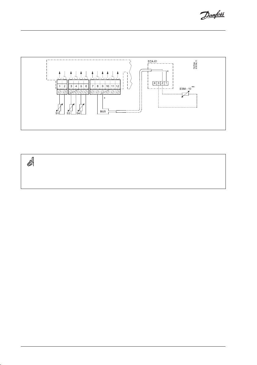
Connecting the temperature sensors and the ECL BUS
Terminal Description Ty pe (recomm.)
1 and 2 S1 Outdoor temperature sensor ESMT
3 and 4 S3 Flow temperature sensor* ESM-11 / ESMC / ESMU
5 and 6 S4 Return temperature sensor ESM-11 / ESMC / ESMU
7 and 8 S2 Room temperature sensor ESM-10
8 and 9 ECL BUS, connections for room panel /
remote control
10 Not to be used
11 and 12 Ext. override
*
The sensor must always be connected in order to have the desired functionality. If the sensor is
not connected or the cable is short-circuited, the motorized control valve closes (safety function).
ECA 61
Wire cross section for sensor connections: 0.4 - 0.75 mm
2
Total cable length: Max. 125 m (all sensors incl. the ECL BUS)
Cable lengths of more than 125 m may cause noise sensibility (EMC).
38 | © Danfoss | 2021.01
AQ188586469712en-010801
Page 39

Installation
How to identify your system type
The ECL Comfort controller is a universal controller that can be used for various systems.
Based on the shown standard systems, it is possible to configure additional systems.
In this section you find the most frequently used systems. If your system is not quite as
shown below, find the diagram which has the best resemblance with your system and
make your own combinations.
Heating system 1: District heating circuit with heat exchanger
Heating system 2: District heating circuit with direct connection
Danfoss
87H2161.10
AQ188586469712en-010801 © Danfoss | 2021.01 | 39
Page 40

Installation
Heating system 3: Boiler-based heating circuit
40 | © Danfoss | 2021.01
AQ188586469712en-010801
Page 41

Installation
Adapting the ECL Comfort 110 controller
When you switch on the controller the first time, it will ask you to choose language
(default language is English).
Language
English
Choose your language.
Accept and go to the next menu.
When the language is chosen, the controller will ask for date and time setting.
Date - time
dd-mm-yy hh:mm
Set day (dd), month (mm), year (yy), hour (hh), and minuts (mm).
Change values.
Accept the chosen time and date.
When the language has been chosen, and date and time have been set, the controller
will ask for application type.
Application
Type ???
Choose application type.
2 sec.
Start the chosen application.
Go to the ‘Maintenance’ part for further setup of your controller.
AQ188586469712en-010801 © Danfoss | 2021.01 | 41
Page 42

Installation
Manual control
Select control mode.
Mode COMFORT<
Wednesday
5 sec.
Go to manual mode.
Actuator M1 is opening (
Actuator M1 is closing ( )
Pump P1 is ON ( )
)
Manual mode
Valve STOP
Manual mode
Pump P1 is OFF (
Select control mode.
)
Pump ON
Mode MANUAL<
Wednesday
Manual mode should only be used for maintenance purposes. In manual mode all control
and safety functions are deactivated!
42 | © Danfoss | 2021.01
AQ188586469712en-010801
Page 43

Installation
Placing the temperature sensors
It is important that the sensors are mounted in the correct position in your system.
The temperature sensor mentioned below are sensors used for the ECL Comfort series
which not all will be needed for your application!
Outdoor temperature sensor (ESMT)
The outdoor sensor should be mounted on that side of the building where it is less
likely to be exposed to direct sunshine. It should not be placed close to doors, windows
or air outlets.
Flow temperature sensor (ESMU, ESM-11 or ESMC)
Place the sensor max. 15 cm from the mixing point. In systems with heat exchanger,
Danfoss recommends that the ESMU-type to be inserted into the exchanger flow outlet.
Make sure that the surface of the pipe is clean and even where the sensor is mounted.
Return temperature sensor (ESMU, ESM-11 or ESMC)
The return sensor should always be placed in / on a pipe with return water flow.
Room temperature sensor (ESM-10 or ECA 61 remote control)
Place the room sensor in the room where the temperature is to be controlled. Do not
place it on outer walls or close to radiators, windows or doors.
DHW temperature sensor (ESMU or ESMB-12)
Place the DHW temperature sensor according to the manufacturer’s specification.
Boiler temperature sensor (ESMU, ESM-11 or ESMC)
Place the sensor according to the boiler manufacturer’s specification.
Flow / air duct temperature sensor (ESM-11, ESMB-12, ESMC or ESMU types)
Place the sensor so that it measures a representative temperature.
Surface temperature sensor (ESMB-12)
Place the sensor in the surface of the floor.
Valid for ESM-11: Do not move the sensor after it has been fastened in order to avoid damage
to the sensor element.
AQ188586469712en-010801 © Danfoss | 2021.01 | 43
Page 44
Installation
Connecting the room panel / remote control
* Connect ECL terminal 9 to 1 and terminal 8 to 2.
The ECA 61 is activated by the setting in line 7010.
The ECA 61 is powered by the ECL BUS which means that the BUS must be active.
The BUS is activated by setting the controller address to 15 (line 7199).
44 | © Danfoss | 2021.01
AQ188586469712en-010801
Page 45

Checklist, electrical connections
Is the ECL Comfort controller ready for use?
Make sure that the correct power supply is connected to terminals 21 (Live)
and 20 (Neutral).
Check that the required controlled units (actuator, pump etc.) are connected
to the correct terminals.
Check that all sensors are connected to the correct terminals.
Switch on the power.
Choose manual operation as controller mode.
Check that valves open and close, and that required controlled units (pump
etc.) start and stop when operated manually.
Check that the temperatures shown in the display match the actual sensors.
AQ188586469712en-010801 © Danfoss | 2021.01 | 45
Page 46

Frequently asked questions
The time shown in the display is one hour off?
See the daylight saving time changeover in line 7198.
The time shown in the display is not correct?
The internal clock may have been reset, if there has been a power break for more than 36
hours. Set time and date. See line 1000.
What does the symbol mean?
The flow temperature is under influence of room temperature limitation, return
temperature limitation, boost, ramping, heating cut-out, DHW priority etc.
The room temperature is too low?
Make sure that the radiator thermostats do not limit the room temperature. If you still
cannot obtain the desired room temperature by adjusting the radiator thermostats, the
flow temperature is too low. Increase the desired room temperature (line 3000). If this
does not help, adjust the heat curve / desired temperature (line 2000).
The room temperature is too high during setback periods?
Make sure that the min. flow temperature limitation is not too high. See line 2177.
The temperature is unstable?
• Check that the flow temperature sensor is correctly connected and in the right place.
• If the controller has a room temperature signal (line 3000), check that the Gain is not
too high.
• Adjust the control parameters (line 6000).
The controller does not operate and the control valve is closed?
• Check that the flow temperature sensor is measuring the correct value, see ‘Daily use’.
• Check the influence from other measured temperatures ( ).
How to restore the factory settings?
See line 7600.
What does P and PI control mean?
P control: Proportional control.
By using a P control, the controller will change the flow temperature proportional to the
difference between a desired and an actual temperature, e.g. a room temperature.
A P control will always have an offset which not will disappear over time.
PI control: Proportional and Integrating control.
A PI control does the same as a P control, but the offset will disappear over time.
A long ‘Intgr. time’ will give a slow but stable control, and a short ‘Intgr. time’ will result in
a fast control but with a higher risk of oscillations.
46 | © Danfoss | 2021.01
AQ188586469712en-010801
Page 47

Definitions
Comfort operation
Normal temperature in the system controlled by the schedule. During heating the flow
temperature in the system is higher to maintain the desired room temperature. During
cooling the flow temperature in the system is lower to maintain the desired room
temperature.
Comfort temperature
Temperature maintained in the heating / DHW circuit during comfort periods.
Desired flow temperature
Temperature calculated by the controller on basis of the outdoor temperature and
influences from the room and / or return temperatures. This temperature is used as a
reference for the control.
Desired room temperature
Temperature which is set as the desired room temperature. The temperature can only be
controlled by the ECL Comfort controller if a room temperature sensor is installed.
If a sensor is not installed, the set desired room temperature however still influences the
flow temperature.
In both cases the room temperature in each room is typically controlled by radiator
thermostats / valves.
Desired temperature
Temperature based on a setting or a controller calculation.
DHW circuit
The circuit for heating the domestic hot water (DHW).
Factory settings
Settings stored in the controller to simplify the setup of your controller the first time.
Flow / DHW temperature
Temperature measured in the flow at any time.
Heating circuit
The circuit for heating the room / building.
Heat curve
A curve showing the relationship between actual outdoor temperature and required
flow temperature.
AQ188586469712en-010801 © Danfoss | 2021.01 | 47
Page 48

Definitions
Limitation temperature
Temperature that influences the desired flow / balance temperature.
Pt 1000 sensor
All sensors used with the ECL Comfort controller are based on the Pt 1000 type. The
resistance is 1000 ohm at 0 °C and it changes with approx. 3.9 ohm / degree.
Optimization
The controller optimizes the start / stop time of the scheduled temperature periods.
Based on the outdoor temperature, the controller automatically calculates when to start
/ stop in order to reach the comfort temperature at the set time. The lower the outdoor
temperature, the earlier the start time. During optimization the comfort / setback
symbol will blink.
Return temperature
The temperature measured in the return can influence the desired flow temperature.
Room temperature sensor
Temperature sensor placed in the room (reference room, typically the living room) where
the temperature is to be controlled.
Room temperature
Temperature measured by the room temperature sensor, room panel or remote
control. The room temperature can only be controlled directly if a room temperature is
measured. The room temperature can influence the desired flow temperature.
Schedule
Schedule for periods with comfort and setback temperatures. The schedule can be made
individually for each week day and it consists of 2 comfort periods per day.
Setback temperature
Temperature maintained in the heating / DHW circuit during setback temperature
periods.
Time bar
The time bars illustrate scheduled periods with comfort temperature.
Weather compensation
Flow temperature control based on the outdoor temperature. The control is related to a
user-defined heat curve.
The definitions apply to the Comfort 110 series. Consequently, you might come across
expressions that are not mentioned in your guide.
48 | © Danfoss | 2021.01
AQ188586469712en-010801
Page 49

AQ188586469712en-010801 © Danfoss | 2021.01 | 49
Page 50

50 | © Danfoss | 2021.01
AQ188586469712en-010801
Page 51

Disposal note
This symbol on the product indicates that it may not be disposed of as
household waste.
It must be handed over to the applicable take-back scheme for the
recycling of electrical and electronic equipment.
• Dispose of the product through channels provided for this purpose.
• Comply with all local and currently applicable laws and regulations.
AQ188586469712en-010801 © Danfoss | 2021.01 | 51
Page 52

!
52 | © Danfoss | DHS-SMDT/DK | 2021.01
*087R9781*
AQ188586469712en-010801
 Loading...