

Page 1
ECL Comfort 100M
User’s Guide and Installation
ECL Comfort 100M
User’s Guide and Installation
*087R9728*
*vi7ab402*
2004.05
*087R9728*
*vi7ab402*
2004.05
Page 2

Table of contents
Page No.
User’s Guide
Temperature setting
Temperature reduction
Installation and maintenance
Table of contents
Page No.
User’s Guide
Temperature setting
Temperature reduction
Installation and maintenance
Page 3

User’s Guide
Before you start
Save energy - save money - improve your
comfort temperature
The ECL Comfort controller is designed by Danfoss for the
The advantages of the ECL Comfort controller system are
the security of your heating control and the op ti mum use
while you are out or asleep save heating costs.
The temperature programming provides comfort and
the au to mat ic pump motion program protects against
Time control of the ECL Comfort 100M controller
When an analog clock is mounted the controller can
This ensures comfortable temperatures when you are at
while you are out.
Page 4
Operating the controller
1
8
1
2
6
1
8
1
2
6
1
8
1
2
6
1
8
1
2
6
1
8
1
2
6
1
8
1
2
6
12
3
6
9
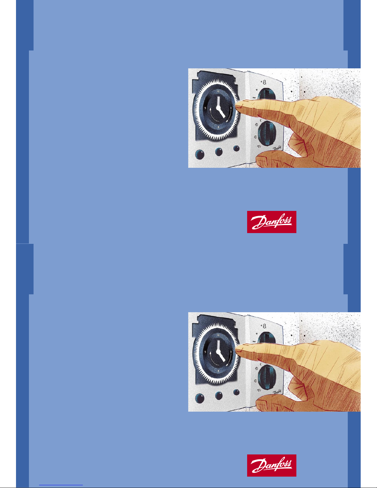
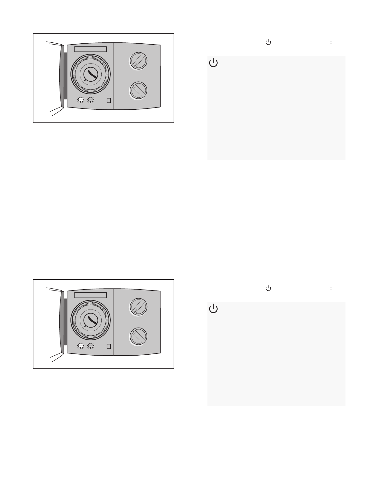
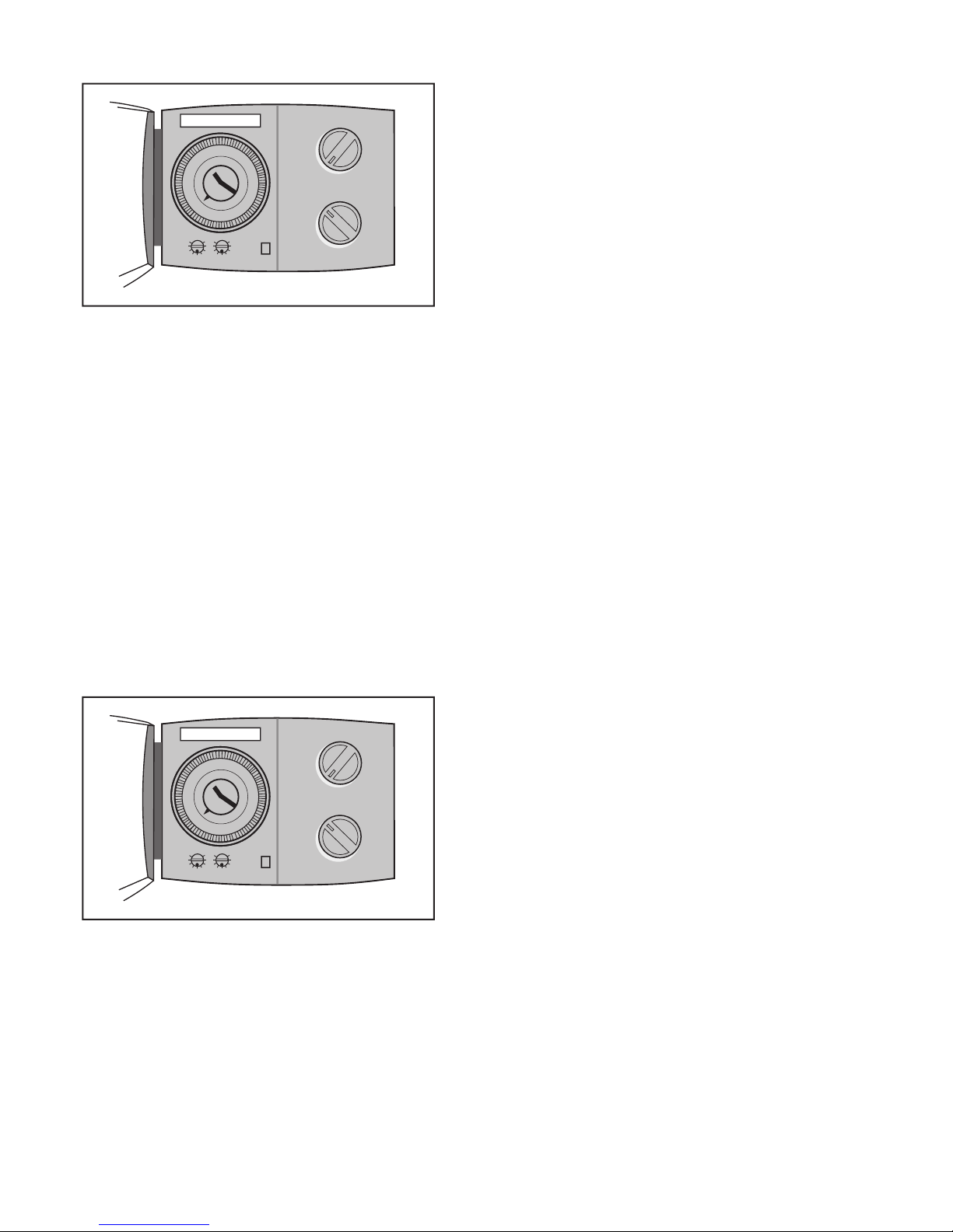
Clock (optional)
Setting the clock
Turn the minute hand to set the actual week day (7-day clock)
You will move the entire outer ring of the clock with its sliders,
just by turn ing the minute hand. Turn the minute hand until
the white ar row points at the actual week day and hour in the
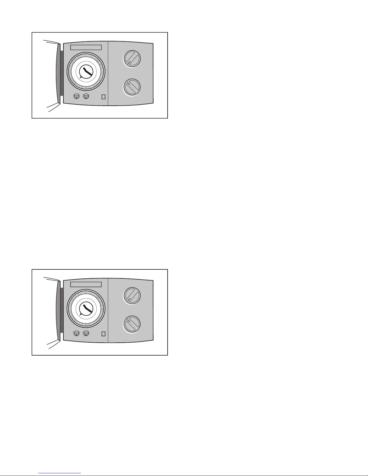
Summer time setting
Individual comfort and reduced
tem per a ture periods
temperature or reduced temperature. Look at the week
the slid ers to point outwards, you set the heat ing sys tem to
Setting the clock
Operating the controller
1
8
1
2
6
1
8
1
2
6
1
8
1
2
6
1
8
1
2
6
1
8
1
2
6
1
8
1
2
6
12
3
6
9
Clock (optional)
Setting the clock
Turn the minute hand to set the actual week day (7-day clock)
You will move the entire outer ring of the clock with its sliders,
just by turn ing the minute hand. Turn the minute hand until
the white ar row points at the actual week day and hour in the
Summer time setting
Individual comfort and reduced
tem per a ture periods
temperature or reduced temperature. Look at the week
the slid ers to point outwards, you set the heat ing sys tem to
Setting the clock
Page 5
What do the symbols mean?
Controller mode
1
8
1
2
6
1
8
1
2
6
1
8
1
2
6
1
8
1
2
6
1
8
1
2
6
1
8
1
2
6
12
3
6
9
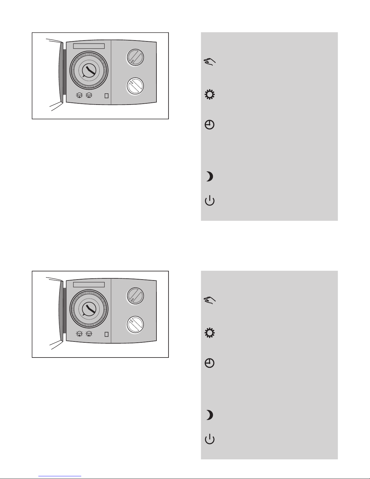
Used only at maintenance
The system protection against frost is
The day plan
work or a late-night party.
Automatic operation.
This is the normal mode.
The tem per a ture is
The temperature is
The day plan
Heating is stopped. The system is
What do the symbols mean?
Controller mode
1
8
1
2
6
1
8
1
2
6
1
8
1
2
6
1
8
1
2
6
1
8
1
2
6
1
8
1
2
6
12
3
6
9
Used only at maintenance
The system protection against frost is
The day plan
work or a late-night party.
Automatic operation.
This is the normal mode.
The tem per a ture is
The temperature is
The day plan
Heating is stopped. The system is
Page 6
Adjustments
If the wanted comfort temperature is not reached?
Make sure that the radiator thermostat/valve is fully open in the
The rooms seem to be too cold?
Before adjusting the comfort temperature on the controller it
If you are not able to obtain the desired temperature by these
value.
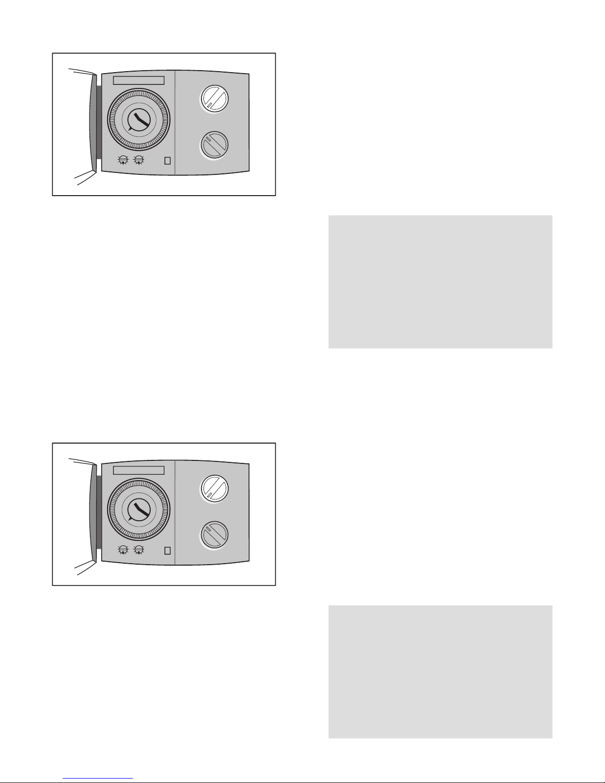
Temperature setting without room sensor
(parallel displacement of the heat curve)
temperature. This cor re sponds approx. to a possible change
Temperature setting with room sensor
temperature setting button will correspond to a room
temperature of 20 °C. The room temperature can be set in a
Temperature setting
1
8
1
2
6
1
8
1
2
6
1
8
1
2
6
1
8
1
2
6
1
8
1
2
6
1
8
1
2
6
12
3
6
9
Adjustments
If the wanted comfort temperature is not reached?
Make sure that the radiator thermostat/valve is fully open in the
The rooms seem to be too cold?
Before adjusting the comfort temperature on the controller it
If you are not able to obtain the desired temperature by these
value.
Temperature setting without room sensor
(parallel displacement of the heat curve)
temperature. This cor re sponds approx. to a possible change
Temperature setting with room sensor
temperature setting button will correspond to a room
temperature of 20 °C. The room temperature can be set in a
Temperature setting
1
8
1
2
6
1
8
1
2
6
1
8
1
2
6
1
8
1
2
6
1
8
1
2
6
1
8
1
2
6
12
3
6
9
Page 7
Temperature reduction in reduced temperature
mode
You can choose how many degrees you want the fl ow
temperature / room temperature to be decreased in time
Temperature reduction
1
8
1
2
6
1
8
1
2
6
1
8
1
2
6
1
8
1
2
6
1
8
1
2
6
1
8
1
2
6
12
3
6
9
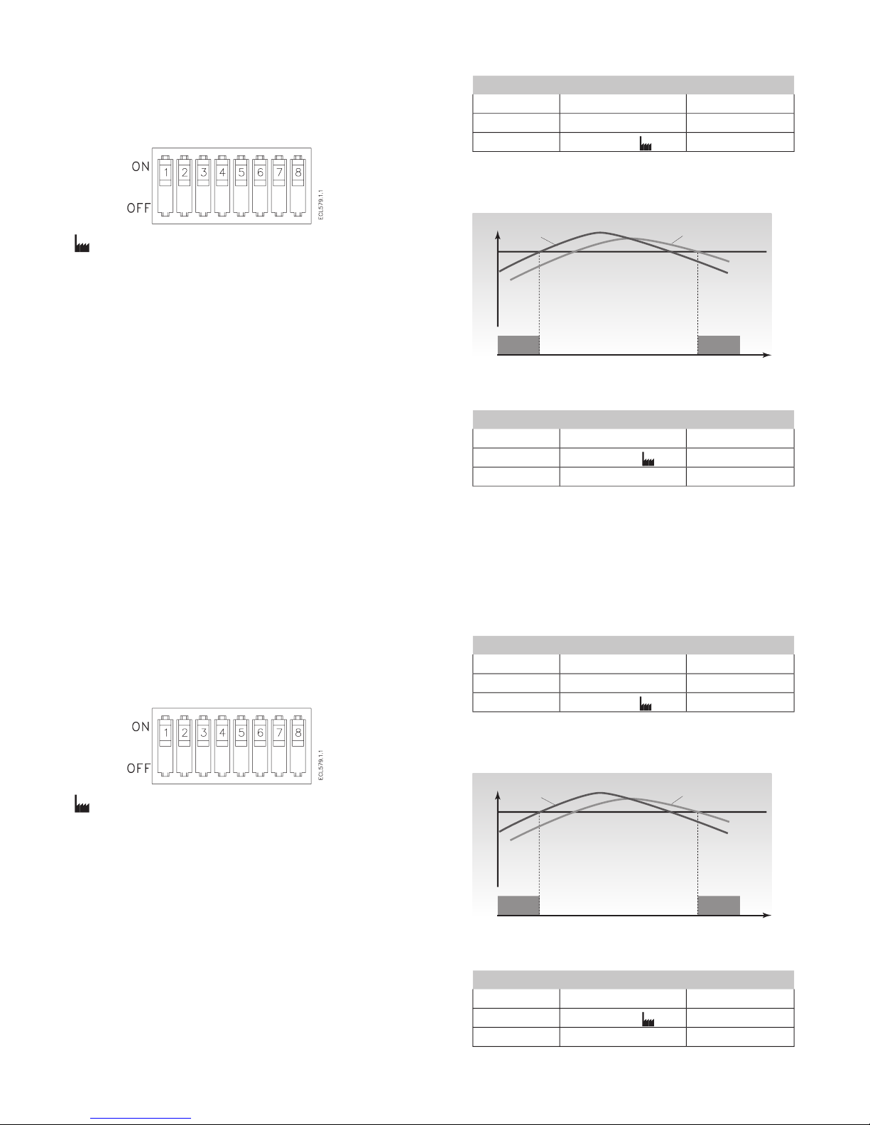
The knob (potentiometer) for the temperature reduction can
(standby),
The heating system is stopped, but still
Without room sensor: The fl ow tem per a ture is
With room sensor: The room tem per a ture is
AUTO
Variable temperature reduction
The temperature reduction is de pend ent
temperature will not be reduced if the outdoor
temperature is below -8 ºC.
Temperature reduction in reduced temperature
mode
You can choose how many degrees you want the fl ow
temperature / room temperature to be decreased in time
Temperature reduction
1
8
1
2
6
1
8
1
2
6
1
8
1
2
6
1
8
1
2
6
1
8
1
2
6
1
8
1
2
6
12
3
6
9
The knob (potentiometer) for the temperature reduction can
(standby),
The heating system is stopped, but still
Without room sensor: The fl ow tem per a ture is
With room sensor: The room tem per a ture is
AUTO
Variable temperature reduction
The temperature reduction is de pend ent
temperature will not be reduced if the outdoor
temperature is below -8 ºC.
Page 8

The heat curve shows the relation between the outdoor
tem per a ture and the fl ow temperature of the heating circuit.
Setting the heat curve
1
8
1
2
6
1
8
1
2
6
1
8
1
2
6
1
8
1
2
6
1
8
1
2
6
1
8
1
2
6
12
3
6
9
-20 -10 0 10 20-30
10
20
30
40
50
60
70
80
90
1.8
1.2
0.6
0.2
2.2
˚C
˚C
You can set the heating curve sl ope in the range from 0.2 to 2. 2. The slope
is factory set to 1.2.
*) Dimensioning temperature depend ing on the temperature normal for
your area.
Page 9
Controller settings on the rear side
To make the controller ready for operation, you must
18 ˚C
Temp
Heatin g
Actual T
out
Accumul ated T
out
Time
Heatin g OFF
Heatin g
The accumulated T
out
The heating cut-out function helps you save energy. Set the
: Factory setting
Your setting
10 ºC
35 ºC
Your setting
18 ºC
Page 10

The running time of the motorized valve is the time it takes
the valve to move from closed to fully open position.
Valve stroke
(mm) X
(sec./mm) =
time.
Your setting
120 sec.
Your setting
45 ºC
90 ºC
Your setting
Thermo actuator
Gear motor
Your
0
built-in
The running time of the motorized valve is the time it takes
the valve to move from closed to fully open position.
Valve stroke
(mm) X
(sec./mm) =
time.
Your setting
120 sec.
Your setting
45 ºC
90 ºC
Your setting
Thermo actuator
Gear motor
Your
0
built-in
4
Page 11

Installation and maintenance
Before you start
Save energy - save money - improve your
comfort temperature
The ECL Comfort controller is designed by Danfoss for
tem per a ture con trol of heating systems.
The ECL Comfort ensures you of the following;
reduce costs and ensure optimum use of energy
resources.
circulation pump against blocking.
Page 12
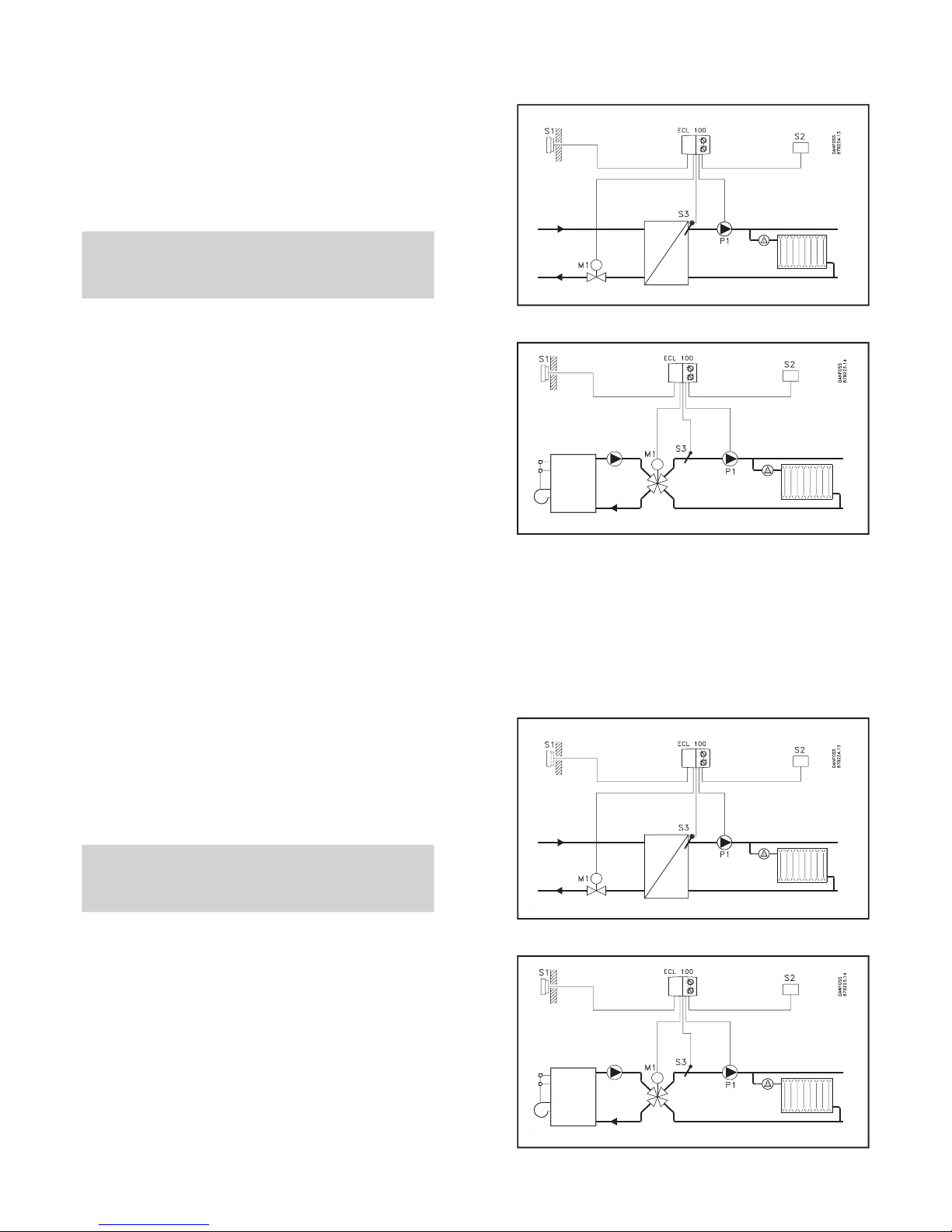
Identifying the system type
The ECL Comfort controller is capable of controlling diff erent
frequently used systems, fi nd the diagram with the best
Identifying the system type
The ECL Comfort controller is capable of controlling diff erent
frequently used systems, fi nd the diagram with the best
Page 13
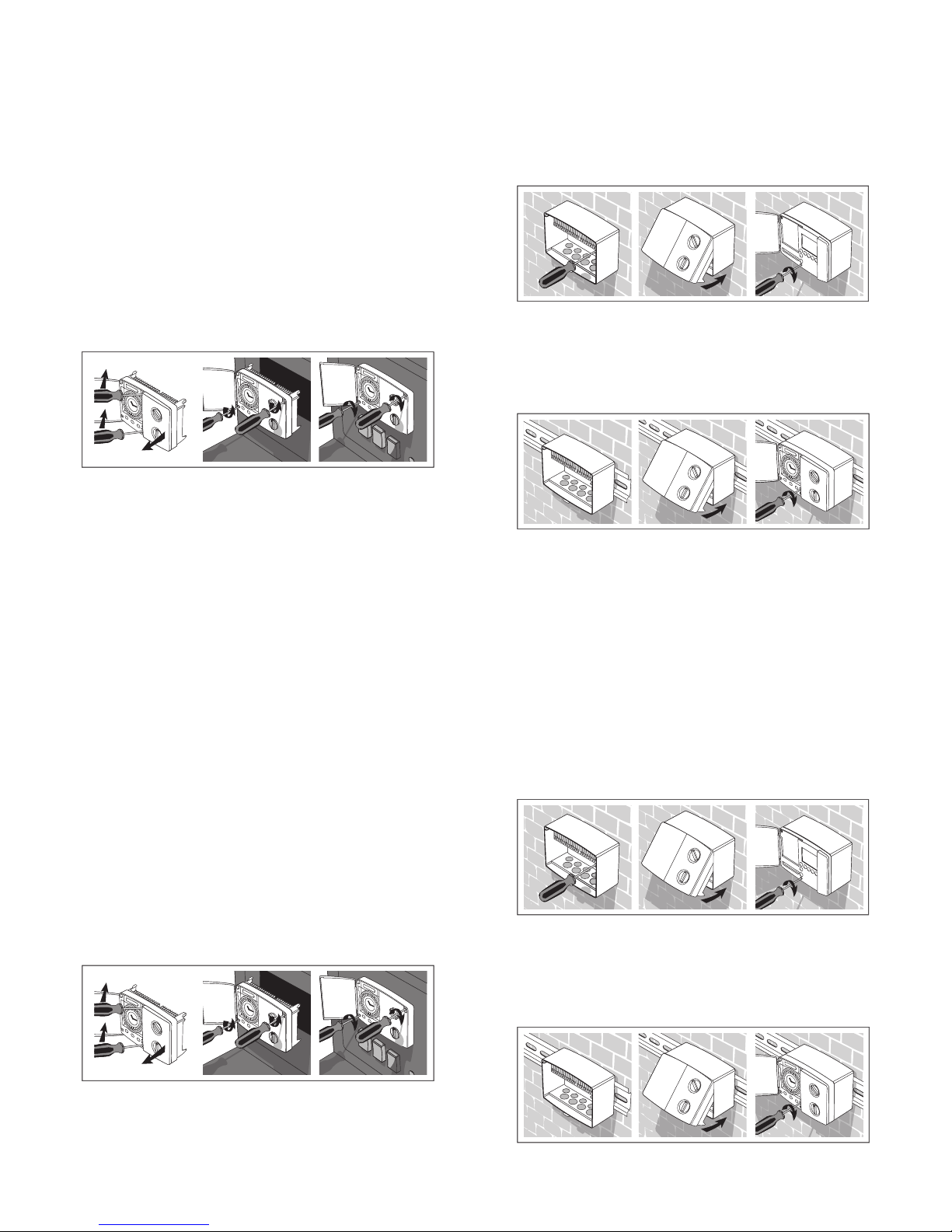
You should mount the ECL Comfort controller for easy
Mounting the controller
Mounting in a panel
The panel plate thickness must not exceed 3 mm. Prepare
fi x it with the two locks which are placed diagonally in the
two corners of the controller.
Mounting on a wall
Mounting on a DIN rail
You should mount the ECL Comfort controller for easy
Mounting the controller
Mounting in a panel
The panel plate thickness must not exceed 3 mm. Prepare
fi x it with the two locks which are placed diagonally in the
two corners of the controller.
Mounting on a wall
Mounting on a DIN rail
Page 14

Outdoor temperature sensor
(ESMT type)
The outdoor sensor should be mounted on the north side
Flow temperature sensor
(ESMU, ESM-11 or ESMC types)
with heat exchanger, Danfoss recommends the ESMU-type
to be inserted into the exchanger fl ow outlet. Make sure
that the surface of the pipe is clean where the sen sor is to be
Placing the tem per a ture sensor types
Room temperature sensor
(ESM-10, ECA 60 and 61 remote controls)
temperature is to be controlled. Do not place it on outside
walls or close to radiators, windows or doors.
Valid for ESM-11: Do not move the sensor after it has been
fastened in order to avoid damage to the sensor element.
Page 15

Electrical connections 230 V a.c.
Electrical connections 24 V a.c.
Terminal
Voltage supply 230 V a.c.
Voltage supply 230 V a.c.
Gear motor - open 0.2 VA 230 V a.c.
4
Gear motor - close
alt.: ABV thermo actuator
0.2 VA 230 V a.c.
heating circuit
4(2)A 230 V a.c.
Terminal
Voltage supply 24 V a.c.
Voltage supply 24 V a.c.
Gear motor - open 1A 24 V a.c.
4
Gear motor - close
alt.: ABV thermo actuator
1A 24 V a.c.
24 V a.c. supply for M1
Relay for circulation
pump
4(2) A 24 V a.c.
24 V a.c. supply for K1
Page 16

Electrical connections - sensors
2
Total cable length: Max. 50 m (sensors and bus).
LED indication
Function test
The LED indicator shows wheth er the 100M is in
Control status
,
the indicator lights.
The fl ow temperature is in the neutral zone
The fl ow temperature
The fl ow
temperature is above the neutral zone. The motor closes
the valve.
The indication does not follow the signals.
Test of controller and sensors
Turn the function switch in position
. After about fi ve
The controller is defective or the fl ow
temperature sen sor is not mount ed.
The number of
The controller is defective.
Terminal
Type
Room sensor (S2) ESM-10
Flow sensor (S3) ESMU/ESM-11/ESMC
Electrical connections - sensors
Total cable length: Max. 50 m (sensors and bus).
LED indication
Function test
The LED indicator shows wheth er the 100M is in
Control status
,
the indicator lights.
The fl ow temperature is in the neutral zone
The fl ow temperature
The fl ow
temperature is above the neutral zone. The motor closes
the valve.
The indication does not follow the signals.
Test of controller and sensors
Turn the function switch in position
. After about fi ve
The controller is defective or the fl ow
temperature sen sor is not mount ed.
The number of
The controller is defective.
Terminal
Type
Room sensor (S2) ESM-10
Flow sensor (S3) ESMU/ESM-11/ESMC
Page 17

Check list
Is the ECL Comfort controller ready for use?
Controller settings on the rear side.
✐
Check list
Is the ECL Comfort controller ready for use?
Controller settings on the rear side.
✐
You can check the turning direction of the
feel ing whether the temperature of the actual pipe
The LED indicator shows whether the 100M is
You can check the turning direction of the
feel ing whether the temperature of the actual pipe
The LED indicator shows whether the 100M is
Page 18

Communication
The ECL Comfort controller can be connected to
Master / slave systems
The controller which is physically connected with the out door
temperature demand can be sent to the master. The master
Communication
The ECL Comfort controller can be connected to
Master / slave systems
The controller which is physically connected with the out door
temperature demand can be sent to the master. The master
Page 19
1
8
1
2
6
1
8
1
2
6
1
8
1
2
6
1
8
1
2
6
1
8
1
2
6
1
8
1
2
6
12
3
6
9
Power back-up for your ECL Comfort controller
To ensure power back-up there is a battery placed above the
Power back-up
1
8
1
2
6
1
8
1
2
6
1
8
1
2
6
1
8
1
2
6
1
8
1
2
6
1
8
1
2
6
12
3
6
9
Power back-up for your ECL Comfort controller
To ensure power back-up there is a battery placed above the
Power back-up
Page 20

The circuit for heating the room/building.
the Pt 1000 ohm type. The resistance is 1000 ohms at 0 °C and
The temperature measured with the room sensor. The room
temperature can be controlled only when the sensor is
Weather compensation
temperature into consideration for heat ing con trol.
This control is based on a user defi nable heat curve which
Defi nitions
Actual flow temperature
The temperature that is measured in the fl ow at any
time.
The temperature maintained in the heating or hot water
Page 21

 Loading...