

Page 1

User’s Guide
ECL 2000
11-99 EY.65.H4.02
Page 2

Page 3

User’s Guide
ECL 2000
Danfoss A/S
EY.65.H4.02
Page 4

ECL 2000
EY.65.H4.02
ii
Danfoss can accept no responsibility for possible errors in catalogues, brochures and other printed material. Danfoss reserves the right to alter its products without notice. This also applies to products already on order provided that such alterations can be made without subsequential changes being necessary in specifications already agreed. All trademarks in
this material are property of the respective companies. Danfoss and the Danfoss logotype are trademarks of Danfoss
A/S. All rights reserved.
This manual replaces the ECL 2000 User’s Guide of April 1999.
Danfoss A/S ID: EY.65.H4.02
DK-6430 Nordborg Date: November 1999
Denmark
Phone: +45 74 88 22 22
Copyright 1999 Danfoss A/S. All Rights Reserved
Page 5

Contents
EY.65.H4.02
iii
TABLE OF CONTENTS
1. INTRODUCTION 1
1.1 What Is In This Guide? 1
1.2 Getting Started With the ECL 2000 1
2. INTRODUCING THE ECL 2000 3
2.1 What is the ECL 2000? 3
2.2 Operating Modes 3
2.3 Circuit Functions 4
2.4 Time Programming 4
2.5 Other Functions 4
3. OPERATING THE ECL 2000 5
3.1 The Front Panel 5
3.2 Front Panel Push-buttons 6
3.3 Display Icons 7
4. DAY-TO-DAY OPERATION 9
4.1 About This Chapter 9
4.2 System Overview 10
4.3 Selecting a Circuit. Viewing Circuit Status 12
4.4 Changing Comfort and Night Setback Temperature Settings 14
4.5 Changing the Operating Mode 15
5. TIME PROGRAMMING 16
5.1 Extending the Comfort or Night Setback Period 16
5.2 Setting the 7-Day Plan 17
5.3 Setting the Holiday Plan 18
6. ENTERING THE ACCESS CODE 20
7. WEATHER COMPENSATION CURVES 21
7.1 Adjusting the Flow Temperature Curve 22
7.2 Adjusting the Return Temperature Curve 23
8. CONFIGURING THE ECL 2000 25
8.1 Starting the ECL 2000 for the First Time 25
8.2 ECL 2000 Types 25
8.3 Selecting an Application 26
8.4 Configuring Inputs and Outputs 27
8.4.1 Operating Configuration Pictures 27
8.4.2 Sensor Inputs 30
8.4.3 LON Inputs 32
8.4.4 Relay Output 33
8.5 Overview of ECL 2000 Applications 34
9. MANUAL OVERRIDE 36
Page 6

Contents
EY.65.H4.02
iv
10. SERVICE SETTINGS 38
10.1 Operating Service Menus 39
10.2 Heat Circuit Functions 41
10.2.1 Building Settings 41
Optimizer 42
10.2.2 Pump/Valve Settings 45
10.2.3 PI Constant Settings 47
10.2.4 Limiter 48
10.3 Hot-water Circuit Functions 51
10.3.1 Hot Water Settings 52
10.3.2 Pump/Valve Settings 56
10.3.3 PI Constant Settings 58
10.3.4 Limiter 59
10.4 Common Functions 62
10.4.1 Set Clock 64
10.4.2 Alarm Status 65
10.4.3 Alarm Setup 66
10.4.4 Log Today, Log Yesterday 67
10.4.5 Override 68
10.4.6 Communication 70
10.4.7 Sensors 71
10.4.8 Degree Days 72
10.4.9 Access Code 72
10.4.10 Energy Consumption 73
10.4.11 Language 74
10.4.12 Version 74
APPENDIX A. DISPLAY CHARTS 75
A.1 Setting the Operating Mode 75
A.2 System Overview. Selecting a Circuit. Viewing Circuit Status 76
A.3 Time Programming 77
A.4 Weather Compensation Curves 78
A.5 Configuring the ECL 2000 79
A.6 Manual Override 80
APPENDIX B. SERVICE MENUS 81
B.1 Heat Circuit Menus 81
B.2 Hot-Water Service Menus 82
B.3 Common Function Menus 83
APPENDIX C. LOG DISPLAYS 87
GLOSSARY 89
REFERENCES 93
INDEX 95
Page 7

Introduction
EY.65.H4.02
1
1. INTRODUCTION
1.1 What Is In This Guide?
This Guide is for the ECL 2000 district heating temperature controller. The purpose
of the Guide is to describe the functionality of the ECL 2000 and to enable users to
operate the controller from the front panel.
Chapter 2-7 provide information regarding the day-to-day usage of the controller.
Chapter 8-10 provide information intended for project and service engineers, for
example about configuring the ECL 2000 and using service menus to modify the setup
of the controller. Appendix A contains a number of charts providing an overview of
the ECL 2000’s display pictures. Appendix B provides a similar listing of the ECL
2000’s service menus. Appendix C provides a list of the data displayed in the ECL
2000’s Log pictures. At the end of the Guide, you find a glossary, a list of references
and an index.
1.2 Getting Started With the ECL 2000
Instructions for installing the ECL 2000 are provided in the ECL 2000 Installation
Guide (ref. [2]). After the controller has been installed, it must be configured. This
step consists of selecting an application (i.e. a system type) and, if the selected
application allows this, configuring inputs and outputs. Instructions for this start on
page 25 of this Guide.
Page 8

Introduction
EY.65.H4.02
2
This page is intentionally left blank
Page 9

Introducing the ECL 2000
EY.65.H4.02
3
2. INTRODUCING THE ECL 2000
2.1 What is the ECL 2000?
The ECL 2000 is a micro-processor based controller used for temperature control and
regulation in district heating systems and for mixing control in boiler systems.
The controller can be used for weather compensation and control in the following
types of systems:
• Two parallel district heating circuits
• Two heat circuits and one hot-water circuit
• Two separate weather compensated heat circuits
• Two heat circuits combined with hot-water tank control.
Two types of ECL 2000 are available with different input/output configurations.
ECL 2000 Type 1 is supplied with 14 pre-programmed applications (i.e. 14 standard
system setups). Type 2 has 17 pre-programmed applications. The ECL 2000’s built-in
applications cover a wide variety of commonly used central heating configurations.
See page 25 for further information.
2.2 Operating Modes
The controller can operate in 4 different modes:
• Automatic
• Comfort
• Night setback
• Stand-by.
In Automatic mode, the controller alternates between two temperature setpoints: comfort and night setback. The flow temperature of a heat circuit and the hot-water temperature are kept at either comfort or night setback temperature, according to a userdefined 7-day plan.
In Comfort mode, flow and hot-water temperatures are maintained at daytime level.
In Night setback mode, the plant is maintained at night setback temperature, which is
normally lower than the comfort temperature.
Note:
The controller can be in night setback mode even during the daytime, for example
over the week-end.
In Stand-by mode, heating is off, but the plant is frost-protected at 6 °C.
Page 10

Introducing the ECL 2000
EY.65.H4.02
4
2.3 Circuit Functions
Heat circuit functionality includes weather compensation of flow temperature according to outdoor temperature, sun intensity and wind velocity, outdoor temperature
dependant return temperature limiting, PI control of valve motors, as well as an
optimizer facility that will save energy by calculating optimum pre-heat and cooling
times for the plant. If a room temperature sensor is fitted, the optimizer is adaptive.
Hot-water circuit facilities include PI control of valve motors, return temperature limiting and an anti-bacteria function.
The ECL 2000 has a built-in timer function with a year clock, which can be used to
switch on and off an external device according to a 7-day, 24-hour program.
2.4 Time Programming
The ECL 2000’s time programming facility lets you set up an individual 7-day, 24hour program for each of the circuits being controlled.
The ‘party function’ allows the ECL 2000 to override the 24-hour program and keep
one or more circuits at comfort temperature for a prolonged period of time, for example until later in the evening than normally. The economy function lets the ECL 2000
keep the plant at night setback temperature longer than normally.
You can also pre-program a holiday period during which the controller will follow a
different 24-hour schedule than under normal conditions.
2.5 Other Functions
The controller includes a Manual Override facility that disables all automatic control,
allowing for manual control of circuit components (pumps and valve motors).
The controller’s alarm system lets you define conditions that will cause an alarm. You
can monitor the alarm status by displaying the controller’s alarm log and one relay
output can be defined as an alarm output.
The ECL 2000 also includes facilities for logging measured data and displaying this
graphically, as well as for calculating degree days.
LON (Local Operating Network) communication is available as an option. This facility enables the ECL 2000 to communicate via LON with other ECL 2000 controllers
and devices such as heatmeters.
Page 11
Operating the ECL 2000
EY.65.H4.02
5
3. OPERATING THE ECL 2000
A few basic principles determine the way the ECL 2000 is operated – these principles
apply to all ECL 2000 functions. This section gives a brief introduction to these principles.
Detailed descriptions of the various ECL 2000 functions are given from page 9. For
an overview of navigating through ECL 2000 pictures, see the charts in Appendix A,
page 75.
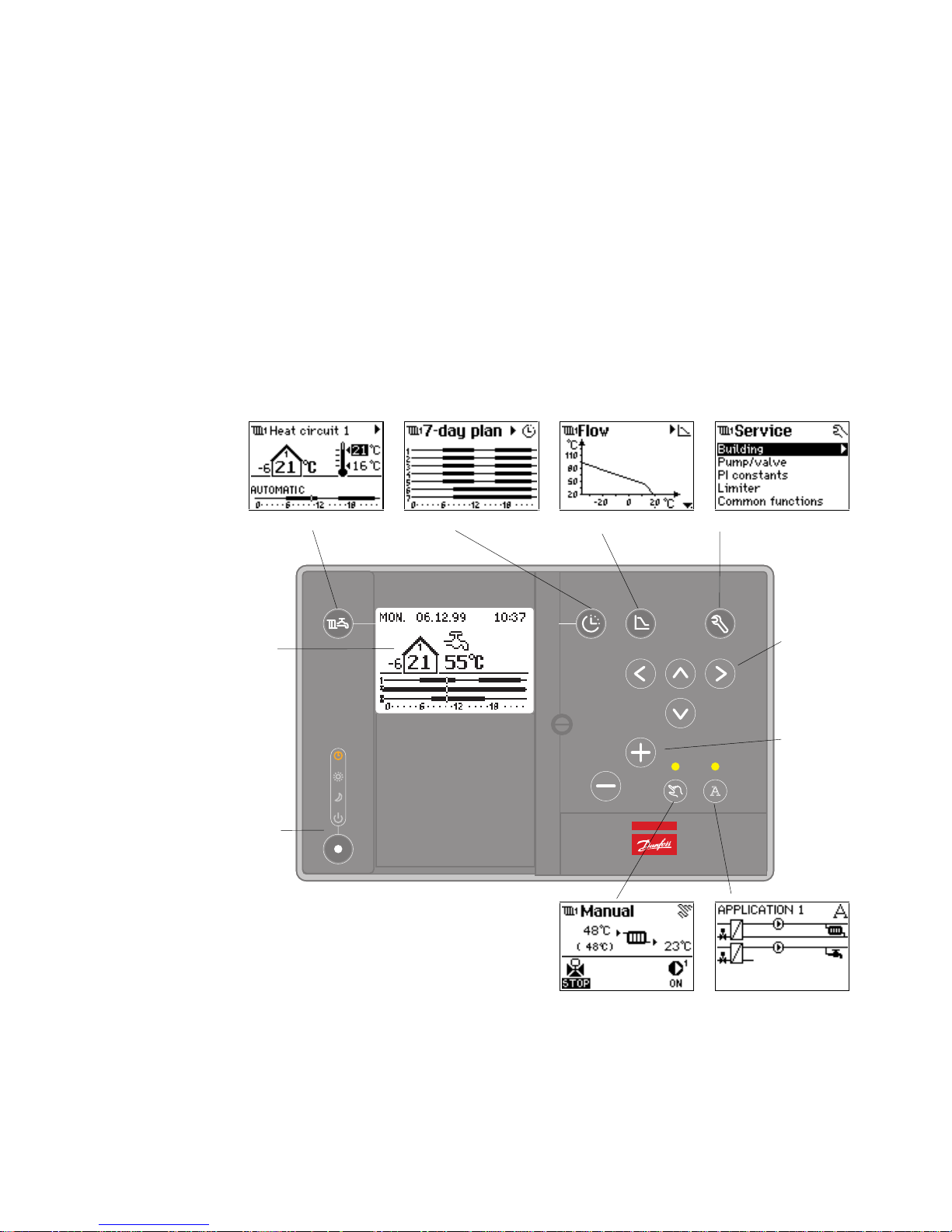
3.1 The Front Panel
Select circuit 7-day plan and holiday
plan
Weather compensation
curves
Service settings
LCD display
Operating mode
Go to next
picture/
Move cursor
Change setting
Manual override Application
Figure 1. ECL 2000 front panel push buttons
Page 12
Operating the ECL 2000
EY.65.H4.02
6
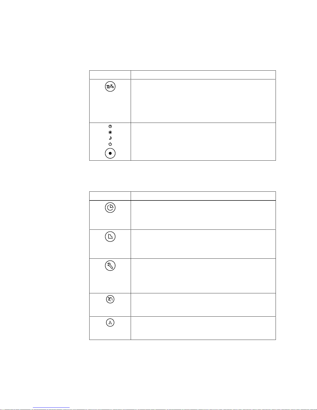
3.2 Front Panel Push-buttons
The following push-buttons operate independently of all other functions:
Push-button Function
Circuit
Selects a circuit, that is, a heat circuit, a hot-water circuit or a timer.
When you press the push-button, the display switches from the System
Overview picture to the picture of the first circuit, to the next circuit,
etc. and finally back to the System Overview again.
See page 12.
Mode
Changes the operating mode of the controller. The ECL 2000 can operate in 4 different modes: Automatic, Comfort, Night setback and Standby.
See page 15.
The function buttons activate 5 main functions: Setting time programs, adjusting
weather compensation curves, changing service settings, operating the plant manually
and selecting an application. These are:
Push-button Function
7-day plan and holiday plan
Lets you modify the controller’s 7-day plan, set up a holiday period and
a 24-hour program to follow during the holiday period.
See page 17.
Weather compensation curves
Allows you to modify the weather compensation curves used by the
ECL 2000 to control flow and return temperatures in a heat circuit.
See page 21.
Service settings
Activates the ECL 2000’s service menus. The service menus allow you
to change settings for the circuits controlled by the ECL 2000 and to
monitor actual values of plant variables.
See page 38.
Manual override
Enables manual operation of individual components in the plant.
See page 36.
Application
Lets you select an application, which is a standard system setup
See page 26.
Page 13
Operating the ECL 2000
EY.65.H4.02
7
Exit The general principle of the ECL 2000 is as follows: Once you have pressed one of
these push-buttons and activated the corresponding function, you exit the function by
pressing the same button once more. There are minor exceptions to this rule – these
are indicated in the appropriate sections of this User’s Guide. When you exit a function, any modifications you have performed are saved.
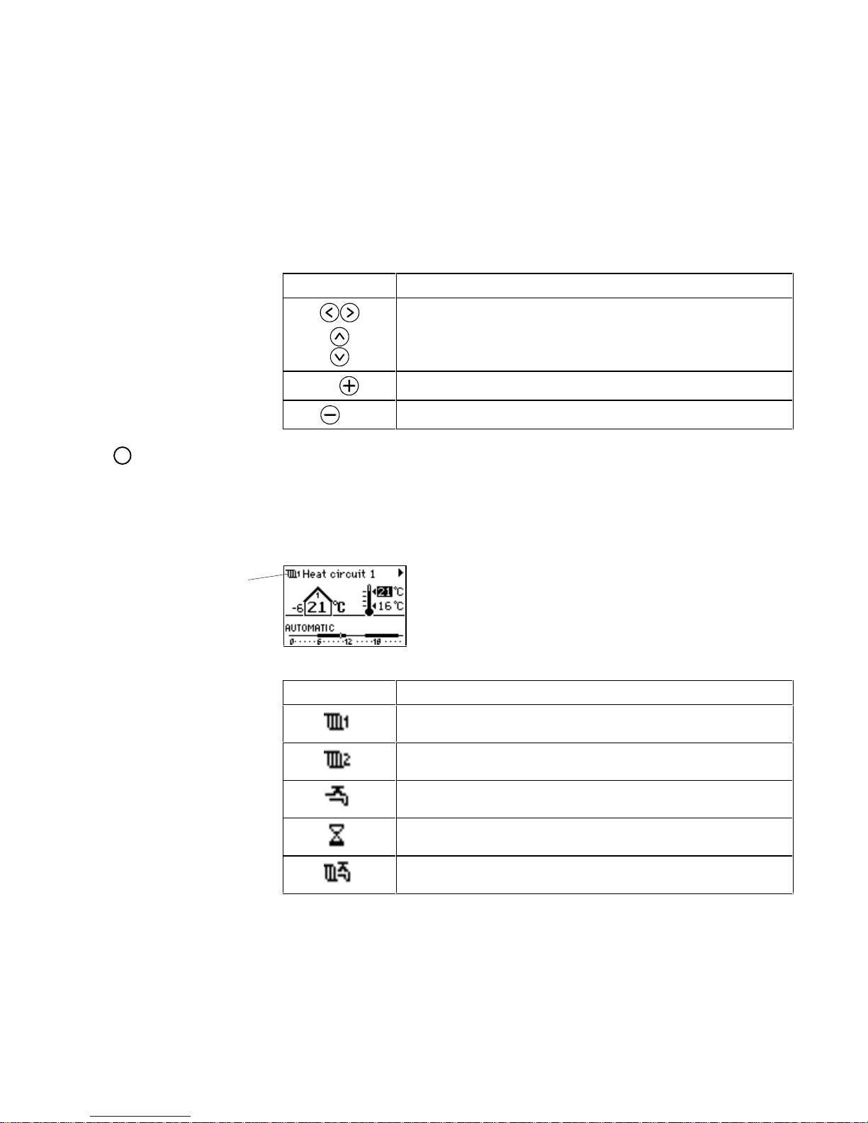
The remaining front panel buttons perform the functions outlined in the table below:
Push-button Function
Change the display to the next/previous picture in a series, for example
in the System Overview or the Circuit Status.
Move the cursor within a picture.
Increases the value of a setting, for example a temperature setpoint.
Reduces the value of a setting.
!
Note:
Before being allowed to modify a setting, you may be prompted to enter an access
code. See page 20 for instructions.
3.3 Display Icons
The ECL 2000’s displays are provided with a number of
icons to help you navigate through the pictures. The
following icons appear in the upper left corner of the
display:
Icon Indicates
Data for heat circuit no. 1 is being displayed.
Data for heat circuit no. 2 is being displayed.
Data for the hot-water circuit is being displayed.
Data for the timer function is being displayed.
Settings concerning al l circuits: Common Functions in service menus.
Icon
Page 14
Operating the ECL 2000
EY.65.H4.02
8
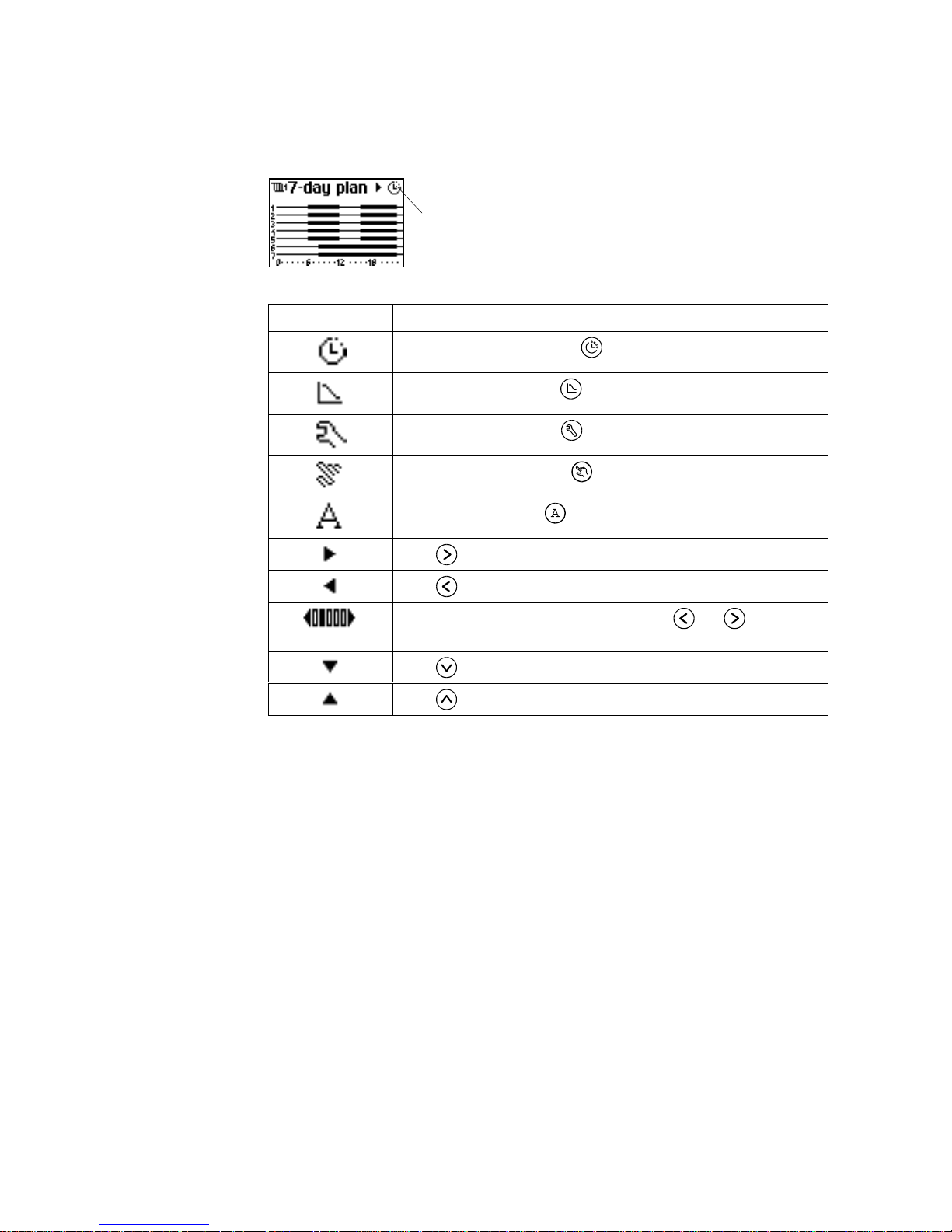
Icons displayed on the right-hand side of the display:
Icon Indicates
Time programming is active – was pressed.
Curve adjusting is active – was pressed.
Service menus are active – was pressed.
Manual operation is active – was pressed.
System setup is active – was pressed.
Press to access next picture.
Press to access previous picture.
Picture no. 2 of 5 is currently displayed. Press and to access
other pictures.
Press to display more settings.
Press to display more settings.
Icon
Page 15

Day-to-Day Operation
EY.65.H4.02
9
4. DAY-TO-DAY OPERATION
4.1 About This Chapter
This chapter is intended for the daily user of the ECL 2000. It describes the functions
which are used during normal day-to-day operation of the ECL 2000. Instructions are
provided for:
• Getting an overview of the plant and looking at individual circuits in the system
• Setting the ECL 2000’s operating mode
• Viewing status information
• Changing temperature setpoints.
Page 16
Day-to-Day Operation
EY.65.H4.02
10
4.2 System Overview
The System Overview is the ECL 2000’s main picture. When the ECL 2000 is
powered on, the System Overview appears in the display after the self-test has been
completed
1
. During normal operation, whenever no front panel push-button is
operated for a 10 minute period, the ECL 2000 automatically reverts to the System
Overview.
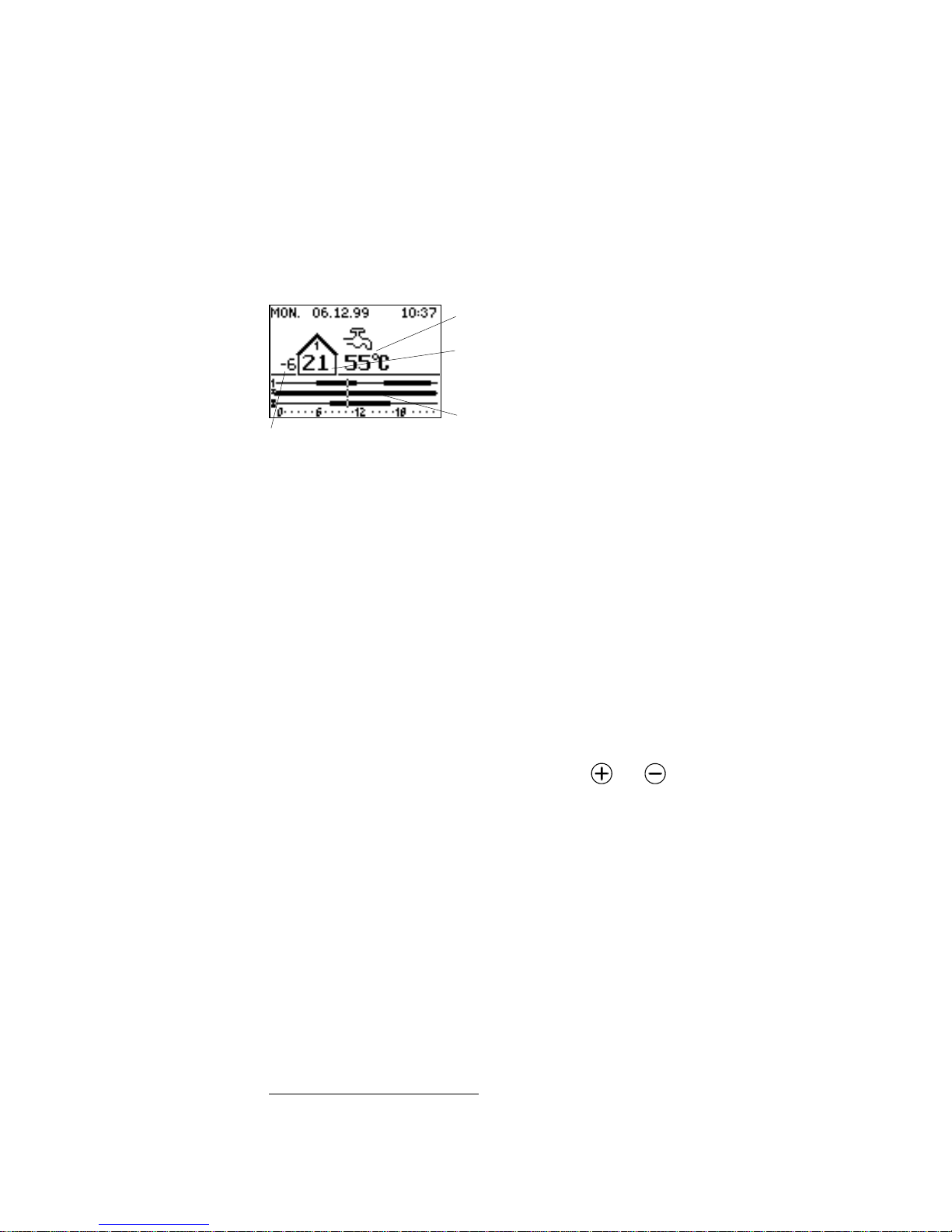
System Overview
Actual outdoor temperature
Actual hot-water temperature
Room temperature. If the plant has more than one heat
circuit, the room temperature is displayed individually
for each heat circuit.
24-hour program for all circuits. This 24-hour program
indicates that heat circuit 1 should be maintained at
comfort temperature from 06:00 to 12:00 and from
16:00 to 23:00. Outside these periods, the circuit is
maintained at night setback temperature. The hot water
is kept at comfort temperature constantly.
The System Overview shows the total setup of the plant. This means that the picture
looks slightly different, according to the application that was selected when the
controller was configured.
Timer
The heating system in this example consists of one heat circuit and one hot-water
circuit. In addition to these, the system also includes a timer, which you can see from
third line of the 24-hour program. When this function is enabled, a set of outputs on
the controller is used to switch on and off some external device, that is, the ECL 2000
is used as a timer to control this other device. See also page 33.
Display contrast
If the temperature in the room where the ECL 2000 is installed is very high, this may
affect the contrast of the controller’s LCD display.
1. In the System Overview picture, use
and to adjust the display
contrast.
1
See page 25 for information on what to do when powering on the ECL 2000 for the first time.
Page 17
Day-to-Day Operation
EY.65.H4.02
11
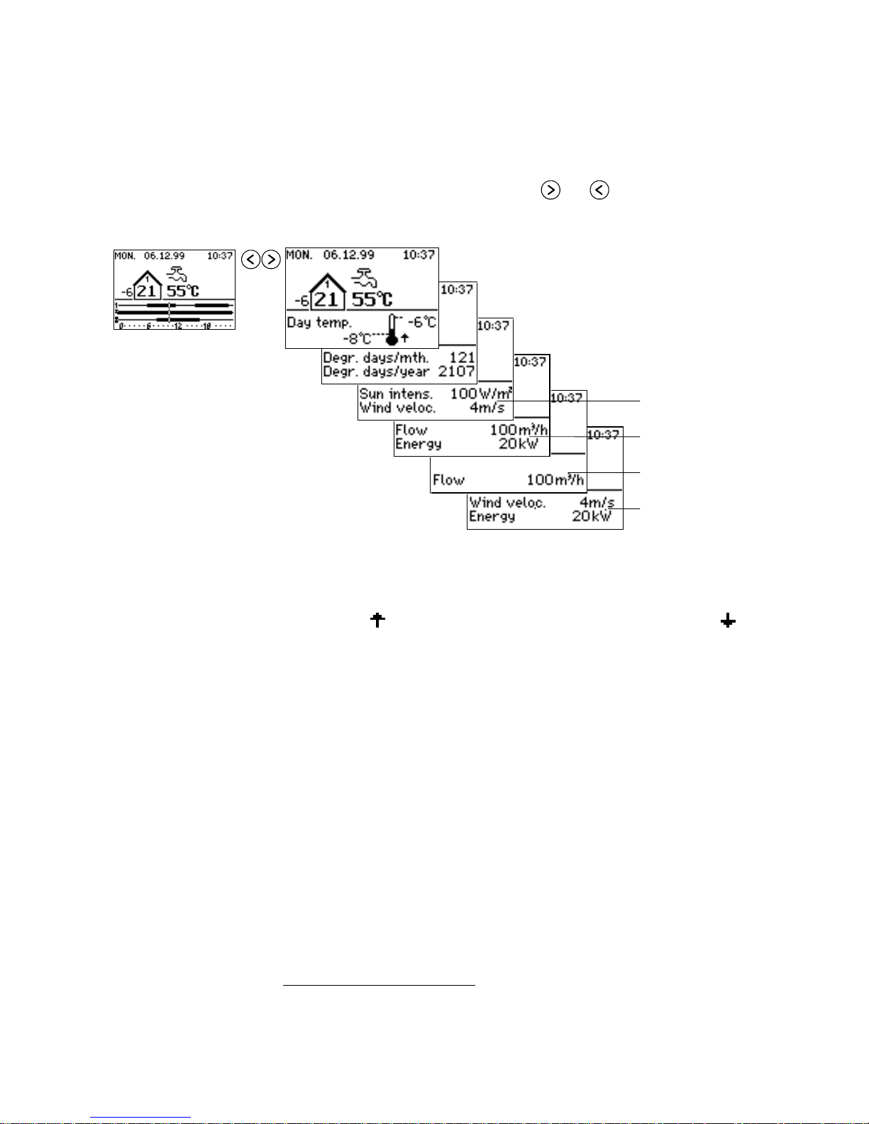
System status
To view status information for the entire plant:
1. From the System Overview, use
and
to display further information.
See illustration below.
Depending on the selected application and the sensors connected to the system, the
following status information can be available:
2
Day temperature
This picture displays the highest and lowest outdoor temperature measured since
midnight. The
symbol indicates that the actual temperature is rising. A indicates
that the temperature is falling.
Degree days
The number of degree days calculated since the first day of the current month and the
number of degree days calculated since the change of season.
3
The following status information is only available when the appropriate sensors are
connected to the ECL 2000:
Sun intensity
Actual value of sun intensity.
Wind velocity
Actual wind velocity.
Water Flow
Actual value of water flow.
Energy
Actual value of energy consumption.
Other
Actual reading from a user-defined sensor connected to the controller.
2
See page 27 for information on configuring the ECL 2000’s sensor inputs and LON inputs
3
By default, the season for degree day calculation starts on 1. June
Sensor S8 and S9
Sensor S10 and S11
(ECL 2000 Type 2 only)
Sensor L1 and L2
(LON option installed)
Sensor L3 and L4
(LON option installed)
Page 18
Day-to-Day Operation
EY.65.H4.02
12
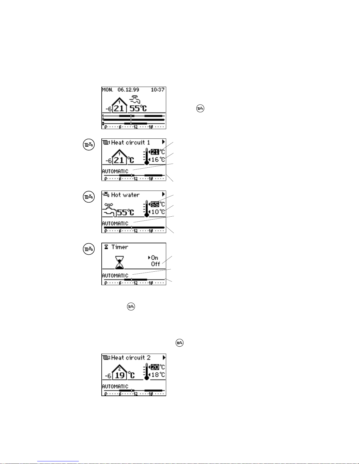
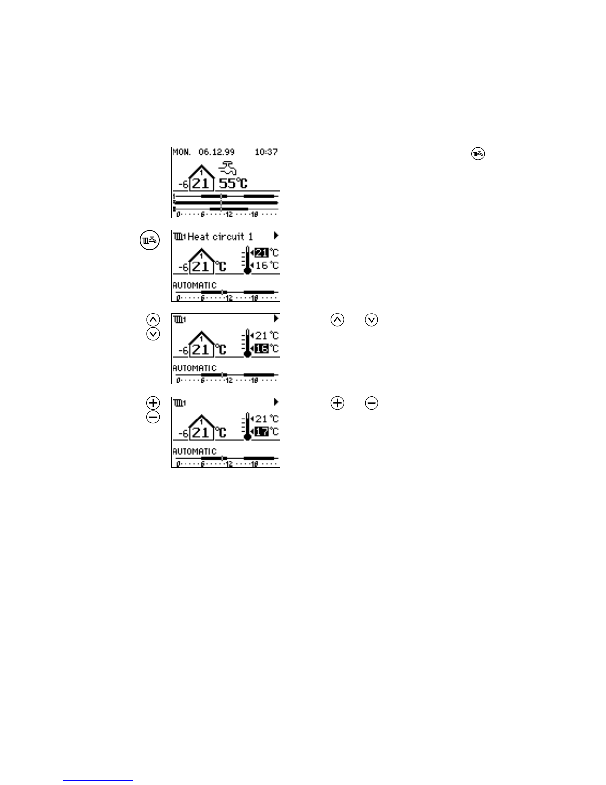
4.3 Selecting a Circuit. Viewing Circuit Status
This section tells you how to select an individual circuit in the plant and display status
data for this circuit.
In the System Overview picture or in one of the System
Status pictures (see page 10-11):
1. Press
to display the next circuit in the plant.
Comfort temperature setpoint
Night setback temperature setpoint
Operating mode of the circuit: Automatic, Comfort,
Night setback or Stand-by. See page 3
24-hour program
Comfort temperature setpoint
Night setback temperature setpoint
Operating mode of the circuit: Automatic, Comfort,
Night setback or Stand-by
24-hour program
Current status of timer
Operating mode of the timer
24-hour program
To return to the System Overview:
2. Press
again.
Whenever you wish to change the setup or view data for one circuit separately, you
start by selecting the circuit. This function is active in most of the ECL 2000’s pictures. For example, while setting the operating mode for one circuit, you can switch
to the next circuit by pressing
.
Several of the ECL 2000’s built-in applications include
two heat circuits. When a second heat circuit is part of
the application, this circuit has a picture associated with
it that is very similar to the picture for Heat circuit 1.
Page 19
Day-to-Day Operation
EY.65.H4.02
13
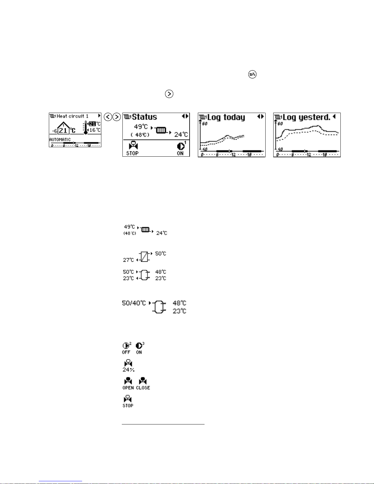
View Status
To view status information for one circuit:
1. In the System Overview picture, press
until you see the picture of the
appropriate circuit.
2. Press
to display status information for the circuit, once more to display
today’s log, and again to display yesterday’s log.
The status of individual
components of the selected circuit. The symbols used in the picture are
explained below.
Today’s log. The fully
drawn curve shows variations in flow temperature.
The dotted curve indicates
the return temperature.
4
Yesterday’s log. The fully
drawn curve shows the
flow temperature, the
dotted curve shows the
return temperature.
4
Temperature readings
The following temperature information is available in Status pictures, depending on
the selected application and the type of circuit:
5
Actual (49 °C) and reference flow temperature (calculated, 48 °C), return temperature (24 °C) for a radiator
heating system.
Primary return temperature and secondary flow temperature for a circuit that includes a heat exchanger.
Charging (50 °C) and return temperature (23 °C), upper
tank temperature (48 °C) and lower tank temperature
(23 °C) for a circuit that includes a hot-water storage
tank.
Flow temperature (50/40 °C) measured by two sensors
in a circuit that includes a hot-water storage tank.
Pump and valve status
The following pump and valve information can be available in Status pictures, depending on the application and the type of circuit.
Pump status: Pump no. 2 is currently off while pump
no. 3 is operating.
Valve status: Valve 24 % open.
Valve motor status: Valve moving in the open-
ing/closing direction, respectively.
Valve motor status: Valve is not moving.
4
See Appendix C, page 87 for a complete list of the data displayed in Log pictures
5
A blank reading indicates that the sensor is not connected or that there is a sensor error
Page 20
Day-to-Day Operation
EY.65.H4.02
14
4.4 Changing Comfort and Night Setback Temperature Settings
This page tells you how to change the comfort and night setback temperature settings
for a heat circuit or a hot-water service.
1. In the System Overview picture, press to dis-
play the picture of the desired circuit.
In the Circuit picture in this example, the comfort temperature is highlighted, indicating that this setting is
selected.
2. Use and to select the temperature setting
that should be changed – the comfort temperature
or the night setback temperature.
3. Use and to change the temperature setting.
Page 21
Day-to-Day Operation
EY.65.H4.02
15
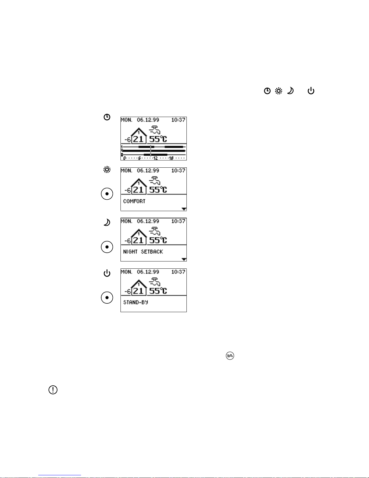
4.5 Changing the Operating Mode
Changing the operating
mode for all circuits
The ECL 2000 can operate in 4 modes. Use the Mode push-button on the front panel
to change the controller’s operating mode.
Above the Mode push-button, there are 4 LED symbols:
, ,
and
. When
you select an operating mode, the symbol corresponding to the selected mode lights
up.
Automatic
The controller switches between comfort and night setback temperature as specified in the 7-day plan.
Page 17 tells you how to modify the plan.
Comfort
The controller maintains comfort temperature for all
circuits.
Night setback
The controller maintains night setback temperature constantly in all circuits.
Stand-by
Temperature control is stopped but the system is frostprotected at 6 °C.
By pressing the Mode button once more, all three circuits are set in Automatic mode.
Changing the operating
mode for one circuit
Alternatively, you can change the operating mode for each of the system’s circuits
individually:
1. In the System Overview, press
to select the circuit you wish to work
with.
2. Use the Mode push-button to select the desired operating mode.
Note:
If the system includes a timer circuit, this circuit will be set in Night Setback mode
when Stand-by is selected, that is, the timer output will be constantly off.
Page 22
Time Programming
EY.65.H4.02
16
5. TIME PROGRAMMING
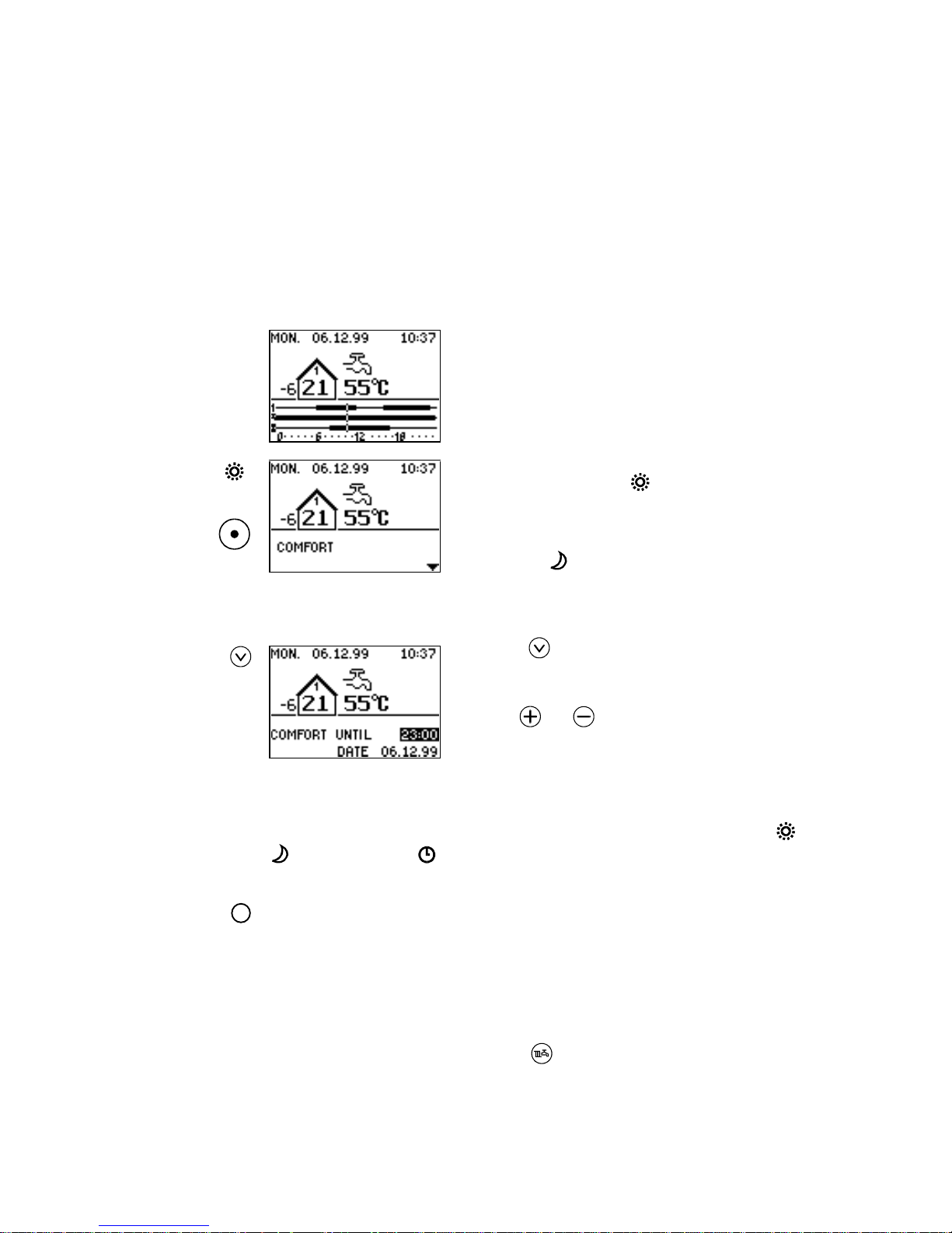
5.1 Extending the Comfort or Night Setback Period
The ECL 2000 offers two functions allowing you to override the controller’s 24-hour
program. The party function extends the comfort temperature period while the
economy function extends the night setback period.
You can extend the comfort or night setback period for
the whole plant or separately for one circuit. To change
the setting for the whole plant:
1. Start in the System Overview picture.
2. To extend the comfort period, press the Mode
push-button until the
symbol lights up.
Or:
3. To extend the night setback period, press Mode
until the
symbol lights up.
The example on this page illustrates how the comfort
period is extended.
4. Press to set the stopping time and date, i.e. the
time when the controller will revert to the normal
24-hour program.
5. Use
and to adjust the stopping time in 30-
minute steps.
The stopping date is adjusted automatically if the stopping time exceeds midnight.
When you use this function to extend the comfort or night setback period, the
or
stays lit, while the is flashing to indicate that the controller will automatically
revert to its normal 24-hour program at the specified stopping time.
!
Note:
When the party function is active, the controller maintains comfort temperature from
the current time until the specified stopping time. Any night setback periods programmed in this interval are disregarded. Likewise, the economy function keeps the
system at night setback temperature constantly until the specified stopping time.
To extend the comfort or night setback period for a single circuit:
1. Select the circuit by pressing
, and proceed from step 2. above.
Page 23
Time Programming
EY.65.H4.02
17
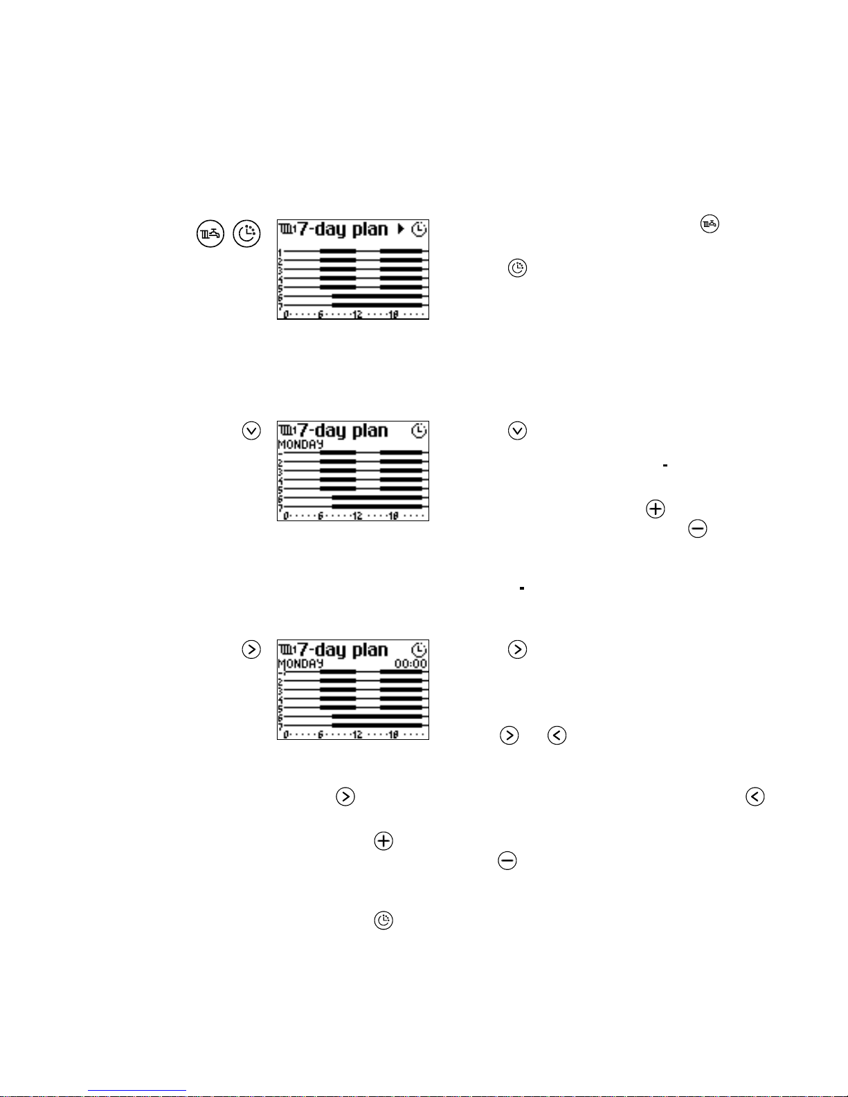
5.2 Setting the 7-Day Plan
The ECL 2000’s 7-day plan is active when the controller is in Automatic mode (see
page 15). The 7-day plan determines when comfort temperature will be maintained in
the system, and when night setback temperature will be maintained.
,
1. In the System Overview picture, press to
display the picture of the circuit.
2. Press
to display the current 7-day plan for the
selected circuit.
In the 7-day plan, the numbers 1-7 indicate the days from Monday to Sunday. A thin
time line indicates when night setback temperature should be maintained, and a thick
line indicates when comfort temperature should be maintained.
Now select a day or group of days for which the 24-hour program will be changed:
3. Press until the name of the first day appears
(Monday in this example). Note that the day’s
number is replaced by a cursor (
).
4. If you wish to select a group of days (for example
Monday through Friday), use
to add the cur-
rently selected day to the group. Use
to remove
the selected day from the group.
When a group of days is selected, the numbers of the days are highlighted while the
currently selected day is indicated by the
cursor.
Now set the 24-hour program for the selected day or group of days:
5. Press .
A cursor appears in the time line that represents the 24-
hour program for the selected day(s). The time of day
corresponding to the cursor position is displayed.
6. Use
and to move the cursor to the time of
day at which you wish to modify the plan.
If the plan includes changes from comfort to night setback temperature and vice
versa, the
push-button moves the cursor forward to the next change of mode.
always moves the cursor backwards in 15-minute steps.
7. Press
to select comfort temperature for the currently selected 15-
minute time interval. Press
to select night setback temperature.
Exit
To exit the 7-day plan:
1. Press
.
Page 24
Time Programming
EY.65.H4.02
18
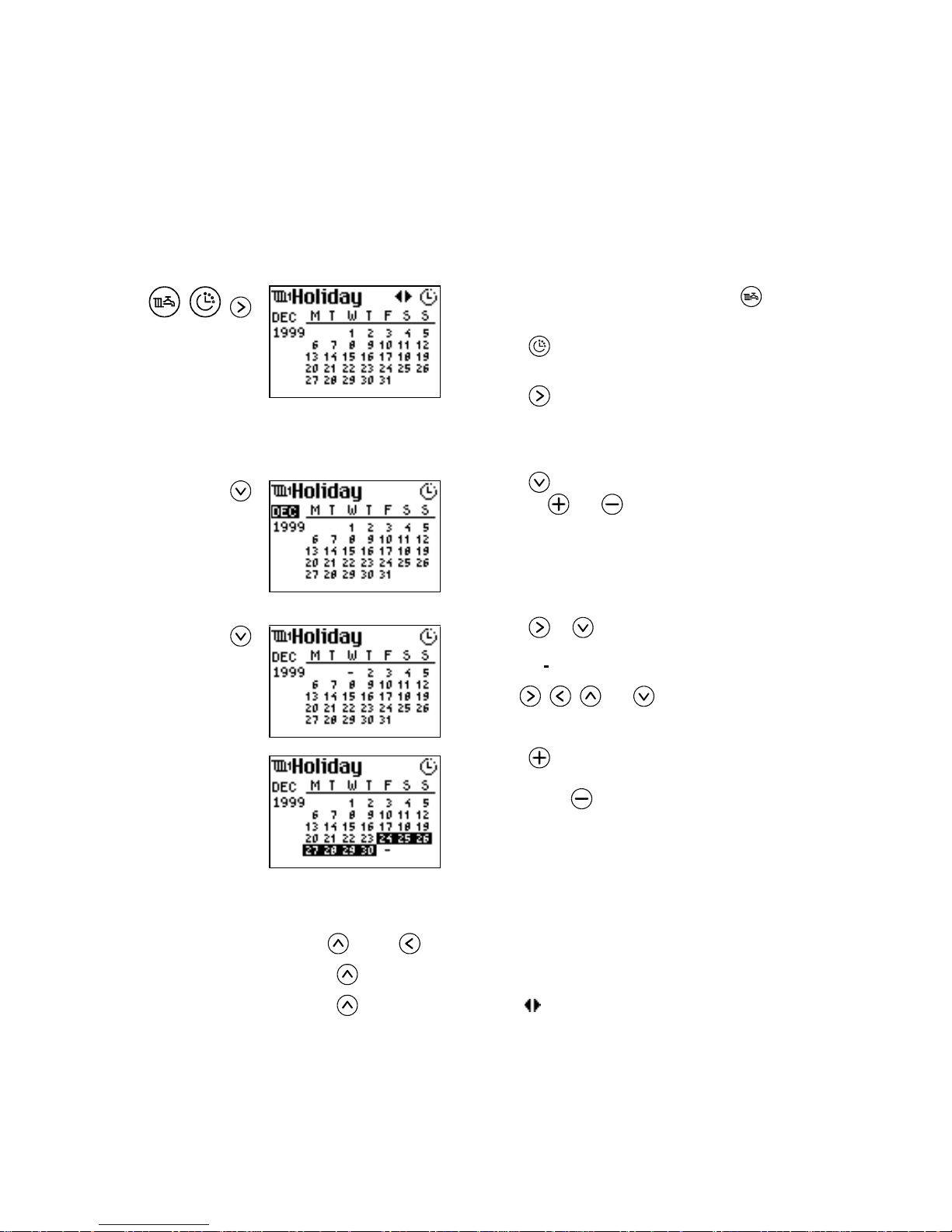
5.3 Setting the Holiday Plan
The ECL 2000’s Holiday Plan enables you to set up a special 24-hour program which
will be active for a limited number of days (the holiday period) which you select from
a calendar.
You set up the holiday plan for one circuit at a time:
, ,
1. In the System Overview picture, press until the
appropriate circuit picture appears.
2. Press
to display the 7-day plan. Details of this
picture are given on page 17.
3. Press
to display the Holiday picture.
The first thing to do is to set up the holiday period. First
select the month:
4. Press to highlight the name of the month, and
then use
and to change the holiday month.
The year changes automatically when the month
changes from Dec to Jan.
Now proceed to select the days of the holiday period:
5. Press or to move the cursor to the first day
of the selected month. The date is replaced by a
cursor (
).
6. Use
, , and to move the cursor to the
first day to be included in the holiday period.
7. Press to add the currently selected day to the
holiday period. The selected days are highlighted.
By pressing
, you remove the selected day from
the highlighted period.
The next step is to set up a 24-hour program for the holiday period. But first, you
must exit this part of the Holiday Plan facility:
8. Use
and/or to move the cursor back to the first date of the month.
9. Press
to move the cursor back to the name of the month.
10. Press
once more to display the symbol at the top right corner of the dis-
play.
See next page for further instructions.
Page 25
Time Programming
EY.65.H4.02
19
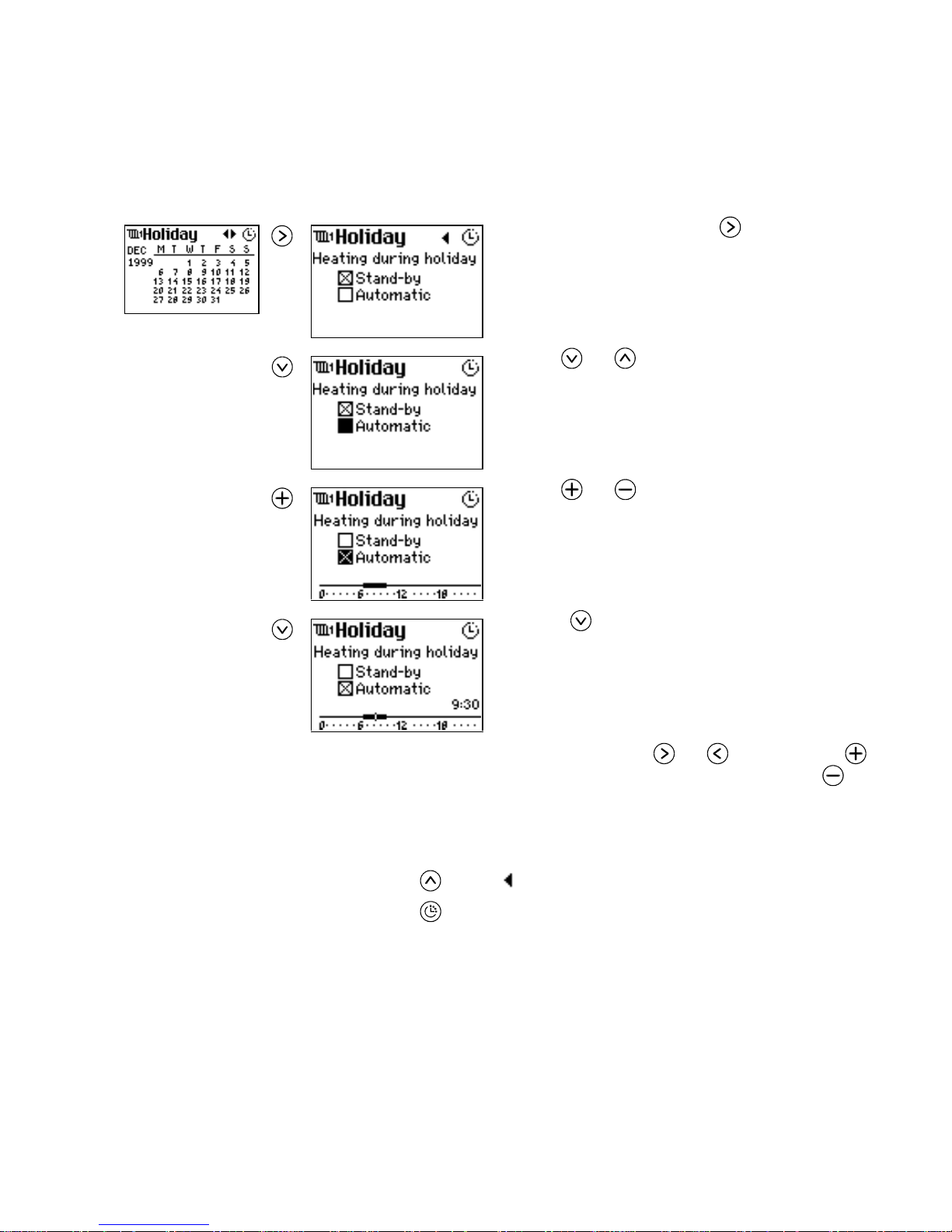
After setting up the holiday period, you are now ready to enter the 24-hour program
that the controller should follow during this period:
11. In the Holiday picture, press .
The ECL 2000 displays this picture, which allows you
to select an operating mode for the holiday. The X indicates the currently selected mode (Stand-by in the example).
12. Use
and
to move the cursor between Stand-
by and Automatic.
13. Use and to select or deselect an operating
mode (see page 3 for information about ECL
2000’s operating modes).
When you select Automatic, a time line appears at the
bottom of the display.
14. Press to move the cursor to the time line.
The time of day corresponding to the cursor position is
displayed.
Now you can set the 24-hour program for the holiday
period in the same way as you set a 24-hour program for
the normal 7-day plan:
and move the cursor,
selects comfort temperature (thick time line) and
selects night setback temperature (thin line). See page
17 for more detailed instructions.
Exit
To exit the holiday plan facility:
1. Press
until the symbol appears at the top right corner.
2. Press
.
Page 26
Entering the Access Code
EY.65.H4.02
20
6. ENTERING THE ACCESS CODE
The ECL 2000 always allows the user to display any parameter or setting. However,
the controller can be set up to prompt the user to enter an access code before he or she
is allowed to modify a setting. The controller has 2 levels of access codes:
• The service level code gives authorization to modify all settings of the ECL 2000.
This code is required to select a different application (see page 26), to configure
inputs and outputs (see page 27) and to modify the controller’s service settings
(see chapter 10, page 38).
• By entering the user level code, you are authorized to modify all settings that do
not require the service level code. These settings are the ones that may need
changing during normal day-to-day operation, for example a temperature setpoint
or the 7-day plan.
See page 72 for instructions on activating and modifying the access code.
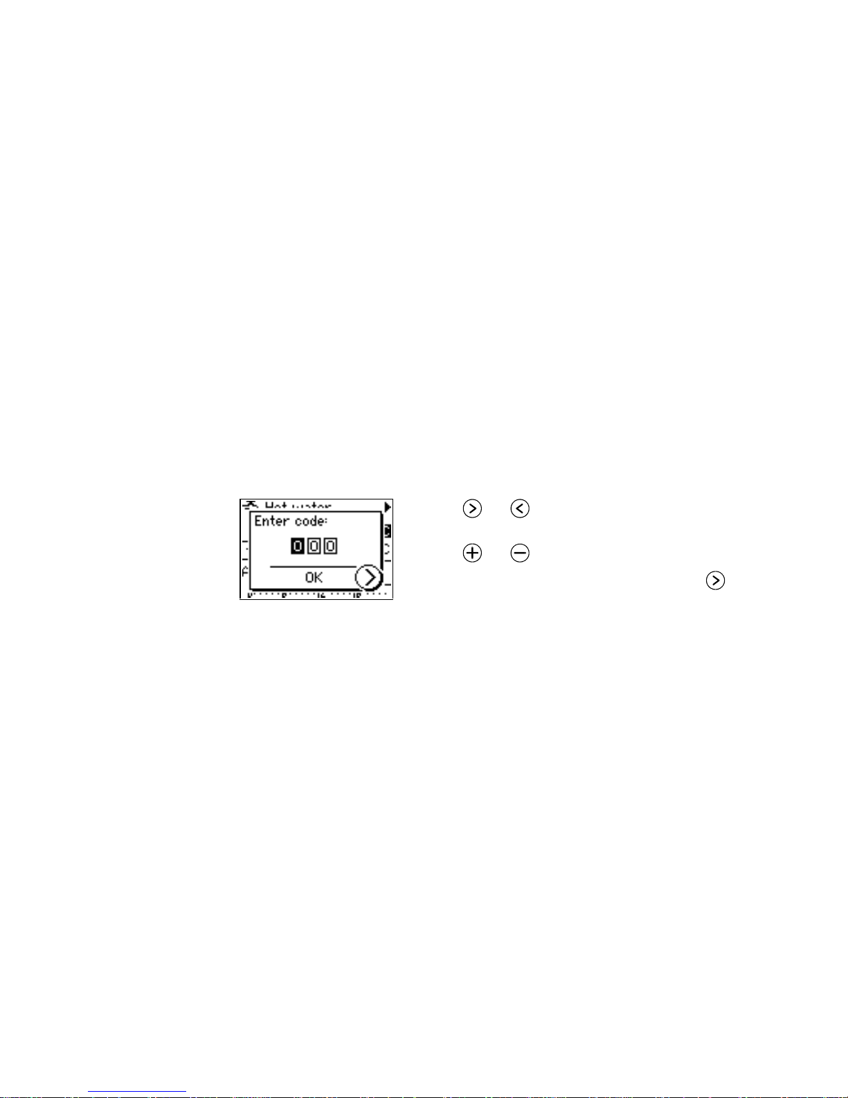
When you attempt to modify a setting, a pop-up similar to the one shown below appears:
1. Use and to move the cursor from one digit
to another.
2. Use
and to change the digits.
3. When you have entered the access code, press
.
The Access Code pop-up disappears. If you entered the
correct access code, you can now complete the operation you were about to perform.
When no front panel push-button has been operated for a 10 minute period, you must
enter the access code again before being allowed to modify any settings.
Page 27
Weather Compens at i on Curves
EY.65.H4.02
21
7. WEATHER COMPENSATION CURVES
Weather compensation means that the ECL 2000 regulates the heat circuit temperature in accordance with the outdoor temperature.
Weather compensation is controlled by two user-definable curves:
• A flow temperature curve
• A return temperature curve.
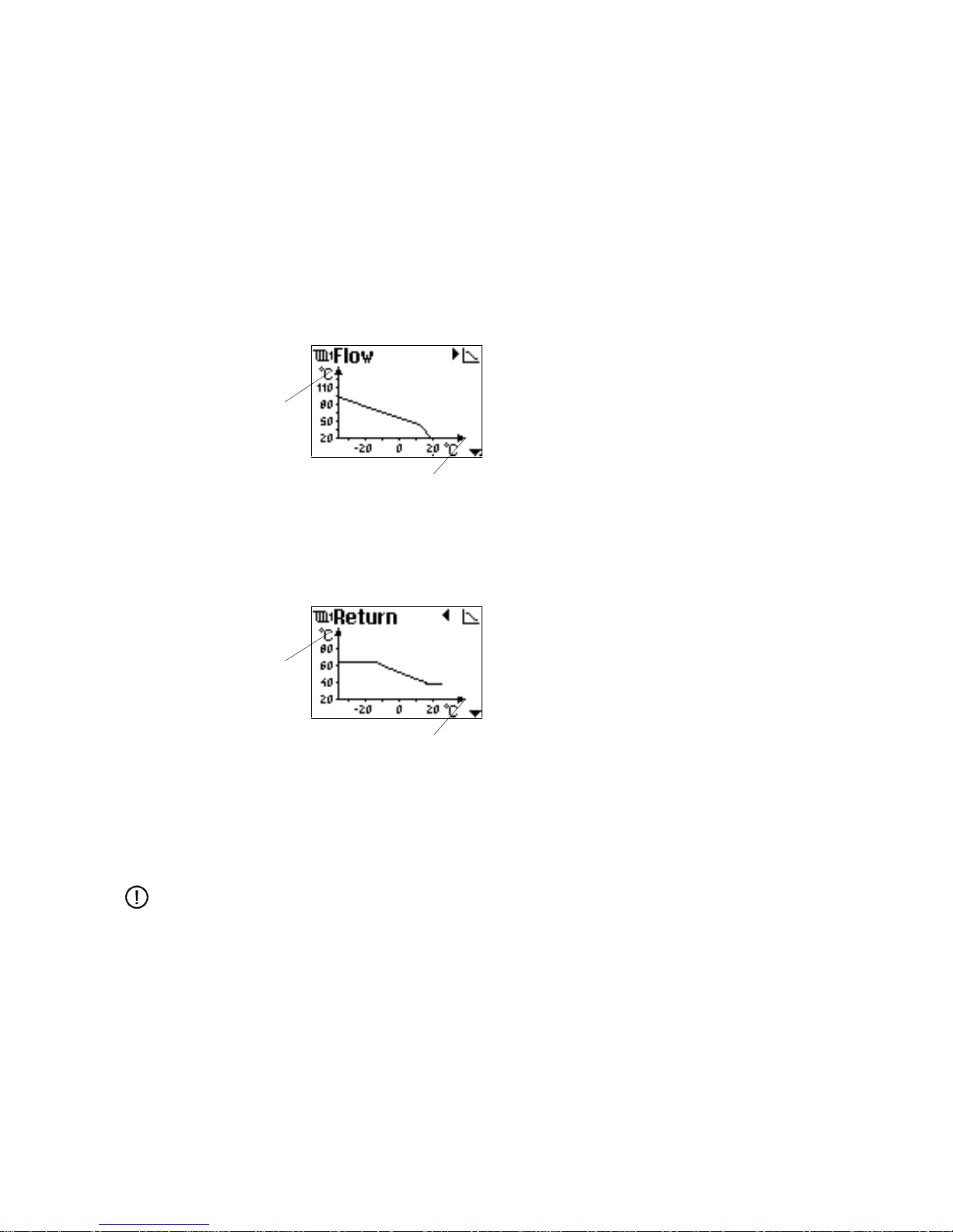
Flow temperature curve
Outdoor temperature
The flow temperature curve shows the reference flow
temperature in the heat circuit as a function of the outdoor temperature. By modifying this curve, you determine what the flow temperature should be for various
values of the outdoor temperature.
At low outdoor temperatures, you will normally want a
higher flow temperature, as shown in the curve to the
left.
You can set up maximum and minimum values for the
reference flow temperature. This is explained on
page 22.
Return temperature
curve
Outdoor temperature
The return temperature curve controls return temperature limiting in accordance with the outdoor temperature. The curve shows the acceptable return temperature
as a function of the outdoor temperature.
Normally, a low outdoor temperature means that a
higher return temperature will be allowed. This is also
the case with the curve shown to the left.
For further information on return temperature limiting,
see page 47 and 48 (heat circuit) and page 58 and 59
(hot-water circuit).
The following pages provide instructions for setting up the curves.
Note:
The setting of the flow and return temperature curve is essential for the functioning of
the ECL 2000. Therefore, it is important to check that the resulting curve is reasonable in relation to the controlled system.
Reference flow
temperature
Return temperature limit
Page 28
Weather Compens at i on Curves
EY.65.H4.02
22
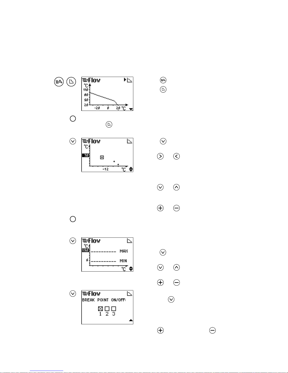
7.1 Adjusting the Flow Temperature Curve
The weather compensation curve for the flow temperature can be modified by setting:
A maximum and minimum value, 2 curve endpoints and, in addition to these, 3 break
points. Together, these parameters define the shape of the curve.
,
1. Press to select the desired heat circuit.
2. Press
to display the flow temperature curve.
!
Note:
If you press
while a hot-water circuit is selected, the ECL 2000 displays a pop-up
informing you that this facility is not available for hot-water circuits.
Moving curve
points
3. Press to display the currently defined curve
points.
4. Use
and to move the cursor to the point you
wish to modify.
The flow temperature (y co-ordinate) of the selected
point is highlighted to indicate that it can be modified.
5. Use
and to select either the flow temperature (y co-ordinate) or the outdoor temperature (x
co-ordinate) of the point.
6. Use
and to adjust the selected value.
!
Note:
If two curve points are placed in the same position, one point is automatically removed.
Setting maximum
and minimum values
7. Ensure that the outdoor temperature of a point is
selected (x co-ordinate value highlighted), and
press to display maximum and minimum val-
ues.
8. Use
and to select either the maximum or
minimum setting.
9. Use
and to adjust the selected setting.
Adding and removing curve
points
10. Ensure that the curve’s minimum value is selected,
and press
to display break points.
The checked box indicates the number of break points
that are currently active (in this example, 1 break point
is active – in addition to the two curve endpoints).
11. Use
to add a breakpoint or to remove one.
Page 29
Weather Compens at i on Curves
EY.65.H4.02
23
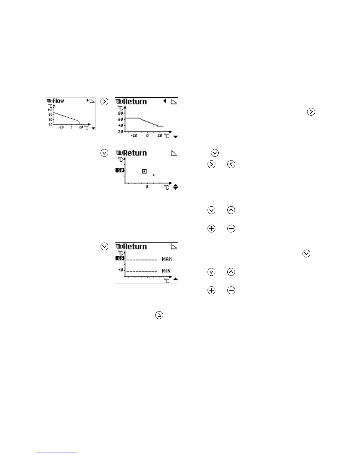
7.2 Adjusting the Return Temperature Curve
You modify the return temperature curve in the same way as when adjusting the flow
temperature curve (see page 22). However, for the return temperature curve, you can
only set two curve points. The curve can have no further break points.
To display the return temperature curve:
1. In the Flow Temperature Curve picture, press
.
Moving curve
points
2. Press to display the curve points.
3. Use
and to move the cursor to the point you
wish to modify.
The y co-ordinate value (the return temperature) of the
selected point is highlighted to indicate that it can be
modified.
4. Use
and to select either the y or x co-
ordinate (outdoor temperature) of the point.
5. Use
and to adjust the selected value.
Setting maximum
and minimum values
6. Ensure that the x co-ordinate of a point is selected
(x co-ordinate value highlighted), and press
to
display maximum and minimum values.
7. Use
and to select either the maximum or
minimum setting.
8. Use
and to adjust the selected setting.
Exit
To exit temperature curve editing:
1. Press
.
Page 30

Weather Compens at i on Curves
EY.65.H4.02
24
This page is intentionally left blank
Page 31

Configuring the ECL 2000
EY.65.H4.02
25
8. CONFIGURING THE ECL 2000
This section tells you how to begin using the ECL 2000 after it has been installed. The
ECL 2000 Installation Guide (ref. [2]) provides full details about the installation and
configuration of the ECL 2000.
8.1 Starting the ECL 2000 for the First Time
When the ECL 2000 is powered on, the controller displays the Danfoss logo.
The ECL 2000 is supplied with up to 17 different pre-programmed applications (see
below), accommodating a wide variety of plant configurations. Before the ECL 2000
is operational, you must select the application that matches your plant best. Once you
have selected an application, you have the possibility of customizing one or more
system parameters.
If the ECL 2000 has already been programmed with a pre-selected application, the
System Overview replaces the logo picture after a moment.
If no application is selected, the ECL 2000 automatically displays the Application 1
picture (see page 26), allowing you to select an application. See instructions on the
following pages.
8.2 ECL 2000 Types
Two different types of ECL 2000 are available. The table below summarizes the differences between the two types (see also page 89).
Type 1 Type 2
Inputs
Pt 1000 7 7
Pt 1000, 0-10 V, pulse
or digital
24
Outputs
Relay (pump control ) 3 3
3-point control (motor
valve control)
2 –
0-10 V (motor valve
control)
–3
Page 32

Configuring the ECL 2000
EY.65.H4.02
26
Power supply
230 V AC
24 V AC
24 V AC
Pre-programmed applications
1
1 – 14 1 – 17
8.3 Selecting an Application
This section explains how to select one of the ECL 2000’s pre-programmed applications. For an overview of available applications, see page 34.
To select an application:
1. Press the front panel
button.
If no application has been selected yet, the ECL 2000
displays the picture Application 1. However, if an application has already been selected, the picture of this
application is displayed. In this case, the picture’s title
is inverted, i.e. displayed in light characters on a dark
background.
2. Use and
to browse through available appli-
cations.
Each application picture shows a diagram of the system
configuration. Refer to the ECL 2000 Installation Guide
(ref. [2]) for system diagrams offering additional detail.
When you have found the application you need:
3. Keep the
button depressed for a few seconds.
While the
button is active, the picture’s title (in the
example “APPLICATION 10”) is inverted, one character at a time, until the whole title is displayed in light
characters on a dark background.
When all the characters of the title are inverted, this
indicates that the controller is configured to use this
application.
The
symbol appears briefly, indicating that you can
access further configuration pictures. After a moment,
the controller automatically displays the first configuration picture (see next page).
1
See page 34 for an overview of ECL 2000 applications
Page 33

Configuring the ECL 2000
EY.65.H4.02
27
8.4 Configuring I nputs and Outputs
8.4.1 Operating Configuration Pictures
Depending on the type of ECL 2000 you are working with and the application you
have selected, it may be possible to customize one or more sensor inputs (S8, S9, S10
and S11) and one relay output (P3). Furthermore, if the ECL 2000 LON option is installed, you can configure four LON inputs (L1, L2, L3 and L4). This section explains
how to operate the function. The following sections give some details about possible
settings. Further information is available in the ECL 2000 Installation Guide (ref.
[2]).
When you have selected an application, you are ready to configure inputs and outputs:
1. In the Application picture (see facing page), press
to access Input
settings.
Configuring Sensor
Inputs
The first pictures in the series allow you to configure the ECL 2000’s sensor inputs.
2. Use to select the different parameters.
The arrow symbol at the top right corner of the display disappears, indicating that you
can now select and set the individual parameters of the picture.
3. Use
to modify the parameters Sensor, Circuit and Type.
4. Use
and to modify the remaining parameters.
Section 8.4.2 starting on page 30 provides an overview of the possible settings of sensor input parameters.
Note:
The sensor inputs S10 and S11 and the corresponding configuration pictures are only
available for the ECL 2000 Type 2.
Page 34

Configuring the ECL 2000
EY.65.H4.02
28
To exit a configuration picture:
5. Press
until the arrow symbol at the top right corner reappears.
6. Use
or to access other configuration pictures.
See also page 29.
Configuring LON
Inputs
A maximum of 4 sensors can be configured as input from the LON network. To access LON configuration pictures:
1. Press
in the last sensor input picture (Input S9 for the ECL 2000 Type
1 and Input S11 for the Type 2).
X
2. Use
to select the different parameters.
3. Use
to modify the parameters Sensor, Circuit and Unit.
4. Use
and to modify the parameter Poll.
Section 8.4.3 starting on page 32 gives some details about the possible settings of the
LON inputs. See also section 10.4.6 on page 70 for information on the LON address.
Configuring the Relay
Output
Some ECL 2000 applications allow you to change the function of the relay output P3.
When this is possible, you can access the Output P3 picture by pressing
in either
the last sensor picture (Input S9 or Input S11) or, if the LON option is installed, in the
Input L4 picture. This is illustrated below. Section 8.4.3 starting on page 32 gives
details about the possible settings of P3.
1. Use to select the parameter Function.
2. Use
to modify the setting.
Page 35

Configuring the ECL 2000
EY.65.H4.02
29
Save and Exit
To exit the configuration facility and save the selected settings:
1. Press
until the arrow symbol appears at the top right corner of the dis-
play.
2. Press
again.
If you have selected a different application, or if one of the parameters Sensor, Cir-
cuit or Type has been changed, the ECL 2000 is reset, which takes a few moments.
Meanwhile, the Danfoss logo is shown in the display.
Page 36

Configuring the ECL 2000
EY.65.H4.02
30
8.4.2 Sensor Inputs
This section explains the setup of the ECL 2000’s sensor inputs. See the ECL 2000
Installation Guide (ref. [2]) for further information.
Note:
It is not possible to set up two sensors with the same function (Sensor) in one circuit
(Circuit). For example, you cannot have two room temperature sensors both affecting
circuit 1. The ECL 2000 automatically excludes this and similar illegal settings.
Furthermore, not all combinations of settings (e.g. Sensor and Type) are allowed. The
ECL 2000 keeps track of this and only allows you to select valid settings.
Sensor This setting tells the ECL 2000 what is measured by means of the sensor connected to
this input. The setting can have the following values:
Value Description
Room temp.
Room temperature
Sun intens.
Sun intensity
Wind veloc.
Wind velocity
Flow
Water flow
Energy
Energy measurement
Clock func.
An external timer is connected to the input. Overrides the normal program set up for the circuit. When the timer input is OFF (0), the circuit
is in Automatic mode. When the timer input is ON (1), the circuit is in
Comfort mode
Other
Universal limiter
None
No function
Circuit This parameter determines which circuit is affected by the sensor.
Value Description
None
No circuits affected
Circuit 1
Heat circuit 1
Circuit 2
Heat circuit 2
Hot water
Hot-water circuit
Circuit 1+2
Circuits 1 and 2
All circuits
All heat and hot-water circuits in the system
Page 37

Configuring the ECL 2000
EY.65.H4.02
31
Type This setting indicates what type of sensor is connected. The following sensor types
are supported:
Value Description
Pt 1000
Temperature dependent resistance: 1000
at 0 °C
ESMF
Remote control device with a built-in Pt 1000 room temperature sensor
Pulse
Pulse count
0–10 V
The sensor delivers a voltage in the range 0-10 V
Digital
Digital input
Amplific., Offset Amplification, Offset.
For a 0–10 V sensor, the ECL 2000 must convert the input voltage received from the
sensor into the correct value, using the correct unit of measurement. The parameters
Amplific. (amplification) and Offset are used to perform this calculation. Their func-
tion is illustrated in Figure 2.
Offset
Value [m/s, l/h, ...]
Value = Amplification * Input + Offset
Input signal [V]
Figure 2. Amplification and Offset
Scaling, Interval These parameters are used to convert the number of pulses received from a pulse in-
put into the correct value and unit of measurement. See the ECL 2000 Installation
Guide (ref. [2]) for details on these parameters.
Page 38

Configuring the ECL 2000
EY.65.H4.02
32
8.4.3 LON Inputs
The parameters of the LON input configuration pictures can assume the values described in the following.
Sensor This setting tells the ECL 2000 what is being measured by means of the LON sensor.
Value Description
Outd. temp.
Outdoor temperature
Note:
When Outd. temp. is selected, the ECL 2000 uses the LON sensor to
measure outdoor temperature. Any outdoor temperature sensor connected
directly to the ECL 2000 (typically via sensor input S3) is disabled
Flow
Water flow
Wind veloc.
Wind velocity
Energy Energy measurement. When Energy is selected, values for the accumu-
lated energy are automatically collected from the same device
None
The LON input is not used, i.e. no input is taken from the LON network
Circuit This parameter determines which circuit is influenced by the collected data.
Value Description
None
No circuits affected
Circuit 1
Heat circuit 1
Circuit 2
Heat circuit 2
Hot water
Hot-water circuit
Circuit 1+2
Circuits 1 and 2
All circuits
All heat and hot-water circuits in the system
Poll This parameter determines how often the ECL 2000 will poll the LON sensor.
Value Description
X s The number of seconds between sensor polls. For example, if Poll is set
to 25 s, the ECL 2000 reads the actual value from the sensor every 25
seconds
Poll can be set to values in the range 5 – 60 s for all sensor types. After
an external device has been polled 3 times without having anwered, this is
considered a sensor fault
Page 39

Configuring the ECL 2000
EY.65.H4.02
33
Unit The Unit parameter is available when Sensor is set to Flow or to Energy. When Sen-
sor is set to Flow, the Unit parameter can be set as follows:
Value Description
l/h
Water flow is being measured in liter per hour
m3/h
Water flow is being measured in m
3
per hour
Note:
When the flow unit is set to l/h, there is a risk of an overflow error if the measured
water flow exceeds 1024 l/h. This will lead to a blank flow reading on the
ECL 2000’s display. See the Technical Manual for the ECL 2000 LON Option (ref.
[4]).
When Sensor is set to Energy, the Unit parameter can be set as follows:
Value Description
kW
Energy is being measured in kW. When this setting is active, the accumulated energy is measured in MWh
MW
Energy is being measured in MW. When this setting is active, the accumulated energy is measured in GWh
Note:
When the energy unit is set to kW, there is a risk of an overflow error if the measured
energy (power consumption) exceeds 1024 kW. This will lead to a blank energy
reading on the ECL 2000’s display. See the Technical Manual for the ECL 2000 LON
Option (ref. [4]).
8.4.4 Relay Output
For some applications, you can also customize the ECL 2000’s relay output P3.
Function The relay output parameter Function can be set to the following values:
Value Description
Pump 3
The output controls a pump. This is the default setup for some applications
Timer
When this value is selected, one of the controller’s circuits is dedicated to
a timer function. The output is set to ON and OFF in accordance with the
7-day plan for the timer circuit. See also page 10.
Alarm
The relay output is used as an alarm indication, i.e. the output is set to
ON and OFF in accordance with the ECL 2000’s Alarm Setup (see page
66).
Page 40

Configuring the ECL 2000
EY.65.H4.02
34
8.5 Overview of ECL 2000 Applications
Heat circuit and hot-water circuit with indirect control
via heat exchanger.
Heat circuit and hot-water circuit with direct control of
storage tank.
Common primary heat exchanger for a heat circuit and a
hot-water circuit with indirect control of storage tank.
Common primary heat exchanger for a heat circuit with
a mixing valve and a hot-water circuit with indirect
control of storage tank.
Heat circuit and hot-water circuit with indirect control
of storage tank.
Common primary heat exchanger for a heat circuit and a
hot-water circuit with indirect tank charging system.
Common primary heat exchanger for a heat circuit with
mixing valve and a hot-water circuit with indirect tank
charging system.
Common primary heat exchanger for a heat circuit and a
hot-water circuit with mixing valve and indirect tank
charging system.
Page 41

Configuring the ECL 2000
EY.65.H4.02
35
Two separate heat circuits.
Two separate heat circuits and a hot-water circuit with
direct control of storage tank.
One separate heat circuit. In addition to this, a common
primary heat exchanger supplying one heat circuit and
one hot-water circuit with indirect control.
Two heat circuits with common heat exchanger. One
heat circuit has a mixing valve.
Two interdependent heat circuits and a hot-water circuit
with direct control of storage tank.
Common primary heat exchanger for one heat circuit
with mixing valve, one heat circuit without and a hotwater circuit with indirect control of storage tank.
Two heat circuits with common heat exchanger, where
one circuit has a mixing valve. Hot-water circuit with
indirect control via heat exchanger.
Note: This application requires ECL 2000 type 2.
Two separate heat circuits. Hot-water circuit with indirect control via heat exchanger.
Note: This application requires ECL 2000 type 2.
Two separate heat circuits. Hot-water circuit with indirect control of storage tank.
Note: This application requires ECL 2000 type 2.
Page 42

Manual Override
EY.65.H4.02
36
9. MANUAL OVERRIDE
When the ECL 2000’s Manual Override function is active, you can control system
components, circulation pumps and valve motors from the ECL 2000’s front panel.
,
1. Press to select the circuit that you wish to con-
trol manually.
2. Press
to activate manual control.
The LED above the
button lights up and all four
LED’s indicating the controller’s operating mode are
switched off. The controller displays a picture showing
the pumps and valves of the selected circuit, as well as
status information.
!
Note:
While the Manual Override function is active, automatic control of all circuits in the
plant is disabled. Automatic control is disabled, as long as the LED above the
is
lit.
While Manual Override is active, frost-protection of the plant is disabled.
3. Press
and to select the pump or valve you wish to operate (see
facing page).
The text below the selected component is highlighted to indicate the selection.
4. Press
and to operate the device. These buttons work as indicated in
the table below.
Push-button Pump Motor valve
Pump is set toONMotor valve OPENs while button is pressed. After the but-
ton has been kept depressed for about 5 seconds, the valve
will move continuously towards the open position until the
button is pressed again
Pump is set to
OFF
Motor valve CLOSEs while button is pressed. After the
button has been kept depressed for about 5 seconds, the
valve will move continuously towards the closed position
until the button is pressed again
Note:
If a motor valve is moving when
is pressed, it will continue running. You can stop
the valve by pressing
or
.
It is not possible to control a timer circuit manually.
Page 43

Manual Override
EY.65.H4.02
37
To display today’s and yesterday’s logs for the selected circuit:
1. In the Manual picture, press
to display today’s log and once more to
see yesterday’s log.
The circuit’s last component is selected. The
symbol indicates that you
can proceed to the next
picture (today’s log) by
pressing
.
Today’s log. The fully
drawn curve indicates the
flow temperature, the
dotted curve shows the
return temperature.
1
Yesterday’s log.
The ECL 2000 keeps logs of the temperature measured by all connected sensors. You
can display these logs from the Common Functions service menu. See page 67.
Exit
To exit Manual Override and revert to automatic control of the plant:
3. Press
again.
1
See Appendix C, page 87 for a complete list of the data displayed in Log pictures
Page 44

Service Settings
EY.65.H4.02
38
10. SERVICE SETTINGS
The ECL 2000’s service menus provide facilities for displaying and modifying:
• Heat circuit settings
• Hot-water circuit settings
• Settings concerning the overall operation of the ECL 2000, for example the cur-
rent date and time. These are called Common Functions.
The options that are available in service menus depend on the application that is selected and the setup of the system. This chapter describes all service menu options
that can be available in a ECL 2000. Please disregard any explanations of parameters
not available in your particular system.
Select menu item/
setting
Next/previous picture
See also the service menu overview in Appendix B. The overview shows all available
service pictures and options.
Page 45

Service Settings
EY.65.H4.02
39
10.1 Operating Service Menus
Accessing service menus The diagram on the facing page illustrates how the ECL 2000’s service menus are
operated. To access service menus for a heat circuit or a hot-water circuit:
1. Press
to select the desired circuit.
2. Press
to activate the service menu.
The controller displays the service menu for the circuit you selected. In the diagram
on the facing page, heat circuit 1 was selected prior to pressing
.
To access the Common functions service menu directly (see page 62):
1. In the System Overview picture, press
.
Operating service menus In all service menus,
and are used to select menu items. Selected menu items
are highlighted. If, for example, you wish to view and modify pump and motor valve
settings:
1. Press to select Pump/valve.
Each menu item has a number of setting pictures associated with it. How many, depends on the selected application (see page 26) and the type of controller you are
working with. You use
and to access these pictures:
2. Press
to access the first Pump/valve setting picture.
The ECL 2000 now displays the first set of parameters for pumps and valves in circuit
no. 1. The symbol in the upper right-hand corner of the display indicates the number
of pictures available and which one of these is currently displayed. In the diagram, the
symbol indicates that there are a total of 3 setting pictures, that the first one of these is
currently displayed and that you can access the next setting picture by pressing
.
To select a parameter, you use
and . The selected setting is highlighted. To
change the value of the selected parameter:
3. Press
or .
For the currently selected parameter, the line at the bottom of the picture indicates:
Current setting
Previous setting
Maximum limit
Minimum limit
Factory settin g
Figure 3. The line at the bottom of a service setting picture
Page 46

Service Settings
EY.65.H4.02
40
To exit a service setting picture:
4. Press
once to return to the service menu, and once more to exit the service
menu.
All changes you have made are saved automatically.
Page 47

Service Settings
EY.65.H4.02
41
10.2 Heat Circuit Functions
This section describes the parameters that can be set up for a heat circuit via the
service menus.
This picture is the service menu for a heat circuit. Heat
circuit functions are divided into 4 groups corresponding to the menu items: Building, Pump/valve, PI con-
stants and Limiter. See the overview diagram on page
38.
Each menu item gives access to a number of setting pictures allowing you to view and
modify various parameters for the heat circuit. The number of pictures and parameters
available depends on the type of controller you are working with and the application
you have selected (see page 26 for information about ECL 2000 applications).
This section describes all parameters that can be set for a heat circuit. Please disregard
the descriptions of any parameters not available in your specific system setup.
Instructions for operating the ECL 2000’s service menus are provided on page 39.
10.2.1 Building Settings
This section describes the parameters you can set in pictures under the Building menu
item.
Summer cut-off The summer cut-off function makes the controller close down the heat circuit.
Display text Parameter Default value,
range
Description
Outdoor temp.
Outdoor temperature
Default value:
18 °C
Range:
10-30 °C
When the outdoor temperature reaches
this value, summer cut-off is activated,
and the heat circuit it closed down
Room temp.
Room temperature
Default value:
24 °C
Range:
10-30 °C
When the room temperature reaches this
level, summer cut-off is activated
Note:
By default, the circulation pump of the heat circuit is switched off when the calcu-
lated flow temperature drops below 20 °C. See page 45.
Page 48

Service Settings
EY.65.H4.02
42
The diagram in Figure 4 illustrates the summer cut-off function. When the measured
outdoor or room temperature exceeds the setpoint (Outdoor temp. or Room temp.
setting) by 0.5 K, the flow temperature is reduced. The night setback level is main-
tained until the filtered outdoor/room temperature drops below the setpoint – 0.5 K.
See page 71 for information on setting parameters for calculating the filtered temperature.
[Hours]
Plant switched off
Filtered temperature
Temperature
Measured temperature
Time
} 1K
°C
20
18
16
Figure 4. The summer cut-off function
Optimizer
The purpose of the ECL 2000’s Optimizer function is to help run the plant in the most
economic manner possible. The Optimizer offers functions for:
• Calculating the optimum starting time in order for room temperature to reach the
desired level (the comfort temperature) at the time defined in the 7-day plan.
• Calculating how much ahead of time the system can be switched to night setback
temperature, making sure, however, that the room temperature does not drop by
more than 1 K before the pre-programmed night-setback time.
• Selecting the optimum method for pre-heating the system.
Settings for the optimizer are described on the following pages.
By default, the Optimizer functions are disabled. This has been accomplished by setting the parameters Pre-heat period: Max. limit and Cooling period: Max. limit to
0 hours. The Optimizer functions can be enabled by changing these settings as indicated on page 43. Optimizer heating and cooling can be enabled/disabled separately.
Page 49

Service Settings
EY.65.H4.02
43
Pre-heat period This is the function that allows the controller to calculate the optimum starting time. If
the system is equipped with a room temperature sensor, this function is adaptive.
If no room temperature sensor is connected, the controller estimates the room temperature as a function of the actual outdoor temperature and the default pre-heat period entered by the operator (see below). Furthermore, if the system has been on night
setback for a long period, the controller increases the length of the pre-heat period. In
this way, the controller is able to compensate for fluctuations in outdoor temperature
and accumulated heat in buildings.
Display text Parameter Default value,
range
Description
Default
Default preheat period
Default value:
23 hours
Range:
0-24 hours
As default, you must enter a pre-heat
period that you estimate is suitable given
the following conditions:
• Outdoor temperature 0 °C
• Actual room temperature 5 °C
• Comfort temperature setting 20 °C
• Flow temperature 80 °C during the
heating perio d
Max. limit
Maxi mum preheat period
Default value:
0 hours
Range:
0-24 hours
The maximum pre-heat period the system
is allowed to calculate and use. Change
this setting to enable the optimizer function
Calculated
Calculated
pre-heat period
Range:
0-24 hours
The pre-heat period calculated by the
controller using the actual outdoor temperature. This parameter is read-only and
cannot be set
Cooling period These settings enable the controller to calculate the cooling period, i.e. how soon the
plant can be switched to night setback temperature while still ensuring that the room
temperature only drops by 1 K before the pre-programmed night setback time.
Display text Parameter Default value,
range
Description
Default
Default cooling period
Default value:
1 hour
Range:
0-24 hours
You must enter a default cooling period
corresponding to the following conditions:
• Outdoor temperature 0 °C
• Actual room temperature 20 °C
• Room temperature reduction = 1 K
Max. limit
Maximum
cooling period
Default value:
0 hours
Range:
0-24 hours
The maximum cooling period the system
is allowed to calculate and use. Change
this setting to enable the optimizer function
Calculated
Calculated
cooling period
Range:
0-24 hours
The cooling period calculated by the
controller using the actual outdoor temperature. This parameter is read-only and
cannot be set
Page 50

Service Settings
EY.65.H4.02
44
Pre-heat method This function enables the controller to determine the flow temperature level during
the pre-heat period. It is possible to:
• Use the boost function, which increases the flow temperature by a user-defined
percentage. The purpose is to reach comfort room temperature sooner, that is, reduce the duration of the pre-heat period.
• Use the slope function, which increases the flow temperature gradually. The aim
is to avoid an unnecessary sudden load of the district heating network and also to
prevent the return temperature from getting too high.
Note:
When Slope time is set, the gradual increase of the flow temperature level is applied
even if the Optimizer function is disabled.
Display text Parameter Default value,
range
Description
Boost factor
Default value:
0 %
Range:
0-100 %
The percentage by which the flow temperature should be increased during the
pre-heat period
Slope time
Default value:
0 min.
Range:
0-200 min.
The length of the time interval during
which the flow temperature should be
increased gradually to its comfort level
Night setback disable This function disables night setback when the outdoor temperature drops below a
user-defined limit.
Display text Parameter Default value,
range
Description
Disable at
Default value:
–15 °C
Range:
OFF,
–29 - 15 °C
When Disable at is set to a temperature,
night setback is disabled when the actual
outdoor temperature is below this limit.
When the outdoor temperature lies in the
interval between 15 °C and the Disable
at temperature setti ng, night setback is
gradually reduced
When Disable at is set to OFF, night
setback is never disabled
Page 51

Service Settings
EY.65.H4.02
45
10.2.2 Pump/Valve Settings
This section describes the parameters you can set in pictures under the Pump/valve
menu item.
Pump The following parameters can be set for pump operation:
Display text Parameter Default value,
range
Description
Overrun
Pump overrun
period
Default value:
3 min.
Range:
0-30 min.
The number of minutes the pump will
continue to run after the calculated flow
temperature setpoint has dropped below
20 °C. After this, the pump will be
stopped
Exercise
Pump exercise Default value:
ON
Range:
ON, OFF
When the pump has been stopped for 72
hours, pump exercise will take place,
provided that this parameter is ON. This
means that at 12:00 (noon), the pump
will be started and run for 1 minute
Night stop
Default value:
OFF
Range:
ON, OFF
During the night setback period, it is
generally desirable to stop the pump, or
at least reduce the number of revolutions.
When a normal pump is used, the parameter is set to OFF. In this case, the
controller stops the pump when the calculated flow temperature drops below
20 °C.
The ON setting is used for pumps with
control of the differential pressure across
the pump. This type of pump has a separate input that can be used to instruct the
pump to reduce its number of revolutions.
When the Night stop parameter is set to
ON, the ECL 2000 sends a STOP signal
to the pump as soon as a night setback
period starts, thus causing the pump to
reduce its number of revolutions, regardless of other pump control criteria.
For further information about the connection and use of this type of pump, see
the ECL 2000 Technical Manual
(ref. [3])
Motor valve The following parameters can be set for the motor valve in the heat circuit:
Display text Parameter Default value,
range
Description
Stroke
Default value:
16 mm
Range:
1-50 mm
Stroke of the valve motor
Page 52

Service Settings
EY.65.H4.02
46
Display text Parameter Default value,
range
Description
Run time
1 mm
Running time
1 mm
Default value:
8 seconds
Range:
1-99 seconds
The time required for the spindle of the
motor valve to move 1 mm
Exercise
Valve exercise Default value:
OFF
Range:
ON, OFF
When the valve motor has not been running for 72 hours, valve exercise will
take place, provided that this parameter
is ON. This means that at 12:00 (noon),
the gear motor will be started and the
valve will be activated for 3 minutes in
the opening direction and 3 minutes in
the closing direction
Flow cut-off Depending on the type of ECL 2000 and the type of application you have selected, it
is possible to customize 1 or more sensor inputs (see page 27). If one of these inputs is
used to measure the water flow, the controller can be set up to close the valve if the
flow in the system falls below a user-defined limit.
The following settings are related to flow cut-off caused by measured flow data:
Display text Parameter Default value,
range
Description
Cut-off time
Default value:
0 min.
Range:
0-30 min.
The period during which the valve is
closed
Min. flow
Minimum flow Default value:
0.0 l/h
Range:
0.0-999 l/h or
0.0-999 m
3
/h
If the water flow in the system is below
this limit, the valve is closed
The range and unit depend on the selected application and flow sensor
Alternatively, if one of the user-definable inputs is set up as a digital input, this signal
can be used to activate flow cut-off. In this case, the valve is closed when the input is
short-circuited. For such a configuration, only the cut-off time can be set.
In more detail, the flow cut-off function works as follows:
1. The ECL 2000 detects that the condition for activating flow cut-off is present.
2. The ECL 2000 waits for 5 minutes before closing the valve.
3. The valve remains closed for the period of time specified in Cut-off time.
4. The valve is reopened and the ECL 2000 checks whether the flow cut-off condi-
tion is still present.
5. If this is the case, the valve is closed after a delay of 5 minutes. If the flow cut-off
condition is no longer present, the valve remains open.
Page 53

Service Settings
EY.65.H4.02
47
10.2.3 PI Constant Settings
This section describes the parameters you can set in pictures under the PI Constant
menu item.
Flow temp. control This group of settings determine how the flow temperature is controlled. The follow-
ing parameters can be set:
Display text Parameter Default value,
range
Description
Neutr. zone
Neutral zone Default value:
3 K
Range:
0-9 K
When the flow temperature lies within
the neutral zone, the valve motor is not
activated
P-band
Proportional
band
Default value:
70 K
Range:
1-99 K
Indicates the amplification in the control
loop. If the flow temperature deviates
from the reference temperature, the motor will be positioned proportionally to
the temperature deviation and the proportional band setting
Integr. time
Integration
time
Default value:
20 seconds
Range:
0-999 seconds
In case of a constant control error signal,
the motor will have moved by an amount
equal to that caused by the P-band after
the integration time has elapsed
When the integration time is set to 0, the
integral action is disabled
Return temp. limiter
The controller can be set up to adjust the flow temperature if the actual return temperature either:
• Rises above the return temperature setpoint (maximum limiting)
or
• Falls below the return temperature setpoint (minimum limiting).
The return temperature setpoint is calculated from the return temperature curve (see
page 23).
The following parameters can be set for this control function (see also page 48):
Display text Parameter Default value,
range
Description
Amplification
Default value:
– 0.3 K
Range:
– 25.0 - 25.0
K
Amplification for return limiter
Integr. time
Integration
time
Default value:
30 min.
Range:
0-200 min.
Integration time
Page 54

Service Settings
EY.65.H4.02
48
Room influence These settings determine how the room temperature should influence flow tempera-
ture control. They are only applicable when a room sensor is connected in the heat
circuit.
Display text Parameter Default value,
range
Description
Max. amplific.
Maximum
amplification
Default value:
0.0 K
Range:
– 25.0 - 25.0
K
If the room temperature exceeds the
room temperature setpoint, the flow temperature in the heat circuit will be reduced according to the Max. amplific.
setting
Min. amplific.
Minimum amplification
Default value:
0.0 K
Range:
– 25.0 - 25.0
K
If the room temperature falls below the
room temperature setpoint, the flow temperature in the heat circuit will be increased according to the Min. amplific.
setting
Adaptive
Default value:
OFF
Range:
ON, OFF
When the setting is ON, the flow temperature is adjusted according to variations of the room temperature over a
period of time
!
Note:
When this setting is ON, the Max. am-
plific. and Min. amplific. settings should
be symmetrical with respect to 0, for
example, Max. amplific. = –3 K and
Min. amplific. = + 3 K
10.2.4 Limiter
This section describes the parameters you can set in pictures under the Limiter menu
item.
Return temperature The following settings affect the return temperature limiter. See also page 47.
Display text Parameter Default value,
range
Description
Type
Type of limitation
Default value:
MAX
Range:
MIN, MAX
Type of return temperature limitation
used: maximum or minimum. The flow
temperature is modified, when the return
temperature is either above the calculated setpoint or below it
Calc. setpoint
Calculated
setpoint
– The setpoint for the return temperature,
calculated from the return temperature
curve. This parameter is read-only and
cannot be set
Page 55

Service Settings
EY.65.H4.02
49
Flow This and the following functions (Energy, Wind, Sun and Universal) are related to
the sensors you connect to those inputs that can be customized after you have selected
an application for the controller (see page 27).
The Flow function requires that the flow in the heat circuit is being measured. It enables the controller to change the flow temperature if the current flow in the circuit
exceeds the flow setpoint.
Display text Parameter Default value,
range
Description
Setpoint
Default value:
1.00 m
3
/h
Range:
0.0-999 l/h or
0.0-999 m
3
/h
Flow setpoint. Measured flow above this
value causes a change in the calculated
flow temperature
The range and unit depend on the selected application and flow sensor
Amplification
Default value:
–0.3 K
Range:
–25.0 - 25.0 K
Amplification factor for modification of
calculated flow temperature
A negative amplification causes a reduction of the calculated flow temperature, a
positive amplification causes an increase
Integr. time
Integration
time
Default value:
15 min.
Range:
0-200 min.
Integration time for flow influence
Energy This limiter function is available when energy consumption is being measured.
Display text Parameter Default value,
range
Description
Setpoint
Default value:
100 kW
Range:
0.0-999 kW or
0.0-999 MW
When the energy consumption exceeds
the setpoint, the calculated flow temperature in the heat circuit is modified
The range and unit depend on the selected application and energy measuring
device
Amplification
Default value:
–1.0 K
Range:
–25.0 - 25.0 K
Amplification factor for modification of
calculated flow temperature caused by
energy consumption
A negative amplification causes a reduction of the calculated flow temperature, a
positive amplification causes an increase
Integr. time
Integration
time
Default value:
30 min.
Range:
0-200 min.
Integration time for energy consumption
influence
Page 56

Service Settings
EY.65.H4.02
50
Wind This function requires that a wind velocity sensor is connected to the system. It in-
creases the flow temperature in the heat circuit if the wind velocity grows above the
setpoint.
Display text Parameter Default value,
range
Description
Setpoint
Default value:
10 m/s
Range:
0-50 m/s
When the wind velocity is above this
value, the calculated flow temperature
will be modified according to the amplification factor
Amplification
Default value:
0.1 K
Range:
–25.0 - 25.0 K
Amplification factor for modification of
calculated flow temperature caused by
wind velocity
A negative amplification causes a reduction of the calculated flow temperature, a
positive amplification causes an increase.
Normally, the amplification is positive
Sun This function requires that a sun sensor is connected to the system. It reduces the flow
temperature in the heat circuit when the sun intensity rises above the setpoint.
Display text Parameter Default value,
range
Description
Setpoint
Default value:
100 W/m
2
Range:
0-999 W/m
2
When the sun intensity is above this
value, the calculated flow temperature
will be modified according to the amplification factor
Amplification
Default value:
–0.1 K
Range:
–25.0 - 25.0 K
Amplification factor for modification of
calculated flow temperature caused by
sun intensity
A negative amplification causes a reduction of the calculated flow temperature, a
positive amplification causes an increase.
Normally, the amplification is negative
Universal This function allows you to set up a customized limiting function. How the limiter
will work depends on the type of sensor connected to the input. This function is extremely flexible and is used for very special applications.
Please refer to the ECL 2000 Technical Manual (ref. [3]) for documentation of the
Universal limiter.
Page 57

Service Settings
EY.65.H4.02
51
10.3 Hot-water Circuit Functi ons
This section describes the parameters that can be set up for a hot-water circuit via the
service menus. The diagram below shows an overview of the hot-water circuit settings.
Select menu item/
setting
Next/previous picture
As you can see from the diagram above, hot-water circuit functions are divided into 4
groups corresponding to the menu items: Hot water, Pump/valve, PI-constants and
Limiter. Each menu item gives access to a number of pictures allowing you to view
and modify various parameters for the hot-water service. The number of pictures and
parameters available depends on the type of controller and the application you have
selected (see page 34 for information about applications).
This section describes all parameters that can be set for a hot-water circuit. Please disregard the descriptions of any parameters not available in your specific system setup.
Instructions for operating the ECL 2000’s service menus are provided on page 39.
Page 58

Service Settings
EY.65.H4.02
52
10.3.1 Hot Water Settings
This section describes the options you can set in menus under the Hot Water menu
item.
Anti-bacteria function When this function is active, the hot-water temperature is raised once in a 24-hour
period to a user-defined temperature and for a user-defined length of time. The controller accomplishes this by temporarily raising the hot-water temperature setpoint.
The following parameters can be set:
Display text Pa rameter Default value,
range
Description
Duration
Default value:
0.0 hours
Range:
0-23:45 hours
The period during which the water temperature will be maintained at the increased level. If this parameter is set to
0, the anti-bacteria function is disabled
Start time
Default value:
23:00
Range:
0:00-23:45
The time of day at which the temperature
starts to increase
Temperature
Default value:
70 °C
Range:
1-99 °C
The hot-water temperature setpoint will
be increased to this level
Page 59

Service Settings
EY.65.H4.02
53
Charging temperature These settings control how the water in a hot-water storage tank is heated. The set-
tings are different, depending on the type of hot-water circuit installed. The following
pages describe the charging temperature settings for three different charging procedures
(a – c).
1 or 2 temperature sensors can be installed in the storage tank. The optimal system
configuration includes 2 sensors, one measuring water temperature in the upper part
of the tank and one measuring the temperature in the lower part of the tank.
Charging procedure a
This charging procedure is used in application 2, 10 and
13. The hot-water circuit has direct storage tank control,
and the tank is equipped with an internal heat exchanger. For these applications, the following setting is
available:
Display text Pa rameter Default value,
range
Description
Cut-in diff.
Cut-in difference
Default value:
6 K
Range:
0-50 K
Charging starts when the upper tank
temperature falls below the setpoint mi-
nus ½ the cut-in difference. Charging
ends when the lower tank temperature
reaches the setpoint plus ½ the cut-in
difference or when the maximum charging time has expired (see page 56)
The diagram in Figure 5 illustrates the charging procedure when 1 temperature sensor is installed in the hot-water tank.
Charging
Hot-water temp .
Cut-out
Cut-in
Cut-in difference
Time
T
set
Figure 5. Charging procedure a
Page 60

Service Settings
EY.65.H4.02
54
Charging procedure b Charging procedure b is used in application 3, 4, 11 and
14. The hot-water circuit has indirect storage tank control, and the tank is equipped with an internal heat exchanger. The following settings are available:
Display text Pa rameter Default value,
range
Description
Chrg. increase
Charging temperature increase
Default value:
20 K
Range:
0-70K
While charging, the flow temperature is
maintained at a temperature equal to the
hot-water setpoint plus the charge increase
Cut-in diff.
Cut-in difference
Default value:
6 K
Range:
0-50K
Charging starts when the upper tank
temperature falls below the setpoint mi-
nus ½ the cut-in difference. Charging
ends when the lower tank temperature
reaches the setpoint plus ½ the cut-in
difference or when the maximum charging time has expired (see page 56).
The diagram in Figure 6 illustrates the charging procedure and the settings. In this
example, only one sensor is installed in the hot-water tank.
Temperature
Hot-water temperature
Charge increase
Cut-in difference
Charging temperature
Time
Charging
T
set
Figure 6. Charging procedure b
Page 61

Service Settings
EY.65.H4.02
55
Charg. temp. diff.
Charging procedure c
This charging proecedure is used in application 5, 6, 7,
8 and 17. The hot-water service system has indirect
storage tank charging and the tank has no internal heat
exchanger.
For this type of system, the following settings are available:
Display text Pa rameter Default value,
range
Description
Cut-in diff.
Cut-in difference
Default value:
15 K
Range:
0-50 K
Charging starts when the upper tank
temperature falls below the setpoint minus the cut-in difference
Cut-out diff.
Cut-out difference
Default value:
10 K
Range:
0-50 K
Charging ends when the lower tank temperature reaches the setpoint minus the
cut-out difference. Alternatively, charging ends when the maximum charging
time is exceeded (see page 56)
The diagram in Figure 7 illustrates these settings for a circuit with two sensors installed in the hot-water tank:
Charging
Temperature
Upper tank temperature
Cut-in difference
T
set
= charging temperature
Cut-out difference
Lower tank temperature
T
set
Time
Figure 7. Charging procedure c
Page 62

Service Settings
EY.65.H4.02
56
10.3.2 Pump/Valve Settings
This section describes the parameters you can set in pictures under the Pump/valve
menu item.
Pump This group of settings determines how pumps in the system operate.
Display text Pa rameter Default value,
range
Description
Max. charge
Maximum
charging period
Default value:
40 min.
Range:
20-200 min.
No charging is allowed after the elapse
of the maximum charging period
Overrun
Overrun period
Default value:
3 min.
Range:
0-9 min.
The maximum time that the pump is allowed to run after charging has ended or
after a change from comfort to night setback mode
Prerun
Prerun period Default value:
3 min.
Range:
0-9 min.
Delay before the charging pump is
started
During charging This group of settings determines how pumps in the system operate during charging.
Display text Pa rameter Default value,
range
Description
Circulation
Default value:
YES
Range:
YES, NO
When this parameter is set to YES, the
circulation pump is active according to
the 24-hour program for the hot-water
service. If the parameter is set to NO, the
pump is stopped during charging
Pump function
Default value:
YES
Range:
YES, NO
This setting allows the controller to take
into consideration a slightly different
type of circuit where a changeover valve
is used instead of a pump.
When a pump is used, Pump function
must be set to YES. When a changeover
valve is used, the setting must be NO
Page 63

Service Settings
EY.65.H4.02
57
Motor valve These settings determine the function of the motor valve of the hot-water circuit.
Display text Pa rameter Default value,
range
Description
Stroke
Default value:
16 mm
Range:
1-50 mm
Stroke of the valve motor
Run time
1mm
Running time
1 mm
Default value:
1 second
Range:
1- 99 seconds
Time required for the spindle to move 1
mm
Continuous
Default value:
NO
Range:
YES, NO
When the parameter is set to NO, automatic control is applied only during
charging. When the setting is YES,
automatic control takes place constantly
Flow cut-off The controller can be set up to close the valve if the system flow falls below a user-
defined limit. The following settings are available when a sensor measuring flow is
connected to the system:
Display text Pa rameter Default value,
range
Description
Cut-off time
Default value:
0 min.
Range:
0-30 min.
The period during which the valve is
closed
Min. flow
Minimum flow Default value:
0.0 l/h
Range:
0.0-999 l/h or
0.0-999 m
3
/h
When the flow in the system falls below
this limit, the valve will be closed
The range and unit depend on the selected application and flow sensor
Alternatively, flow cut-off can also be activated by a digital input signal. The valve is
closed when the digital input is short-circuited. For such a configuration, only the cutoff time can be set.
Page 64

Service Settings
EY.65.H4.02
58
10.3.3 PI Constant Settings
This section describes the settings in pictures under the PI Constant menu item.
Flow temp. control These settings determine how the flow temperature in the hot-water circuit is con-
trolled:
Display text Pa rameter Default value,
range
Description
Neutr. zone
Neutral zone Default value:
3 K
Range:
0-9K
When the flow temperature lies within
the neutral zone, the valve motor is not
activated
P-band
Proportional
band
Default value:
50 K
Range:
1-99 K
Indicates the amplification in the control
loop. If the flow temperature deviates
from the reference temperature, the motor will be positioned proportionally to
the temperature deviation and the P-band
setting
Integr. time
Integration
time
Default value:
15 seconds
Range:
0-999
In case of a constant control error signal,
the motor will have moved by an amount
equal to that caused by P-band after the
integration time has elapsed
When the integration time is set to 0, the
integral action is disabled
Return temp. limiter It is possible to set up the controller to reduce or increase the flow temperature of the
hot-water circuit if the return temperature rises above or falls below a user-defined
setpoint (see also page 59).
The following PI constant settings apply to this function:
Display text Pa rameter Default value,
range
Description
Amplification
Default value:
–0.3 K
Range:
–25.0 - 25.0 K
Amplification for return limiter
Integr. time
Integration
time
Default value:
15 min.
Range:
0-200 min.
Integration time
Page 65

Service Settings
EY.65.H4.02
59
10.3.4 Limiter
This section describes the parameters you can set for the hot-water circuit in the pictures under the Limiter menu item.
Return temperature These settings affect the return temperature limiting. See page 58 for further informa-
tion.
Display text Pa rameter Default value,
range
Description
Type
Type of limitation
Default value:
MAX
Range:
MIN, MAX
Type of return temperature limitation
used: maximum or minimum. The flow
temperature is modified, when the return
temperature is either above the setpoint
(MAX) or below the setpoint (MIN)
Setpoint
Default value:
50 °C
Range:
10-99 °C
Maxi mum/minimum return temperature
in the hot-water circuit
Flow These settings are available when a sensor measuring water flow is connected to one
of the user-definable sensor inputs described on page 27. The Flow function enables
the controller to change the flow temperature if the current flow in the circuit exceeds
the flow setpoint.
Display text Pa rameter Default value,
range
Description
Setpoint
Default value:
1.00 m
3
/h
Range:
0.0-999 l/h or
0.0-999 m
3
/h
Flow setpoint. Measured flow above this
value causes a change in the calculated
flow temperature
The range depends on the selected application and flow sensor
Amplification
Default value:
–0.3 K
Range:
–25.0 - 25.0 K
Amplification factor for modification of
calculated flow temperature
A negative amplification causes a reduction of the calculated flow temperature, a
positive amplification causes an increase
Integr. time
Integration
time
Default value:
30 min.
Range:
0-200 min.
Integration time for flow influence
Energy This function allows you to set up a limiting function based the current energy con-
sumption. This function requires that energy consumption is being measured. Refer to
page 49 for details.
Universal It is also possible to set up a customized limiting function for a hot-water circuit. How
the limiter will work depends on the type of sensor connected to the input. This function is extremely flexible and is used for very special applications.
Page 66

Service Settings
EY.65.H4.02
60
Please refer to the ECL 2000 Technical Manual (ref. [3]) for documentation of the
Universal limiter.
Page 67

Service Settings
EY.65.H4.02
61
This page is intentionally left blank
Page 68

Service Settings
EY.65.H4.02
62
10.4 Common Functions
The service menu Common Functions allows you to view and modify a number of parameters regarding the overall function of the controller. For example, you can select
which language should be used in the display, you can set the time and date and you
can change the access code.
The diagram gives an overview of some of the controller’s Common Functions.
,
etc.
,
etc.
,
etc.
,
etc.
Display more menu
items. Select menu
item/parameter
Next/previous picture
,
The diagram continues on the next page >
Page 69

Service Settings
EY.65.H4.02
63
< The diagram is continued from the previous page
,
,
,
,
,
,
,
To access Common Functions:
1. In the System Overview picture, press
.
As shown in the diagram above, the Common Functions are divided into 13 groups.
The most important of these are explained on the following pages.
Page 70

Service Settings
EY.65.H4.02
64
10.4.1 Set Clock
The Set Clock menu item allows you to adjust the controller’s built-in clock and to
modify summer time settings.
The following parameters determine the setting of the clock:
Display text Pa rameter Default value,
range
Description
Time
Range:
00:00-23:59
The current time of day
Date
Range:
1-31
Today’s date
Month
Range:
0-12
The current month
Year
Range:
00-99
The current year
The following settings determine how the change to and from summer time takes
place.
Display text Pa rameter Default value,
range
Description
Automatic
change
Automatic
summer time
change
Default value:
YES
Range:
YES, NO
When the parameter is set to YES, the
controller automatically switches to and
from summer time on the standard EU
dates. These are displayed in the following settings (Summer start, Winter
start)
When the parameter is set to NO, you
can select the dates of the summer/winter
time change yourself by modifying the
settings Summer start and Winter start
Summer start
Summer time
starts on (date)
On this date, at 02:00 in the morning, the
controller will switch to summer time.
The date format is MM.DD
Winter start
Summer time
ends on (date)
On this date, at 03:00 in the morning, the
controller will switch to winter time. The
date format is MM.DD
To disable the summer/winter time switch (i.e. make the ECL 2000 use the same time
all through the year), set Automatic change to NO and set Summer start and Win-
ter start to the same date.
Page 71

Service Settings
EY.65.H4.02
65
10.4.2 Alarm Status
This group of pictures allow the operator to read the current alarm status. Alarms can
be generated based on measurement data from all relevant sensors, i.e. depending on
the selected application, there are a number of Alarm Status pictures. There is an
Alarm Status picture for every sensor that has an alarm setup, as explained on page
66. Figure 8 explains the different alarm status values and their relation to the alarm
limits that are specified in the Alarm Setup pictures.
Alarm status: Min range Low limit Normal High limit Max range
TemperatureMaxHighMin LowLimit:
Figure 8. Alarm limits and status intervals
Note:
All the parameters in the Alarm Status pictures are read-only.
Display text Pa rameter Default value,
range
Description
Actual
The actual value of the measured temperature
Date, Time
The date and time of the last change in
alarm status
Status
Range:
Min range,
Low limit,
Normal,
High limit,
Max range,
Disabled,
Fault
The current alarm status
When Status has the value Disabled, all
alarms from the sensor are disabled. No
internal alarms are generated, and if P3 is
set up as an alarm output, the output does
not change
When Status has the value Fault, this
indicates that the sensor is not connected
or there is a sensor error
Previous
Range:
Min range,
Low limit,
Normal,
High limit,
Max range,
Fault
The previous alarm status, i.e. the alarm
status before the latest status change
Page 72

Service Settings
EY.65.H4.02
66
10.4.3 Alarm Setup
The pictures under the Alarm Setup menu item determine the conditions that will
cause the controller to report an alarm. Alarms can be generated based on measurement data from all relevant sensors, i.e. depending on the selected application, there
are a number of Alarm Setup pictures.
Limits These settings determine the levels at which the alarm status changes. This is illus-
trated in Figure 8 on page 65.
Display text Pa rameter Default value,
range
Description
Max
Default value:
160 °C
Range:
0-250 °C
When the measured temperature is above
Max, the alarm status has the value
“Max range”
High
Default value:
160 °C
Range:
0-250 °C
When the temperature is above High but
below Max, the alarm status has the
value “High limit”
Low
Default value:
–60 °C
Range:
–100-100 °C
When the temperature lies between Low
and High, the alarm status has the value
“Normal”
Min
Default value:
–60 °C
Range:
–100-100 °C
When the temperature is between Min
and Low, the alarm status has the value
“Low Limit”. When the temperature lies
below Min, the alarm status is “Min
range”
In some applications, the settings High and Low cannot be modified directly but are
assigned one common value. If you try to modify High or Low, the ECL 2000 displays a picture allowing you to specify an interval around the common High/Low
setting. The upper and lower limits of this interval will function as the High and Low
alarm limit, respectively.
P3 The column P3 is only displayed if the output P3 is set up as alarm output (see
page 33). The setting in this column determines whether the output P3 should react to
the corresponding alarm limit.
Note:
Using P3 as an alarm output is only possible in some applications.
Display text Pa rameter Default value,
range
Description
P3
Relay outputP3Default value:
OFF
Range:
OFF, ON
See the example below
Page 73

Service Settings
EY.65.H4.02
67
Example
With this setup shown for sensor S2, P3 will be ON when the temperature is above
Max and when the temperature is below Min.
Event The Event parameter determines how the ECL 2000 transmits alarms to an external
alarm recipient, for example a main station.
Note:
In version 2.0 of the ECL 2000, you are able to read and modify the Event settings.
However, these settings have no influence on the function of the controller.
Display text Pa rameter Default value,
range
Description
Event
Default value:
Range:
ON, OFF
Hi, –
Lo, –
0, 1, 2, 3
The Event parameter consists of 4 settings that can be changed individually.
The top line can be set to ON or OFF.
When set to OFF, alarms generated by
this sensor will not be transmitted to an
external recipient. When the setting is
ON, alarms will be transmitted to the
recipient address determined by the setting in fourth line (0, 1, 2, 3)
The setting Hi in the second line indicates that an alarm will be transmitted to
an external recipient when High or Max
is exceeded
The setting Lo in the third line indicates
that an alarm is transmitted to an external
recipient when the temperature drops
below Low or Min
The fourth line (0, 1, 2, 3) is used to select one of four possible classes of external alarm recipients. The setting is reserved for future use
10.4.4 Log Today, Log Yesterday
These two groups of pictures allow the operator to monitor today’s and yesterday’s
logs for all possible sensors. There is a log picture for each relevant sensor, showing
the measured temperature. See Appendix C on page 87 for a complete list of the data
displayed in log pictures.
Note:
When the controller’s date or time setting is modified, this may cause the log displays
to be inaccurate during the following 24-hour period.
Page 74

Service Settings
EY.65.H4.02
68
10.4.5 Override
The setting pictures under the Override menu item include parameters that determine
the priority of the service water heating, the operation of heat circuits during night
setback, safety thermostat settings for individual circuits and mixing difference.
Hot-water priority These settings determine how the controller should react if it is not possible to main-
tain the hot-water temperature at the setpoint specified by the user.
Display text Pa rameter Default value,
range
Description
Priority
Default value:
OFF
Range:
ON, OFF
When this parameter is set to ON, the
heating of water takes priority over the
heating of rooms
Max. deviation
Maximum
deviation
Default value:
–5 K
Range:
–60-0 K
The number of degrees the hot-water
temperature or charging temperature is
allowed to drop below the setpoint before the priority function is activated.
1
When this happens, the motor valves to
the heat circuits are gradually closed
Flow temp.
diff.
Flow temperature difference
Default value:
–20 K
Range:
–60-0 K
This parameter is active when Priority is
set to OFF, which means that the heat
circuit(s) and the hot-water circuit are
operated at the same time. An example is
illustrated in Figure 9 on page 69
In such a situation, the charging temperature needed in the hot-water circuit
can be significantly above the calculated
flow temperature in the heat circuit. The
parameter Flow temp. diff. is used to
prevent the actual flow temperature in
the heat circui t from getting too high:
When Flow temp. diff. is exceeded, the
pump in the heat circuit is stopped
1 Whether it is the charging temperature or the hot-water temperature depends on the type of hot-water circuit.
More information about the hot-water priority of the various hot-water circuits is available in the ECL 2000
Technical Manual (ref. [3])
Page 75

Service Settings
EY.65.H4.02
69
Figure 9. The heat circuit and the hot-water circuit can be operated at the same time
Total stop These parameters determine how the individual heat circuits are operated during night
setback:
Display text Pa rameter Default value,
range
Description
Heat circuit 1,
Heat circuit 2
Default value:
OFF
Range:
ON, OFF
When Total stop for a heat circuit is set
to ON, the circulation pump is switched
off and the motor valve is closed completely
When Total stop is set to OFF, the heat
circuits are controlled according to the
night setback temperature setting
Safety thermostat The safety thermostat function allows you to specify a maximum limit for the flow
temperature of all circuit types.
Display text Pa rameter Default value,
range
Description
Heat circuit 1
Heat circuit 2
Hot water
Default value:
150 °C
Range:
0-200 °C
The maximum flow te mperature for the
individual circuits. If the flow temperature rises 5 K above this setting, the
motor valve supplying the circuit is
driven towards the closed position
When the flow temperature has fallen to
5 K below the specified temperature,
normal control takes over again
Page 76

Service Settings
EY.65.H4.02
70
Mixing
Display text Pa rameter Default value,
range
Description
Difference
Default value:
5 K
Range:
0-30 K
The minimum difference between the
temperature setpoint for a main heat
exchanger and the setpoint for a
mixing circuit connected to the heat
exchanger (S1 and S4 in the example
in Figure 10)
Figure 10. Heat circuit with mixing valve
10.4.6 Communication
When the ECL 2000 LON option is installed, this setting picture displays the con-
troller’s LON address and allows you to activate the service pin.
Display text Pa rameter Default value,
range
Description
Subnet
Default:
For LON module
TP/XF-78: 12
For LON module
FTT-10F: 11
Range:
0, 1 – 255
Read-only parameter. A value of 0
means that the Subnet part of the
controller’s LON address is unde-
fined
Node
Default:
For LON module
TP/XF-78: 12
For LON module
FTT-10F: 11
Range:
0, 1 – 127
Read-only parameter. A value of 0
means that the Node part of the con-
troller’s LON address is undefined
LON
Range:
0000 0000 0000 –
FFFF FFFF FFFF
Read-only parameter. The 48 bit id of
the Neuron chip on the ECL 2000’s
LON module. A value of
0000 0000 0000 indicates that the
LON option is not installed
Service
–
Press
to activate the service pin,
i.e. make the ECL 2000 transmit its
LON neuron id onto the network
Page 77

Service Settings
EY.65.H4.02
71
10.4.7 Sensors
Cut-off time constant These constants are used for calculating the filtered temperature (see page 42). The
controller calculates filtered values of outdoor and/or room temperatures, depending
on what sensors are connected to the system.
Display text Pa rameter Default value,
range
Description
Tout circ. 1
Tout circ. 2
Outdoor temperature, circuit 1 or 2
Default value:
4 h
Range:
1.0-50.0 h
Time constant for calculating filtered
outdoor temperature. The filtered temperature is used to control summer cutoff
Troom circ. 1
Troom circ. 2
Room temperature, circuit 1 or 2
Default value:
1 h
Range:
1.0-50.0 h
Time constant for calculating filtered
room temperature. Used to control summer cut-off
Time constants These time constants are used to convert the input signals received from sensors con-
nected to the system.
Note:
Sensor time constants concern Pt 1000, ESMF and 0–10 V sensors. Pulse and digital
sensors are not affected by the time constants. See page 30 for information on sensor
setup.
Display text Pa rameter Default value,
range
Description
S1, S2, etc.
Sensor 1, sensor 2, etc.
Default value:
Depends on
the type of
sensor used
Range:
0-999 seconds
or
0-200 minutes
Time constants for sensor inputs
The range 0-200 minutes is for outdoor
temperature sensors
Page 78

Service Settings
EY.65.H4.02
72
10.4.8 Degree Days
This group of pictures allows you to modify the way in which degree days are calculated by the ECL 2000.
Display text Pa rameter Default val-
ues, range
Description
Actual
Range:
0-32767
Number of degree days calculated for the
current year. This is a read-only parameter
Last season
Range:
0-32767
Number of degree days calculated during
the previous year. This is a read-only
parameter
Reference
Default:
17 °C
Range:
0-30 °C
The reference temperature used for degree days calculation
Start Season
Default:
Jun
Range:
Jan – Dec.
The month in which the season for degree day calculation starts. When Start
Season is changed, Actual is reset to 0
10.4.9 Access Code
This function allows you to change the access codes of the controller.
!
Note:
Before being allowed to display this setting picture, you are required to enter the level
2 access code. See also page 20.
Display text Pa rameter Default value,
range
Description
Code level 1
Default value:
000
Range:
000-999
Access code required to change user
parameters (for example, temperature
setpoints, 7-day plan).
A setting of 000 indicates that the code is
not active
Code level 2
Default value:
999
Range:
000-999
Access code required to modify all settings
A setting of 000 indicates that the code is
not active
Page 79

Service Settings
EY.65.H4.02
73
10.4.10 Energy Consumption
Sensor input When energy consumption is being measured by a sensor connected to one of the sen-
sor inputs S8, S9, S10 or S11), the following picture displays the energy consumption
and allows you to reset the measurement:
Display text Pa rameter Default value,
range
Description
Accum.
Accumulated Range:
0-9999 MWh
or
0-9999 GWh
The accumulated energy consumption
Energy
Range:
0-999 kW or
0-999 MW
The currently measured energy consumption. This parameter is read-only
and cannot be modified
Reset
Select this parameter and press
to
reset the accumulated energy consumption to 0. A new calculation of the accumulated value is started
LON input When energy consumption is being measured by a device connected to the ECL 2000
via LON, the following picture displays the measured energy consumption:
Display text Pa rameter Default value,
range
Description
Accum.
Accumulated Range:
0-9999 MWh
or
0-9999 GWh
Read-only parameter. The accumulated
energy consumption
Energy
Range:
0-999 kW or
0-999 MW
Read-only parameter. The currently
measured energy consumption
Note:
When energy consumption is being measured by a device connected via LON, the accumulated consumption cannot be reset. This is due to the fact that the accumulated
energy consumption is calculated by the device and transmitted to the ECL 2000.
Page 80

Service Settings
EY.65.H4.02
74
10.4.11 Language
The following picture allows you to select a language for the ECL 2000’s displays.
Note, however, that the service menus are always in English.
Display text Pa rameter Default value,
range
Description
Select
Select language
Default value:
English
Range:
English, Danish, German,
Polish
Use
and to select the desired
language
10.4.12 Version
This picture displays version information about the controller.
Display text Pa rameter Default value,
range
Description
Type
Range:
1, 2
The type number of the controller
CPU softw.
The version number of the system software
I/O softw.
The version number of the I/O software
LON softw.
The version number of the LON software. This version number is only displayed when the LON option is installed
in the ECL 2000
Page 81

Appendix A. Display Charts
EY.65.H4.02
75
APPENDIX A. DISPLAY CHARTS
A.1 Setting the Operating M ode
For All Circuits For 1 Circuit
Adjust display contrast
Í
Select temperature setpoint
Change temperature setpoint
ÏÏ
Í
Select temperature setpoint
Change temperature setpoint
Extend comfort period (party func-
tion)
ÏÏ
Í
Select temperature setpoint
Change temperature setpoint
Extend night setback period (econ-
omy function)
ÏÏ
Í
Select temperature setpoint
Change temperature setpoint
Page 82

Appendix A. Display Charts
EY.65.H4.02
76
A.2 System Overview. Selecting a Circuit. Viewing Circuit Status
Í
Í Í Í
Ï
Í Í
Select setpoint
Change setpoint
Í Í Í
Ï
Select setpoint
Change setpoint
Í Í Í
Ï
S8, S9 S10, S11
L1, L2 L3, L4
Page 83

Appendix A. Display Charts
EY.65.H4.02
77
A.3 Time Programming
Í Í
Move cursor
Select mode
Ï Ï Ï
Select day
Select group of
days
Change month
Ï Ï Ï
Move cursor
Comfort temp.
Night setback temp.
Move cursor
Move cursor
Select dates
Move cursor
Comfort temp.
Night setb. temp.
Ï
Page 84

Appendix A. Display Charts
EY.65.H4.02
78
A.4 Weather Compensation Curves
Í
Ï Ï
Select curve point
Select x or y
Previous/next picture
Move point
Select curve point
Select x or y
Previous/next picture
Move point
Ï Ï
Select max. or min.
Previous/next picture
Change max. or min.
Select max. or min.
Previous picture
Change max. or min.
Ï
Add/remove break
point
Page 85

Appendix A. Display Charts
EY.65.H4.02
79
A.5 Configuring the ECL 2000
Ï
...
Press and keep depressed to select application
Ï
Í
Select parameter
Change parameter
Í
...
Í Í
...
Í
Page 86

Appendix A. Display Charts
EY.65.H4.02
80
A.6 Manual Override
Select component
Next picture
Pump: ON
Valve: OPEN
Pump: OFF
Valve: CLOSE
Í Í Í
Page 87

Appendix B. Service Menus
EY.65.H4.02
81
APPENDIX B. SERVICE MENUS
B.1 Heat Circuit Menus
012345
1
Í Í Í Í Í
2
Í
Í Í
or
3
Í
Í Í
4
Í
Í
or or or
4
or
Page 88

Appendix B. Service Menus
EY.65.H4.02
82
B.2 Hot-Water Service Menus
012345
1
Í Í
or or
2
Í
Í Í Í
or
3
Í
Í
4
Í
Í
or or
Page 89

Appendix B. Service Menus
EY.65.H4.02
83
B.3 Common Function Menus
012345
1
Í Í
2
Í
Í Í
etc.
3
Í
Í Í
etc.
4
Í
Í Í
etc.
Page 90

Appendix B. Service Menus
EY.65.H4.02
84
B.3 Common Function Menus (Cont.)
012345
5
Í
Í Í
etc.
6
Í
Í Í Í
7
Í
8
Í
Í Í Í
9
Í
Page 91

Appendix B. Service Menus
EY.65.H4.02
85
B.3 Common Function Menus (Cont.)
012345
10
Í
11
Í
or
Í
or ...
12
Í
13
Í
Page 92

Appendix B. Service Menus
EY.65.H4.02
86
Page 93

Appendix C. Log Displays
EY.65.H4.02
87
APPENDIX C. LOG DISPLAYS
The display picture to the left is an example of an ECL 2000 Log picture. You can
display today’s and yesterday’s log from the circuit picture (see page 12) and from
Manual Override (page 36).
Depending on the currently selected application, the log data displayed in these pictures is slightly different. The table below tells you what data is displayed in today’s
and yesterday’s logs for the individual circuits of each ECL 2000 application. For
example, the table entry
______
Flow temp. S1
indicates that the fully drawn curve in the log picture shows the flow temperature
measured by the sensor S1. See the ECL 2000 Installation Guide (Ref. [2]) for diagrams showing the location of the sensors for each application.
Application Heat circuit 1 Heat circuit 2 Hot-water circuit
1
______
Flow temp. S1
______
Flow temp. S4
--------- Return temp. S2 --------- Return temp. S5
2
______
Flow temp. S1
______
Upper tank temp. S6
--------- Return temp. S2 --------- Lower tank temp. S7
3
______
Flow temp. S1
______
Upper tank temp. S6
--------- Return temp. S2 --------- Lower tank temp. S7
4
______
Flow temp. S4
______
Upper tank temp. S6
--------- Return temp. S5 --------- Lower tank temp. S7
5
______
Flow temp. S1
______
Upper tank temp. S6
--------- Return temp. S2 --------- Lower tank temp. S7
6
______
Flow temp. S1
______
Upper tank temp. S6
--------- Return temp. S2 --------- Lower tank temp. S7
7
______
Flow temp. S4
______
Upper tank temp. S6
--------- Return temp.
1
S11 --------- Lower tank temp. S7
8
______
Flow temp. S1
______
Upper tank temp. S6
--------- Return temp. S2 --------- Lower tank temp. S7
9
______
Flow temp. S1
______
Flow temp. S4
--------- Return temp. S2 --------- Return temp. S5
10
______
Flow temp. S1
______
Flow temp. S4
______
Upper tank temp. S6
--------- Return temp. S2 --------- Return te mp. S5 --------- Lower tank temp. S7
1
ECL 2000 Type 2 only
Page 94

Appendix C. Log Displays
EY.65.H4.02
88
Application Heat circuit 1 Heat circuit 2 Hot-water circuit
11
______
Flow temp. S1
______
Flow temp. S4
______
Upper tank temp. S6
--------- Return temp. S2 --------- Return te mp. S5 --------- Lower tank temp. S7
12
______
Flow temp. S1
______
Flow temp. S4
--------- Return temp. S2 --------- Return temp. S5
13
______
Flow temp. S1
______
Flow temp. S4
______
Upper tank temp. S6
--------- Return temp. S2 --------- Return te mp. S5 --------- Lower tank temp. S7
14
______
Flow temp. S1
______
Flow temp. S4
______
Upper tank temp. S6
--------- Return temp. S2 --------- Return te mp. S5 --------- Lower tank temp. S7
15
2
______
Flow temp. S1
______
Flow temp. S4
______
Flow temp. S10
--------- Return temp. S2 --------- Return te mp. S5 --------- Return temp. S 11
16
2
______
Flow temp. S1
______
Flow temp. S4
______
Flow temp. S10
--------- Return temp. S2 --------- Return te mp. S5 --------- Return temp. S 11
17
2
______
Flow temp. S1
______
Flow temp. S4
______
Upper tank temp. S6
--------- Return temp. S2 --------- Return te mp. S5 --------- Lower tank temp. S7
Note:
Note also that the y-axis scaling changes automatically in order for the log curves to
be displayed with the maximum resolution.
2
ECL 2000 Type 2 only
Page 95

Glossary
EY.65.H4.02
89
GLOSSARY
7-day plan This 7-day, 24-hour schedule is active when the ECL 2000 is in Automatic mode and
instructs the controller when it should change from comfort to night setback
temperature and vice versa.
Access code Before you are allowed to modify any parameters of the ECL 2000, you must supply a
3-digit access code. The controller has 2 access codes: One required to change
parameters during normal day-to-day operation (for example, temperature setpoints),
and one required to change service settings.
Anti-bacteria function This function prevents bacteria growth in a hot-water tank. Once in a 24-hour period,
the temperature in the hot-water tank is raised to a user-defined level, for a userspecified length of time.
Application A standard system type that the ECL 2000 can be set up to control. The ECL 2000
comes with a number of built-in standard applications: ECL 2000 Type 1 has 14 and
Type 2 has 17 applications.
Automatic In this operating mode, the ECL 2000 automatically changes between comfort and
night setback temperature according to a 7-day, 24-hour plan programmed by the user.
Configuration When the ECL 2000 has been installed, it must be configured to match the type of
system, i.e. the application, which it is going to control. This entails selecting an
application type and possibly also customizing user-definable inputs and outputs.
Comfort In this operating mode, the ECL 2000 maintains the temperature in the heat or hot-
water circuit at comfort level, which normally means daytime level.
Degree days The number of degree days indicates how cold it has been during a certain period of
time. The degree days of a period are found by multiplying the number of days and
nights in the given period by the difference between the measured external
temperature and the reference temperature for the country in question. Normally, the
reference temperature is set to 17 °C. The ECL 2000 calculates and displays degree
days both for the current month and for the heating season, which usually starts on the
1. June.
ECL 2000 types Two different types of the ECL 2000 are available:
• Type 1 has 9 sensor inputs, 3 sets of relay outputs for pump control and 2 sets of
3-point outputs for direct motor valve control. Type 1 is available for 230V and
24V supply.
• Type 2 has 11 sensor inputs, 3 sets of relay outputs for pump control and 3 0-10V
outputs which can be used for motor valve control. Type 2 is available for 24V
supply.
Economy function This facility allows you to extend the ECL 2000’s night setback period temporarily.
After the elapse of the extended night setback period, the controller reverts to its
normal 24-hour program.
Page 96

Glossary
EY.65.H4.02
90
Flow cut-off This function enables the controller to cut off the water flow in a heat or hot-water
circuit, either when the flow falls below a user-defined minimum or when the
controller receives an input signal instructing it to cut off flow.
Holiday plan You can set up the ECL 2000 to follow a different time program for a certain period
of the year. During this period, the controller can either follow a special 24-hour
program or it can function in stand-by mode.
K Abbreviation of Kelvin, a unit used to indicate temperature differences. A
temperature difference of 1 K is equivalent to a temperature difference of 1 °C.
Limiter This facility enables the ECL 2000 to increase or reduce the temperature in a heat or
hot-water circuit given certain outside conditions. The controller can keep the return
temperature within maximum or minimum limits, it can reduce the flow temperature if
the sun intensity or energy consumption exceeds a user-defined limit, or it can
increase the flow temperature if the wind velocity exceeds a maximum limit.
LON Local Operating Network, a type of local area network that is especially well suited
for control and monitoring purposes.
Manual override This operating mode enables the user to operate pumps and motor valves in a circuit
manually. While this mode is selected, automatic control is disabled for all heat and
hot-water circuits of the plant.
Night setback In this operating mode, the ECL 2000 maintains the temperature in the heat or hot-
water circuit at night setback level, which is normally lower than the comfort level.
Night setback disable This facility lets the controller disable night setback when the outdoor temperature
drops below a user-defined limit.
Operating mode The ECL 2000 operates in four different modes: Automatic, comfort, night setback
and stand-by.
Optimizer The controller’s optimizer function allows it to determine the most economical
manner to run the plant. For a heat circuit, the optimizer is used to calculate:
• A period for pre-heating the plant before a programmed transition from night
setback to comfort mode. The controller increases the flow temperature at the
beginning of the pre-heat period, thus ensuring that the room temperature setpoint
is reached at the pre-programmed time.
• A period for cooling down the plant before a programmed change from comfort
to night setback mode. The controller starts cooling down the plant, at the same
time ensuring that the room temperature does not drop by more than 1 K before
the programmed change to night setback.
Party function This facility enables the user to extend the comfort period temporarily, for example
for a few hours in the evening. After the elapse of the extended comfort period, the
controller reverts to its normal 24-hour program.
Page 97

Glossary
EY.65.H4.02
91
PI controller Proportional-integral controller. This is the method or algorithm that the ECL 2000
uses to control temperature. A PI controller combines:
• A proportional controller, which provides fast control ensuring that the
controller’s output signal is proportional to the measured process variable. The
effect of the proportional controller is determined by the parameter amplification
or proportional band.
• An integral controller, which helps remove any constant deviation of the process
variable from the desired value (the setpoint). The parameter integration time
determines the effect of the integral controller.
Pt 1000 Temperature dependent resistance: 1000
at 0 °C. The resistance varies by
approximately 3.8
/K.
Room influence This facility allows the controller to reduce or increase the flow temperature in a heat
circuit if the room temperature exceeds a user-defined maximum or minimum.
Service settings The service settings are a number of parameters that determine how the ECL 2000
functions. The service settings can be displayed and modified via the controller’s
service menu.
Stand-by In this operating mode, automatic control of heat and hot-water circuits is disabled.
However, the controller constantly monitors the flow temperature in the circuits.
Should the flow temperature drop below 6 °C, the controller activates heating in order
to avoid frost damage.
Summer cut-off This facility enables the controller to close down a heat circuit when the outdoor or
room temperature exceeds a user-defined level.
Timer The ECL 2000’s timer function enables the controller to switch on and off some
external device, according to a user-defined 7-day, 24-hour plan.
Weather compensation A facility that enables the controller to take outdoor weather conditions into
consideration for heat circuit control. In the ECL 2000, this facility is based on a userdefinable weather compensation curve which determines what the flow temperature
should be when the outdoor temperature varies. It is possible to set up weather
compensation curves for flow and return temperatures in heat circuits.
Page 98

Glossary
EY.65.H4.02
92
This page is intentionally left blank
Page 99

References
EY.65.H4.02
93
REFERENCES
[1] ECL 2000 Quick Guide
VI.74.V1.02
[2] ECL 2000 Installation Guide,
EI.65.D4.02
[3] ECL 2000 Technical Manual
EU.65.G2.02
[4] ECL 2000 Technical Manual LON Option
VI.74.N2.02
[5] ECL 2000 Data Sheet
VD.74.H2.02
Page 100

References
EY.65.H4.02
94
This page is intentionally left blank
 Loading...