


Operating Guide
ECL Comfort 110, application 131
(valid as of software version 2.00)
English version
www.danfoss.com

How to navigate?
COMFORT<
Temp. 10.4@½
What do the symbols mean?
1000
Mode
The desired flow temperature is influenced by for example return temperature.
The actuator closes the control valve.
The actuator opens the control valve.
The actuator does not activate the valve.
The circulation pump is ON.
Adjust temperatures and values.
Switch between menu lines.
Select / return.
2 sec.
Return to daily user menu.
The circulation pump is OFF.
The controller is in saving mode.
The controller is in comfort mode.
Safety Note
To avoid injury of persons and damages to the device, it is absolutely necessary to read and
observe these instructions carefully. The warning sign is used to emphasize special conditions
that should be taken into consideration.
This symbol indicates that this particular piece of information should be read with
special attention.
2 | © Danfoss | 2021.01 AQ197186466655en-010301

Table of contents
Operating guide for ECL 110 with appl. 131 (Cooling)
Application 131 controls the flow temperature in a cooling circuit.
Table of contents Line Page
Introduction 5
Settings overview 6
Daily use 8
Temperatures 8
Select control mode 9
Set your personal schedule 9
Maintenance 11
Date - time 1000 11
Flow temp. (flow temperature control) 2000 11
Comfort T (desired flow temperature in Comfort mode) 2018 11
Saving T (desired flow temperature in Saving mode) 2019 11
Temp. min. (minimum limitation of desired flow temp.) 2177 11
Temp. max. (maximum limitation of desired flow temp.) 2178 11
Room T limit (room temperature limitation) 3000 12
Comfort T (desired room temperature in Comfort mode) 3180 13
Saving T (desired room temperature in Saving mode) 3181 13
Gain - max. (room temp. limitation, maximum) 3182 13
Gain - min. (room temp. limitation, minimum) 3183 13
Intgr. time (Integration time) 3015 13
Compensation 1 and 2 4000 15
Temp. (Compensation temperature) 4060 16
Gain - max. (Compensation temp., limitation, maximum) 4062 16
Gain - min. (Compensation temp., limitation, minimum) 4063 16
Intgr. time (Integration time) 4061 16
Compensation 2 5000 17
Temp. (Compensation temperature) 5064 17
Gain - max. (Compensation temp., limitation, maximum) 5066 17
Gain - min. (Compensation temp., limitation, minimum) 5067 17
Intgr. time (Integration time) 5065 18
Return T limit (return temp. limitation) 6000 19
Limit (return temperature limitation value) 6030 20
Gain - max. (return temp. limitation, maximum) 6035 20
Gain - min. (return temp. limitation, minimum) 6036 20
Intgr. time (Integration time) 6037 20
AQ197186466655en-010301 © Danfoss | 2021.01 | 3

Table of contents
Line Page
Control param. (control parameters) 7000 22
Xp (proportional band) 7184 22
Tn (integration time constant) 7185 22
M1 run (running time of the motorized control valve) 7186 22
Nz (neutral zone) 7187 23
Min. on time (minimum activation time of valve actuator 7189 23
Application 8000 25
Total stop 8021 25
P1 exercise 8022 26
M1 exercise 8023 26
P1 start T (cooling demand) 8078 27
P1 post-run 8040 27
Standby T (standby temperature) 8093 27
Ext. (external override mode) 8141 27
S1 T filter (filtering of the S1 temperature) 8081 27
Daylight (daylight saving time changeover) 8198 28
ECL address (master / slave address) 8199 28
Type (application type) 8600 29
Service 9000 30
Code no. 9300 30
Ver. (version no.) 9301 30
Backlight (display brightness) 9310 30
Contrast (display contrast) 9311 30
Language 9315 31
MOD address (MODBUS address) 9320 31
Installation 32
Mounting the ECL Comfort controller 32
Electrical connections - 230 V a.c. - in general 33
Connecting the temperature sensors and the ECL BUS 34
External override 34
How to identify your system type 35
Adapting the ECL Comfort 110 controller 36
Manual control 38
Placing the temperature sensors 39
Checklist, electrical connections 40
Frequently asked questions in relation to cooling application 41
Definitions in relation to cooling application 42
4 | © Danfoss | 2021.01 AQ197186466655en-010301

Introduction
How to use this guide
The instructions is divided into six parts:
• Introduction
• Settings overview
• Daily use
• Maintenance
• Installation
• Check
Operation of the ECL Comfort is divided into two menu areas:
• Daily use (end user). Setting the desired flow temperature, mode and schedule
• Maintenance (installer’s level). Setting of, for example, control functions.
Access to Maintenance (installer’s level) on the ECL Comfort 110:
Press and hold “Arrow-down” button for 3 sec.
Basic principles of application 131 for ECL Comfort 110
Typically, the flow temperature is always adjusted according to your requirements.
The flow temperature sensor S3 is the most important sensor. The desired flow
temperature at S3 is set in the ECL Comfort controller.
By means of the week schedule, the cooling circuit can be in ‘Comfort’ or ‘Saving’ mode
(two values for the desired flow temperature).
The motorized control valve M1 is opened gradually when the flow temperature is
higher than the desired flow temperature and vice versa.
The return temperature S4 to the cooling supply (district cooling or cooling machine)
should not be too low. If so, the desired flow temperature can be adjusted (typically to a
higher value), thus resulting in a gradual closing of the motorized control valve.
The circulation pump P1 is ON when the desired flow temperature is lower than 40 °C (a
selectable value).
The Standby mode maintains a selectable flow temperature, for example 30 °C,
provided the circulation pump is in operation.
If the measured room temperature does not equal the desired room temperature, the
desired flow temperature can be adjusted.
The week schedule also controls two values (‘Comfort T’ and ‘Saving T’) for the desired
room temperature. If the measured room temperature does not equal the desired room
temperature, the desired flow temperature can be adjusted.
The compensation temperature S1 can be arranged to influence the desired flow
temperature. The higher the compensation temperature, the lower the desired flow
temperature.
An override input allows shift to constant Comfort or Saving mode.
°C (degrees Celsius) is an absolute temperature whereas K (Kelvin) is a relative temperature.

Settings overview
Setting: Line: Page: Factory setting: Your setting:
Date – time 1000 11
Flow temp. – Comfort T 2018 11 8.0 °C
Flow temp. – Saving T 2019 11 45.0 °C
Flow temp. – Temp. min. 2177 11 0 °C
Flow temp. – Temp. max. 2178 11 50 °C
Room T limit – Comfort T 3180 13 20 °C
Room T limit – Saving T 3181 13 40 °C
Room T limit – Gain – max. 3182 13 0.0
Room T limit – Gain – min. 3183 13 0.0
Room T limit – Intgr. time 3015 13 OFF
Compensation 1 – Temp. 4060 16 5 °C
Compensation 1 – Gain - max. 4062 16 0.0
Compensation 1 – Gain - min. 4063 16 0.0
Compensation 1 – Intgr. time 40 61 16 OFF
Compensation 2 – Temp. 5064 17 25 °C
Compensation 2 – Gain - max. 5066 17 0.0
Compensation 2 – Gain - min. 5067 17 0.0
Compensation 2 – Intgr. time 5065 18 OFF
Return T limit – Limit 6030 20 14 °C
Return T limit – Gain - max. 6035 20 0.0
Return T limit – Gain - min. 6036 20 0.0
Return T limit – Intgr. time 6037 20 OFF
Control param. – Xp 7184 22 80 K
Control param. – Tn 7185 22 30 s
Control param. – M1 run 7186 22 96 s
Control param. – Nz 7187 23 2 K
Control param. – Min. on time 7189 23 10
!
6 | © Danfoss | 2021.01 AQ197186466655en-010301

Settings overview
Setting: Line: Page: Factory setting: Your setting:
Application – Total stop 8021 25 ON
Application – P1 exercise 8022 26 ON
Application – M1 exercise 8023 26 OFF
Application – P1 start T 8078 27 40 °C
Application – P1 post-run 8040 27 3 m
Application – Standby T 8093 27 40 °C
Application – Ext. 8141 27 COMFORT
Application – S1 T filter 8081 27 100
Application – Daylight 819 8 28 ON
Application – ECL address 8199 28 15
Application – Type 8600 29 131
Service – Code no. 9300 30 087B1670
Service – Ver. 9301 30 D200010516
Service – Backlight 9310 30 16
Service – Contrast 9311 30 10
Service – Language 9315 31 ENGLISH
Service – MOD address 9320 31 5
!

Daily use
Temperatures
Push any button to switch on the backlight.
Temp. 10.4 <
Mode COMFORT
Setting the desired flow temperature
Change the desired temperature.
Temperature overview
2 sec.
Push the button to see the sensor (S1-S4) temperatures.
Change between the temperature displays:
S1:
Actual S1 temperature
S1 act. T 13@
S2:
Actual room temperature
Desired room temperature
S3:
Actual flow temperature
Desired flow temperature
S2 act. T 20@
S2 des. T 21@
S3 act. T 12@
S3 des. T 11@
S4:
Actual return temperature
Desired return temperature limitation
8 | © Danfoss | 2021.01 AQ197186466655en-010301
S4 act. T 16@
S4 lim. T 15@

Daily use
Push to exit ‘Temperature overview’.
If the temperature value is displayed as
"- -" the sensor in question is not connected.
"- - -" the sensor is short-circuited.
Select control mode
During scheduled operation (AUTO), the symbols will show you the control mode.
Mode COMFORT<
Wednesday
Change the mode (AUTO, COMFORT, SAVING, or STANDBY).
Set your personal schedule
It is only possible to set the personal schedules if the ECL Comfort 110 controller has a built-in
ECA 110 timer program.
Wednesday <
04-01-12 8:32
This display will show the current day and time.
Choose the day for which you wish to change the settings.

Daily use
Today’s schedule
The first display will show you the start of the first comfort period (‘Start1’). See or change
the start of this period.
The first bar will blink.
Start1
09:00
Wed ]]]][!]]]!!]
See or change the end (‘Stop1’) of the first comfort period.
The next bar will blink.
Stop1 12:00
Wed ]]]][!{]]!!]
See or change the start (‘Start2’) of the next comfort period.
Start2 18:00
Wed ]]]][!{]]!!]
See or change the next start / stop periods, if necessary.
Stop2 22:00
Wed ]]]][!{]]!!]
The schedule has always two comfort periods a day. The start and stop times can be set in
half-hourly intervals (30 min.).
To arrange only one comfort period on a day: Set Start2 and Stop2 times to the same time
value.
10 | © Danfoss | 2021.01 AQ197186466655en-010301

Maintenance
2 sec.
Enter the maintenance menus.
Date - time 1000
It is only necessary to set the correct date and time in connection with the first use of the
ECL Comfort 110 controller or after a power break of more than 36 hours (see the chapter on
Adapting the ECL Comfort 110 controller).
Flow temp. (flow temperature control) 2000
Comfort T (desired flow temperature in Comfort mode) 2018
Setting range -20.0 . . . 50.0 °C
Setting the desired flow temperature for Comfort mode.
The same value is set in the End user menu as desired flow temperature when in Comfort mode.
Saving T (desired flow temperature in Saving mode) 2019
Setting range -20.0 . . . 50.0 °C
Setting the desired flow temperature for Saving mode.
The same value is set in the End user menu as desired flow temperature when in Saving mode.
Temp. min. (minimum limitation of desired flow temp.) 2177
Setting range -20 ... 50 °C
Set the minimum flow temperature for your system. The desired flow temperature will not be lower
than this setting. Adjust the factory set ting, if required.
Temp. max. (maximum limitation of desired flow temp.) 2178
Setting range -20 ... 50 °C
Set the maximum flow temperature for your system. The desired flow temperature will not be higher
than this setting. Adjust the factory set ting, if required.
The setting for ‘Temp. min.’ has higher priority than ‘Temp. max.’.

Maintenance
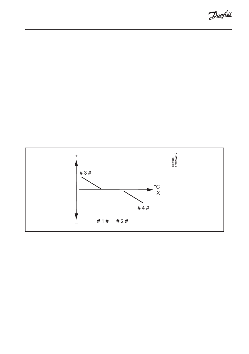
Room T limit (room temperature limitation) 3000
This section is a general description for Room temperature limitation and is only relevant if
you have installed a room temperature sensor (S2).
The ECL Comfort 110 adjusts the desired flow temperature to compensate for the difference
between the desired and the actual room temperature.
If the room temperature is higher than the desired value, the desired flow temperature can
be reduced.
The ‘Gain-max.’ (Influence, max. room temp.) determines how much the desired flow
temperature should be reduced.
Use this influence type to avoid a too high room temperature.
If the room temperature is lower than the desired value, the desired flow temperature can
be increased.
The ‘Gain-min.´ (Influence, min. room temperature) determines how much the desired flow
temperature should be increased.
Use this influence type to avoid a too low room temperature.
A typical setting will be -4.0 for ‘Gain-max.’ and 4.0 for ‘Gain-min.´
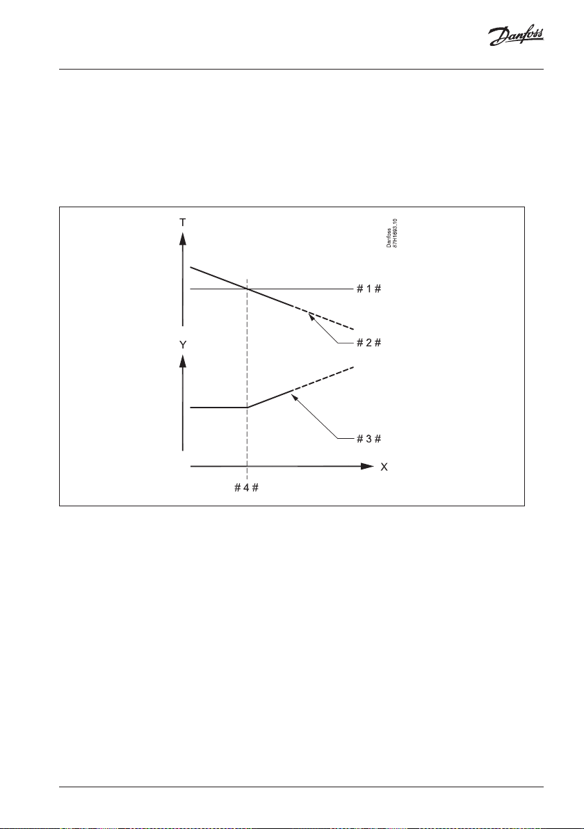
X = Room temperature
# 1 # = Desired room temperature
# 2 # = Negative influence (3182) when actual room temp. gets higher than desired
room temp.
# 3 # = Positive influence (3183) when actual room temp. gets lower than desired
room temp.
12 | © Danfoss | 2021.01 AQ197186466655en-010301

Maintenance
Comfort T (desired room temperature in Comfort mode) 3180
Setting range 5 . . . 40 °C
Setting the desired room temperature for Comfor t mode.
Saving T (desired room temperature in Saving mode) 3181
Setting range 5 . . . 40 °C
Setting the desired room temperature for Saving mode.
Gain - max. (room temp. limitation, maximum) 3182
Setting range -9.0 . . . 0.0
Determines how much the desired flow temperature will be influenced (decreased) if the ac tual room
temperature gets higher than the desired room temperature (P control).
0.0: No influence
-2.0: Minor influence
-5.0: Medium influence
-9.9: Maximum influence
Gain - min. (room temp. limitation, minimum) 3183
Setting range 0.0 . . . 9.9
Determines how much the desired flow temperature will be influenced (increased) if the actual room
temperature gets lower than the desired room temperature (P control).
9.9: Maximum influence
5.0: Medium influence
2.0: Minor influence
0.0: No influence
Intgr. time (Integration time) 3015
Setting range OFF / 1 . . . 50 s
Controls how fast the actual room temperature adapts to the desired room temperature (I control).
The “Intgr. time” function can correct the desired flow temperature with max. 8 degrees.
OFF: The control function is not influenced by the ‘Intgr. time’.
Minor value: The desired room temperature is adapted quickly.
Major value: The desired room temperature is adapted slowly.

Maintenance
Example 1
The actual room temperature is 2 degrees too low.
The ‘Gain - max.’ is set to -3.5.
The ‘Gain - min.’ is set to 2.0.
Result:
The desired flow temperature is changed by 2 x 2.0 = 4.0 degrees.
Example 2
The actual room temperature is 2 degrees too high.
The ‘Gain - max.’ is set to -3.5.
The ‘Gain - min.’ is set to 2.0.
Result:
The desired flow temperature is changed by 2 x (-3.5) = -7.0 degrees.
14 | © Danfoss | 2021.01 AQ197186466655en-010301
Maintenance
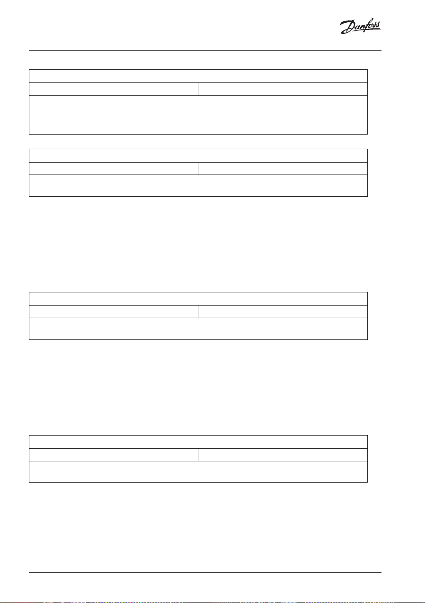
Compensation 1 and 2 4000
This section is a general description for Compensation.
Compensation is only relevant if you have installed a compensation temperature sensor (S1).
The desired flow temperature can be increased or decreased by the compensation
temperature, measured by S1. The compensation temperature is often the outdoor
temperature, but could for example be a room temperature.
This application contains 2 compensation temperature points: Compensation 1 (Comp. 1)
and Compensation 2 (Comp. 2).
An example: Compensation 1 can be set to 18 °C and Compensation 2 can be set to 24 °C.
When the compensation temperature gets lower than 18 °C, the desired flow temperature
can be increased (less demand for cooling).
When the compensation temperature gets higher than 24 °C, the desired flow temperature
can be decreased (more demand for cooling).
X = Compensation temperature
# 1 # = Compensation temperature value 1
# 2 # = Compensation temperature value 2
# 3 # = Positive influence (4063) when actual compensation temp. gets lower than
“Compensation temperature value 1”
# 4 # = Negative influence (5066) when actual compensation temp. gets higher than
“Compensation temperature value 2”
The example shows that the desired flow temperature can be influenced when the
compensation temperature gets below “Compensation temperature value 1”.
Also, the desired flow temperature can be influenced when the compensation temperature
gets above “Compensation temperature value 2”.
Maintenance
Temp. (Compensation temperature) 4060
Setting range -20 . . . 50 °C
Setting the compensation temperature value 1.
When the temperature, measured by S1, falls below or gets higher than the set compensation value,
the ECL Comfort 110 changes the desired flow temperature. The influence is set in ‘Gain - max.’ and
‘Gain - min.’.
Gain - max. (Compensation temp., limitation, maximum) 4062
Setting range -9.9 . . . 9.9
Determines how much the desired flow temperature will be influenced (increased or decreased) if the
compensation temperature gets higher than the set compensation temperature value (P control).
9.9: Maximum increase of desired flow temperature
5.0: Medium influence
2.0: Minor influence
0.0: No influence
-2.0: Minor influence
-5.0: Medium influence
-9.9: Maximum decrease of desired flow temperature
Gain - min. (Compensation temp., limitation, minimum) 4063
Setting range -9.9 . . . 9.9
Determines how much the desired flow temperature will be influenced (increased or decreased) if the
compensation temperature gets lower than the set compensation temperature value (P control).
9.9: Maximum increase of desired flow temperature
5.0: Medium influence
2.0: Minor influence
0.0: No influence
-2.0: Minor influence
-5.0: Medium influence
-9.9: Maximum decrease of desired flow temperature
Intgr. time (Integration time) 4061
Setting range OFF / 1 . . . 50 s
Controls how fast the compensation temperature changes the desired flow temperature (I control).
The “Intgr. time” function can correct the desired flow temperature with max. 8 degrees.
OFF: The control function is not influenced by the ‘Intgr. time’.
Minor value: The desired flow temperature is changed quickly.
Major value: The desired flow temperature is changed slowly.
16 | © Danfoss | 2021.01 AQ197186466655en-010301
Maintenance
Compensation 2 5000
Temp. (Compensation temperature) 5064
Setting range -20 . . . 50 °C
Setting the compensation temperature value 2.
When the temperature, measured by S1, falls below or gets higher than the set compensation value,
the ECL Comfort 110 changes the desired flow temperature. The influence is set in ‘Gain - max.’ and
‘Gain - min.’.
Gain - max. (Compensation temp., limitation, maximum) 5066
Setting range -9.9 . . . 9.9
Determines how much the desired flow temperature will be influenced (increased or decreased) if the
compensation temperature gets higher than the set compensation temperature value (P control).
9.9: Maximum increase of desired flow temperature
5.0: Medium influence
2.0: Minor influence
0.0: No influence
-2.0: Minor influence
-5.0: Medium influence
-9.9: Maximum decrease of desired flow temperature
Gain - min. (Compensation temp., limitation, minimum) 5067
Setting range -9.9 . . . 9.9
Determines how much the desired flow temperature will be influenced (increased or decreased) if the
compensation temperature gets lower than the set compensation temperature value (P control).
9.9: Maximum increase of desired flow temperature
5.0: Medium influence
2.0: Minor influence
0.0: No influence
-2.0: Minor influence
-5.0: Medium influence
-9.9: Maximum decrease of desired flow temperature
Maintenance
Intgr. time (Integration time) 5065
Setting range OFF / 1 . . . 50 s
Controls how fast the compensation temperature changes the desired flow temperature (I control).
The “Intgr. time” function can correct the desired flow temperature with max. 8 degrees.
OFF: The control function is not influenced by the ‘Intgr. time’.
Minor value: The desired flow temperature is changed quickly.
Major value: The desired flow temperature is changed slowly.
Example:
The compensation temp. value is set to 5 °C.
‘Gain. min.’ (4063) is set to 2.5.
The actual compensation temperature is 2°C (3 degrees below the limit value).
Result:
The desired flow temperature is changed by 2.5 x 3 = 7.5 degrees.
18 | © Danfoss | 2021.01 AQ197186466655en-010301

Maintenance
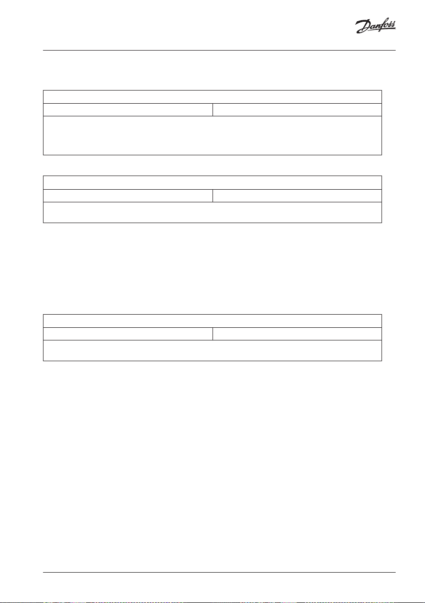
Return T limit (return temp. limitation) 6000
This section is a general description for Return temperature limitation and is only relevant if
you have installed a return temperature sensor (S4).
The ECL Comfort 110 adjusts the desired flow temperature to compensate for the difference
between the limitation temperature and the actual return temperature.
Cooling application:
If the return temperature gets lower than the limitation value, the desired flow temperature
can be increased.
The ‘Gain. -min.’ (Influence, min. return temperature) determines how much the desired flow
temperature should be increased. By this, the control valve gradually closes, resulting in a
higher return temperature.
Use this influence type to avoid a too low return temperature.
X = Return temperature
# 1 # = Limitation temperature
# 2 # = Negative influence (6035) when return temp. gets higher than limit. temp.
# 3 # = Negative influence (6036) when return temp. gets lower than limit. temp.
# 4 # = Positive influence (6036) when return temp. gets lower than limit. temp.
# 5 # = Positive influence (6035) when return temp. gets higher than limit. temp.
Maintenance
Limit (return temperature limitation value) 6030
Setting range -20 . . . 50 °C
Setting the limitation value for the return temperature.
Gain - max. (return temp. limitation, maximum) 6035
Setting range -9.0 . . . 9.9
Determines how much the desired flow temperature will be influenced (increased or decreased) if the
actual return temperature gets higher than the set return temperature limitation value (P control).
9.9: Maximum increase of desired flow temperature
5.0: Medium influence
2.0: Minor influence
0.0: No influence
-2.0: Minor influence
-5.0: Medium influence
-9.9: Maximum decrease of desired flow temperature
Gain - min. (return temp. limitation, minimum) 6036
Setting range -9.0 . . . 9.9
Determines how much the desired flow temperature will be influenced (increased or decreased) if the
actual return temperature gets lower than the set return temperature limitation value (P control).
9.9: Maximum increase of desired flow temperature
5.0: Medium influence
2.0: Minor influence
0.0: No influence
-2.0: Minor influence
-5.0: Medium influence
-9.9: Maximum decrease of desired flow temperature
Intgr. time (Integration time) 6037
Setting range OFF / 1 . . . 50 s
Controls how fast the return temperature limitation changes the desired flow temperature (I control).
The “Intgr. time” function can correct the desired flow temperature with max. 8 degrees.
OFF: The control function is not influenced by the ‘Intgr. time’.
Minor value: The desired flow temperature is changed quickly.
Major value: The desired flow temperature is changed slowly.
If the ‘Gain’ is too high and / or the ‘Intgr. time’ too low, there is a risk of unstable control.
20 | © Danfoss | 2021.01 AQ197186466655en-010301
Maintenance
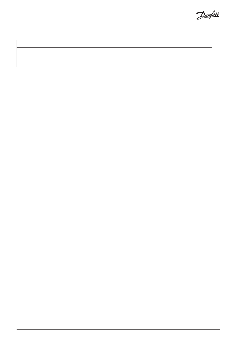
Example:
The return temperature limit is set to 12 °C.
‘Gain. min.’ (6036) is set to 2.5.
The actual return temperature is 9 °C (3 degrees below the limit value).
Result:
The desired flow temperature is changed by 2.5 x 3 = 7.5 degrees.
T = Temperature
Y = Temperature
X = Time
# 1 # = Return temperature limit
# 2 # = Return temperature
# 3 # = Desired flow temperature
# 4 # = Action point

Maintenance
Control param. (control parameters) 7000
Xp (proportional band) 7184
Setting range 1 ... 250 K
Set the proportional band. A higher value will result in a stable but slow control of the flow
temperature.
Tn (integration time constant) 7185
Setting range 5 ... 999 s
Set a high integration time constant to obtain a slow but stable reaction to deviations.
A low integration constant will make the controller react fast but with less stability.
M1 run (running time of the motorized control valve) 7186
Setting range 5 ... 250 s
‘M1 run’ is the time it takes the controlled unit to move from fully closed to fully open
position. Set the ‘M1 run’ according to the example.
How to calculate the running time of a motorized control valve
The running time of the motorized control valve is calculated using the following methods:
Seated valves
Running time = Valve stroke (mm) x actuator speed (sec. / mm)
Example: 5.0 mm x 15 sec. / mm = 75 sec.
Rotating valves
Running time = Turning degrees x actuator speed (sec. / degr.)
Example: 90 degr. x 2 sec. / degr. = 180 sec.
22 | © Danfoss | 2021.01 AQ197186466655en-010301

Maintenance
Nz (neutral zone) 7187
Setting range 1 ... 9 K
Set the acceptable flow temperature deviation.
Set the neutral zone to a high value if you can accept a high variation in flow temperature.
When the actual flow temperature is within the neutral zone, the controller does not activate
the motorized control valve.
The neutral zone is symmetrical around the desired flow temperature value, i.e. half the
value is above and half the value is below this temperature.
Min. on time (minimum activation time of valve actuator 7189
Setting range 2 . . . 50
The set value is multiplied by 20 ms (milliseconds). The time is the minimum pulse period for
activation of the valve actuator (gear motor).
The setting should be kept as high as acceptable to increase the lifetime of the valve
actuator.
Setting examples Set value x 20 ms
2 40 ms (= 0.04 sec)
10 200 ms (= 0.2 sec)
50 1000 ms (= 1 sec)

Maintenance
If you want to tune the PI regulation precisely, you can use the following
method:
• Set the ‘Tn’ (integration time constant line 6185) to its max. value (999 sec.).
• Decrease the value for the ‘Xp’ (proportional band line 6184) until the system starts
hunting with a constant amplitude (it might be necessary to force the system by setting
an extreme value).
• Find the critical time period on the temperature recording or use a stop watch.
Temp. Critical time period
Time
This time period will be characteristic for the system, and you can evaluate the settings from
this critical period.
‘Tn’ = 0.85 x critical time period
‘Xp’ = 2.2 x proportional band value in the critical time period.
If the regulation seems to be too slow, you can decrease the proportional band value by
10%.
24 | © Danfoss | 2021.01 AQ197186466655en-010301

Maintenance
Application 8000
Total stop 8021
Setting range OFF / ON
Decide whether you want a total stop during the Saving period
OFF: No total stop. The desired flow temperature is the value, set as “Saving T”
(2019). Typically a high value in order to have less or no cooling.
“Temp. max.” (2178) limitation is active.
ON: The desired flow temperature is the value, set in Standby mode.
“Temp. max.” (2178) limitation is not active.
Total stop = OFF
X = Time
Y = Desired flow temperature
# 1 # = Standby temperature
# 2 # = Saving temperature
# 3 # = Desired saving temperature
# 4 # = Comfort temperature
# 5 # = Comfort period
# 6 # = Saving period

Maintenance
Total stop = ON
X = Time
Y = Desired flow temperature
# 1 # = Standby temperature
# 2 # = Saving temperature
# 3 # = Desired saving temperature
# 4 # = Comfort temperature
# 5 # = Comfort period
# 6 # = Saving period
P1 exercise 8022
Setting range OFF / ON
Exercises the circulation pump to avoid blocking in periods without cooling demand.
OFF The pump exercise is not active.
ON: The pump is switched ON daily for 15 minutes as from 12.30.
M1 exercise 8023
Setting range OFF / ON
Exercises the control valve to avoid blocking in periods without cooling demand.
OFF The valve exercise is not active.
ON: The valve is opened daily for 15 minutes as from 12.00.
The valve is closed as from 12.15.
26 | © Danfoss | 2021.01 AQ197186466655en-010301
Maintenance
P1 start T (cooling demand) 8078
Setting range 5 . . . 40 °C
When the desired flow temperature is below the set temperature in ‘P1 start T’, the ECL Comfort 110
automatically switches ON the circulation pump.
NOTE: The control valve is fully closed as long as the circulation pump is not switched on.
P1 post-run 8040
Setting range 0 . . . 10 minutes
The circulation pump in the cooling circuit can be ON for a number of minutes (m) after cooling stop.
Cooling stop is when the desired flow temperature gets higher than the setting in ‘P1 start T’ (8078).
This P1 post-run function can utilize the remaining energy in for example a heat exchanger.
0: The circulation pump stops immediately after cooling stop.
Value: The circulation pump is ON for the set time after cooling stop.
Standby T (standby temperature) 8093
Setting range 5 . . . 40 °C
Setting the desired flow temperature for the ECL Comfor t 110 when it is in Standby mode.
The same value is set in the End user menu as desired flow temperature when in Standby mode.
Ext. (external override mode) 8141
Setting range OFF / Comfort / Saving
By means of a switch or a relay contact the ECL Comfort 110 can be overridden to ‘Comfort’ or ‘ Saving’
mode.
The override switch or relay contact is connected to the input terminals 11 and 12. When closing the
switch / relay contacts, the override is activated. The override remains active until the switch / relay
contact opens.
The override mode can be activated only when the ECL Comfort 110 is in scheduled (AUTO) mode.
OFF: Override is not possible.
Comfort: The cooling circuit is in Comfort mode when the override switch is closed.
Saving: The cooling circuit is in Saving mode when the override switch is closed.
S1 T filter (filtering of the S1 temperature) 8081
Setting range 1 . . . 200
The measured S1 temperature is filtered (dampened) by means of the set factor.
If the S1 temperature has unacceptable fluctuations a high value is recommended.
Low value: Low filtering (minor dampening)
High value: High filtering (major dampening)

Maintenance
Daylight (daylight saving time changeover) 8198
Setting range OFF / ON
Choose whether you want the change to summer / winter time to be automatic or manual.
OFF: Manually change between summer and winter time by setting the
clock backward or forward.
ON: The ECL Comfort 110’s built-in clock automatically changes + / - one hour
on the standardized days for daylight saving time changeover for Central
Europe.
ECL address (master / slave address) 8199
Setting range 0 . . . 15
This setting is relevant if more ECL Comfort 110 are connected in the same ECL Comfort system
(connected via the ECL BUS).
The ECL Comfort 110, which is physically connected with the S1 temperature sensor, must be the master
of the entire system and must have the address 15.
However, more slaves can have the address 0 if they only have to receive information about S1
temperature and system time.
NOTES:
The total cable length of max. 125 m (all temperature sensor connections and the ECL BUS) should not
be exceeded.
Cable lengths of more than 125 m may cause noise sensibilit y (EMC).
In a system with master / slave controllers, only one master controller with address 15 is allowed.
If by mistake more master controllers are present in an ECL BUS system, decide which controller is to be
mas ter.
Change the address in the remaining controllers. However, the system will operate, but not be stable
with more than one master controller.
0: The ECL Comfort 110 works as slave. The slave receives information
about the S1 temperature and system time and date.
Several slaves can have address 0.
1 . . . 9:
The ECL Comfort 110 works as slave. The slave receives information about the
S1 temperature and system time and date.
Each slave must be configured with its own address (1 ... 9).
10 . . . 14: Not used.
15: The ECL Comfort 110 is master. The master sends information about the S1
temperature and system time and date.
28 | © Danfoss | 2021.01 AQ197186466655en-010301

Maintenance
Type (application type) 8600
Setting range ??? / 131
Use this setting to restore the factory settings, if necessary.
To restore the factory settings:
Press and hold for 5 sec.
Hereafter the ECL Comfort 110 resets.
An ECL Comfort 110, new from factory, will show “???” at start-up.
Select application 131 by means of the + button.
Press and hold the “arrow-down” button for 5 sec.
Factory settings are restored. All personal settings will be deleted. It is recommended to
make a note of your personal settings in the ‘Settings overview’ for future use.

Maintenance
Service 9000
Code no. 9300
Information about the ECL Comfort 110’s code number.
Example: 087B1670
Ver. (version no.) 9301
Info ABBBCCWWYY
Information about the ECL Comfort 110’s version.
A = Hardware version
BBB = Software version
CC = Application version
WW = Production week
YY = Production year
Example: D200010516
Please state the version in connection with questions about the product, if any.
Backlight (display brightness) 9310
Setting range OFF, 1 . . . 30
The brightness of the display can be adjusted.
OFF: No backlight
1: Weak backlight
30: Strong backlight
Contrast (display contrast) 9311
Setting range 0 . . . 20
The contrast of the display can be adjusted.
0: High contrast
20: Low contrast
30 | © Danfoss | 2021.01 AQ197186466655en-010301

Maintenance
Language 9315
Setting range ENGLISH / DANSK
Choose the preferred language.
MOD address (MODBUS address) 9320
Setting range 0 . . . 250
The MODBUS related func tionality is used for production test only.
Installation
Danfoss
87B787.10
Danfoss
87B788.10
Danfoss
87B789.10
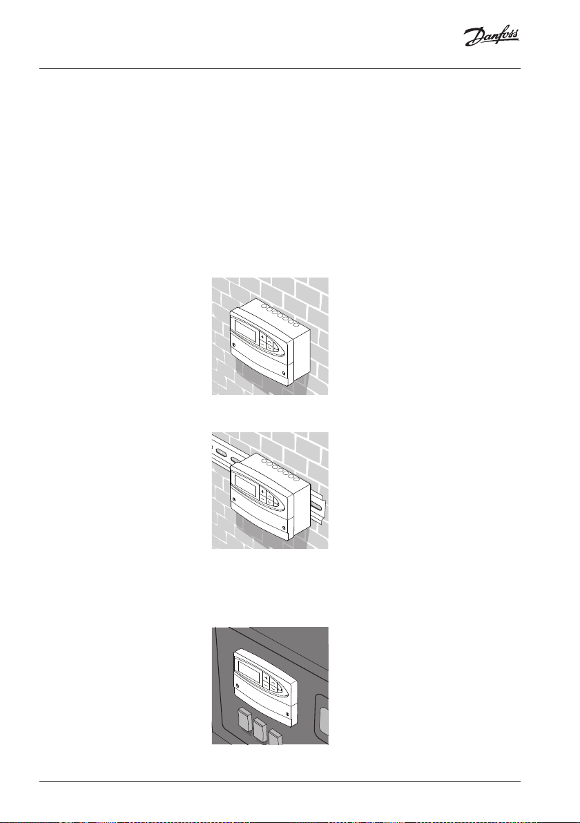
Mounting the ECL Comfort controller
For easy access, you should mount the ECL Comfort controller near the system. Select
one of the three following methods:
• Mounting on a wall
• Mounting on a DIN rail
• Mounting in a panel
Screws and rawlplugs are not supplied.
Mounting on a wall
Mount the controller on a wall with a smooth surface and establish the electrical
connections.
Mounting on a DIN rail
Mount the controller on the DIN rail and establish the electrical connections.
Mounting in a panel
Mounting kit: Order code no. 087B1249.
The panel plate thickness must not exceed 5 mm. Prepare a cut-out with the dimensions
93 x 139 mm. Insert the controller into the panel cut-out and fix it with the clamp which
is placed horisontally on the controller. Establish the electrical connections.
For further details on mounting, see the mounting guide.
32 | © Danfoss | 2021.01 AQ197186466655en-010301
Installation
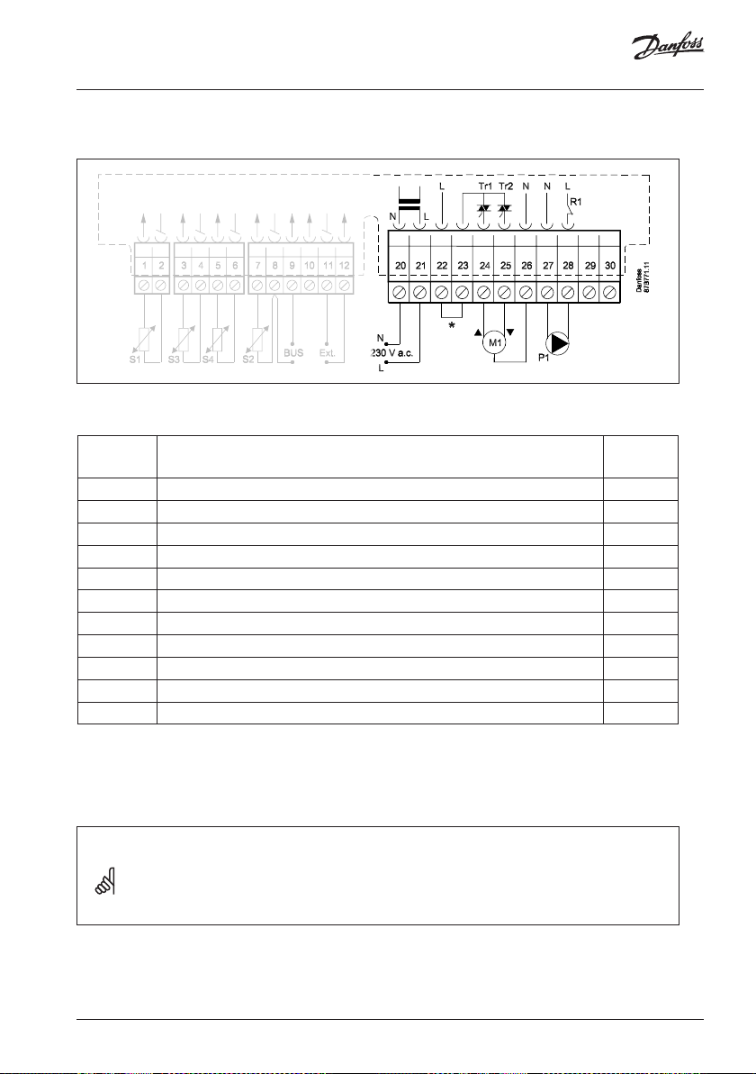
Electrical connections - 230 V a.c. - in general
* Optional connections for safety thermostat
Terminal Description Max.
load
20 Supply voltage 230 V a.c. - neutral (N)
21 Supply voltage 230 V a.c. - live (L)
22 Optional connections for safety thermostat
23 Optional connections for safety thermostat
24 M1 Actuator - open 15 VA
25 M1 Actuator - close 15 VA
26 M1 Actuator - neutral
27 P1 Circulation pump - neutral
28 P1 Circulation pump - live (relay R1) 4 (2) A *
29 Not to be used
30 Not to be used
*: Ohmic load: 4 Amp.; Inductive load: 2 Amp.
Wire cross section: 0.5 - 1.5 mm
Incorrect connection can damage the TRIAC outputs (terminals 23, 24 and 25).
2
Installation
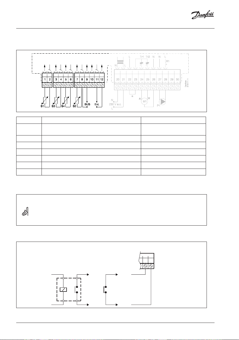
Connecting the temperature sensors and the ECL BUS
Terminal Description Type (recomm.)
1 and 2 S1 Compensation temperature sensor ESMT (Outdoor)
3 and 4 S3 Flow temperature sensor* ESMC
5 and 6 S4 Return temperature sensor ESMC
7 and 8 S2 Room temperature sensor ESM -10
8 and 9 ECL BUS
10 Not to be used
11 and 12 External override
* The sensor must always be connected in order to have the desired functionality. If the sensor is
not connected or the cable is short-circuited, the motorized control valve closes (safety function).
ESM-10 (Room)
Wire cross section for sensor connections: 0.4 - 0.75 mm
2
Total cable length: Max. 125 m (all sensors incl. the ECL BUS)
Cable lengths of more than 125 m may cause noise sensibility (EMC).
External override
ECL 110
Danfoss
11 12
# 1 # # 2 #
Override by means of a relay (# 1 #) or a switch (# 2 #).
34 | © Danfoss | 2021.01 AQ197186466655en-010301
87H1701.10
Installation
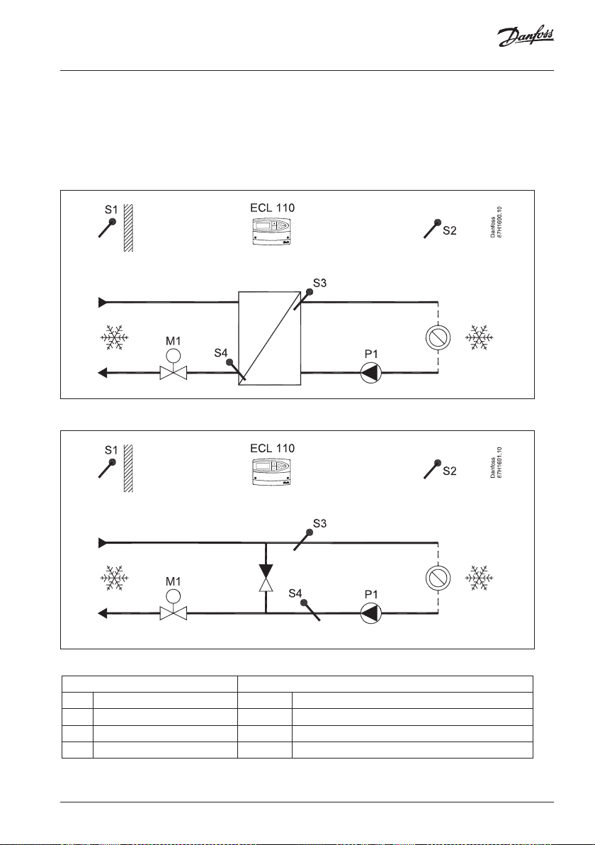
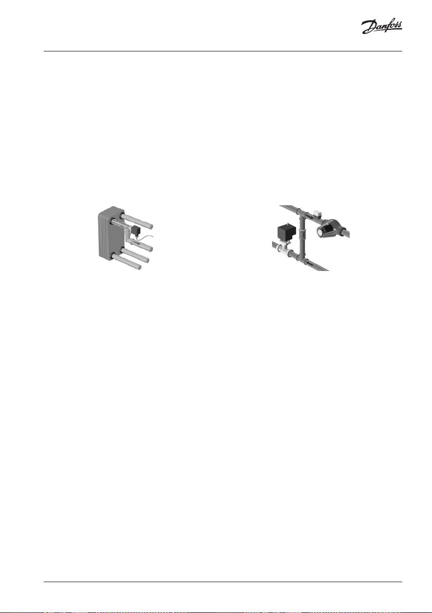
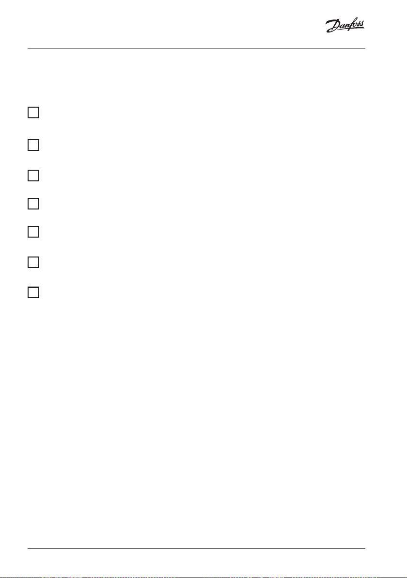
How to identify your system type
The ECL Comfort 110 is a universal controller that can be used for various systems. Based
on the shown standard systems, it is possible to configure additional systems.
Cooling system with heat exchanger
Cooling system circuit with direct connection
Sensors:
S1 Compensation temperature ECL 110 ECL Comfort 110 with cooling application 131
S2 Room temperature M1 Circulation pump
S3 Flow temperature P1 Motorized control valve
S4 Return temperature Circulation pump

Installation
dd-mm-yy hh:mm
Adapting the ECL Comfort 110 controller
When you switch on the controller the first time, it will ask you to choose language (default
language is English).
Language
English
Choose your language. Options:
English and Dansk (Danish).
Accept and go to the next menu.
When the language is chosen, the controller will ask for date and time setting.
Date - time
Set day (dd), month (mm), year (yy), hour (hh), and minuts (mm).
Change values.
Accept the chosen time and date.
When the language has been chosen, and date and time have been set, the controller can
ask for application type.
Application
Type ???
Choose application type 131.
2 sec.
Start the chosen application.
36 | © Danfoss | 2021.01 AQ197186466655en-010301
Installation
If the application 131 has already been chosen, the display shows:
Application
Type 131
Go to the ‘Maintenance’ part for further setup of your controller.

Installation
Manual control
Select control mode.
Mode COMFORT<
Wednesday
5 sec.
Go to manual mode.
Actuator M1 is opening (
Actuator M1 is closing ( )
Pump P1 is ON ( )
)
Manual mode
Valve STOP
Manual mode
Pump P1 is OFF (
Select control mode.
)
Pump ON
Mode MANUAL<
Wednesday
Manual mode should only be used for maintenance purposes. In manual mode all control
and safety functions are deactivated!
38 | © Danfoss | 2021.01 AQ197186466655en-010301
Installation
Placing the temperature sensors
It is important that the sensors are mounted in the correct position in your system.
The temperature sensor mentioned below are sensors used for the ECL Comfort series
which not all will be needed for your application!
Outdoor temperature sensor (ESMT)
The outdoor sensor should be mounted on that side of the building where it is less likely
to be exposed to direct sunshine. It should not be placed close to doors, windows or air
outlets.
Flow temperature sensor (ESMU or ESMC)
Place the sensor max. 15 cm from the mixing point. In systems with heat exchanger,
Danfoss recommends that the ESMU-type to be inserted into the exchanger flow outlet.
Make sure that the surface of the pipe is clean and even where the sensor is mounted.
Return temperature sensor (ESMU or ESMC)
The return sensor should always be placed in / on a pipe with return water flow.
Room temperature sensor (ESM-10)
Place the room sensor in the room where the temperature is to be controlled. Do not place
it on outer walls or close to windows or doors.
Checklist, electrical connections
Is the ECL Comfort controller ready for use?
Make sure that the correct power supply is connected to terminals 21 (Live)
and 20 (Neutral).
Check that the required controlled units (actuator, pump etc.) are connected
to the correct terminals.
Check that all sensors are connected to the correct terminals.
Switch on the power.
Choose manual operation as controller mode.
Check that valves open and close, and that required controlled units (pump
etc.) start and stop when operated manually.
Check that the temperatures shown in the display match the actual sensors.
40 | © Danfoss | 2021.01 AQ197186466655en-010301
Frequently asked questions in relation to cooling application
The time shown in the display is one hour off?
See the daylight saving time changeover in line 7198.
The time shown in the display is not correct?
The internal clock may have been reset, if there has been a power break for more than 36
hours. Set time and date. See line 1000.
What does the symbol mean?
The flow temperature is under influence of room temperature limitation or return
temperature limitation.
The temperature is unstable?
• Check that the flow temperature sensor is correctly connected and in the right place.
• Adjust the control parameters (line 7000).
The controller does not operate and the control valve is closed?
• Check that the flow temperature sensor is measuring the correct value, see ‘Daily use’.
• Check the influence from other measured temperatures ( ).
How to restore the factory settings?
See line 8600.
What does P and PI control mean?
P control: Proportional control.
By using a P control, the controller will change the flow temperature proportional to the
difference between a desired and an actual temperature, e.g. a room temperature.
A P control will always have an offset which not will disappear over time.
PI control: Proportional and Integrating control.
A PI control does the same as a P control, but the offset will disappear over time.
A long ‘Intgr. time’ will give a slow but stable control, and a short ‘Intgr. time’ will result in a
fast control but with a higher risk of oscillations.

Definitions in relation to cooling application
Comfort operation
Normal temperature in the cooling system controlled by the schedule. During cooling the
flow temperature in the system is lower in order to have an acceptable room temperature.
Comfort temperature
Temperature maintained in the cooling circuit during comfort periods.
Cooling circuit
The circuit for cooling the room / building.
Desired flow temperature
Temperature set in the ECL Comfort 110 and influences from the room and / or return
temperatures. This temperature is used as a reference for the control.
Desired room temperature
Temperature which is set as the desired room temperature. The temperature can only be
controlled by the ECL Comfort controller if a room temperature sensor is installed.
If a sensor is not installed, the set desired room temperature has no influence on the desired
flow temperature.
Desired temperature
Temperature based on a setting or a controller calculation.
Factory settings
Settings stored in the controller to simplify the setup of your controller the first time.
Flow temperature
Temperature measured in the flow at any time.
Limitation temperature
Temperature that influences the desired flow temperature.
42 | © Danfoss | 2021.01 AQ197186466655en-010301
Definitions in relation to cooling application
Pt 1000 sensor
All sensors used with the ECL Comfort controller are based on the Pt 1000 type. The
resistance is 1000 ohm at 0 °C and it changes with approx. 3.9 ohm / degree.
Return temperature
The temperature measured in the return can influence the desired flow temperature.
Typically, the return temperature to the cooling supply should not be too low. If so, the
desired flow temperature can be increased.
Room temperature
Temperature measured by the room temperature sensor. The room temperature can only be
controlled directly if a room temperature is measured. The room temperature can influence
the desired flow temperature.
Room temperature sensor
Temperature sensor placed in the room (reference room, typically the living room) where
the temperature is to be controlled.
Saving operation
Increased temperature in the cooling system controlled by the schedule. During less cooling
the flow temperature in the system is higher in order to save cooling energy.
Saving temperature
Temperature maintained in the cooling circuit during saving temperature periods.
Schedule
Schedule for periods with comfort and saving temperatures. The schedule can be made
individually for each week day and it consists of 2 comfort periods per day.
Time bar
The time bars illustrate scheduled periods with comfort temperature.
Disposal note
This symbol on the product indicates that it may not be disposed of as
household waste.
It must be handed over to the applicable take-back scheme for the
recycling of electrical and electronic equipment.
• Dispose of the product through channels provided for this purpose.
• Comply with all local and currently applicable laws and regulations.

!
44 | © Danfoss | DHS-SMDT/DK | 2021.01
*087R9832*
AQ197186466655en-010301
 Loading...